EP2265759B1 - Method for an energy efficient production of cellulose pulp in a continuous digester - Google Patents
Method for an energy efficient production of cellulose pulp in a continuous digester Download PDFInfo
- Publication number
- EP2265759B1 EP2265759B1 EP07835403.2A EP07835403A EP2265759B1 EP 2265759 B1 EP2265759 B1 EP 2265759B1 EP 07835403 A EP07835403 A EP 07835403A EP 2265759 B1 EP2265759 B1 EP 2265759B1
- Authority
- EP
- European Patent Office
- Prior art keywords
- impregnation
- digester
- vessel
- steam
- fluid
- Prior art date
- Legal status (The legal status is an assumption and is not a legal conclusion. Google has not performed a legal analysis and makes no representation as to the accuracy of the status listed.)
- Not-in-force
Links
Images



Classifications
-
- D—TEXTILES; PAPER
- D21—PAPER-MAKING; PRODUCTION OF CELLULOSE
- D21C—PRODUCTION OF CELLULOSE BY REMOVING NON-CELLULOSE SUBSTANCES FROM CELLULOSE-CONTAINING MATERIALS; REGENERATION OF PULPING LIQUORS; APPARATUS THEREFOR
- D21C7/00—Digesters
- D21C7/14—Means for circulating the lye
-
- D—TEXTILES; PAPER
- D21—PAPER-MAKING; PRODUCTION OF CELLULOSE
- D21C—PRODUCTION OF CELLULOSE BY REMOVING NON-CELLULOSE SUBSTANCES FROM CELLULOSE-CONTAINING MATERIALS; REGENERATION OF PULPING LIQUORS; APPARATUS THEREFOR
- D21C3/00—Pulping cellulose-containing materials
- D21C3/22—Other features of pulping processes
- D21C3/24—Continuous processes
-
- D—TEXTILES; PAPER
- D21—PAPER-MAKING; PRODUCTION OF CELLULOSE
- D21C—PRODUCTION OF CELLULOSE BY REMOVING NON-CELLULOSE SUBSTANCES FROM CELLULOSE-CONTAINING MATERIALS; REGENERATION OF PULPING LIQUORS; APPARATUS THEREFOR
- D21C7/00—Digesters
- D21C7/06—Feeding devices
-
- D—TEXTILES; PAPER
- D21—PAPER-MAKING; PRODUCTION OF CELLULOSE
- D21C—PRODUCTION OF CELLULOSE BY REMOVING NON-CELLULOSE SUBSTANCES FROM CELLULOSE-CONTAINING MATERIALS; REGENERATION OF PULPING LIQUORS; APPARATUS THEREFOR
- D21C7/00—Digesters
- D21C7/10—Heating devices
-
- D—TEXTILES; PAPER
- D21—PAPER-MAKING; PRODUCTION OF CELLULOSE
- D21C—PRODUCTION OF CELLULOSE BY REMOVING NON-CELLULOSE SUBSTANCES FROM CELLULOSE-CONTAINING MATERIALS; REGENERATION OF PULPING LIQUORS; APPARATUS THEREFOR
- D21C11/00—Regeneration of pulp liquors or effluent waste waters
- D21C11/0021—Introduction of various effluents, e.g. waste waters, into the pulping, recovery and regeneration cycle (closed-cycle)
Definitions
- the present invention concerns a method for the production of cellulose pulp in a continuous system in an energy-efficient manner, as specified by the preamble of to claim 1.
- US 7,112,256 B2 reveals a method for improving the heat economy in a continuous digestion system.
- the digestion system comprises an impregnation vessel and a digester. Chips are fed into the impregnation vessel and are there impregnated at a pre-determined impregnation temperature, before the impregnated chips are fed out from the impregnation vessel up to the top of the digester in order to be cooked. A dissolved cellulose pulp is fed out from the outlet at the bottom of the digester when the cooking process is complete. At least one black liquor withdrawal is taken from the digester, and this is added to the lower part of the impregnation vessel, in order to increase in this way the temperature of the chips before they are further fed upwards to the top of the digester vessel.
- FIG. 1 A cooking process is shown also in US 6,306,252 , Figure 2 , where the production of pure steam from water takes place.
- the black liquor in this case is withdrawn directly from the digester and it heats the water in a heat exchanger (19) before the heated water is led to flash tanks (21, 22) for the production of pure steam.
- the black liquor is led after its passage through the heat exchanger (19) to a recovery process.
- Figure 3 shows an alternative embodiment in which pure water is led to a pre-vaporiser (27). The water exchanges heat in the pre-steamer with hot black liquor (11), where the water is vaporised to pure steam.
- the pure steam can then be used in order to treat chips with steam during impregnation, while the cooled black liquor can be sent to a recovery process, can pre-treat chips in the digester, can be used as a source in order to create more pure steam, or can be flashed off in order to produce impure steam.
- EP1561856 disclose another method for improving alkali profiling and heat economy.
- the high heat value of the hot black liquor is lost in a heat exchanger heating the transport liquid return flow, and the transport liquid heated in the heat exchanger and added to the start of the transfer system could not reach the same high temperature as the hot black liquor, instead an intermediate temperature.
- the cooled black liquor, from heat exchanger in line 108 or further cooling in line 112 is added to impregnation vessel.
- a first aim of the invention is to produce pure steam in order to pre-treat the chips before the chips are to be impregnated in an impregnation vessel.
- a second aim is to exploit a withdrawal of digestion fluid from the top of the digester with the aim of obtaining the pure steam.
- a third aim is to produce the pure steam by using indirect exchange of heat between the withdrawal from the top of the digester and a pure fluid, where the pure fluid is converted to pure steam.
- a fourth aim is to obtain by indirect heat exchange a cooling of the cooking fluid withdrawn from the top of the digester, where the cooled withdrawal is subsequently used as impregnation fluid.
- a fifth aim is to exploit the heat energy in a more efficient manner than that revealed by US 7,112,256 B2 .
- a sixth aim is to obtain an impregnation process in which the impregnation fluid that is led to the impregnation vessel has a lower temperature than the process revealed by US 7,112,256 B2 .
- the invention concerns a method for the production of cellulose pulp in a continuous digester system in an energy-efficient manner.
- the method comprises an impregnation vessel in which to impregnate the chips, which chips are then fed to a subsequent digester vessel in a transfer fluid.
- a black liquor withdrawal is taken from the digester, which withdrawal is led to the bottom in order there to heat the chips before they are fed out from the impregnation vessel.
- a withdrawal of the transfer fluid is taken from the top of the digester and led to a position in order there to act as impregnation fluid in the impregnation vessel.
- the invention is characterised in that at least a portion of the transfer fluid that is withdrawn from the top of the digester passes an indirect heat exchanger, in which the transfer fluid withdrawn from the top of the digester at a temperature of at least 125 °C exchanges heat indirectly with a first fluid for the production of steam from the first fluid.
- the steam that is produced is then led to a steam pre-treatment position, upstream of the impregnation process, in order to heat the chips at the said steam pre-treatment position.
- FIG. 1 shows a first embodiment of a method for the production of cellulose pulp in a continuous digester system in an energy-efficient manner.
- the digestion system comprises an impregnation vessel 10 with an inlet at the top of the impregnation vessel 10 and an outlet at its bottom.
- Cellulose chips (CH) are continuously fed to the inlet of the impregnation vessel in order to be impregnated in an impregnation fluid in the impregnation vessel 10 at a pre-determined impregnation temperature T imp in the interval 80-120 °C.
- the impregnation temperature is at least 20 °C lower than the subsequent cooking temperature T kok .
- the impregnated chips after the completion of the impregnation are fed out from the impregnation vessel 10 through the outlet arranged at the bottom of the impregnation vessel 10.
- the impregnated chips After being fed out from the impregnation vessel 10 the impregnated chips are fed, together with a transfer fluid, in a transfer line 11 to an inlet at the top of a subsequent digester vessel 20.
- the pressurisation of the chips and the transfer fluid in the transfer line 11 is carried out with a pressurising means 13 such as, for example, a sluice feeder tap or with at least one pump.
- the chips are cooked in the digester vessel at a pre-determined cooking temperature T kok in the interval 130-160 °C.
- the cooked chips are fed out from the digester vessel after the completion of the cooking process in the digester vessel 20 as a dissolved cellulose pulp, through an outlet arranged at the bottom of the digester vessel.
- At least one black liquor withdrawal is carried out through a withdrawal strainer 23 in the digester vessel essentially at the maintained cooking temperature T kok , and this withdrawal is led along a black liquor line 22 directly to the bottom of the impregnation vessel in order there to be mixed with the chips mixture of impregnated chips and impregnation fluid.
- the aim of leading the black liquor withdrawal to the bottom of the impregnation vessel is to raise the temperature of the chips mixture at the bottom of the impregnation vessel.
- the temperature of the black liquor is at least 135 °C in association with its withdrawal from the digester.
- a portion of the transfer fluid is withdrawn from the top of the digester and led in a return line 21 to the impregnation vessel 10, where it is given time to work as impregnation fluid for at least 25% of the total impregnation time for the cellulose chips in the impregnation vessel.
- At least a portion of the transfer fluid that is withdrawn from the top of the digester passes a first indirect heat exchanger 30, in which the transfer fluid withdrawn from the top of the digester at a temperature of at least 125 °C exchanges heat indirectly with a first fluid for the production of steam from the first fluid.
- the steam that is produced is subsequently led in a line 12 directly to a steam pre-treatment position at the top of the impregnation vessel 10.
- the steam pre-heats the chips at the steam pre-treatment position, which is upstream of the impregnation in the impregnation vessel, before the impregnation starts.
- the steam pre-treatment position to which the steam is led in order to steam pre-treat the chips is held at atmospheric pressure.
- FIG 2 shows a second preferred embodiment in accordance with the method for which a patent is applied.
- This embodiment is identical with the first described embodiment in Figure 1 , with the addition that a cooling stage, in the form of a cooler 31, is arranged between the indirect heat exchanger 30 and the impregnation vessel 10.
- This cooler 31 can be constituted by a second indirect heat exchanger, where the transfer fluid withdrawn from the digester exchanges heat indirectly with a second fluid that is colder than the withdrawn transfer fluid.
- the cooler 31 may also be constituted by a flash tank that relieves the pressure of the transfer fluid that has been withdrawn from the digester and thus reduces the temperature of this transfer fluid. Steam that contains NCGs (non-condensable gases) is also flashed in association with the flashing of the fluid. The NCGs are led after withdrawal onwards to a LVHC system and/or to destruction.
- NCGs non-condensable gases
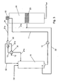
- Figure 3 shows a third preferred embodiment.
- This embodiment is identical with the second preferred embodiment shown in Figure 2 , where a second indirect heat exchanger 31 exchanges heat with a colder second fluid.
- the second fluid is led onwards in a line 12, after the heating of the second indirect heat exchanger, to the first indirect heat exchanger 30, in order there to be converted to steam after heat exchange with the transfer fluid withdrawn from the digester.
- the first fluid in the first indirect heat exchanger 30 is constituted in this third embodiment by the heated second fluid from the second indirect heat exchanger 31.
- FIG 4 shows finally a fourth preferred embodiment of the method for the production of cellulose pulp in a continuous digester system in an energy-efficient manner.
- the digestion system comprises the impregnation vessel 10 with the inlet at the top of the impregnation vessel 10 and the outlet at its bottom.
- Cellulose chips (CH) are continuously fed to the inlet of the impregnation vessel in order to be impregnated in an impregnation fluid in the impregnation vessel 10 at a pre-determined impregnation temperature T imp in the interval 80-120 °C.
- the impregnation temperature is at least 20 °C lower than the subsequent cooking temperature T kok .
- the impregnated chips after the completion of the impregnation are fed out from the impregnation vessel 10 through the outlet arranged at the bottom of the impregnation vessel 10.
- the impregnated chips After being fed out from the impregnation vessel 10, the impregnated chips are fed, together with a transfer fluid, in a transfer line 11 to the inlet at the top of the subsequent digester vessel 20.
- the pressurisation of the chips and the transfer fluid in the transfer line 11 is carried out with a pressurising means 13 such as, for example, a sluice feeder or with at least one pump.
- the chips are cooked in the digester vessel 20 at a pre-determined cooking temperature T kok in the interval 130-160 °C.
- the cooked chips are fed out after the completion of the cooking process in the digester vessel 20 as a dissolved cellulose pulp, through an outlet arranged at the bottom of the digester vessel.
- At least one black liquor withdrawal is carried out through a withdrawal strainer 23 in the digester vessel essentially at the maintained cooking temperature T kok , and this withdrawal is led along a black liquor line 22 directly to the bottom of the impregnation vessel in order there to be mixed with the chips mixture of impregnated chips and impregnation fluid.
- the aim of leading the black liquor withdrawal to the bottom of the impregnation vessel is to raise the temperature of the chips mixture at the bottom of the impregnation vessel.
- the temperature of the black liquor is at least 135 °C in association with its withdrawal from the digester.
- a steam pre-treatment vessel 40 is arranged upstream of the impregnation vessel 10. Untreated chips are fed to the steam pre-treatment vessel in order there to be pre-treated with steam. After the steam pre-treatment in the steam pre-treatment vessel 40, the treated chips fall down in a fall-pipe 42 through a rotating sluice arrangement 41 arranged between the steam pre-treatment vessel 40 and the fall-pipe 42. The steamed chips are then fed onwards in a feed line 44 to the inlet of the impregnation vessel. The feed of the chips from the outlet of the fall-pipe to the inlet of the impregnation vessel here takes place with the aid of a high-pressure tap 43.
- At least a part of the transfer fluid is withdrawn from the top of the digester and led in a return line to the fall-pipe 42, such that it is to be given time to act as impregnation fluid in the subsequent impregnation vessel.
- At least a portion of the transfer fluid that has been withdrawn from the top of the digester passes a first indirect heat exchanger 30, in which the transfer fluid withdrawn from the top of the digester at a temperature of at least 125 °C exchanges heat indirectly with a first fluid for the production of steam from the first fluid.
- the steam that is produced is then led in a line 12 to a steam pre-treatment position in the steam pre-treatment vessel 40 in order there to heat the chips before they are fed onwards to the subsequent impregnation stage.
- the steam pre-treatment position to which the steam is led in order to steam pre-treat the chips is held at atmospheric pressure.
- a portion of the transfer fluid that has been withdrawn from the top of the digester can, after passage of the first indirect heat exchanger 30, be withdrawn and led to a position in the impregnation vessel 10, where it is given time to work as impregnation fluid for at least 25% of the total impregnation time for the cellulose chips in the impregnation vessel.
- a withdrawal from the impregnation vessel can be made from a top separator at the top of the impregnation vessel and led in a line 15 to the fall-pipe 42 upstream of the impregnation vessel 10.
- the first fluid and the second fluid in all of the above embodiments are preferably constituted by water.
Landscapes
- Paper (AREA)
Description
- The present invention concerns a method for the production of cellulose pulp in a continuous system in an energy-efficient manner, as specified by the preamble of to claim 1.
-
US 7,112,256 B2 reveals a method for improving the heat economy in a continuous digestion system. The digestion system comprises an impregnation vessel and a digester. Chips are fed into the impregnation vessel and are there impregnated at a pre-determined impregnation temperature, before the impregnated chips are fed out from the impregnation vessel up to the top of the digester in order to be cooked. A dissolved cellulose pulp is fed out from the outlet at the bottom of the digester when the cooking process is complete. At least one black liquor withdrawal is taken from the digester, and this is added to the lower part of the impregnation vessel, in order to increase in this way the temperature of the chips before they are further fed upwards to the top of the digester vessel. The need to add hot steam at the top of the digester is in this way reduced. A part of the black liquor is then withdrawn from the top separator of the digester in order to be added in the impregnation vessel and there used as impregnation fluid. This invention allows the achievement of a "cold" black liquor impregnation, where the black liquor before it is taken to the impregnation vessel has to a large extent cooled by convection in the lines and through its mixing with the colder impregnation fluid and the chips. The requirement for the addition of steam at the top of the digester has at the same time been considerably reduced.Figure 2 shows an alternative embodiment in which a cooler (21) is used to reduce even further the temperature of the black liquor that has been withdrawn from the top separator. - The use of a heat exchanger, known as a "reboiler", that generates steam in cooking processes is known.
US 6,176,971 B1 reveals a cooking process in which hot black liquor, directly withdrawn from a digester vessel (and possibly having been cooled in a heat exchanger), is used to create pure steam with the aid of a reboiler (71). The pure steam (73) is then led to a steam pre-treatment vessel (17) in order there to heat the chips. The black liquor is sent after its passage through the reboiler to a recovery process. - A cooking process is shown also in
US 6,306,252 ,Figure 2 , where the production of pure steam from water takes place. The black liquor in this case is withdrawn directly from the digester and it heats the water in a heat exchanger (19) before the heated water is led to flash tanks (21, 22) for the production of pure steam. The black liquor is led after its passage through the heat exchanger (19) to a recovery process.
Figure 3 shows an alternative embodiment in which pure water is led to a pre-vaporiser (27). The water exchanges heat in the pre-steamer with hot black liquor (11), where the water is vaporised to pure steam. The pure steam can then be used in order to treat chips with steam during impregnation, while the cooled black liquor can be sent to a recovery process, can pre-treat chips in the digester, can be used as a source in order to create more pure steam, or can be flashed off in order to produce impure steam. -
EP1561856 disclose another method for improving alkali profiling and heat economy. However, the high heat value of the hot black liquor is lost in a heat exchanger heating the transport liquid return flow, and the transport liquid heated in the heat exchanger and added to the start of the transfer system could not reach the same high temperature as the hot black liquor, instead an intermediate temperature. The cooled black liquor, from heat exchanger in line 108 or further cooling in line 112 is added to impregnation vessel. - A first aim of the invention is to produce pure steam in order to pre-treat the chips before the chips are to be impregnated in an impregnation vessel.
- A second aim is to exploit a withdrawal of digestion fluid from the top of the digester with the aim of obtaining the pure steam.
- A third aim is to produce the pure steam by using indirect exchange of heat between the withdrawal from the top of the digester and a pure fluid, where the pure fluid is converted to pure steam.
- A fourth aim is to obtain by indirect heat exchange a cooling of the cooking fluid withdrawn from the top of the digester, where the cooled withdrawal is subsequently used as impregnation fluid.
- A fifth aim is to exploit the heat energy in a more efficient manner than that revealed by
US 7,112,256 B2 . - A sixth aim is to obtain an impregnation process in which the impregnation fluid that is led to the impregnation vessel has a lower temperature than the process revealed by
US 7,112,256 B2 . - The aims described above are achieved with the aid of a method as specified by the characterising part of claim 1.
- The invention concerns a method for the production of cellulose pulp in a continuous digester system in an energy-efficient manner. The method comprises an impregnation vessel in which to impregnate the chips, which chips are then fed to a subsequent digester vessel in a transfer fluid. A black liquor withdrawal is taken from the digester, which withdrawal is led to the bottom in order there to heat the chips before they are fed out from the impregnation vessel. A withdrawal of the transfer fluid is taken from the top of the digester and led to a position in order there to act as impregnation fluid in the impregnation vessel. The invention is characterised in that at least a portion of the transfer fluid that is withdrawn from the top of the digester passes an indirect heat exchanger, in which the transfer fluid withdrawn from the top of the digester at a temperature of at least 125 °C exchanges heat indirectly with a first fluid for the production of steam from the first fluid. The steam that is produced is then led to a steam pre-treatment position, upstream of the impregnation process, in order to heat the chips at the said steam pre-treatment position.
- The following positive advantages over the prior art technology are obtained with the use of the invention:
- + The impregnation fluid that is withdrawn from the digester and led to the impregnation vessel is cooled in association with the production of the steam. This is advantageous for the impregnation.
- + The conversion of pure fluid to pure steam takes place in a manner that is highly energy-efficient.
- + The heat energy that leaves the impregnation fluid is absorbed by the fluid that is converted to steam, while the impregnation fluid at the same time is cooled. This ensures that not only a cold impregnation but also a pre-heating of the chips by steam before impregnation are obtained in a very energy-efficient manner.
-
-
Figure 1 shows a first preferred embodiment of the invention. -
Figure 2 shows a second preferred embodiment of the invention. -
Figure 3 shows a third preferred embodiment of the invention. -
Figure 4 shows a fourth preferred embodiment of the invention. -
Figure 1 shows a first embodiment of a method for the production of cellulose pulp in a continuous digester system in an energy-efficient manner. The digestion system comprises animpregnation vessel 10 with an inlet at the top of theimpregnation vessel 10 and an outlet at its bottom. Cellulose chips (CH) are continuously fed to the inlet of the impregnation vessel in order to be impregnated in an impregnation fluid in theimpregnation vessel 10 at a pre-determined impregnation temperature Timp in the interval 80-120 °C. The impregnation temperature, however, is at least 20 °C lower than the subsequent cooking temperature Tkok. The impregnated chips after the completion of the impregnation are fed out from theimpregnation vessel 10 through the outlet arranged at the bottom of theimpregnation vessel 10. - After being fed out from the
impregnation vessel 10 the impregnated chips are fed, together with a transfer fluid, in atransfer line 11 to an inlet at the top of asubsequent digester vessel 20. The pressurisation of the chips and the transfer fluid in thetransfer line 11 is carried out with a pressurising means 13 such as, for example, a sluice feeder tap or with at least one pump. The chips are cooked in the digester vessel at a pre-determined cooking temperature Tkok in the interval 130-160 °C. The cooked chips are fed out from the digester vessel after the completion of the cooking process in thedigester vessel 20 as a dissolved cellulose pulp, through an outlet arranged at the bottom of the digester vessel. - At least one black liquor withdrawal is carried out through a
withdrawal strainer 23 in the digester vessel essentially at the maintained cooking temperature Tkok, and this withdrawal is led along ablack liquor line 22 directly to the bottom of the impregnation vessel in order there to be mixed with the chips mixture of impregnated chips and impregnation fluid. The aim of leading the black liquor withdrawal to the bottom of the impregnation vessel is to raise the temperature of the chips mixture at the bottom of the impregnation vessel. The temperature of the black liquor is at least 135 °C in association with its withdrawal from the digester. - A portion of the transfer fluid is withdrawn from the top of the digester and led in a
return line 21 to theimpregnation vessel 10, where it is given time to work as impregnation fluid for at least 25% of the total impregnation time for the cellulose chips in the impregnation vessel. At least a portion of the transfer fluid that is withdrawn from the top of the digester passes a firstindirect heat exchanger 30, in which the transfer fluid withdrawn from the top of the digester at a temperature of at least 125 °C exchanges heat indirectly with a first fluid for the production of steam from the first fluid. - The steam that is produced is subsequently led in a
line 12 directly to a steam pre-treatment position at the top of theimpregnation vessel 10. The steam pre-heats the chips at the steam pre-treatment position, which is upstream of the impregnation in the impregnation vessel, before the impregnation starts. The steam pre-treatment position to which the steam is led in order to steam pre-treat the chips is held at atmospheric pressure. - It is also possible for a subtraction of the transfer fluid withdrawn from the digester to be withdrawn from the
return line 21, where the subfraction is led in areturn line 21 b such that it can be mixed with the black liquor withdrawal in theblack liquor line 22. -
Figure 2 shows a second preferred embodiment in accordance with the method for which a patent is applied. This embodiment is identical with the first described embodiment inFigure 1 , with the addition that a cooling stage, in the form of a cooler 31, is arranged between theindirect heat exchanger 30 and theimpregnation vessel 10. - This cooler 31 can be constituted by a second indirect heat exchanger, where the transfer fluid withdrawn from the digester exchanges heat indirectly with a second fluid that is colder than the withdrawn transfer fluid.
- The cooler 31 may also be constituted by a flash tank that relieves the pressure of the transfer fluid that has been withdrawn from the digester and thus reduces the temperature of this transfer fluid. Steam that contains NCGs (non-condensable gases) is also flashed in association with the flashing of the fluid. The NCGs are led after withdrawal onwards to a LVHC system and/or to destruction.
-
Figure 3 shows a third preferred embodiment. This embodiment is identical with the second preferred embodiment shown inFigure 2 , where a secondindirect heat exchanger 31 exchanges heat with a colder second fluid. However, in this third embodiment, the second fluid is led onwards in aline 12, after the heating of the second indirect heat exchanger, to the firstindirect heat exchanger 30, in order there to be converted to steam after heat exchange with the transfer fluid withdrawn from the digester. Thus, the first fluid in the firstindirect heat exchanger 30 is constituted in this third embodiment by the heated second fluid from the secondindirect heat exchanger 31. -
Figure 4 shows finally a fourth preferred embodiment of the method for the production of cellulose pulp in a continuous digester system in an energy-efficient manner. The digestion system comprises theimpregnation vessel 10 with the inlet at the top of theimpregnation vessel 10 and the outlet at its bottom. Cellulose chips (CH) are continuously fed to the inlet of the impregnation vessel in order to be impregnated in an impregnation fluid in theimpregnation vessel 10 at a pre-determined impregnation temperature Timp in the interval 80-120 °C. The impregnation temperature, however, is at least 20 °C lower than the subsequent cooking temperature Tkok. The impregnated chips after the completion of the impregnation are fed out from theimpregnation vessel 10 through the outlet arranged at the bottom of theimpregnation vessel 10. - After being fed out from the
impregnation vessel 10, the impregnated chips are fed, together with a transfer fluid, in atransfer line 11 to the inlet at the top of thesubsequent digester vessel 20. The pressurisation of the chips and the transfer fluid in thetransfer line 11 is carried out with a pressurising means 13 such as, for example, a sluice feeder or with at least one pump. The chips are cooked in thedigester vessel 20 at a pre-determined cooking temperature Tkok in the interval 130-160 °C. The cooked chips are fed out after the completion of the cooking process in thedigester vessel 20 as a dissolved cellulose pulp, through an outlet arranged at the bottom of the digester vessel. - At least one black liquor withdrawal is carried out through a
withdrawal strainer 23 in the digester vessel essentially at the maintained cooking temperature Tkok, and this withdrawal is led along ablack liquor line 22 directly to the bottom of the impregnation vessel in order there to be mixed with the chips mixture of impregnated chips and impregnation fluid. The aim of leading the black liquor withdrawal to the bottom of the impregnation vessel is to raise the temperature of the chips mixture at the bottom of the impregnation vessel. The temperature of the black liquor is at least 135 °C in association with its withdrawal from the digester. - A steam
pre-treatment vessel 40 is arranged upstream of theimpregnation vessel 10. Untreated chips are fed to the steam pre-treatment vessel in order there to be pre-treated with steam. After the steam pre-treatment in the steampre-treatment vessel 40, the treated chips fall down in a fall-pipe 42 through arotating sluice arrangement 41 arranged between the steampre-treatment vessel 40 and the fall-pipe 42. The steamed chips are then fed onwards in afeed line 44 to the inlet of the impregnation vessel. The feed of the chips from the outlet of the fall-pipe to the inlet of the impregnation vessel here takes place with the aid of a high-pressure tap 43. - At least a part of the transfer fluid is withdrawn from the top of the digester and led in a return line to the fall-
pipe 42, such that it is to be given time to act as impregnation fluid in the subsequent impregnation vessel. At least a portion of the transfer fluid that has been withdrawn from the top of the digester passes a firstindirect heat exchanger 30, in which the transfer fluid withdrawn from the top of the digester at a temperature of at least 125 °C exchanges heat indirectly with a first fluid for the production of steam from the first fluid. - The steam that is produced is then led in a
line 12 to a steam pre-treatment position in the steampre-treatment vessel 40 in order there to heat the chips before they are fed onwards to the subsequent impregnation stage. The steam pre-treatment position to which the steam is led in order to steam pre-treat the chips is held at atmospheric pressure. - It is also possible that a portion of the transfer fluid that has been withdrawn from the top of the digester can, after passage of the first
indirect heat exchanger 30, be withdrawn and led to a position in theimpregnation vessel 10, where it is given time to work as impregnation fluid for at least 25% of the total impregnation time for the cellulose chips in the impregnation vessel. - Furthermore, a withdrawal from the impregnation vessel can be made from a top separator at the top of the impregnation vessel and led in a
line 15 to the fall-pipe 42 upstream of theimpregnation vessel 10. - It is also possible for a subfraction of the transfer fluid withdrawn from the digester to be withdrawn from the
return line 21, where the subfraction is led in areturn line 21b such that it can be mixed with the black liquor withdrawal in theblack liquor line 22. - The first fluid and the second fluid in all of the above embodiments are preferably constituted by water.
- The following advantages, among others, are achieved with the invention:
- + The transfer fluid that is withdrawn from the digester and led to the impregnation vessel is cooled in association with the production of the steam. This is advantageous for the impregnation.
- + The conversion of pure fluid to pure steam takes place in a manner that is highly energy-efficient.
- + The heat energy that leaves the impregnation fluid is absorbed by the fluid that is converted to steam, while the impregnation fluid is at the same time cooled. This ensures that not only a cold impregnation but also a pre-heating of the chips by steam before impregnation are obtained in a very energy-efficient manner.
- Several variants in addition to the embodiments described above are possible within the scope of the attached patent claims.
Claims (15)
- A method for the production of cellulose pulp in a continuous digestion system in an energy-efficient manner, where the method comprises the following steps:a) cellulose chips (CH) are continuously fed to an inlet of an impregnation vessel (10) in order to be impregnated in an impregnation fluid in the impregnation vessel at a pre-determined impregnation temperature (Timp);b) when the impregnation is complete, the impregnated chips are fed in a transfer fluid to an inlet at the top of a digester vessel (20), in order to be cooked in the digester vessel at a pre-determined cooking temperature (Tkok), after which the dissolved pulp is fed out from the digester vessel through an outlet arranged at the bottom of the digester vessel;c) at least one black liquor withdrawal essentially at the cooking temperature (Tkok) is carried out at the digester vessel, and this is led to the bottom of the impregnation vessel in order there to be mixed with the chips mixture of impregnated chips and impregnation fluid, where the purpose of the black liquor withdrawal is to increase the temperature of the chips mixture at the bottom of the impregnation vessel, the temperature of the black liquor being at least 135 °C in association with the withdrawal from the digester;d) a portion of the transfer fluid is withdrawn from the top of the digester and led to a position where it is given time to work as impregnation fluid for at least 25% of the total impregnation time for the cellulose chips in the impregnation vessel, characterised in thate) at least a portion of the transfer fluid that is withdrawn from the top of the digester passes a first indirect heat exchanger (30), in which the transfer fluid withdrawn from the top of the digester at a temperature of at least 125 °C exchanges heat indirectly with a first fluid for the production of steam from the first fluid and for cooling of the transfer fluid;f) the steam that is produced is then led to a steam pre-treatment position, upstream of the impregnation process, in order to heat the chips at the steam pre-treatment position, and in thatg) the cooled transfer fluid is used as impregnation fluid at step d.
- The method according to claim 1, characterised in that the steam is used for steam pre-treatment at atmospheric pressure.
- The method according to either claim 1 or 2, characterised in that the steam is led to the impregnation vessel.
- The method according to claim 3, characterised in that the transfer fluid withdrawn from the digester is led, after passage of the first indirect heat exchanger (30), to the impregnation vessel.
- The method according to claim 4, characterised in that the transfer fluid withdrawn from the digester, after passage of the first indirect heat exchanger, also passes a cooling step before it is led to the impregnation vessel.
- The method according to claim 5, characterised in that the cooling step is constituted by a second indirect heat exchanger (31), where the withdrawn transfer fluid exchanges heat indirectly with a second fluid.
- The method according to claim 6, characterised in that the second fluid that is heated in the second indirect heat exchanger is led, after being heated, to the first indirect heat exchanger in order there to be converted to steam.
- The method according to claim 5, characterised in that the cooling step is constituted by a flash tank (31) that reduces the pressure of the transfer fluid withdrawn from the digester, and thus reduces the temperature of the same.
- The method according to claims 1-2, characterised in that the steam is led to a steam pre-treatment vessel arranged upstream of the impregnation vessel, in which steam pre-treatment vessel the chips are pre-treated with steam before being fed onwards to the impregnation vessel.
- The method according to claim 9, characterised in that at least a part of the transfer fluid withdrawn from the digester is led, after passage of the first indirect heat exchanger (30), to the impregnation vessel.
- The method according to either claim 9 or 10, characterised in that at least a part of the transfer fluid withdrawn from the digester is led, after passage of the first indirect heat exchanger (30), to a fall-pipe, which fall-pipe is arranged after the steam pre-treatment vessel and before the impregnation vessel, when seen in the direction of motion of the chips.
- The method according to any one of claims 9-11, characterised in that fluid is withdrawn from a top separator at the top of the impregnation vessel and led to the fall-pipe.
- The method according to any one of the preceding claims, characterised in that the fluid in the first indirect heat exchanger is constituted by water and that the steam that is produced consists of pure water steam.
- The method according to either claim 5 or 6, characterised in that the fluid in the second indirect heat exchanger is constituted by water.
- The method according to any one of the preceding claims, characterised in that a subfraction of the transfer fluid withdrawn from the digester is led directly after the withdrawal to be mixed with the black liquor withdrawal, further down in the digester.
Applications Claiming Priority (2)
| Application Number | Priority Date | Filing Date | Title |
|---|---|---|---|
| SE0602349A SE0602349L (en) | 2006-11-07 | 2006-11-07 | Process for energy-efficient production of cellulose pulp in a continuous cookery |
| PCT/SE2007/050819 WO2008057040A1 (en) | 2006-11-07 | 2007-11-05 | Method for an energy efficient production of cellulose pulp in a continuous digester |
Publications (3)
| Publication Number | Publication Date |
|---|---|
| EP2265759A1 EP2265759A1 (en) | 2010-12-29 |
| EP2265759A4 EP2265759A4 (en) | 2013-01-09 |
| EP2265759B1 true EP2265759B1 (en) | 2014-05-21 |
Family
ID=39327455
Family Applications (1)
| Application Number | Title | Priority Date | Filing Date |
|---|---|---|---|
| EP07835403.2A Not-in-force EP2265759B1 (en) | 2006-11-07 | 2007-11-05 | Method for an energy efficient production of cellulose pulp in a continuous digester |
Country Status (7)
| Country | Link |
|---|---|
| US (1) | US8691049B2 (en) |
| EP (1) | EP2265759B1 (en) |
| JP (1) | JP5130302B2 (en) |
| CN (1) | CN101535562B (en) |
| BR (1) | BRPI0718575A8 (en) |
| SE (1) | SE0602349L (en) |
| WO (1) | WO2008057040A1 (en) |
Families Citing this family (5)
| Publication number | Priority date | Publication date | Assignee | Title |
|---|---|---|---|---|
| US8444809B2 (en) * | 2007-06-25 | 2013-05-21 | Andritz Inc. | Method and system for direct contact of hot liquor with wood chips in transfer circulation |
| US9644317B2 (en) * | 2014-11-26 | 2017-05-09 | International Paper Company | Continuous digester and feeding system |
| SE539449C2 (en) * | 2015-11-16 | 2017-09-26 | Valmet Oy | Method for heating cellulosic material to full cooking temperature in digesters |
| FI127712B (en) * | 2016-04-22 | 2018-12-31 | Andritz Oy | METHOD AND ARRANGEMENT FOR PROCESS STEAM PRODUCTION |
| FI131367B1 (en) * | 2016-06-06 | 2025-03-11 | Andritz Oy | Process of producing chemical pulp in digester |
Family Cites Families (12)
| Publication number | Priority date | Publication date | Assignee | Title |
|---|---|---|---|---|
| CN87103255B (en) * | 1987-04-29 | 1988-10-05 | 轻工业部杭州轻工机械设计研究所 | Feeding device of continuous digester |
| FI82079C (en) * | 1989-04-27 | 1993-05-11 | Poeyry Jaakko & Co Oy | Foerfarande och anordning Foer kontinuerlig kokning av Cellulosa |
| SE502134C2 (en) | 1994-02-10 | 1995-08-28 | Kvaerner Pulping Tech | Optimization of liquid / wood ratio in pre-impregnation vessels and continuous boiler in preparation of chemical pulp |
| US6306252B1 (en) | 1995-04-10 | 2001-10-23 | Andritz-Ahlstrom Inc. | Heat recovery from spent digester cooking liquor |
| US5635026A (en) * | 1995-11-13 | 1997-06-03 | Ahlstrom Machinery Inc. | Cooking cellulose material with high alkali concentrations and/or high pH |
| US5958181A (en) | 1997-08-07 | 1999-09-28 | Ahlstrom Machinery, Inc. | Continuous cooking with a two-stage cool impregnation |
| US6203662B1 (en) * | 1997-08-07 | 2001-03-20 | Kvaerner Pulping Ab | Method for the continuous cooking of pulp in a digester system having a top separator |
| US6176971B1 (en) | 1998-11-18 | 2001-01-23 | Andritz-Ahlstrom Inc. | Heat economy enhancements for the recovery and use of energy obtained from spent cooking liquors |
| SE520956C2 (en) * | 2001-12-05 | 2003-09-16 | Kvaerner Pulping Tech | Continuous boiling with extra residence time for drained liquid outside the boiler |
| SE0200185L (en) * | 2002-01-24 | 2002-12-10 | Kvaerner Pulping Tech | Process for increasing the heating economy of the boiler system during continuous boiling |
| SE527058C2 (en) * | 2004-02-09 | 2005-12-13 | Kvaerner Pulping Tech | Continuous cooking process with improved heat economy |
| FI120547B (en) * | 2004-10-04 | 2009-11-30 | Metso Paper Inc | Alkaline cooking process and pulp making plant |
-
2006
- 2006-11-07 SE SE0602349A patent/SE0602349L/en not_active IP Right Cessation
-
2007
- 2007-11-05 JP JP2009536201A patent/JP5130302B2/en not_active Expired - Fee Related
- 2007-11-05 US US12/443,925 patent/US8691049B2/en not_active Expired - Fee Related
- 2007-11-05 EP EP07835403.2A patent/EP2265759B1/en not_active Not-in-force
- 2007-11-05 CN CN200780041440.XA patent/CN101535562B/en not_active Expired - Fee Related
- 2007-11-05 WO PCT/SE2007/050819 patent/WO2008057040A1/en not_active Ceased
- 2007-11-05 BR BRPI0718575A patent/BRPI0718575A8/en not_active IP Right Cessation
Also Published As
| Publication number | Publication date |
|---|---|
| JP5130302B2 (en) | 2013-01-30 |
| EP2265759A1 (en) | 2010-12-29 |
| US8691049B2 (en) | 2014-04-08 |
| SE530332C2 (en) | 2008-05-06 |
| EP2265759A4 (en) | 2013-01-09 |
| WO2008057040A1 (en) | 2008-05-15 |
| SE0602349L (en) | 2008-05-06 |
| CN101535562A (en) | 2009-09-16 |
| US20100071861A1 (en) | 2010-03-25 |
| BRPI0718575A8 (en) | 2015-12-01 |
| BRPI0718575A2 (en) | 2014-12-23 |
| JP2010509515A (en) | 2010-03-25 |
| CN101535562B (en) | 2012-09-26 |
Similar Documents
| Publication | Publication Date | Title |
|---|---|---|
| US8808498B2 (en) | Heat recovery from spent cooking liquor in a digester plant of a chemical pulp mill | |
| US9194080B2 (en) | Two vessel reactor system and method for hydrolysis and digestion of wood chips with chemical enhanced wash method | |
| FI82079C (en) | Foerfarande och anordning Foer kontinuerlig kokning av Cellulosa | |
| US8512514B2 (en) | Method and system to generate steam in a digester plant of a chemical pulp mill | |
| US8691049B2 (en) | Method for an energy efficient production of cellulose pulp in a continuous digester | |
| EP3114274B1 (en) | Method and arrangement for generating steam at a digesterplant of a chemical pulp mill | |
| US7112256B2 (en) | Method for continuous cooking of chemical pulp to improve heat economy | |
| US7547374B2 (en) | Method for impregnating chips in a continuous digestion system | |
| US7901541B2 (en) | Method and arrangement for impregnating chips | |
| EP3464715B1 (en) | Method of producing chemical pulp at a digester plant of a chemical pulp mill | |
| EP1561856B1 (en) | Method for continuous cooking of cellulose pulp | |
| EP1932967B1 (en) | A method for producing cellulose pulp in a continuous digester in an energy-efficient manner | |
| CN101535565A (en) | A method and equipment for the evaporation of black liquor that is obtained from a digestion process during the production of cellulose pulp | |
| WO2007073333A1 (en) | System and method for the generation of steam from hot black liquor in a digester plant | |
| SE534130C2 (en) | Method and apparatus for heating a chip slurry in the transfer line between impregnation vessels and boilers in the production of pulp | |
| EP3377696A1 (en) | Method for heating cellulosic material to full cooking temperature in digesters | |
| FI126251B (en) | Method and device for heating wood chips slurry |
Legal Events
| Date | Code | Title | Description |
|---|---|---|---|
| PUAI | Public reference made under article 153(3) epc to a published international application that has entered the european phase |
Free format text: ORIGINAL CODE: 0009012 |
|
| PUAI | Public reference made under article 153(3) epc to a published international application that has entered the european phase |
Free format text: ORIGINAL CODE: 0009012 |
|
| 17P | Request for examination filed |
Effective date: 20090608 |
|
| AK | Designated contracting states |
Kind code of ref document: A1 Designated state(s): AT BE BG CH CY CZ DE DK EE ES FI FR GB GR HU IE IS IT LI LT LU LV MC MT NL PL PT RO SE SI SK TR |
|
| RAP1 | Party data changed (applicant data changed or rights of an application transferred) |
Owner name: METSO PAPER SWEDEN AB |
|
| A4 | Supplementary search report drawn up and despatched |
Effective date: 20121207 |
|
| RIC1 | Information provided on ipc code assigned before grant |
Ipc: D21C 3/24 20060101AFI20121203BHEP |
|
| GRAP | Despatch of communication of intention to grant a patent |
Free format text: ORIGINAL CODE: EPIDOSNIGR1 |
|
| INTG | Intention to grant announced |
Effective date: 20131217 |
|
| GRAS | Grant fee paid |
Free format text: ORIGINAL CODE: EPIDOSNIGR3 |
|
| GRAA | (expected) grant |
Free format text: ORIGINAL CODE: 0009210 |
|
| AK | Designated contracting states |
Kind code of ref document: B1 Designated state(s): AT BE BG CH CY CZ DE DK EE ES FI FR GB GR HU IE IS IT LI LT LU LV MC MT NL PL PT RO SE SI SK TR |
|
| REG | Reference to a national code |
Ref country code: GB Ref legal event code: FG4D |
|
| REG | Reference to a national code |
Ref country code: CH Ref legal event code: EP |
|
| REG | Reference to a national code |
Ref country code: AT Ref legal event code: REF Ref document number: 669682 Country of ref document: AT Kind code of ref document: T Effective date: 20140615 |
|
| RAP2 | Party data changed (patent owner data changed or rights of a patent transferred) |
Owner name: VALMET AKTIEBOLAG |
|
| REG | Reference to a national code |
Ref country code: IE Ref legal event code: FG4D |
|
| REG | Reference to a national code |
Ref country code: DE Ref legal event code: R096 Ref document number: 602007036890 Country of ref document: DE Effective date: 20140703 |
|
| REG | Reference to a national code |
Ref country code: NL Ref legal event code: VDEP Effective date: 20140521 Ref country code: AT Ref legal event code: MK05 Ref document number: 669682 Country of ref document: AT Kind code of ref document: T Effective date: 20140521 |
|
| REG | Reference to a national code |
Ref country code: LT Ref legal event code: MG4D |
|
| PG25 | Lapsed in a contracting state [announced via postgrant information from national office to epo] |
Ref country code: LT Free format text: LAPSE BECAUSE OF FAILURE TO SUBMIT A TRANSLATION OF THE DESCRIPTION OR TO PAY THE FEE WITHIN THE PRESCRIBED TIME-LIMIT Effective date: 20140521 Ref country code: GR Free format text: LAPSE BECAUSE OF FAILURE TO SUBMIT A TRANSLATION OF THE DESCRIPTION OR TO PAY THE FEE WITHIN THE PRESCRIBED TIME-LIMIT Effective date: 20140822 Ref country code: IS Free format text: LAPSE BECAUSE OF FAILURE TO SUBMIT A TRANSLATION OF THE DESCRIPTION OR TO PAY THE FEE WITHIN THE PRESCRIBED TIME-LIMIT Effective date: 20140921 |
|
| PG25 | Lapsed in a contracting state [announced via postgrant information from national office to epo] |
Ref country code: ES Free format text: LAPSE BECAUSE OF FAILURE TO SUBMIT A TRANSLATION OF THE DESCRIPTION OR TO PAY THE FEE WITHIN THE PRESCRIBED TIME-LIMIT Effective date: 20140521 Ref country code: PL Free format text: LAPSE BECAUSE OF FAILURE TO SUBMIT A TRANSLATION OF THE DESCRIPTION OR TO PAY THE FEE WITHIN THE PRESCRIBED TIME-LIMIT Effective date: 20140521 Ref country code: AT Free format text: LAPSE BECAUSE OF FAILURE TO SUBMIT A TRANSLATION OF THE DESCRIPTION OR TO PAY THE FEE WITHIN THE PRESCRIBED TIME-LIMIT Effective date: 20140521 Ref country code: LV Free format text: LAPSE BECAUSE OF FAILURE TO SUBMIT A TRANSLATION OF THE DESCRIPTION OR TO PAY THE FEE WITHIN THE PRESCRIBED TIME-LIMIT Effective date: 20140521 Ref country code: SE Free format text: LAPSE BECAUSE OF FAILURE TO SUBMIT A TRANSLATION OF THE DESCRIPTION OR TO PAY THE FEE WITHIN THE PRESCRIBED TIME-LIMIT Effective date: 20140521 |
|
| PG25 | Lapsed in a contracting state [announced via postgrant information from national office to epo] |
Ref country code: PT Free format text: LAPSE BECAUSE OF FAILURE TO SUBMIT A TRANSLATION OF THE DESCRIPTION OR TO PAY THE FEE WITHIN THE PRESCRIBED TIME-LIMIT Effective date: 20140922 |
|
| PG25 | Lapsed in a contracting state [announced via postgrant information from national office to epo] |
Ref country code: RO Free format text: LAPSE BECAUSE OF FAILURE TO SUBMIT A TRANSLATION OF THE DESCRIPTION OR TO PAY THE FEE WITHIN THE PRESCRIBED TIME-LIMIT Effective date: 20140521 Ref country code: BE Free format text: LAPSE BECAUSE OF FAILURE TO SUBMIT A TRANSLATION OF THE DESCRIPTION OR TO PAY THE FEE WITHIN THE PRESCRIBED TIME-LIMIT Effective date: 20140521 Ref country code: CZ Free format text: LAPSE BECAUSE OF FAILURE TO SUBMIT A TRANSLATION OF THE DESCRIPTION OR TO PAY THE FEE WITHIN THE PRESCRIBED TIME-LIMIT Effective date: 20140521 Ref country code: EE Free format text: LAPSE BECAUSE OF FAILURE TO SUBMIT A TRANSLATION OF THE DESCRIPTION OR TO PAY THE FEE WITHIN THE PRESCRIBED TIME-LIMIT Effective date: 20140521 Ref country code: DK Free format text: LAPSE BECAUSE OF FAILURE TO SUBMIT A TRANSLATION OF THE DESCRIPTION OR TO PAY THE FEE WITHIN THE PRESCRIBED TIME-LIMIT Effective date: 20140521 Ref country code: SK Free format text: LAPSE BECAUSE OF FAILURE TO SUBMIT A TRANSLATION OF THE DESCRIPTION OR TO PAY THE FEE WITHIN THE PRESCRIBED TIME-LIMIT Effective date: 20140521 |
|
| REG | Reference to a national code |
Ref country code: DE Ref legal event code: R026 Ref document number: 602007036890 Country of ref document: DE |
|
| PG25 | Lapsed in a contracting state [announced via postgrant information from national office to epo] |
Ref country code: NL Free format text: LAPSE BECAUSE OF FAILURE TO SUBMIT A TRANSLATION OF THE DESCRIPTION OR TO PAY THE FEE WITHIN THE PRESCRIBED TIME-LIMIT Effective date: 20140521 |
|
| PLBI | Opposition filed |
Free format text: ORIGINAL CODE: 0009260 |
|
| PLAX | Notice of opposition and request to file observation + time limit sent |
Free format text: ORIGINAL CODE: EPIDOSNOBS2 |
|
| 26 | Opposition filed |
Opponent name: ANDRITZ OY Effective date: 20150220 |
|
| PLAB | Opposition data, opponent's data or that of the opponent's representative modified |
Free format text: ORIGINAL CODE: 0009299OPPO |
|
| PG25 | Lapsed in a contracting state [announced via postgrant information from national office to epo] |
Ref country code: IT Free format text: LAPSE BECAUSE OF FAILURE TO SUBMIT A TRANSLATION OF THE DESCRIPTION OR TO PAY THE FEE WITHIN THE PRESCRIBED TIME-LIMIT Effective date: 20140521 |
|
| REG | Reference to a national code |
Ref country code: DE Ref legal event code: R026 Ref document number: 602007036890 Country of ref document: DE Effective date: 20150220 |
|
| R26 | Opposition filed (corrected) |
Opponent name: ANDRITZ OY Effective date: 20150220 |
|
| REG | Reference to a national code |
Ref country code: DE Ref legal event code: R119 Ref document number: 602007036890 Country of ref document: DE |
|
| PLBB | Reply of patent proprietor to notice(s) of opposition received |
Free format text: ORIGINAL CODE: EPIDOSNOBS3 |
|
| PG25 | Lapsed in a contracting state [announced via postgrant information from national office to epo] |
Ref country code: LU Free format text: LAPSE BECAUSE OF FAILURE TO SUBMIT A TRANSLATION OF THE DESCRIPTION OR TO PAY THE FEE WITHIN THE PRESCRIBED TIME-LIMIT Effective date: 20141105 Ref country code: MC Free format text: LAPSE BECAUSE OF FAILURE TO SUBMIT A TRANSLATION OF THE DESCRIPTION OR TO PAY THE FEE WITHIN THE PRESCRIBED TIME-LIMIT Effective date: 20140521 |
|
| REG | Reference to a national code |
Ref country code: CH Ref legal event code: PL |
|
| PLAB | Opposition data, opponent's data or that of the opponent's representative modified |
Free format text: ORIGINAL CODE: 0009299OPPO |
|
| GBPC | Gb: european patent ceased through non-payment of renewal fee |
Effective date: 20141105 |
|
| PG25 | Lapsed in a contracting state [announced via postgrant information from national office to epo] |
Ref country code: LI Free format text: LAPSE BECAUSE OF NON-PAYMENT OF DUE FEES Effective date: 20141130 Ref country code: SI Free format text: LAPSE BECAUSE OF FAILURE TO SUBMIT A TRANSLATION OF THE DESCRIPTION OR TO PAY THE FEE WITHIN THE PRESCRIBED TIME-LIMIT Effective date: 20140521 Ref country code: CH Free format text: LAPSE BECAUSE OF NON-PAYMENT OF DUE FEES Effective date: 20141130 |
|
| R26 | Opposition filed (corrected) |
Opponent name: ANDRITZ OY Effective date: 20150220 |
|
| REG | Reference to a national code |
Ref country code: IE Ref legal event code: MM4A |
|
| REG | Reference to a national code |
Ref country code: FR Ref legal event code: ST Effective date: 20150731 |
|
| PG25 | Lapsed in a contracting state [announced via postgrant information from national office to epo] |
Ref country code: DE Free format text: LAPSE BECAUSE OF NON-PAYMENT OF DUE FEES Effective date: 20150602 Ref country code: IE Free format text: LAPSE BECAUSE OF NON-PAYMENT OF DUE FEES Effective date: 20141105 Ref country code: GB Free format text: LAPSE BECAUSE OF NON-PAYMENT OF DUE FEES Effective date: 20141105 |
|
| PG25 | Lapsed in a contracting state [announced via postgrant information from national office to epo] |
Ref country code: FR Free format text: LAPSE BECAUSE OF NON-PAYMENT OF DUE FEES Effective date: 20141201 |
|
| PLAB | Opposition data, opponent's data or that of the opponent's representative modified |
Free format text: ORIGINAL CODE: 0009299OPPO |
|
| R26 | Opposition filed (corrected) |
Opponent name: ANDRITZ OY Effective date: 20150220 |
|
| PLAB | Opposition data, opponent's data or that of the opponent's representative modified |
Free format text: ORIGINAL CODE: 0009299OPPO |
|
| R26 | Opposition filed (corrected) |
Opponent name: ANDRITZ OY Effective date: 20150220 |
|
| PG25 | Lapsed in a contracting state [announced via postgrant information from national office to epo] |
Ref country code: BG Free format text: LAPSE BECAUSE OF FAILURE TO SUBMIT A TRANSLATION OF THE DESCRIPTION OR TO PAY THE FEE WITHIN THE PRESCRIBED TIME-LIMIT Effective date: 20140521 |
|
| PG25 | Lapsed in a contracting state [announced via postgrant information from national office to epo] |
Ref country code: CY Free format text: LAPSE BECAUSE OF FAILURE TO SUBMIT A TRANSLATION OF THE DESCRIPTION OR TO PAY THE FEE WITHIN THE PRESCRIBED TIME-LIMIT Effective date: 20140521 |
|
| PG25 | Lapsed in a contracting state [announced via postgrant information from national office to epo] |
Ref country code: MT Free format text: LAPSE BECAUSE OF FAILURE TO SUBMIT A TRANSLATION OF THE DESCRIPTION OR TO PAY THE FEE WITHIN THE PRESCRIBED TIME-LIMIT Effective date: 20140521 Ref country code: HU Free format text: LAPSE BECAUSE OF FAILURE TO SUBMIT A TRANSLATION OF THE DESCRIPTION OR TO PAY THE FEE WITHIN THE PRESCRIBED TIME-LIMIT; INVALID AB INITIO Effective date: 20071105 Ref country code: TR Free format text: LAPSE BECAUSE OF FAILURE TO SUBMIT A TRANSLATION OF THE DESCRIPTION OR TO PAY THE FEE WITHIN THE PRESCRIBED TIME-LIMIT Effective date: 20140521 |
|
| PLCK | Communication despatched that opposition was rejected |
Free format text: ORIGINAL CODE: EPIDOSNREJ1 |
|
| STAA | Information on the status of an ep patent application or granted ep patent |
Free format text: STATUS: THE PATENT HAS BEEN GRANTED |
|
| REG | Reference to a national code |
Ref country code: DE Ref legal event code: R100 Ref document number: 602007036890 Country of ref document: DE |
|
| PGFP | Annual fee paid to national office [announced via postgrant information from national office to epo] |
Ref country code: FI Payment date: 20161111 Year of fee payment: 10 |
|
| PLBN | Opposition rejected |
Free format text: ORIGINAL CODE: 0009273 |
|
| STAA | Information on the status of an ep patent application or granted ep patent |
Free format text: STATUS: OPPOSITION REJECTED |
|
| 27O | Opposition rejected |
Effective date: 20161223 |
|
| PG25 | Lapsed in a contracting state [announced via postgrant information from national office to epo] |
Ref country code: FI Free format text: LAPSE BECAUSE OF NON-PAYMENT OF DUE FEES Effective date: 20171105 |