EP2265331B2 - Antenne pour dispositifs placés derrière l'oreille (bte) - Google Patents
Antenne pour dispositifs placés derrière l'oreille (bte) Download PDFInfo
- Publication number
- EP2265331B2 EP2265331B2 EP09725199.5A EP09725199A EP2265331B2 EP 2265331 B2 EP2265331 B2 EP 2265331B2 EP 09725199 A EP09725199 A EP 09725199A EP 2265331 B2 EP2265331 B2 EP 2265331B2
- Authority
- EP
- European Patent Office
- Prior art keywords
- antenna
- bte
- earhook
- bte device
- devices
- Prior art date
- Legal status (The legal status is an assumption and is not a legal conclusion. Google has not performed a legal analysis and makes no representation as to the accuracy of the status listed.)
- Active
Links
Images

Classifications
-
- A—HUMAN NECESSITIES
- A61—MEDICAL OR VETERINARY SCIENCE; HYGIENE
- A61N—ELECTROTHERAPY; MAGNETOTHERAPY; RADIATION THERAPY; ULTRASOUND THERAPY
- A61N1/00—Electrotherapy; Circuits therefor
- A61N1/18—Applying electric currents by contact electrodes
- A61N1/32—Applying electric currents by contact electrodes alternating or intermittent currents
- A61N1/36—Applying electric currents by contact electrodes alternating or intermittent currents for stimulation
- A61N1/372—Arrangements in connection with the implantation of stimulators
- A61N1/37211—Means for communicating with stimulators
- A61N1/37217—Means for communicating with stimulators characterised by the communication link, e.g. acoustic or tactile
- A61N1/37223—Circuits for electromagnetic coupling
- A61N1/37229—Shape or location of the implanted or external antenna
-
- H—ELECTRICITY
- H04—ELECTRIC COMMUNICATION TECHNIQUE
- H04R—LOUDSPEAKERS, MICROPHONES, GRAMOPHONE PICK-UPS OR LIKE ACOUSTIC ELECTROMECHANICAL TRANSDUCERS; ELECTRIC HEARING AIDS; PUBLIC ADDRESS SYSTEMS
- H04R2225/00—Details of deaf aids covered by H04R25/00, not provided for in any of its subgroups
- H04R2225/021—Behind the ear [BTE] hearing aids
- H04R2225/0213—Constructional details of earhooks, e.g. shape, material
-
- H—ELECTRICITY
- H04—ELECTRIC COMMUNICATION TECHNIQUE
- H04R—LOUDSPEAKERS, MICROPHONES, GRAMOPHONE PICK-UPS OR LIKE ACOUSTIC ELECTROMECHANICAL TRANSDUCERS; ELECTRIC HEARING AIDS; PUBLIC ADDRESS SYSTEMS
- H04R2225/00—Details of deaf aids covered by H04R25/00, not provided for in any of its subgroups
- H04R2225/51—Aspects of antennas or their circuitry in or for hearing aids
-
- H—ELECTRICITY
- H04—ELECTRIC COMMUNICATION TECHNIQUE
- H04R—LOUDSPEAKERS, MICROPHONES, GRAMOPHONE PICK-UPS OR LIKE ACOUSTIC ELECTROMECHANICAL TRANSDUCERS; ELECTRIC HEARING AIDS; PUBLIC ADDRESS SYSTEMS
- H04R25/00—Electric hearing aids
- H04R25/60—Mounting or interconnection of hearing aid parts, e.g. inside tips, housings or to ossicles
- H04R25/604—Mounting or interconnection of hearing aid parts, e.g. inside tips, housings or to ossicles of acoustic or vibrational transducers
- H04R25/606—Mounting or interconnection of hearing aid parts, e.g. inside tips, housings or to ossicles of acoustic or vibrational transducers acting directly on the eardrum, the ossicles or the skull, e.g. mastoid, tooth, maxillary or mandibular bone, or mechanically stimulating the cochlea, e.g. at the oval window
Definitions
- the present invention relates generally to Behind-the-Ear (BTE) devices that wirelessly communicate with implantable hearing aid system prostheses, and more particularly to a radio frequency antenna for a BTE device.
- BTE Behind-the-Ear
- Implantable hearing prostheses such as cochlear implants, typically include an internal portion with a receiver and electrical stimulator secured in bone beneath the skin, and an external BTE device with a microphone, speech processor and an antenna.
- the antenna is used for communicating processed sound information over a radio frequency link to the implant, communication with a remote control device for the hearing aid or implant, or in some cases for bilateral communication between two or more BTE devices.
- the radio frequency antenna is also used to provide a convenient transcutaneous link.
- the radio frequency antenna is implemented entirely inside the body of the BTE device, with much effort taken to optimise the antenna efficiencies so as to improve the wireless link performance and range.
- the size of the BTE devices are governed by the size of antenna implemented within the body of the BTE.
- BTE devices It is desirable for BTE devices to be smaller and as a consequence, the current trend is for some BTE devices to be constructed with a part of the antenna implementation inside earhook portions of the BTE device.
- these earhook antennas are often connected to the antenna connector on the BTE device using an inefficient and unreliable electrical galvanic connection, particularly in higher radio frequency ranges.
- U.S. Patent No. 6.748,094 to Advanced Bionics Corporation discloses a connector system for detachably connecting earhooks to a BTE device, based upon galvanic connections between the earhook and BTE device.
- a BTE device in a first aspect of the invention, there is provided a BTE device according to claim 1.
- aspects of the present invention are generally directed to providing a Behind the Ear (BTE) device with an antenna arrangement that is partly inside the body of the BTE device and partly inside the earhook, with the two antenna elements being electrically coupled by a capacitive connection.
- BTE Behind the Ear
- the antenna elements are able to operate as a single antenna.
- this arrangement allows the body of the BTE device to be reduced in size, while a reliable connection is retained between the two antenna elements using a capacitor based coupling.
- a coupling provides a more efficient and reliable electrical connection than the galvanic connections provided in the prior art, especially in the higher radio frequency ranges, i.e. upwards of about 400MHz.
- aspects of the present invention are applicable to a wide variety of BTE devices, and allow an antenna element in the body of a BTE device to be reliably coupled to an antenna element in an earhook that is attached to, or can be attached to the BTE device. These aspects may be applied to any BTE device that includes an antenna, for example hearing prostheses such as cochlear implants and hearing aids. These aspects may also be applied to BTE devices that do not perform a medical function.
- the BTE device may be adapted to transmit information to and/or receive information from an implant, for example, the neurological stimulator of a cochlear implant.
- the BTE device may be adapted to transmit information to and/or receive information from one or more other BTE devices, allowing bilateral communication between the BTE devices. It may be used to provide communication with other external or implanted devices via RF communications, for example, remote control units or other sound sources.
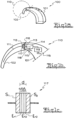
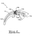
- a BTE device 100 consisting of a BTE body 101 and an attached earhook 102 is shown. It is preferred that the electromagnetic antenna system 110 is located on the upper part of the BTE device 100. Although alternative constructions are envisioned.
- the antenna system 110 includes a number of parts:
- the feeder point of the second antenna element 114 is able to be connected by a PCB track, preferably using a strip-line or a second pole element (dipole antenna) in the body of the BTE 101 (not shown) with a characteristic impedance of between 30 and 100 Ohms.
- the electrical conductive materials within the BTE device 100 are separated from each other by dielectric material.
- the BTE shell device is often formed by hard and rigid polymer material such as polymerized acrylates or medical grade hypoallergenic plastic shell materials with nano coating.
- the earhook is made of softer polymer materials such as flexible polyvinyl chloride or flexible silicon rubbers.
- the dielectric is not necessarily required to be formed of plastic materials or silicon rubbers from which respectively the BTE enclosure 101 or earhook 102 could be formed.
- dielectric materials may include ceramic materials or polytetrafluoroethylene (PTFE/Teflon TM ).
- the dielectric can be a thin film, layer, or durable coating placed upon the conductive material.
- coatings may include PTFE coatings, crystal clear film coatings, metal oxides (such as barium titanium oxide), and ceramic coatings.
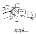
- alternative constructions may be provided in which the first dielectric material 112 or second dielectric material 113 is absent or removed.
- Figure 4 illustrates an embodiment where the second dielectric material is absent.
- the second antenna element 144 could be for example a bolt or a press-stud.
- Embedding a part of the antenna in the earhook 102 not only results in a simpler production process for the body portion of the BTE device 101, but also improves the overall antenna efficiency/gain.
- the effective antenna height and/or antenna conversion factors improve.
- a physically shorter antenna could also be placed in resonance by adding an inductance in series with the feeder line, effectively replacing the missing antenna length in order to obtain ⁇ /4, such an arrangement decreases the overall efficiency of the antenna arrangement.
- the first and/or second antenna elements 111, 114 may be fitted entirely within the earhook 102 and the body portion of the BTE device 101 respectively, advantageously providing additional protection to the antenna elements 111, 114 and allowing the body portion of the BTE device 101 and/or the earhook 102 to be more aesthetically pleasing.
- the surfaces of both conductive parts facing each other may be considered as plates 117 of a capacitor, with a distance 'd' separating the plates.
- the dielectric of the capacitor may be any material residing between the two conductive plates. It could be a combination of a maximum of three different types of stacked dielectric materials: ⁇ r1 . ⁇ r0 and ⁇ r2 .
- Each dielectric of the stack can be represented as an individual capacitor in series (C S1 . C S0, C S2 ):
- the total length of the antenna system is mostly determined by the operation frequency. Accordingly, to obtain good efficiency, it is desirable to place the antenna in resonance, resulting in no imaginary impedance part. Otherwise, the antenna impedance is required to be complex and conjugated to its source impedance.
- a series inductance XL reactive inductance
- This can be achieved by a matching circuit or increasing the length of one of the antenna elements.
- antenna length antenna length in free space ⁇ avg , environment
- the conductive antenna elements 111, 114 may have different geometric shapes as required to suit the earhook 102 and/or the wearer, for example, a bended cone shape for the first antenna element 111.
- one of the first or second antenna elements 111, 114 may be formed with a projecting portion at one end that is adapted to co-operate with a projection receiving portion formed at one end of the other of the first or second antenna elements 111.14.
- Such configurations advantageously allow the surface area of capacitor plates 117 of the first and second antenna elements 111, 114 to be maximised, resulting in a more efficient and reliable capacitive connection between the elements.
- the surface areas of the capacitor plates 117 can be increased in size by using curved surfaces on each of the capacitor plates. It will be appreciated that other surface increasing configuration such as cooperating triangular shapes on surface each of the capacitor plates 117 may also be used. Such configurations provide a higher capacitance and allow a more reliable coupling to be obtained, without the need for the diameter of the earhook 102 to be increased.
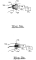
- the capacitor may be formed by a cylindrical conductive hollow element 121 inside the earhook 102, capacitively coupled to the second cylindrical antenna element 124 in the body of the BTE device.
- the capacitor may be formed by a cylindrical conductive hollow element inside the body of the BTE device, capacitively coupled to the cylindrical antenna element 131 inside the earhook 102.
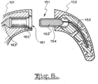
- FIG. 6 One implementation of the present invention, illustrated in Figure 6 includes an earhook 102 with an insulated projection 151 formed at one face and adapted to be fitted into a conductive receptacle portion 161 on the respective face of a BTE device 101.
- the projection 151 of the earhook includes a conductive insert 152 surrounded by insulating material 154 ( ⁇ rl ).
- the conductive insert 152 is connected to a conductive wire 153 provided within a channel formed in the earhook 102, thereby forming a first antenna element.
- the receptacle 161 in the body of the BTE device 101 is in the form of a follow cylinder 162 of a size suitable to fit the projection 151 of the earhook, and is connected to the PCB track 163 in the body of the BTE device 101, thereby forming a second antenna element.
- the first and second antenna elements are electrically coupled together by a capacitive connection, effectively forming a single antenna.
- This implementation allows for a larger surface area S and a lower capacitive reactance may be obtained.
- the implementation shown in Figure 6 may be configured with the following dimensions to operate at 2.4GHz.
Landscapes
- Health & Medical Sciences (AREA)
- Physics & Mathematics (AREA)
- Nuclear Medicine, Radiotherapy & Molecular Imaging (AREA)
- Engineering & Computer Science (AREA)
- Biomedical Technology (AREA)
- Radiology & Medical Imaging (AREA)
- Life Sciences & Earth Sciences (AREA)
- Animal Behavior & Ethology (AREA)
- General Health & Medical Sciences (AREA)
- Public Health (AREA)
- Veterinary Medicine (AREA)
- Acoustics & Sound (AREA)
- Electromagnetism (AREA)
- Support Of Aerials (AREA)
- Details Of Aerials (AREA)
Claims (5)
- Dispositif placé derrière l'oreille (BTE) pour transmettre et/ou recevoir des informations par l'intermédiaire d'une fréquence radio, ledit dispositif BTE comprenant :une partie de corps incluant un premier élément d'antenne ajusté dans la partie de corps du dispositif BTE ; etun crochet auriculaire incluant un second élément d'antenne ajusté dans le crochet auriculaire, caractérisé en ce que lesdits premier et second éléments d'antenne sont couplés électriquement ensemble par une connexion capacitive de sorte qu'un élément d'antenne est capable de prolonger le fonctionnement de l'autre élément d'antenne,dans lequel le crochet auriculaire et/ou la partie de corps du dispositif BTE sont ajustés avec des moyens permettant un démontage mécanique du crochet auriculaire par rapport à la partie de corps du dispositif BTE.
- Dispositif BTE selon la revendication 1, dans lequel le dispositif BTE est adapté à transmettre des informations à un implant et à recevoir des informations de celui-ci.
- Dispositif BTE selon l'une quelconque des revendications précédentes, dans lequel le dispositif BTE est adapté à transmettre des informations à un ou plusieurs autres dispositifs BTE et à recevoir des informations de celui-ci ou de ceux-ci.
- Dispositif BTE selon l'une quelconque des revendications précédentes, dans lequel un élément du premier ou du second élément d'antenne est muni d'une partie de projection à une extrémité qui est adaptée à coopérer avec une partie de réception de projection formée à une extrémité de l'autre du premier ou du second élément d'antenne.
- Dispositif BTE selon la revendication 4, dans lequel la partie de projection et la partie de réception de projection sont prévues chacune au niveau de la surface d'une plaque de condensateur.
Applications Claiming Priority (2)
| Application Number | Priority Date | Filing Date | Title |
|---|---|---|---|
| AU2008901474A AU2008901474A0 (en) | 2008-03-28 | Antenna for behind-the-ear (BTE) devices | |
| PCT/AU2009/000352 WO2009117778A1 (fr) | 2008-03-28 | 2009-03-26 | Antenne pour dispositifs placés derrière l'oreille (bte) |
Publications (4)
| Publication Number | Publication Date |
|---|---|
| EP2265331A1 EP2265331A1 (fr) | 2010-12-29 |
| EP2265331A4 EP2265331A4 (fr) | 2011-03-23 |
| EP2265331B1 EP2265331B1 (fr) | 2016-03-23 |
| EP2265331B2 true EP2265331B2 (fr) | 2025-03-19 |
Family
ID=41112860
Family Applications (1)
| Application Number | Title | Priority Date | Filing Date |
|---|---|---|---|
| EP09725199.5A Active EP2265331B2 (fr) | 2008-03-28 | 2009-03-26 | Antenne pour dispositifs placés derrière l'oreille (bte) |
Country Status (3)
| Country | Link |
|---|---|
| US (1) | US9295848B2 (fr) |
| EP (1) | EP2265331B2 (fr) |
| WO (1) | WO2009117778A1 (fr) |
Families Citing this family (42)
| Publication number | Priority date | Publication date | Assignee | Title |
|---|---|---|---|---|
| US8934984B2 (en) | 2007-05-31 | 2015-01-13 | Cochlear Limited | Behind-the-ear (BTE) prosthetic device with antenna |
| WO2010138856A1 (fr) | 2009-05-29 | 2010-12-02 | Abbott Diabetes Care Inc. | Systèmes d'antenne de dispositif médical comportant des configurations d'antenne externe |
| EP2725655B1 (fr) | 2010-10-12 | 2021-07-07 | GN Hearing A/S | Prothèse auditive à placer derrière l'oreille avec une antenne améliorée |
| DK2628210T3 (en) | 2010-10-12 | 2019-04-01 | Gn Hearing As | Hearing aid comprising an antenna device |
| EP2458675B1 (fr) | 2010-10-12 | 2017-12-06 | GN Hearing A/S | Aide auditive avec antenne |
| US9319807B2 (en) | 2012-02-28 | 2016-04-19 | Cochlear Limited | Device with combined antenna and transducer |
| EP3151585B1 (fr) * | 2012-03-16 | 2018-08-22 | Sonova AG | Module d'antenne pour un dispositif auditif, embout et dispositif auditif doté d'un tel module d'antenne |
| US9554219B2 (en) | 2012-07-06 | 2017-01-24 | Gn Resound A/S | BTE hearing aid having a balanced antenna |
| DK201270411A (en) | 2012-07-06 | 2014-01-07 | Gn Resound As | BTE hearing aid having two driven antennas |
| DK201270410A (en) | 2012-07-06 | 2014-01-07 | Gn Resound As | BTE hearing aid with an antenna partition plane |
| DK2750409T3 (da) * | 2012-12-28 | 2020-05-18 | Gn Hearing As | Dipolantenne til et høreapparat |
| US9237404B2 (en) | 2012-12-28 | 2016-01-12 | Gn Resound A/S | Dipole antenna for a hearing aid |
| US10985447B2 (en) | 2013-08-02 | 2021-04-20 | Gn Hearing A/S | Antenna device |
| EP3200480B1 (fr) | 2013-09-19 | 2020-03-11 | Oticon A/s | Prothèse auditive avec antenne intégrée |
| KR102092857B1 (ko) * | 2013-10-25 | 2020-03-25 | 삼성전자주식회사 | 청각 기기용 누설파 안테나 |
| US9686621B2 (en) | 2013-11-11 | 2017-06-20 | Gn Hearing A/S | Hearing aid with an antenna |
| US9883295B2 (en) | 2013-11-11 | 2018-01-30 | Gn Hearing A/S | Hearing aid with an antenna |
| US9237405B2 (en) | 2013-11-11 | 2016-01-12 | Gn Resound A/S | Hearing aid with an antenna |
| US9408003B2 (en) | 2013-11-11 | 2016-08-02 | Gn Resound A/S | Hearing aid with an antenna |
| DE102014200917A1 (de) | 2014-01-20 | 2015-07-23 | Siemens Medical Instruments Pte. Ltd. | HdO-Hörinstrument mit Gehäuse und Schallschlauch |
| US10595138B2 (en) * | 2014-08-15 | 2020-03-17 | Gn Hearing A/S | Hearing aid with an antenna |
| EP3227835B1 (fr) | 2014-12-02 | 2020-09-16 | Sensormatic Electronics, LLC | Étiquettes d'identification par radiofréquence (rfid) passives ayant des circuits intégrés utilisant une technologie de sous-seuil |
| US9384607B1 (en) | 2014-12-03 | 2016-07-05 | Tyco Fire & Security Gmbh | Access control system |
| US9831724B2 (en) | 2014-12-02 | 2017-11-28 | Tyco Fire & Security Gmbh | Access control system using a wearable access sensory implementing an energy harvesting technique |
| US9384608B2 (en) | 2014-12-03 | 2016-07-05 | Tyco Fire & Security Gmbh | Dual level human identification and location system |
| DK3664473T3 (da) * | 2015-12-14 | 2021-08-16 | Gn Hearing As | Høreapparat |
| US9710978B1 (en) | 2016-03-15 | 2017-07-18 | Tyco Fire & Security Gmbh | Access control system using optical communication protocol |
| EP3226582A1 (fr) * | 2016-03-29 | 2017-10-04 | Oticon Medical A/S | Dispositif auditif comprenant des moyens de prise modulaire |
| US9824559B2 (en) | 2016-04-07 | 2017-11-21 | Tyco Fire & Security Gmbh | Security sensing method and apparatus |
| US9949014B2 (en) * | 2016-06-13 | 2018-04-17 | Peag, LLC | Wireless pair of earbuds |
| US10051388B2 (en) | 2016-09-21 | 2018-08-14 | Starkey Laboratories, Inc. | Radio frequency antenna for an in-the-ear hearing device |
| CN106454607A (zh) * | 2016-12-05 | 2017-02-22 | 深圳市科奈信科技有限公司 | 一种无线蓝牙耳机 |
| EP3591996B1 (fr) * | 2018-07-03 | 2024-10-09 | Oticon A/s | Dispositif auditif comprenant une partie d'antenne externe et une partie d'antenne interne |
| DK3343955T3 (en) | 2016-12-29 | 2022-08-29 | Oticon As | Anordning til et høreapparat |
| EP3343953B1 (fr) | 2016-12-29 | 2022-07-06 | Oticon A/s | Dispositif auditif avec une antenne externe ainsi qu'un element interne parasite |
| US10791403B2 (en) * | 2017-07-18 | 2020-09-29 | Cochlear Limited | Ear band apparatus |
| US10674282B2 (en) * | 2017-07-18 | 2020-06-02 | Cochlear Limited | Safety ear hook apparatus |
| US11116984B2 (en) * | 2017-09-08 | 2021-09-14 | Advanced Bionics Ag | Extended length antenna assembly for use within a multi-component system |
| EP4297197A3 (fr) * | 2017-12-22 | 2024-03-06 | GN Hearing A/S | Connecteur d'une prothèse auditive |
| US10979828B2 (en) | 2018-06-05 | 2021-04-13 | Starkey Laboratories, Inc. | Ear-worn electronic device incorporating chip antenna loading of antenna structure |
| US10931005B2 (en) * | 2018-10-29 | 2021-02-23 | Starkey Laboratories, Inc. | Hearing device incorporating a primary antenna in conjunction with a chip antenna |
| US11627420B2 (en) | 2021-05-14 | 2023-04-11 | Bose Corporation | Loop antenna for hearing aid |
Citations (8)
| Publication number | Priority date | Publication date | Assignee | Title |
|---|---|---|---|---|
| US5995064A (en) † | 1996-06-20 | 1999-11-30 | Kabushiki Kaisha Yokowa, Also Trading As Yokowo Co., Ltd. | Antenna having a returned portion forming a portion arranged in parallel to the longitudinal antenna direction |
| US20030152243A1 (en) † | 2000-01-07 | 2003-08-14 | Julstrom Stephen D. | Multi-coil coupling system for hearing aid applications |
| US20040138723A1 (en) † | 2003-01-10 | 2004-07-15 | Crista Malick | Systems, devices, and methods of wireless intrabody communication |
| US20040151337A1 (en) † | 2003-01-30 | 2004-08-05 | Shary Nassimi | Wireless ear-piece with conductive case |
| US20040201527A1 (en) † | 2003-04-08 | 2004-10-14 | Hani Mohammad Bani | Variable multi-band planar antenna assembly |
| US7026999B2 (en) † | 2002-12-06 | 2006-04-11 | Sharp Kabushiki Kaisha | Pattern antenna |
| US20060227989A1 (en) † | 2005-03-28 | 2006-10-12 | Starkey Laboratories, Inc. | Antennas for hearing aids |
| EP2076065A1 (fr) † | 2007-12-27 | 2009-07-01 | Oticon A/S | Dispositif auditif et procédé pour la réception sans fil et/ou l'envoi de données |
Family Cites Families (13)
| Publication number | Priority date | Publication date | Assignee | Title |
|---|---|---|---|---|
| US5606621A (en) | 1995-06-14 | 1997-02-25 | Siemens Hearing Instruments, Inc. | Hybrid behind-the-ear and completely-in-canal hearing aid |
| ATE277672T1 (de) * | 1997-08-01 | 2004-10-15 | Mann Alfred E Found Scient Res | Implantierbare einrichtung mit verbesserter anordnung zur ladung der batterie und zur energiezufuhr |
| US6748094B1 (en) * | 2000-03-03 | 2004-06-08 | Advanced Bionics Corporation | Connector system for BTE hearing devices |
| US7881800B2 (en) * | 2002-03-08 | 2011-02-01 | Cochlear Limited | Cochlear implant having a repositionable implantable housing |
| US7142926B2 (en) * | 2002-08-30 | 2006-11-28 | Advanced Bionics Corporation | Quick connect earhook system for BTE devices |
| US7349741B2 (en) * | 2002-10-11 | 2008-03-25 | Advanced Bionics, Llc | Cochlear implant sound processor with permanently integrated replenishable power source |
| US20060184212A1 (en) * | 2004-05-07 | 2006-08-17 | Faltys Michael A | Cochlear Stimulation Device |
| JP2006301827A (ja) * | 2005-04-19 | 2006-11-02 | Aruze Corp | 非接触icカードシステム、並びに非接触icカードの取付体 |
| US7613522B2 (en) * | 2006-06-09 | 2009-11-03 | Cardiac Pacemakers, Inc. | Multi-antenna for an implantable medical device |
| KR100781228B1 (ko) | 2006-11-13 | 2007-11-30 | 삼성전자주식회사 | 내장형 안테나 모듈을 갖는 블루투스 헤드셋 |
| US8934984B2 (en) * | 2007-05-31 | 2015-01-13 | Cochlear Limited | Behind-the-ear (BTE) prosthetic device with antenna |
| US8972021B2 (en) * | 2008-03-04 | 2015-03-03 | Cardiac Pacemakers, Inc. | Detachable helical antenna for implantable medical device |
| US7917226B2 (en) * | 2008-04-23 | 2011-03-29 | Enteromedics Inc. | Antenna arrangements for implantable therapy device |
-
2009
- 2009-03-26 EP EP09725199.5A patent/EP2265331B2/fr active Active
- 2009-03-26 WO PCT/AU2009/000352 patent/WO2009117778A1/fr not_active Ceased
- 2009-03-26 US US12/935,277 patent/US9295848B2/en active Active
Patent Citations (8)
| Publication number | Priority date | Publication date | Assignee | Title |
|---|---|---|---|---|
| US5995064A (en) † | 1996-06-20 | 1999-11-30 | Kabushiki Kaisha Yokowa, Also Trading As Yokowo Co., Ltd. | Antenna having a returned portion forming a portion arranged in parallel to the longitudinal antenna direction |
| US20030152243A1 (en) † | 2000-01-07 | 2003-08-14 | Julstrom Stephen D. | Multi-coil coupling system for hearing aid applications |
| US7026999B2 (en) † | 2002-12-06 | 2006-04-11 | Sharp Kabushiki Kaisha | Pattern antenna |
| US20040138723A1 (en) † | 2003-01-10 | 2004-07-15 | Crista Malick | Systems, devices, and methods of wireless intrabody communication |
| US20040151337A1 (en) † | 2003-01-30 | 2004-08-05 | Shary Nassimi | Wireless ear-piece with conductive case |
| US20040201527A1 (en) † | 2003-04-08 | 2004-10-14 | Hani Mohammad Bani | Variable multi-band planar antenna assembly |
| US20060227989A1 (en) † | 2005-03-28 | 2006-10-12 | Starkey Laboratories, Inc. | Antennas for hearing aids |
| EP2076065A1 (fr) † | 2007-12-27 | 2009-07-01 | Oticon A/S | Dispositif auditif et procédé pour la réception sans fil et/ou l'envoi de données |
Also Published As
| Publication number | Publication date |
|---|---|
| EP2265331A4 (fr) | 2011-03-23 |
| US9295848B2 (en) | 2016-03-29 |
| US20110022121A1 (en) | 2011-01-27 |
| EP2265331B1 (fr) | 2016-03-23 |
| EP2265331A1 (fr) | 2010-12-29 |
| WO2009117778A1 (fr) | 2009-10-01 |
Similar Documents
| Publication | Publication Date | Title |
|---|---|---|
| EP2265331B2 (fr) | Antenne pour dispositifs placés derrière l'oreille (bte) | |
| US12311171B2 (en) | Acoustic output device with antenna | |
| US7512448B2 (en) | Electrode placement for wireless intrabody communication between components of a hearing system | |
| EP3648478B1 (fr) | Dispositif auditif comprenant une antenne primaire en conjonction avec une antenne à puce | |
| US10804599B2 (en) | BTE hearing instrument comprising a loop antenna | |
| EP1362614A1 (fr) | Antenne à plaque implantable | |
| EP2349471B1 (fr) | Dispositif médical implantable doté d'une antenne perfectionnée | |
| US20050099341A1 (en) | Antenna for a wireless hearing aid system | |
| US8947301B2 (en) | Multi-band loaded antenna | |
| US10957970B2 (en) | Systems and methods for incorporating a patch antenna in an implantable medical device | |
| CN111050843A (zh) | 具有多频段环形天线的可植入医疗装置 | |
| CN116962949A (zh) | 听力设备、特别是耳内式听力设备 | |
| US20200015023A1 (en) | Bte hearing instrument comprising an open-end transmission line antenna | |
| KR20170090026A (ko) | 페라이트 적층 유전체 기판을 구비한 인체 삽입형 안테나 | |
| Iqbal et al. | Self-Diplexing Implantable Antenna with Independently Controllable Bands | |
| WO2024228078A1 (fr) | Implant avec bobine d'induction et antenne avec sommet | |
| KR20160092827A (ko) | 인체 삽입형 안테나 |
Legal Events
| Date | Code | Title | Description |
|---|---|---|---|
| PUAI | Public reference made under article 153(3) epc to a published international application that has entered the european phase |
Free format text: ORIGINAL CODE: 0009012 |
|
| 17P | Request for examination filed |
Effective date: 20101022 |
|
| AK | Designated contracting states |
Kind code of ref document: A1 Designated state(s): AT BE BG CH CY CZ DE DK EE ES FI FR GB GR HR HU IE IS IT LI LT LU LV MC MK MT NL NO PL PT RO SE SI SK TR |
|
| AX | Request for extension of the european patent |
Extension state: AL BA RS |
|
| A4 | Supplementary search report drawn up and despatched |
Effective date: 20110218 |
|
| DAX | Request for extension of the european patent (deleted) | ||
| RAP1 | Party data changed (applicant data changed or rights of an application transferred) |
Owner name: COCHLEAR LIMITED |
|
| RIC1 | Information provided on ipc code assigned before grant |
Ipc: A61N 1/372 20060101ALI20150731BHEP Ipc: H04R 25/00 20060101ALN20150731BHEP Ipc: A61N 1/375 20060101AFI20150731BHEP |
|
| GRAP | Despatch of communication of intention to grant a patent |
Free format text: ORIGINAL CODE: EPIDOSNIGR1 |
|
| INTG | Intention to grant announced |
Effective date: 20150918 |
|
| GRAS | Grant fee paid |
Free format text: ORIGINAL CODE: EPIDOSNIGR3 |
|
| GRAA | (expected) grant |
Free format text: ORIGINAL CODE: 0009210 |
|
| AK | Designated contracting states |
Kind code of ref document: B1 Designated state(s): AT BE BG CH CY CZ DE DK EE ES FI FR GB GR HR HU IE IS IT LI LT LU LV MC MK MT NL NO PL PT RO SE SI SK TR |
|
| REG | Reference to a national code |
Ref country code: GB Ref legal event code: FG4D |
|
| REG | Reference to a national code |
Ref country code: CH Ref legal event code: EP |
|
| REG | Reference to a national code |
Ref country code: FR Ref legal event code: PLFP Year of fee payment: 8 Ref country code: FR Ref legal event code: PLFP Year of fee payment: 9 |
|
| REG | Reference to a national code |
Ref country code: AT Ref legal event code: REF Ref document number: 782539 Country of ref document: AT Kind code of ref document: T Effective date: 20160415 |
|
| REG | Reference to a national code |
Ref country code: IE Ref legal event code: FG4D |
|
| REG | Reference to a national code |
Ref country code: DE Ref legal event code: R096 Ref document number: 602009037024 Country of ref document: DE |
|
| REG | Reference to a national code |
Ref country code: LT Ref legal event code: MG4D |
|
| REG | Reference to a national code |
Ref country code: NL Ref legal event code: MP Effective date: 20160323 |
|
| PG25 | Lapsed in a contracting state [announced via postgrant information from national office to epo] |
Ref country code: FI Free format text: LAPSE BECAUSE OF FAILURE TO SUBMIT A TRANSLATION OF THE DESCRIPTION OR TO PAY THE FEE WITHIN THE PRESCRIBED TIME-LIMIT Effective date: 20160323 Ref country code: NO Free format text: LAPSE BECAUSE OF FAILURE TO SUBMIT A TRANSLATION OF THE DESCRIPTION OR TO PAY THE FEE WITHIN THE PRESCRIBED TIME-LIMIT Effective date: 20160623 Ref country code: GR Free format text: LAPSE BECAUSE OF FAILURE TO SUBMIT A TRANSLATION OF THE DESCRIPTION OR TO PAY THE FEE WITHIN THE PRESCRIBED TIME-LIMIT Effective date: 20160624 |
|
| REG | Reference to a national code |
Ref country code: AT Ref legal event code: MK05 Ref document number: 782539 Country of ref document: AT Kind code of ref document: T Effective date: 20160323 |
|
| PG25 | Lapsed in a contracting state [announced via postgrant information from national office to epo] |
Ref country code: LV Free format text: LAPSE BECAUSE OF FAILURE TO SUBMIT A TRANSLATION OF THE DESCRIPTION OR TO PAY THE FEE WITHIN THE PRESCRIBED TIME-LIMIT Effective date: 20160323 Ref country code: NL Free format text: LAPSE BECAUSE OF FAILURE TO SUBMIT A TRANSLATION OF THE DESCRIPTION OR TO PAY THE FEE WITHIN THE PRESCRIBED TIME-LIMIT Effective date: 20160323 Ref country code: SE Free format text: LAPSE BECAUSE OF FAILURE TO SUBMIT A TRANSLATION OF THE DESCRIPTION OR TO PAY THE FEE WITHIN THE PRESCRIBED TIME-LIMIT Effective date: 20160323 Ref country code: LT Free format text: LAPSE BECAUSE OF FAILURE TO SUBMIT A TRANSLATION OF THE DESCRIPTION OR TO PAY THE FEE WITHIN THE PRESCRIBED TIME-LIMIT Effective date: 20160323 Ref country code: BE Free format text: LAPSE BECAUSE OF NON-PAYMENT OF DUE FEES Effective date: 20160331 |
|
| PG25 | Lapsed in a contracting state [announced via postgrant information from national office to epo] |
Ref country code: PL Free format text: LAPSE BECAUSE OF FAILURE TO SUBMIT A TRANSLATION OF THE DESCRIPTION OR TO PAY THE FEE WITHIN THE PRESCRIBED TIME-LIMIT Effective date: 20160323 Ref country code: IS Free format text: LAPSE BECAUSE OF FAILURE TO SUBMIT A TRANSLATION OF THE DESCRIPTION OR TO PAY THE FEE WITHIN THE PRESCRIBED TIME-LIMIT Effective date: 20160723 Ref country code: EE Free format text: LAPSE BECAUSE OF FAILURE TO SUBMIT A TRANSLATION OF THE DESCRIPTION OR TO PAY THE FEE WITHIN THE PRESCRIBED TIME-LIMIT Effective date: 20160323 |
|
| REG | Reference to a national code |
Ref country code: CH Ref legal event code: PL |
|
| PG25 | Lapsed in a contracting state [announced via postgrant information from national office to epo] |
Ref country code: RO Free format text: LAPSE BECAUSE OF FAILURE TO SUBMIT A TRANSLATION OF THE DESCRIPTION OR TO PAY THE FEE WITHIN THE PRESCRIBED TIME-LIMIT Effective date: 20160323 Ref country code: ES Free format text: LAPSE BECAUSE OF FAILURE TO SUBMIT A TRANSLATION OF THE DESCRIPTION OR TO PAY THE FEE WITHIN THE PRESCRIBED TIME-LIMIT Effective date: 20160323 Ref country code: AT Free format text: LAPSE BECAUSE OF FAILURE TO SUBMIT A TRANSLATION OF THE DESCRIPTION OR TO PAY THE FEE WITHIN THE PRESCRIBED TIME-LIMIT Effective date: 20160323 Ref country code: SK Free format text: LAPSE BECAUSE OF FAILURE TO SUBMIT A TRANSLATION OF THE DESCRIPTION OR TO PAY THE FEE WITHIN THE PRESCRIBED TIME-LIMIT Effective date: 20160323 Ref country code: PT Free format text: LAPSE BECAUSE OF FAILURE TO SUBMIT A TRANSLATION OF THE DESCRIPTION OR TO PAY THE FEE WITHIN THE PRESCRIBED TIME-LIMIT Effective date: 20160725 Ref country code: CZ Free format text: LAPSE BECAUSE OF FAILURE TO SUBMIT A TRANSLATION OF THE DESCRIPTION OR TO PAY THE FEE WITHIN THE PRESCRIBED TIME-LIMIT Effective date: 20160323 |
|
| REG | Reference to a national code |
Ref country code: DE Ref legal event code: R026 Ref document number: 602009037024 Country of ref document: DE |
|
| REG | Reference to a national code |
Ref country code: IE Ref legal event code: MM4A |
|
| PG25 | Lapsed in a contracting state [announced via postgrant information from national office to epo] |
Ref country code: IT Free format text: LAPSE BECAUSE OF FAILURE TO SUBMIT A TRANSLATION OF THE DESCRIPTION OR TO PAY THE FEE WITHIN THE PRESCRIBED TIME-LIMIT Effective date: 20160323 Ref country code: BE Free format text: LAPSE BECAUSE OF FAILURE TO SUBMIT A TRANSLATION OF THE DESCRIPTION OR TO PAY THE FEE WITHIN THE PRESCRIBED TIME-LIMIT Effective date: 20160323 |
|
| PLBI | Opposition filed |
Free format text: ORIGINAL CODE: 0009260 |
|
| PG25 | Lapsed in a contracting state [announced via postgrant information from national office to epo] |
Ref country code: DK Free format text: LAPSE BECAUSE OF FAILURE TO SUBMIT A TRANSLATION OF THE DESCRIPTION OR TO PAY THE FEE WITHIN THE PRESCRIBED TIME-LIMIT Effective date: 20160323 Ref country code: CH Free format text: LAPSE BECAUSE OF NON-PAYMENT OF DUE FEES Effective date: 20160331 Ref country code: IE Free format text: LAPSE BECAUSE OF NON-PAYMENT OF DUE FEES Effective date: 20160326 Ref country code: LI Free format text: LAPSE BECAUSE OF NON-PAYMENT OF DUE FEES Effective date: 20160331 |
|
| PLAX | Notice of opposition and request to file observation + time limit sent |
Free format text: ORIGINAL CODE: EPIDOSNOBS2 |
|
| 26 | Opposition filed |
Opponent name: K/S HIMPP Effective date: 20161223 |
|
| PG25 | Lapsed in a contracting state [announced via postgrant information from national office to epo] |
Ref country code: BG Free format text: LAPSE BECAUSE OF FAILURE TO SUBMIT A TRANSLATION OF THE DESCRIPTION OR TO PAY THE FEE WITHIN THE PRESCRIBED TIME-LIMIT Effective date: 20160623 |
|
| GBPC | Gb: european patent ceased through non-payment of renewal fee |
Effective date: 20160623 |
|
| PG25 | Lapsed in a contracting state [announced via postgrant information from national office to epo] |
Ref country code: GB Free format text: LAPSE BECAUSE OF NON-PAYMENT OF DUE FEES Effective date: 20160623 Ref country code: SI Free format text: LAPSE BECAUSE OF FAILURE TO SUBMIT A TRANSLATION OF THE DESCRIPTION OR TO PAY THE FEE WITHIN THE PRESCRIBED TIME-LIMIT Effective date: 20160323 |
|
| PLBB | Reply of patent proprietor to notice(s) of opposition received |
Free format text: ORIGINAL CODE: EPIDOSNOBS3 |
|
| REG | Reference to a national code |
Ref country code: FR Ref legal event code: PLFP Year of fee payment: 9 |
|
| PG25 | Lapsed in a contracting state [announced via postgrant information from national office to epo] |
Ref country code: MT Free format text: LAPSE BECAUSE OF FAILURE TO SUBMIT A TRANSLATION OF THE DESCRIPTION OR TO PAY THE FEE WITHIN THE PRESCRIBED TIME-LIMIT Effective date: 20160323 |
|
| REG | Reference to a national code |
Ref country code: FR Ref legal event code: PLFP Year of fee payment: 10 |
|
| PG25 | Lapsed in a contracting state [announced via postgrant information from national office to epo] |
Ref country code: CY Free format text: LAPSE BECAUSE OF FAILURE TO SUBMIT A TRANSLATION OF THE DESCRIPTION OR TO PAY THE FEE WITHIN THE PRESCRIBED TIME-LIMIT Effective date: 20160323 Ref country code: HU Free format text: LAPSE BECAUSE OF FAILURE TO SUBMIT A TRANSLATION OF THE DESCRIPTION OR TO PAY THE FEE WITHIN THE PRESCRIBED TIME-LIMIT; INVALID AB INITIO Effective date: 20090326 |
|
| PG25 | Lapsed in a contracting state [announced via postgrant information from national office to epo] |
Ref country code: MC Free format text: LAPSE BECAUSE OF FAILURE TO SUBMIT A TRANSLATION OF THE DESCRIPTION OR TO PAY THE FEE WITHIN THE PRESCRIBED TIME-LIMIT Effective date: 20160323 Ref country code: LU Free format text: LAPSE BECAUSE OF NON-PAYMENT OF DUE FEES Effective date: 20160326 Ref country code: TR Free format text: LAPSE BECAUSE OF FAILURE TO SUBMIT A TRANSLATION OF THE DESCRIPTION OR TO PAY THE FEE WITHIN THE PRESCRIBED TIME-LIMIT Effective date: 20160323 Ref country code: MK Free format text: LAPSE BECAUSE OF FAILURE TO SUBMIT A TRANSLATION OF THE DESCRIPTION OR TO PAY THE FEE WITHIN THE PRESCRIBED TIME-LIMIT Effective date: 20160323 Ref country code: MT Free format text: LAPSE BECAUSE OF FAILURE TO SUBMIT A TRANSLATION OF THE DESCRIPTION OR TO PAY THE FEE WITHIN THE PRESCRIBED TIME-LIMIT Effective date: 20160331 Ref country code: HR Free format text: LAPSE BECAUSE OF FAILURE TO SUBMIT A TRANSLATION OF THE DESCRIPTION OR TO PAY THE FEE WITHIN THE PRESCRIBED TIME-LIMIT Effective date: 20160323 |
|
| APAH | Appeal reference modified |
Free format text: ORIGINAL CODE: EPIDOSCREFNO |
|
| APAW | Appeal reference deleted |
Free format text: ORIGINAL CODE: EPIDOSDREFNO |
|
| APBM | Appeal reference recorded |
Free format text: ORIGINAL CODE: EPIDOSNREFNO |
|
| APBP | Date of receipt of notice of appeal recorded |
Free format text: ORIGINAL CODE: EPIDOSNNOA2O |
|
| PLAB | Opposition data, opponent's data or that of the opponent's representative modified |
Free format text: ORIGINAL CODE: 0009299OPPO |
|
| R26 | Opposition filed (corrected) |
Opponent name: K/S HIMPP Effective date: 20161223 |
|
| APBU | Appeal procedure closed |
Free format text: ORIGINAL CODE: EPIDOSNNOA9O |
|
| P01 | Opt-out of the competence of the unified patent court (upc) registered |
Effective date: 20230505 |
|
| PLAY | Examination report in opposition despatched + time limit |
Free format text: ORIGINAL CODE: EPIDOSNORE2 |
|
| PLBC | Reply to examination report in opposition received |
Free format text: ORIGINAL CODE: EPIDOSNORE3 |
|
| PUAH | Patent maintained in amended form |
Free format text: ORIGINAL CODE: 0009272 |
|
| STAA | Information on the status of an ep patent application or granted ep patent |
Free format text: STATUS: PATENT MAINTAINED AS AMENDED |
|
| 27A | Patent maintained in amended form |
Effective date: 20250319 |
|
| AK | Designated contracting states |
Kind code of ref document: B2 Designated state(s): AT BE BG CH CY CZ DE DK EE ES FI FR GB GR HR HU IE IS IT LI LT LU LV MC MK MT NL NO PL PT RO SE SI SK TR |
|
| REG | Reference to a national code |
Ref country code: DE Ref legal event code: R102 Ref document number: 602009037024 Country of ref document: DE |
|
| PGFP | Annual fee paid to national office [announced via postgrant information from national office to epo] |
Ref country code: FR Payment date: 20251231 Year of fee payment: 18 |
|
| PGFP | Annual fee paid to national office [announced via postgrant information from national office to epo] |
Ref country code: DE Payment date: 20260102 Year of fee payment: 18 |