EP2265182B1 - System for ultrasonic imaging of an organ in a patient's body through a part of the patient's respiratory tract - Google Patents
System for ultrasonic imaging of an organ in a patient's body through a part of the patient's respiratory tract Download PDFInfo
- Publication number
- EP2265182B1 EP2265182B1 EP08734676.3A EP08734676A EP2265182B1 EP 2265182 B1 EP2265182 B1 EP 2265182B1 EP 08734676 A EP08734676 A EP 08734676A EP 2265182 B1 EP2265182 B1 EP 2265182B1
- Authority
- EP
- European Patent Office
- Prior art keywords
- stylet
- catheter
- inflatable member
- ultrasonic imaging
- patient
- Prior art date
- Legal status (The legal status is an assumption and is not a legal conclusion. Google has not performed a legal analysis and makes no representation as to the accuracy of the status listed.)
- Not-in-force
Links
- 238000003384 imaging method Methods 0.000 title claims description 32
- 210000002345 respiratory system Anatomy 0.000 title claims description 16
- 210000000056 organ Anatomy 0.000 title claims description 7
- 239000012530 fluid Substances 0.000 claims description 22
- 230000005540 biological transmission Effects 0.000 claims description 18
- 210000000621 bronchi Anatomy 0.000 claims description 17
- 230000002093 peripheral effect Effects 0.000 claims description 4
- 239000000463 material Substances 0.000 claims description 3
- 239000012858 resilient material Substances 0.000 claims description 3
- 210000000709 aorta Anatomy 0.000 description 11
- 210000003437 trachea Anatomy 0.000 description 10
- 239000000523 sample Substances 0.000 description 7
- 238000013175 transesophageal echocardiography Methods 0.000 description 7
- 238000002604 ultrasonography Methods 0.000 description 7
- 210000003238 esophagus Anatomy 0.000 description 4
- 238000001356 surgical procedure Methods 0.000 description 4
- 238000010521 absorption reaction Methods 0.000 description 3
- 230000033001 locomotion Effects 0.000 description 3
- 238000012986 modification Methods 0.000 description 3
- 230000004048 modification Effects 0.000 description 3
- XLYOFNOQVPJJNP-UHFFFAOYSA-N water Substances O XLYOFNOQVPJJNP-UHFFFAOYSA-N 0.000 description 3
- FAPWRFPIFSIZLT-UHFFFAOYSA-M Sodium chloride Chemical compound [Na+].[Cl-] FAPWRFPIFSIZLT-UHFFFAOYSA-M 0.000 description 2
- 210000000988 bone and bone Anatomy 0.000 description 2
- 230000002612 cardiopulmonary effect Effects 0.000 description 2
- 238000000034 method Methods 0.000 description 2
- 230000002792 vascular Effects 0.000 description 2
- 238000012800 visualization Methods 0.000 description 2
- 230000002411 adverse Effects 0.000 description 1
- 210000003484 anatomy Anatomy 0.000 description 1
- 210000002376 aorta thoracic Anatomy 0.000 description 1
- 230000000747 cardiac effect Effects 0.000 description 1
- 210000000038 chest Anatomy 0.000 description 1
- 230000001419 dependent effect Effects 0.000 description 1
- 238000011161 development Methods 0.000 description 1
- 238000002592 echocardiography Methods 0.000 description 1
- 238000012544 monitoring process Methods 0.000 description 1
- 230000007170 pathology Effects 0.000 description 1
- 238000012545 processing Methods 0.000 description 1
- 238000004904 shortening Methods 0.000 description 1
Images
Classifications
-
- A—HUMAN NECESSITIES
- A61—MEDICAL OR VETERINARY SCIENCE; HYGIENE
- A61B—DIAGNOSIS; SURGERY; IDENTIFICATION
- A61B8/00—Diagnosis using ultrasonic, sonic or infrasonic waves
- A61B8/12—Diagnosis using ultrasonic, sonic or infrasonic waves in body cavities or body tracts, e.g. by using catheters
-
- A—HUMAN NECESSITIES
- A61—MEDICAL OR VETERINARY SCIENCE; HYGIENE
- A61B—DIAGNOSIS; SURGERY; IDENTIFICATION
- A61B8/00—Diagnosis using ultrasonic, sonic or infrasonic waves
- A61B8/44—Constructional features of the ultrasonic, sonic or infrasonic diagnostic device
- A61B8/4444—Constructional features of the ultrasonic, sonic or infrasonic diagnostic device related to the probe
- A61B8/445—Details of catheter construction
-
- A—HUMAN NECESSITIES
- A61—MEDICAL OR VETERINARY SCIENCE; HYGIENE
- A61M—DEVICES FOR INTRODUCING MEDIA INTO, OR ONTO, THE BODY; DEVICES FOR TRANSDUCING BODY MEDIA OR FOR TAKING MEDIA FROM THE BODY; DEVICES FOR PRODUCING OR ENDING SLEEP OR STUPOR
- A61M25/00—Catheters; Hollow probes
- A61M25/01—Introducing, guiding, advancing, emplacing or holding catheters
- A61M25/0105—Steering means as part of the catheter or advancing means; Markers for positioning
- A61M25/0133—Tip steering devices
- A61M25/0147—Tip steering devices with movable mechanical means, e.g. pull wires
-
- A—HUMAN NECESSITIES
- A61—MEDICAL OR VETERINARY SCIENCE; HYGIENE
- A61M—DEVICES FOR INTRODUCING MEDIA INTO, OR ONTO, THE BODY; DEVICES FOR TRANSDUCING BODY MEDIA OR FOR TAKING MEDIA FROM THE BODY; DEVICES FOR PRODUCING OR ENDING SLEEP OR STUPOR
- A61M25/00—Catheters; Hollow probes
- A61M25/01—Introducing, guiding, advancing, emplacing or holding catheters
- A61M25/0105—Steering means as part of the catheter or advancing means; Markers for positioning
- A61M25/0133—Tip steering devices
- A61M25/0152—Tip steering devices with pre-shaped mechanisms, e.g. pre-shaped stylets or pre-shaped outer tubes
-
- A—HUMAN NECESSITIES
- A61—MEDICAL OR VETERINARY SCIENCE; HYGIENE
- A61M—DEVICES FOR INTRODUCING MEDIA INTO, OR ONTO, THE BODY; DEVICES FOR TRANSDUCING BODY MEDIA OR FOR TAKING MEDIA FROM THE BODY; DEVICES FOR PRODUCING OR ENDING SLEEP OR STUPOR
- A61M25/00—Catheters; Hollow probes
- A61M25/01—Introducing, guiding, advancing, emplacing or holding catheters
- A61M25/06—Body-piercing guide needles or the like
- A61M25/0662—Guide tubes
-
- A—HUMAN NECESSITIES
- A61—MEDICAL OR VETERINARY SCIENCE; HYGIENE
- A61M—DEVICES FOR INTRODUCING MEDIA INTO, OR ONTO, THE BODY; DEVICES FOR TRANSDUCING BODY MEDIA OR FOR TAKING MEDIA FROM THE BODY; DEVICES FOR PRODUCING OR ENDING SLEEP OR STUPOR
- A61M25/00—Catheters; Hollow probes
- A61M25/01—Introducing, guiding, advancing, emplacing or holding catheters
- A61M25/09—Guide wires
-
- A—HUMAN NECESSITIES
- A61—MEDICAL OR VETERINARY SCIENCE; HYGIENE
- A61M—DEVICES FOR INTRODUCING MEDIA INTO, OR ONTO, THE BODY; DEVICES FOR TRANSDUCING BODY MEDIA OR FOR TAKING MEDIA FROM THE BODY; DEVICES FOR PRODUCING OR ENDING SLEEP OR STUPOR
- A61M25/00—Catheters; Hollow probes
- A61M25/10—Balloon catheters
Definitions
- the invention relates to a system according to the preamble of claim 1.
- WO 00/53098 relates to an ultrasonic imaging method that is known as transesophageal echocardiography (TEE).
- TEE has become a widely used imaging technique for evaluating cardiac structure, function, and valvular anatomy.
- TEE has also provided a new perspective on the thoracic aorta, and there is growing evidence that the technique contributes valuable and sometimes unique information about aortic structure and pathology.
- TEE involves introducing an echo probe into the patient's esophagus and transmitting ultrasound waves across the thorax in the direction of the heart and aorta.
- visualization of the ascending aorta by internal TEE is limited by an air structure, i.e. the trachea and main left and right bronchi.
- WO 00/53098 proposes the use of a balloon that may be arranged in the trachea or in one of the bronchi and that may be filled with an ultrasonic transmission fluid, e.g. water or a saline solution in minor concentrations. Obviously, this can only be done during operative surgery, when the patient is mechanically ventilated or on cardiopulmonary bypass, since in order to be effective the balloon has to completely fill and block the trachea or bronchus.
- an ultrasonic transmission fluid e.g. water or a saline solution in minor concentrations.
- the invention relates to a system for ultrasonic imaging of an organ in a patient' s body through a part of the patient's respiratory tract according to the preamble of claim 1.
- a prior art imaging system of this type is disclosed in WO 00/53098 and US 5 190 046 .
- the ultrasonic imaging system of the present invention is distinguished from these prior art systems by the features of the characterizing portion of claim 1.
- the ultrasonic imaging system includes a short stylet, which is arranged between the inflatable member and a distal end of the catheter. Since this stylet does not extend across the inflatable member, it will not interfere with the imaging.
- the catheter may have a main lumen for filling the inflatable member with the ultrasonic transmission fluid, the stylet being arranged in this main lumen. In this way no structural modification of the catheter is required.
- the catheter may have a main lumen for filling the inflatable member with the ultrasonic transmission fluid and an additional lumen for accommodating the stylet.
- the catheter may have a main lumen for filling the inflatable member with the ultrasonic transmission fluid and the stylet may be fixedly arranged in a peripheral wall surrounding the main lumen.
- the distal end of the catheter preferably includes a tip that is shaped to facilitate positioning in the patient' s left main bronchus and the stylet is adhesively fixed to the catheter tip. In this way the stylet and tip cooperate to allow the inflatable member to be optimally positioned.
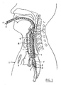
- a method for ultrasonic imaging of an organ in a patient's body 1, in particular the heart or the aorta 2, through a part of the patient's respiratory tract 3, comprises the following steps.
- an ultrasonic imaging device for instance an echo probe
- the echo probe 4 which is carried on a flexible catheter 9, is introduced into the patient's esophagus 5 ( fig. 1 ).
- another flexible catheter 6 carrying an inflatable member 7 is introduced into the respiratory tract 3.
- the inflatable member 7 is positioned at a predetermined location in the respiratory tract 3.
- the predetermined position will be in the top part of the left bronchus 8.
- the flexible catheter 6 carrying the inflatable member 7 will be guided through the patient's trachea 16 by first introducing an endotracheal tube 17 into the trachea 16. This tube 17 is somewhat stiffer than the catheter 6 and therefore easier to control. The catheter 6 is then inserted in the endotracheal tube 17. After leaving the endotracheal tube 17 the distal end 13 of the catheter 6 and the inflatable member 7 are guided into the left bronchus 8.
- the inflatable member 7 After the inflatable member 7 has been positioned, it is filled with an ultrasonic transmission fluid F through the flexible catheter 6.
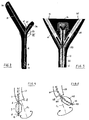
- the fluid F is injected into the catheter 6 by means of a syringe (not shown), which is connected to a fill connector 20 at the end of a fill line 21 ( fig. 2 ) .
- This fill line 21 in turn is connected to a proximal end 22 of the catheter 6 through a trident connector 23 ( fig. 3 ).
- the degree of filling of the inflatable member 7 may be visually determined by monitoring a pilot balloon 24, which is arranged at the end of a pilot line 25. This pilot line 25 is also connected to the catheter 6 through the trident connector 23.
- the echo probe 4 When the degree of inflation of the pilot balloon 24 indicates that the inflatable member 7 has been filled to such an extent that it completely covers the entire cross-sectional area of the left bronchus 8, so that no air is present between the echo probe 4 and the organ 2 to be imaged, the echo probe 4 is activated. Ultrasonic waves are then transmitted from the echo probe 4 through the transmission fluid F in the inflatable member 7 to the ascending aorta 2. Reflections from the aorta 2 are received at the echo probe 4 and transmitted through a line running through the catheter 9 to a processing and display apparatus, which does not form part of the present invention and is not shown here.
- the ultrasonic waves can travel pass the respiratory tract 3 with virtually no absorption. Consequently, very good ultrasound images of the aorta 2 may be obtained. Obviously, this can only be done during operative surgery, when the patient is mechanically ventilated or on cardiopulmonary bypass, since in order to be effective the inflatable member 7 has to completely fill and block the left bronchus 8.
- the transmission fluid F e.g. water or a saline solution in minor concentrations
- the inflatable member 7 In order to properly visualize the aorta it is important that the inflatable member 7 be positioned in precisely the right location.
- the inflatable member 7 is positioned in the respiratory tract by manipulating guide means that are attached to or integrated with the flexible catheter 6.
- these guide means are passive and include a stylet 11 that extends over the entire length of the flexible catheter 6.
- a distal end 12 of the stylet 11 extends beyond the inflatable member 7 to a distal end 13 of the catheter 6.
- a proximal end 14 of the stylet 11 protrudes from the proximal end 22 of the catheter 6 outside the patient's body 1 and extends into the center prong of the trident connector 23.
- This center prong is closed by a cap 15 carrying a valve member 26, the function of which will be described below.
- This arrangement allows the inflatable member 7 to be swiftly and accurately positioned in the respiratory tract 3, since the presence of the stylet 11 adds stiffness to the flexible catheter 6, thus improving directional control and predictability of the movement.
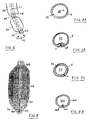
- the catheter 6 has a main lumen 27 for filling the inflatable member 7 with the ultrasonic transmission fluid F and the stylet 11 is arranged in the main lumen 27 ( fig. 7A ).
- the catheter 6 may have a main lumen 27 for the ultrasonic transmission fluid F and an additional lumen 28 for accommodating the stylet 11 ( fig. 7B ). In this way the stylet 11 does not interfere with the fluid supply function of the catheter 6.
- the stylet 11 In order to prevent the full length stylet 11 from obstructing part of the area to be imaged from view, it has to be at least partially retracted before the ultrasonic waves are transmitted from the imaging device 4. To that end the stylet 11 may be slidably arranged in either the main lumen 27 or the additional lumen 28. Although for proper imaging it would be sufficient to withdraw the stylet 11 only so far that its distal end 12 is on the proximal side of the inflatable member I1 in actual practice the stylet 11 will be completely withdrawn from the catheter 6, since it has served its purpose when the inflatable member 7 has been properly positioned.
- valve member 26 is a one-way valve that is arranged in the center prong of the trident connector 23.
- the stylet 11 may be fixedly arranged in a peripheral wall 29 surrounding the main lumen 27 of the catheter 6 ( fig. 7C ).
- a very thin stylet HA is used, which does not adversely affect the ultrasonic imaging in any substantial way, and which therefore does not have to be retracted.
- This thin stylet HA may be fixedly arranged in the catheter wall 29.
- the stylet 11 is made from a resilient material and is substantially straight. Consequently, the stylet 11 will always try to assume its original straight shape.
- the flexible catheter 6 and the stylet 11 are guided through the endotracheal tube 17, which itself follows the curvature of the trachea 16, they will have to follow the curvature of the tube 17 as well.
- the stylet 11 will return to its straight shape due to its resiliency.
- the part of the stylet 11 and the catheter 6 protruding from the distal end 18 of the tube 17 will therefore enclose an angle with an imaginary extension of the centerline CL of the tube 17. Consequently, rotating the proximal end 14 of the stylet 11 will lead to the distal end 12 describing a circular motion, which facilitates positioning of the distal end 13 of the catheter 6 at the entrance of the left bronchus 8 ( fig. 4 ).
- the stylet 111 is made from a resilient material and is preformed to conform substantially to the intended path of the catheter 106 through the respiratory tract 3. Preforming the stylet 111 may advantageously be done before it is attached to or integrated with the flexible catheter 106. In this way the catheter 106 assumes the shape of the stylet 111. When the flexible catheter 106 and the stylet 111 are guided through the endotracheal tube 117, which has less curvature than the stylet 111, they will be straightened somewhat.
- the stylet 111 will return to its curved shape due to its resiliency, again extending under an angle with respect to the extension of the centerline CL of the tube 117. Therefore, also in this embodiment rotating the proximal end 114 of the stylet 111 will result in a circular motion of its distal end 112, thus allowing the distal end 113 of the catheter 106 to be positioned at the entrance of the left bronchus 8 ( fig. 5 ).
- the stylet 211 is made from a deformable material.
- the stylet 211 will conform to the respiratory tract 3, or to the endotracheal tube 217, when the flexible catheter 206 including this stylet 211 passes through the trachea 16.
- the material of the stylet 211 will maintain the curved shape into which it was forced. Consequently, the distal end 213 of the catheter 206 will form a continuation of the curvature of the tube 217, so that it can again easily be guided to its predetermined position at the entrance of the left bronchus 8 ( fig. 6 ) by manipulating the proximal end of the stylet 211.
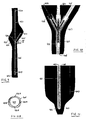
- the ultrasonic imaging system may include a short stylet 311, which may be arranged between the inflatable member 307 and the distal end 313 of the catheter 306 ( fig. 8 ), rather than a full length stylet. Since this short stylet 311 does not extend across the inflatable member 307, it will not interfere with the imaging and there is no need to retract it.
- the distal end 313 of the catheter 306 includes a tip 330 that is shaped to facilitate positioning in the patient's left main bronchus 8 and the stylet 311 is adhesively fixed to the catheter tip 330. In this way the stylet 311 and tip 330 cooperate to allow the inflatable member 307 to be optimally positioned.
- the stylet 311 does not extend beyond the distal end of the inflatable member 307, this embodiment will not have any part extending outside the patient's body 1. Positioning of the catheter 306 and the inflatable member 307 is done by manipulating the proximal end of the catheter 306. And since this stylet 311 does not have to be retracted from the catheter 306, there is no need for a special valve means.
- the guide means 410 comprise a wire 431 rather than a stylet.
- a distal end 432 of the wire 431 is eccentrically connected to the flexible catheter 406 and a proximal end 433 of the wire 431 is connected to a pulling member 434 arranged outside the patient's body 1 ( fig. 9 ).
- the wire 431 which is very thin, provides excellent guidance of the catheter 406 with minimum obstruction of the image.
- the inflatable member 407 is positioned in the respiratory tract 3 by manipulating the pulling member 434. By pulling on the wire 431, its effective length within the catheter 406 will decrease.
- this attachment point is located near the distal end 413 of the catheter 406. This location allows optimum control of the catheter 406.
- the inflatable member 407 is again filled by means of a syringe which may be connected to a fill connector 420 at the end of a fill line 421.
- This fill line 421 is again connected to the catheter 406 through a trident connector 423, in this case through the center prong thereof.
- a pilot line 425 carrying a pilot balloon 424.
- the proximal end of the wire 431 is guided through the third prong of the trident connector 423.
- the proximal end 433 of the pull wire 431 protrudes from this third prong through a valve member, in particular a one-way valve 426 ( fig. 10 ).
- the pull wire 431 may be accommodated in the main lumen 427 of the catheter 406 ( fig. 11 ) .
- the catheter 406 may have an additional lumen 428 for accommodating the pull wire 431, besides the main lumen 427 for filling the inflatable member 407 with the ultrasonic transmission fluid F ( fig. 12A ). In this way interference between the pull wire 431 and the transmission fluid F is again minimized.
- the ultrasonic imaging system may comprise a plurality of pull wires 431A ( fig. 12B ), which are spaced in the peripheral direction of the catheter 406. This allows the catheter 406 to be controlled in different directions by manipulating the various pull wires 431. Additionally or alternatively, the distal ends of the various wires 431A may also be spaced in lengthwise direction of the catheter 406 to further improve controllability of the catheter 406.
- the invention provides a system with which an inflatable member that is to be filled with an ultrasound transmission fluid may be swiftly and accurately brought into a predetermined position within the respiratory tract of a patient.
- This in turn allows certain parts of the circulatory system, in particular the heart or aorta, to be visualized through the respiratory tract, using an imaging device that is arranged in the patient's esophagus, thus providing valuable information during operative surgery.
Landscapes
- Life Sciences & Earth Sciences (AREA)
- Health & Medical Sciences (AREA)
- Biomedical Technology (AREA)
- Biophysics (AREA)
- Nuclear Medicine, Radiotherapy & Molecular Imaging (AREA)
- Pathology (AREA)
- Radiology & Medical Imaging (AREA)
- Engineering & Computer Science (AREA)
- Physics & Mathematics (AREA)
- Heart & Thoracic Surgery (AREA)
- Medical Informatics (AREA)
- Molecular Biology (AREA)
- Surgery (AREA)
- Animal Behavior & Ethology (AREA)
- General Health & Medical Sciences (AREA)
- Public Health (AREA)
- Veterinary Medicine (AREA)
- Ultra Sonic Daignosis Equipment (AREA)
- Endoscopes (AREA)
Description
- The invention relates to a system according to the preamble of claim 1.
-
WO 00/53098 - TEE involves introducing an echo probe into the patient's esophagus and transmitting ultrasound waves across the thorax in the direction of the heart and aorta. However, visualization of the ascending aorta by internal TEE is limited by an air structure, i.e. the trachea and main left and right bronchi. This is due to an important physical limitation of ultrasound: absorption of ultrasound waves. This absorption is dependent of the medium and expressed in terms of the "half power distance": the distance in which half of the ultrasound energy will be absorbed. For water this is 360 cm, bone 0,2 cm and for air 0,06 cm. This means that in practice ultrasound waves will not travel through bone or air.
- Unfortunately, by the anatomical location of the aorta ascendens and the upper part of the main vascular side branches, it is difficult to view this area by TEE because the view is obstructed by the trachea. The trachea is located between the esophagus and the vascular tree, so all echoes are reflected by the trachea, which is filled with air.
- In order to solve this problem,
WO 00/53098 - A problem which arises when trying to introduce the balloon in the left bronchus, which is the position of choice when visualizing the aorta ascendens, is that the flexible catheter carrying the balloon is hard to manipulate. Therefore, positioning the distal end of this flexible catheter in front of the left bronchus, so that the balloon may be lowered into that bronchus, is often a matter of trial and error. Since this positioning has to be performed during operative surgery, when timing is often critical, there is a clear need for an improvement.
- The invention relates to a system for ultrasonic imaging of an organ in a patient' s body through a part of the patient's respiratory tract according to the preamble of claim 1. A prior art imaging system of this type is disclosed in
WO 00/53098 US 5 190 046 . - The ultrasonic imaging system of the present invention is distinguished from these prior art systems by the features of the characterizing portion of claim 1.
- The ultrasonic imaging system includes a short stylet, which is arranged between the inflatable member and a distal end of the catheter. Since this stylet does not extend across the inflatable member, it will not interfere with the imaging.
- In a further development of this embodiment, the catheter may have a main lumen for filling the inflatable member with the ultrasonic transmission fluid, the stylet being arranged in this main lumen. In this way no structural modification of the catheter is required.
- Alternatively, the catheter may have a main lumen for filling the inflatable member with the ultrasonic transmission fluid and an additional lumen for accommodating the stylet.
- In yet another embodiment of the ultrasonic imaging system the catheter may have a main lumen for filling the inflatable member with the ultrasonic transmission fluid and the stylet may be fixedly arranged in a peripheral wall surrounding the main lumen.
- The distal end of the catheter preferably includes a tip that is shaped to facilitate positioning in the patient' s left main bronchus and the stylet is adhesively fixed to the catheter tip. In this way the stylet and tip cooperate to allow the inflatable member to be optimally positioned.
- The invention will now be illustrated by way of some exemplary embodiments, reference being made to the annexed drawings, in which corresponding parts are identified by reference numerals increased by 100, and in which:
-
Fig. 1 is a partly sectional view of a patient's upper body showing the ultrasonic imaging system of the invention during visualization of an organ, -
Fig. 2 is an overview of a first embodiment of an ultrasonic imaging system not forming part of the invention, including a full length stylet, showing the inflatable member filled with transmission fluid, -
Fig. 3 is a detailed, enlarged scale view of the encircled area III inFig. 2 , -
Fig. 4 is a schematic view on an exaggerated scale of the distal end of the flexible catheter according to the first embodiment, -
Fig. 5 is a view corresponding withFig. 4 , but showing a second embodiment not forming part of the invention, -
Fig. 6 is a view corresponding withFigs. 4 and 5 and showing a third embodiment not forming part of the invention, -
Figs. 7A to 7C are cross-sectional views of the catheter, showing the various possibilities for accommodating the full length stylet, -
Fig. 8 is a detailed, enlarged scale view of the distal end of the catheter in a fourth embodiment, an embodiment of the invention, including a short stylet, -
Fig. 9 is an overview of a fifth embodiment of an ultrasonic imaging system not forming part of the invention, including a pull wire, -
Fig. 10 is a detailed, enlarged scale view of the encircled area X inFig. 9 , -
Fig. 11 is a detailed, enlarged scale view of the distal end of the catheter in the fifth embodiment, and -
Figs. 12A and12B are cross-sectional views of the catheter, showing the various possibilities for accommodating the pull wire. - A method for ultrasonic imaging of an organ in a patient's body 1, in particular the heart or the aorta 2, through a part of the patient's
respiratory tract 3, comprises the following steps. - First an
ultrasonic imaging device 4, for instance an echo probe, is arranged in or on the patient's body 1. In the shown embodiment, theecho probe 4, which is carried on a flexible catheter 9, is introduced into the patient's esophagus 5 (fig. 1 ). Then anotherflexible catheter 6 carrying aninflatable member 7 is introduced into therespiratory tract 3. Theinflatable member 7 is positioned at a predetermined location in therespiratory tract 3. When the organ to be imaged is the ascending aorta 2, the predetermined position will be in the top part of theleft bronchus 8. - In actual practice, the
flexible catheter 6 carrying theinflatable member 7 will be guided through the patient'strachea 16 by first introducing anendotracheal tube 17 into thetrachea 16. Thistube 17 is somewhat stiffer than thecatheter 6 and therefore easier to control. Thecatheter 6 is then inserted in theendotracheal tube 17. After leaving theendotracheal tube 17 thedistal end 13 of thecatheter 6 and theinflatable member 7 are guided into theleft bronchus 8. - After the
inflatable member 7 has been positioned, it is filled with an ultrasonic transmission fluid F through theflexible catheter 6. The fluid F is injected into thecatheter 6 by means of a syringe (not shown), which is connected to afill connector 20 at the end of a fill line 21 (fig. 2 ) . Thisfill line 21 in turn is connected to aproximal end 22 of thecatheter 6 through a trident connector 23 (fig. 3 ). The degree of filling of theinflatable member 7 may be visually determined by monitoring apilot balloon 24, which is arranged at the end of apilot line 25. Thispilot line 25 is also connected to thecatheter 6 through thetrident connector 23. - When the degree of inflation of the
pilot balloon 24 indicates that theinflatable member 7 has been filled to such an extent that it completely covers the entire cross-sectional area of theleft bronchus 8, so that no air is present between theecho probe 4 and the organ 2 to be imaged, theecho probe 4 is activated. Ultrasonic waves are then transmitted from theecho probe 4 through the transmission fluid F in theinflatable member 7 to the ascending aorta 2. Reflections from the aorta 2 are received at theecho probe 4 and transmitted through a line running through the catheter 9 to a processing and display apparatus, which does not form part of the present invention and is not shown here. - Due to the presence of the
inflatable member 7 that is filled with the transmission fluid F, e.g. water or a saline solution in minor concentrations, the ultrasonic waves can travel pass therespiratory tract 3 with virtually no absorption. Consequently, very good ultrasound images of the aorta 2 may be obtained. Obviously, this can only be done during operative surgery, when the patient is mechanically ventilated or on cardiopulmonary bypass, since in order to be effective theinflatable member 7 has to completely fill and block theleft bronchus 8. - In order to properly visualize the aorta it is important that the
inflatable member 7 be positioned in precisely the right location. In accordance with the present invention theinflatable member 7 is positioned in the respiratory tract by manipulating guide means that are attached to or integrated with theflexible catheter 6. - In a first embodiment not forming part of the invention these guide means are passive and include a
stylet 11 that extends over the entire length of theflexible catheter 6. Adistal end 12 of thestylet 11 extends beyond theinflatable member 7 to adistal end 13 of thecatheter 6. Aproximal end 14 of thestylet 11 protrudes from theproximal end 22 of thecatheter 6 outside the patient's body 1 and extends into the center prong of thetrident connector 23. This center prong is closed by acap 15 carrying avalve member 26, the function of which will be described below. This arrangement allows theinflatable member 7 to be swiftly and accurately positioned in therespiratory tract 3, since the presence of thestylet 11 adds stiffness to theflexible catheter 6, thus improving directional control and predictability of the movement. - There are various possibilities for accommodating the
full length stylet 11 in thecatheter 6. In a first variant, which is structurally simple, thecatheter 6 has amain lumen 27 for filling theinflatable member 7 with the ultrasonic transmission fluid F and thestylet 11 is arranged in the main lumen 27 (fig. 7A ). Alternatively, thecatheter 6 may have amain lumen 27 for the ultrasonic transmission fluid F and anadditional lumen 28 for accommodating the stylet 11 (fig. 7B ). In this way thestylet 11 does not interfere with the fluid supply function of thecatheter 6. - In order to prevent the
full length stylet 11 from obstructing part of the area to be imaged from view, it has to be at least partially retracted before the ultrasonic waves are transmitted from theimaging device 4. To that end thestylet 11 may be slidably arranged in either themain lumen 27 or theadditional lumen 28. Although for proper imaging it would be sufficient to withdraw thestylet 11 only so far that itsdistal end 12 is on the proximal side of the inflatable member I1 in actual practice thestylet 11 will be completely withdrawn from thecatheter 6, since it has served its purpose when theinflatable member 7 has been properly positioned. To allow thestylet 11 to be retracted after theinflatable member 7 has been filled with the transmission fluid F, without the risk of fluid F leaking from the system, theproximal end 14 of thestylet 11 protrudes from thecatheter 6 through avalve member 26. In the illustrated embodiment thisvalve member 26 is a one-way valve that is arranged in the center prong of thetrident connector 23. - Alternatively, the
stylet 11 may be fixedly arranged in aperipheral wall 29 surrounding themain lumen 27 of the catheter 6 (fig. 7C ). In this case a very thin stylet HA is used, which does not adversely affect the ultrasonic imaging in any substantial way, and which therefore does not have to be retracted. This thin stylet HA may be fixedly arranged in thecatheter wall 29. - There are various possibilities for the
stylet 11 and thecatheter 6 carrying theinflatable member 7 to be guided to the predetermined position in e.g. theleft bronchus 8. - In the illustrated embodiment the
stylet 11 is made from a resilient material and is substantially straight. Consequently, thestylet 11 will always try to assume its original straight shape. When theflexible catheter 6 and thestylet 11 are guided through theendotracheal tube 17, which itself follows the curvature of thetrachea 16, they will have to follow the curvature of thetube 17 as well. However, after leaving thedistal end 18 of theendotracheal tube 17 thestylet 11 will return to its straight shape due to its resiliency. The part of thestylet 11 and thecatheter 6 protruding from thedistal end 18 of thetube 17 will therefore enclose an angle with an imaginary extension of the centerline CL of thetube 17. Consequently, rotating theproximal end 14 of thestylet 11 will lead to thedistal end 12 describing a circular motion, which facilitates positioning of thedistal end 13 of thecatheter 6 at the entrance of the left bronchus 8 (fig. 4 ). - In an alternative embodiment not forming part of the invention the stylet 111 is made from a resilient material and is preformed to conform substantially to the intended path of the
catheter 106 through therespiratory tract 3. Preforming the stylet 111 may advantageously be done before it is attached to or integrated with theflexible catheter 106. In this way thecatheter 106 assumes the shape of the stylet 111. When theflexible catheter 106 and the stylet 111 are guided through the endotracheal tube 117, which has less curvature than the stylet 111, they will be straightened somewhat. However, after leaving thedistal end 118 of the endotracheal tube 117 the stylet 111 will return to its curved shape due to its resiliency, again extending under an angle with respect to the extension of the centerline CL of the tube 117. Therefore, also in this embodiment rotating the proximal end 114 of the stylet 111 will result in a circular motion of itsdistal end 112, thus allowing thedistal end 113 of thecatheter 106 to be positioned at the entrance of the left bronchus 8 (fig. 5 ). - In a third embodiment not forming part of the invention the
stylet 211 is made from a deformable material. In this way, thestylet 211 will conform to therespiratory tract 3, or to theendotracheal tube 217, when theflexible catheter 206 including thisstylet 211 passes through thetrachea 16. After leaving thetube 217 the material of thestylet 211 will maintain the curved shape into which it was forced. Consequently, thedistal end 213 of thecatheter 206 will form a continuation of the curvature of thetube 217, so that it can again easily be guided to its predetermined position at the entrance of the left bronchus 8 (fig. 6 ) by manipulating the proximal end of thestylet 211. - In yet another embodiment, an embodiment of the invention, the ultrasonic imaging system may include a
short stylet 311, which may be arranged between theinflatable member 307 and thedistal end 313 of the catheter 306 (fig. 8 ), rather than a full length stylet. Since thisshort stylet 311 does not extend across theinflatable member 307, it will not interfere with the imaging and there is no need to retract it. Thedistal end 313 of thecatheter 306 includes atip 330 that is shaped to facilitate positioning in the patient's leftmain bronchus 8 and thestylet 311 is adhesively fixed to thecatheter tip 330. In this way thestylet 311 andtip 330 cooperate to allow theinflatable member 307 to be optimally positioned. - Since the
stylet 311 does not extend beyond the distal end of theinflatable member 307, this embodiment will not have any part extending outside the patient's body 1. Positioning of thecatheter 306 and theinflatable member 307 is done by manipulating the proximal end of thecatheter 306. And since thisstylet 311 does not have to be retracted from thecatheter 306, there is no need for a special valve means. - In another main embodiment of an ultrasonic imaging system not forming part of the invention the guide means 410 comprise a
wire 431 rather than a stylet. Adistal end 432 of thewire 431 is eccentrically connected to theflexible catheter 406 and aproximal end 433 of thewire 431 is connected to a pulling member 434 arranged outside the patient's body 1 (fig. 9 ). Thewire 431, which is very thin, provides excellent guidance of thecatheter 406 with minimum obstruction of the image. Theinflatable member 407 is positioned in therespiratory tract 3 by manipulating the pulling member 434. By pulling on thewire 431, its effective length within thecatheter 406 will decrease. Since thewire 431 is eccentrically attached to thecatheter 406, shortening of thewire 431 will lead to thecatheter 406 assuming a curved shape, at least in the vicinity of the point where thewire 431 is attached. In the illustrated embodiment this attachment point is located near thedistal end 413 of thecatheter 406. This location allows optimum control of thecatheter 406. - In this embodiment the
inflatable member 407 is again filled by means of a syringe which may be connected to afill connector 420 at the end of afill line 421. Thisfill line 421 is again connected to thecatheter 406 through atrident connector 423, in this case through the center prong thereof. Also connected to thetrident connector 423 is apilot line 425 carrying apilot balloon 424. Finally, the proximal end of thewire 431 is guided through the third prong of thetrident connector 423. In order to prevent fluid leakage, theproximal end 433 of thepull wire 431 protrudes from this third prong through a valve member, in particular a one-way valve 426 (fig. 10 ). - There are various possibilities for accommodating the
pull wire 431 in thecatheter 406. Thepull wire 431 may be accommodated in themain lumen 427 of the catheter 406 (fig. 11 ) . This has the advantage of that the use of the guide means 410 entails a minimum of structural modifications. Alternatively, thecatheter 406 may have anadditional lumen 428 for accommodating thepull wire 431, besides themain lumen 427 for filling theinflatable member 407 with the ultrasonic transmission fluid F (fig. 12A ). In this way interference between thepull wire 431 and the transmission fluid F is again minimized. - Instead of just a single pull wire, the ultrasonic imaging system may comprise a plurality of
pull wires 431A (fig. 12B ), which are spaced in the peripheral direction of thecatheter 406. This allows thecatheter 406 to be controlled in different directions by manipulating thevarious pull wires 431. Additionally or alternatively, the distal ends of thevarious wires 431A may also be spaced in lengthwise direction of thecatheter 406 to further improve controllability of thecatheter 406. - Thus, the invention provides a system with which an inflatable member that is to be filled with an ultrasound transmission fluid may be swiftly and accurately brought into a predetermined position within the respiratory tract of a patient. This in turn allows certain parts of the circulatory system, in particular the heart or aorta, to be visualized through the respiratory tract, using an imaging device that is arranged in the patient's esophagus, thus providing valuable information during operative surgery.
- Although the invention has been described by means of a number of examples, it will be clear to the skilled person that many variations or modifications may be envisaged within the scope of the appended claims.
Claims (9)
- A system for ultrasonic imaging of an organ in a patient's body through a part of the patient's respiratory tract, comprising:- an ultrasonic imaging device (4) to be arranged in or on the patient's body,- a flexible catheter (306) carrying at least one inflatable member (307) to be arranged in the respiratory tract,- means for positioning the inflatable member at a predetermined location in the respiratory tract (3), and- means for filling the inflatable member with an ultrasonic transmission fluid through the flexible catheter,characterized in that the positioning means comprise a short stylet (311) that is attached to or integrated with the flexible catheter (306), said stylet being arranged between the inflatable member (307) and a distal end (313) of the catheter such that said stylet (311) does not extend across the inflatable member (307).
- The ultrasonic imaging system of claim 1, wherein the stylet (311) is arranged in the catheter and has a distal end (313) which extends beyond the inflatable member (307).
- The ultrasonic imaging system of claim 2, wherein the catheter has a main lumen (27) for filling the inflatable member with the ultrasonic transmission fluid and wherein the stylet (11) is arranged in the main lumen.
- The ultrasonic imaging system of claim 2, wherein the catheter has a main lumen (27) for filling the inflatable member with the ultrasonic transmission fluid and an additional lumen (28) for accommodating the stylet (11).
- The ultrasonic imaging system of claim 2, wherein the catheter has a main lumen (27) for filling the inflatable member with the ultrasonic transmission fluid and wherein the stylet (11) is fixedly arranged in a peripheral wall (29) surrounding the main lumen.
- The ultrasonic imaging system of any of claims 1 to 5, wherein the stylet (11) is made from a resilient material.
- The ultrasonic imaging system of any of the claims 1 to 6, wherein the stylet is substantially straight.
- The ultrasonic imaging system of any of the claims 1 to 7, wherein the stylet is made from a deformable material.
- The ultrasonic imaging system of any of the claims 1 to 8, wherein the distal end of the catheter includes a tip that is shaped to facilitate positioning in the patient's left main bronchus and the stylet is adhesively fixed to the catheter tip.
Applications Claiming Priority (1)
| Application Number | Priority Date | Filing Date | Title |
|---|---|---|---|
| PCT/EP2008/002209 WO2009115098A1 (en) | 2008-03-19 | 2008-03-19 | A method and system for ultrasonic imaging of an organ in a patient's body through a part of the patient's respiratory tract |
Publications (2)
| Publication Number | Publication Date |
|---|---|
| EP2265182A1 EP2265182A1 (en) | 2010-12-29 |
| EP2265182B1 true EP2265182B1 (en) | 2014-05-07 |
Family
ID=39735200
Family Applications (1)
| Application Number | Title | Priority Date | Filing Date |
|---|---|---|---|
| EP08734676.3A Not-in-force EP2265182B1 (en) | 2008-03-19 | 2008-03-19 | System for ultrasonic imaging of an organ in a patient's body through a part of the patient's respiratory tract |
Country Status (3)
| Country | Link |
|---|---|
| EP (1) | EP2265182B1 (en) |
| ES (1) | ES2463690T3 (en) |
| WO (1) | WO2009115098A1 (en) |
Family Cites Families (3)
| Publication number | Priority date | Publication date | Assignee | Title |
|---|---|---|---|---|
| US5372138A (en) * | 1988-03-21 | 1994-12-13 | Boston Scientific Corporation | Acousting imaging catheters and the like |
| US5190046A (en) | 1992-05-01 | 1993-03-02 | Shturman Cardiology Systems, Inc. | Ultrasound imaging balloon catheter |
| EP1034743A1 (en) | 1999-03-10 | 2000-09-13 | Arno Nierich | Transmission device for a transesophageal ultrasound imaging system |
-
2008
- 2008-03-19 ES ES08734676.3T patent/ES2463690T3/en active Active
- 2008-03-19 EP EP08734676.3A patent/EP2265182B1/en not_active Not-in-force
- 2008-03-19 WO PCT/EP2008/002209 patent/WO2009115098A1/en active Application Filing
Also Published As
| Publication number | Publication date |
|---|---|
| EP2265182A1 (en) | 2010-12-29 |
| ES2463690T3 (en) | 2014-05-29 |
| WO2009115098A1 (en) | 2009-09-24 |
Similar Documents
| Publication | Publication Date | Title |
|---|---|---|
| CN102309342B (en) | Transesophageal echocardiography capsule | |
| US8529443B2 (en) | Nasogastric tube for use during an ablation procedure | |
| US10390889B2 (en) | Removable navigation system and method for a medical device | |
| US8506589B2 (en) | Nasogastric tube for use during an ablation procedure | |
| EP3384853B1 (en) | Echolucent catheter | |
| US12004707B2 (en) | Airway visualization system | |
| CN110461241B (en) | Improved system with inflatable member for arrangement in a breathing conduit of a patient | |
| CN112754463A (en) | Method and system for locating a body structure | |
| US8936554B2 (en) | Method and system for ultrasonic imaging of an organ in a patient's body through a part of the patient's respiratory tract | |
| EP2265182B1 (en) | System for ultrasonic imaging of an organ in a patient's body through a part of the patient's respiratory tract | |
| US20130237817A1 (en) | Devices, systems, and methods for visualizing and manipulating tissue | |
| CN209809276U (en) | Scratch-proof spring ring guide wire | |
| US20230080912A1 (en) | Improved system with an inflatable member and imaging device for being arranged in the patient's respiratory tract | |
| CN219231248U (en) | Double-balloon prostate reference mark device and prostate radiotherapy system | |
| CN105769279A (en) | Buffer type blocking balloon | |
| US11185250B2 (en) | Medical devices and related methods of use | |
| CN114288526A (en) | Ultrasound-visible tearable fast-exchange adjustable-bending sheath | |
| CN118267058A (en) | Catheter assembly, puncture system and puncture control method |
Legal Events
| Date | Code | Title | Description |
|---|---|---|---|
| PUAI | Public reference made under article 153(3) epc to a published international application that has entered the european phase |
Free format text: ORIGINAL CODE: 0009012 |
|
| 17P | Request for examination filed |
Effective date: 20101018 |
|
| AK | Designated contracting states |
Kind code of ref document: A1 Designated state(s): AT BE BG CH CY CZ DE DK EE ES FI FR GB GR HR HU IE IS IT LI LT LU LV MC MT NL NO PL PT RO SE SI SK TR |
|
| AX | Request for extension of the european patent |
Extension state: AL BA MK RS |
|
| DAX | Request for extension of the european patent (deleted) | ||
| 17Q | First examination report despatched |
Effective date: 20120113 |
|
| GRAP | Despatch of communication of intention to grant a patent |
Free format text: ORIGINAL CODE: EPIDOSNIGR1 |
|
| INTG | Intention to grant announced |
Effective date: 20131219 |
|
| GRAS | Grant fee paid |
Free format text: ORIGINAL CODE: EPIDOSNIGR3 |
|
| GRAA | (expected) grant |
Free format text: ORIGINAL CODE: 0009210 |
|
| RAP1 | Party data changed (applicant data changed or rights of an application transferred) |
Owner name: STROKE2PREVENT BV |
|
| AK | Designated contracting states |
Kind code of ref document: B1 Designated state(s): AT BE BG CH CY CZ DE DK EE ES FI FR GB GR HR HU IE IS IT LI LT LU LV MC MT NL NO PL PT RO SE SI SK TR |
|
| REG | Reference to a national code |
Ref country code: GB Ref legal event code: FG4D |
|
| REG | Reference to a national code |
Ref country code: AT Ref legal event code: REF Ref document number: 665963 Country of ref document: AT Kind code of ref document: T Effective date: 20140515 |
|
| REG | Reference to a national code |
Ref country code: ES Ref legal event code: FG2A Ref document number: 2463690 Country of ref document: ES Kind code of ref document: T3 Effective date: 20140529 |
|
| REG | Reference to a national code |
Ref country code: IE Ref legal event code: FG4D |
|
| REG | Reference to a national code |
Ref country code: DE Ref legal event code: R096 Ref document number: 602008032064 Country of ref document: DE Effective date: 20140618 |
|
| REG | Reference to a national code |
Ref country code: NL Ref legal event code: T3 |
|
| REG | Reference to a national code |
Ref country code: SE Ref legal event code: TRGR |
|
| REG | Reference to a national code |
Ref country code: AT Ref legal event code: MK05 Ref document number: 665963 Country of ref document: AT Kind code of ref document: T Effective date: 20140507 |
|
| REG | Reference to a national code |
Ref country code: LT Ref legal event code: MG4D |
|
| PG25 | Lapsed in a contracting state [announced via postgrant information from national office to epo] |
Ref country code: NO Free format text: LAPSE BECAUSE OF FAILURE TO SUBMIT A TRANSLATION OF THE DESCRIPTION OR TO PAY THE FEE WITHIN THE PRESCRIBED TIME-LIMIT Effective date: 20140807 Ref country code: IS Free format text: LAPSE BECAUSE OF FAILURE TO SUBMIT A TRANSLATION OF THE DESCRIPTION OR TO PAY THE FEE WITHIN THE PRESCRIBED TIME-LIMIT Effective date: 20140907 Ref country code: LT Free format text: LAPSE BECAUSE OF FAILURE TO SUBMIT A TRANSLATION OF THE DESCRIPTION OR TO PAY THE FEE WITHIN THE PRESCRIBED TIME-LIMIT Effective date: 20140507 Ref country code: FI Free format text: LAPSE BECAUSE OF FAILURE TO SUBMIT A TRANSLATION OF THE DESCRIPTION OR TO PAY THE FEE WITHIN THE PRESCRIBED TIME-LIMIT Effective date: 20140507 Ref country code: CY Free format text: LAPSE BECAUSE OF FAILURE TO SUBMIT A TRANSLATION OF THE DESCRIPTION OR TO PAY THE FEE WITHIN THE PRESCRIBED TIME-LIMIT Effective date: 20140507 Ref country code: GR Free format text: LAPSE BECAUSE OF FAILURE TO SUBMIT A TRANSLATION OF THE DESCRIPTION OR TO PAY THE FEE WITHIN THE PRESCRIBED TIME-LIMIT Effective date: 20140808 |
|
| PG25 | Lapsed in a contracting state [announced via postgrant information from national office to epo] |
Ref country code: PL Free format text: LAPSE BECAUSE OF FAILURE TO SUBMIT A TRANSLATION OF THE DESCRIPTION OR TO PAY THE FEE WITHIN THE PRESCRIBED TIME-LIMIT Effective date: 20140507 Ref country code: AT Free format text: LAPSE BECAUSE OF FAILURE TO SUBMIT A TRANSLATION OF THE DESCRIPTION OR TO PAY THE FEE WITHIN THE PRESCRIBED TIME-LIMIT Effective date: 20140507 Ref country code: LV Free format text: LAPSE BECAUSE OF FAILURE TO SUBMIT A TRANSLATION OF THE DESCRIPTION OR TO PAY THE FEE WITHIN THE PRESCRIBED TIME-LIMIT Effective date: 20140507 Ref country code: HR Free format text: LAPSE BECAUSE OF FAILURE TO SUBMIT A TRANSLATION OF THE DESCRIPTION OR TO PAY THE FEE WITHIN THE PRESCRIBED TIME-LIMIT Effective date: 20140507 |
|
| PG25 | Lapsed in a contracting state [announced via postgrant information from national office to epo] |
Ref country code: PT Free format text: LAPSE BECAUSE OF FAILURE TO SUBMIT A TRANSLATION OF THE DESCRIPTION OR TO PAY THE FEE WITHIN THE PRESCRIBED TIME-LIMIT Effective date: 20140908 |
|
| PG25 | Lapsed in a contracting state [announced via postgrant information from national office to epo] |
Ref country code: DK Free format text: LAPSE BECAUSE OF FAILURE TO SUBMIT A TRANSLATION OF THE DESCRIPTION OR TO PAY THE FEE WITHIN THE PRESCRIBED TIME-LIMIT Effective date: 20140507 Ref country code: BE Free format text: LAPSE BECAUSE OF FAILURE TO SUBMIT A TRANSLATION OF THE DESCRIPTION OR TO PAY THE FEE WITHIN THE PRESCRIBED TIME-LIMIT Effective date: 20140507 Ref country code: EE Free format text: LAPSE BECAUSE OF FAILURE TO SUBMIT A TRANSLATION OF THE DESCRIPTION OR TO PAY THE FEE WITHIN THE PRESCRIBED TIME-LIMIT Effective date: 20140507 Ref country code: CZ Free format text: LAPSE BECAUSE OF FAILURE TO SUBMIT A TRANSLATION OF THE DESCRIPTION OR TO PAY THE FEE WITHIN THE PRESCRIBED TIME-LIMIT Effective date: 20140507 Ref country code: RO Free format text: LAPSE BECAUSE OF FAILURE TO SUBMIT A TRANSLATION OF THE DESCRIPTION OR TO PAY THE FEE WITHIN THE PRESCRIBED TIME-LIMIT Effective date: 20140507 Ref country code: SK Free format text: LAPSE BECAUSE OF FAILURE TO SUBMIT A TRANSLATION OF THE DESCRIPTION OR TO PAY THE FEE WITHIN THE PRESCRIBED TIME-LIMIT Effective date: 20140507 |
|
| REG | Reference to a national code |
Ref country code: DE Ref legal event code: R097 Ref document number: 602008032064 Country of ref document: DE |
|
| PLBE | No opposition filed within time limit |
Free format text: ORIGINAL CODE: 0009261 |
|
| STAA | Information on the status of an ep patent application or granted ep patent |
Free format text: STATUS: NO OPPOSITION FILED WITHIN TIME LIMIT |
|
| 26N | No opposition filed |
Effective date: 20150210 |
|
| REG | Reference to a national code |
Ref country code: DE Ref legal event code: R097 Ref document number: 602008032064 Country of ref document: DE Effective date: 20150210 |
|
| PG25 | Lapsed in a contracting state [announced via postgrant information from national office to epo] |
Ref country code: SI Free format text: LAPSE BECAUSE OF FAILURE TO SUBMIT A TRANSLATION OF THE DESCRIPTION OR TO PAY THE FEE WITHIN THE PRESCRIBED TIME-LIMIT Effective date: 20140507 |
|
| PG25 | Lapsed in a contracting state [announced via postgrant information from national office to epo] |
Ref country code: MC Free format text: LAPSE BECAUSE OF FAILURE TO SUBMIT A TRANSLATION OF THE DESCRIPTION OR TO PAY THE FEE WITHIN THE PRESCRIBED TIME-LIMIT Effective date: 20140507 Ref country code: LU Free format text: LAPSE BECAUSE OF FAILURE TO SUBMIT A TRANSLATION OF THE DESCRIPTION OR TO PAY THE FEE WITHIN THE PRESCRIBED TIME-LIMIT Effective date: 20150319 |
|
| REG | Reference to a national code |
Ref country code: CH Ref legal event code: PL |
|
| REG | Reference to a national code |
Ref country code: IE Ref legal event code: MM4A |
|
| PG25 | Lapsed in a contracting state [announced via postgrant information from national office to epo] |
Ref country code: CH Free format text: LAPSE BECAUSE OF NON-PAYMENT OF DUE FEES Effective date: 20150331 Ref country code: LI Free format text: LAPSE BECAUSE OF NON-PAYMENT OF DUE FEES Effective date: 20150331 Ref country code: IE Free format text: LAPSE BECAUSE OF NON-PAYMENT OF DUE FEES Effective date: 20150319 |
|
| REG | Reference to a national code |
Ref country code: FR Ref legal event code: PLFP Year of fee payment: 9 |
|
| PG25 | Lapsed in a contracting state [announced via postgrant information from national office to epo] |
Ref country code: MT Free format text: LAPSE BECAUSE OF FAILURE TO SUBMIT A TRANSLATION OF THE DESCRIPTION OR TO PAY THE FEE WITHIN THE PRESCRIBED TIME-LIMIT Effective date: 20140507 |
|
| REG | Reference to a national code |
Ref country code: FR Ref legal event code: PLFP Year of fee payment: 10 |
|
| PG25 | Lapsed in a contracting state [announced via postgrant information from national office to epo] |
Ref country code: HU Free format text: LAPSE BECAUSE OF FAILURE TO SUBMIT A TRANSLATION OF THE DESCRIPTION OR TO PAY THE FEE WITHIN THE PRESCRIBED TIME-LIMIT; INVALID AB INITIO Effective date: 20080319 Ref country code: BG Free format text: LAPSE BECAUSE OF FAILURE TO SUBMIT A TRANSLATION OF THE DESCRIPTION OR TO PAY THE FEE WITHIN THE PRESCRIBED TIME-LIMIT Effective date: 20140507 |
|
| PG25 | Lapsed in a contracting state [announced via postgrant information from national office to epo] |
Ref country code: TR Free format text: LAPSE BECAUSE OF FAILURE TO SUBMIT A TRANSLATION OF THE DESCRIPTION OR TO PAY THE FEE WITHIN THE PRESCRIBED TIME-LIMIT Effective date: 20140507 |
|
| REG | Reference to a national code |
Ref country code: FR Ref legal event code: PLFP Year of fee payment: 11 |
|
| PGFP | Annual fee paid to national office [announced via postgrant information from national office to epo] |
Ref country code: NL Payment date: 20180327 Year of fee payment: 11 |
|
| PGFP | Annual fee paid to national office [announced via postgrant information from national office to epo] |
Ref country code: FR Payment date: 20180327 Year of fee payment: 11 |
|
| PGFP | Annual fee paid to national office [announced via postgrant information from national office to epo] |
Ref country code: ES Payment date: 20180404 Year of fee payment: 11 |
|
| PGFP | Annual fee paid to national office [announced via postgrant information from national office to epo] |
Ref country code: IT Payment date: 20180328 Year of fee payment: 11 |
|
| PGFP | Annual fee paid to national office [announced via postgrant information from national office to epo] |
Ref country code: SE Payment date: 20180329 Year of fee payment: 11 |
|
| PGFP | Annual fee paid to national office [announced via postgrant information from national office to epo] |
Ref country code: GB Payment date: 20180403 Year of fee payment: 11 |
|
| REG | Reference to a national code |
Ref country code: SE Ref legal event code: EUG |
|
| PG25 | Lapsed in a contracting state [announced via postgrant information from national office to epo] |
Ref country code: SE Free format text: LAPSE BECAUSE OF NON-PAYMENT OF DUE FEES Effective date: 20190320 |
|
| REG | Reference to a national code |
Ref country code: NL Ref legal event code: MM Effective date: 20190401 |
|
| GBPC | Gb: european patent ceased through non-payment of renewal fee |
Effective date: 20190319 |
|
| PG25 | Lapsed in a contracting state [announced via postgrant information from national office to epo] |
Ref country code: GB Free format text: LAPSE BECAUSE OF NON-PAYMENT OF DUE FEES Effective date: 20190319 Ref country code: NL Free format text: LAPSE BECAUSE OF NON-PAYMENT OF DUE FEES Effective date: 20190401 |
|
| PG25 | Lapsed in a contracting state [announced via postgrant information from national office to epo] |
Ref country code: IT Free format text: LAPSE BECAUSE OF NON-PAYMENT OF DUE FEES Effective date: 20190319 Ref country code: FR Free format text: LAPSE BECAUSE OF NON-PAYMENT OF DUE FEES Effective date: 20190331 |
|
| REG | Reference to a national code |
Ref country code: ES Ref legal event code: FD2A Effective date: 20200727 |
|
| PG25 | Lapsed in a contracting state [announced via postgrant information from national office to epo] |
Ref country code: ES Free format text: LAPSE BECAUSE OF NON-PAYMENT OF DUE FEES Effective date: 20190320 |
|
| PGFP | Annual fee paid to national office [announced via postgrant information from national office to epo] |
Ref country code: DE Payment date: 20220329 Year of fee payment: 15 |
|
| REG | Reference to a national code |
Ref country code: DE Ref legal event code: R119 Ref document number: 602008032064 Country of ref document: DE |
|
| PG25 | Lapsed in a contracting state [announced via postgrant information from national office to epo] |
Ref country code: DE Free format text: LAPSE BECAUSE OF NON-PAYMENT OF DUE FEES Effective date: 20231003 |