EP2265090A1 - A microwave oven with a feed box system - Google Patents
A microwave oven with a feed box system Download PDFInfo
- Publication number
- EP2265090A1 EP2265090A1 EP09006048A EP09006048A EP2265090A1 EP 2265090 A1 EP2265090 A1 EP 2265090A1 EP 09006048 A EP09006048 A EP 09006048A EP 09006048 A EP09006048 A EP 09006048A EP 2265090 A1 EP2265090 A1 EP 2265090A1
- Authority
- EP
- European Patent Office
- Prior art keywords
- feed box
- microwave oven
- primary
- secondary feed
- oven according
- Prior art date
- Legal status (The legal status is an assumption and is not a legal conclusion. Google has not performed a legal analysis and makes no representation as to the accuracy of the status listed.)
- Granted
Links
- 238000004049 embossing Methods 0.000 claims description 8
- 230000000295 complement effect Effects 0.000 claims description 3
- 238000000034 method Methods 0.000 description 5
- 210000003298 dental enamel Anatomy 0.000 description 4
- 238000004519 manufacturing process Methods 0.000 description 3
- 230000005672 electromagnetic field Effects 0.000 description 2
- 238000010438 heat treatment Methods 0.000 description 2
- 235000013361 beverage Nutrition 0.000 description 1
- 238000010411 cooking Methods 0.000 description 1
- 239000000463 material Substances 0.000 description 1
Images
Classifications
-
- H—ELECTRICITY
- H05—ELECTRIC TECHNIQUES NOT OTHERWISE PROVIDED FOR
- H05B—ELECTRIC HEATING; ELECTRIC LIGHT SOURCES NOT OTHERWISE PROVIDED FOR; CIRCUIT ARRANGEMENTS FOR ELECTRIC LIGHT SOURCES, IN GENERAL
- H05B6/00—Heating by electric, magnetic or electromagnetic fields
- H05B6/64—Heating using microwaves
- H05B6/70—Feed lines
-
- H—ELECTRICITY
- H05—ELECTRIC TECHNIQUES NOT OTHERWISE PROVIDED FOR
- H05B—ELECTRIC HEATING; ELECTRIC LIGHT SOURCES NOT OTHERWISE PROVIDED FOR; CIRCUIT ARRANGEMENTS FOR ELECTRIC LIGHT SOURCES, IN GENERAL
- H05B6/00—Heating by electric, magnetic or electromagnetic fields
- H05B6/64—Heating using microwaves
- H05B6/74—Mode transformers or mode stirrers
- H05B6/745—Rotatable stirrers
-
- H—ELECTRICITY
- H05—ELECTRIC TECHNIQUES NOT OTHERWISE PROVIDED FOR
- H05B—ELECTRIC HEATING; ELECTRIC LIGHT SOURCES NOT OTHERWISE PROVIDED FOR; CIRCUIT ARRANGEMENTS FOR ELECTRIC LIGHT SOURCES, IN GENERAL
- H05B6/00—Heating by electric, magnetic or electromagnetic fields
- H05B6/64—Heating using microwaves
- H05B6/76—Prevention of microwave leakage, e.g. door sealings
Definitions
- the present invention relates to a microwave oven with a feed box system according to claim 1.
- Microwave ovens are efficient cooking devices for heating food and beverages.
- the strong electromagnetic fields used for the microwave heating are a potential threat to the health of the operator.
- a special attention has to be paid in order to minimize any leakage of such electromagnetic waves.
- connection between the wave source and the oven cavity One of the critical parts within the microwave ovens is the connection between the wave source and the oven cavity. Very high power densities of the electromagnetic field occur in this area. Thus, a wave-tight system for the connection between the wave source and the oven cavity is required. For example, a magnetron can be used as the wave source.
- connection between the magnetron and the oven cavity comprises three functional units.
- the first functional unit is a feed box acting as a wave channel between the magnetron and the oven cavity.
- the second functional unit is an interface portion for tightly mounting the magnetron to the feed box.
- the third functional unit is the fixation of the feed box to the oven cavity.
- connection of the magnetron to the feed box is unproblematic with respect to microwave leakage. Also the setup of the feed box causes no difficulties related to microwave leakage.
- the critical point is the fixation of the feed box onto the oven cavity, since the connection between two separate components may create gaps through which microwaves can emanate into the surrounding area. For example, said gaps are caused by mechanical tolerances or by a limited planarity.
- the US 5,825,000 describes a microwave oven with a feed box fixed directly at the oven cavity.
- the feed box comprises a wider portion and a smaller portion.
- a magnetron is fixed at the wider portion.
- a microwave oven with a feed box under the bottom wall of the oven cavity is disclosed.
- the feed box extends substantially under the whole bottom wall.
- a magnetron is arranged under the feed box.
- Within said feed box there are a stirrer and an antenna of said magnetron.
- the US 3,939,320 discloses a microwave oven with a feed box above the oven cavity.
- a magnetron is arranged in the outer portion of the microwave oven. Between the feed box and the magnetron is a microwave channel.
- the microwave oven comprises a feed box system, wherein:
- the core of the present invention is the feed box system with two separate feed boxes, wherein one feed box forms a single-piece part with the cavity wall, on the one hand and the direction of the antenna with respect to the normal vector of the cavity wall on the other hand.
- the number of potential gaps is reduced.
- the secondary feed box and the cavity wall form a single-piece part, so that there cannot be any potential gap between them.
- the primary feed box cover the recess of the secondary feed box, so that the probability of potential gaps between the primary and secondary feed box is reduced.
- the direction of the antenna impacts the streamlines of the electric and magnetic fields of the microwave with respect to the cavity wall.
- the axis of the antenna extends orthogonal to the normal vector of that cavity wall, at which the feed box system is arranged.
- This constellation of the antenna restricts the directions of the streamlines of the electric and magnetic fields and supports the closeness of the oven cavity.
- overlapping portions of the primary feed box and the secondary feed box are formed complementary to each other, so that the overlapping portions form a wave labyrinth.
- the wave labyrinth contributes to the closeness of the oven cavity.
- the overlapping portions of the primary feed box and/or of the secondary feed box have an S-shaped or meander-shaped cross-section.
- the secondary feed box is formed out of that cavity wall, at which the feed box system is arranged, by embossing and/or deep-drawing.
- the embossing and/or deep-drawing allow an efficient production of the microwave oven with the feed box system.
- the secondary feed box may be formed out of the oven cavity by embossing and/or deep-drawing. This is an efficient method for the production of the oven cavity with the secondary feed box.
- the secondary feed box and at least that cavity wall, at which the feed box system is arranged may be enamelled. Since the primary feed box is fixed afterwards, the primary feed box remains un-enamelled. This allows a very good electrical contact between the wave source and the primary feed box.
- the secondary feed box and the oven cavity may be enamelled.
- the primary feed box is welded, screwed, clinched and/or riveted to the secondary feed box.
- the primary feed box covers a recess of the secondary feed box.
- the wave labyrinth may enclose the recess completely or at least partially.
- the microwave oven may comprise at least one stirrer arranged at least partially within the secondary feed box.
- the stirrer may extend partially into the oven cavity.
- the microwave source is a magnetron.
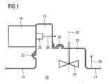
- FIG 1 shows a schematic sectional view of a feed box system according to a preferred embodiment of the present invention.
- the feed box system is arranged within a microwave oven.
- the feed box system includes a primary feed box 10 and a secondary feed box 12.
- the primary feed box 10 and the secondary feed box 12 are arranged one upon the other at a top wall 14 of an oven cavity 16.
- the primary feed box 10 and the secondary feed box 12 are substantially formed as cuboids.
- the secondary feed box 12 is arranged directly above an oven cavity 16.
- the base area of the secondary feed box 12 may be rectangular, circular or square.
- the primary feed box 10 is arranged directly above the secondary feed box 12.
- the width of the primary feed box 10 is smaller than the width of the secondary feed box 12.
- the circumference of the primary feed box 10 is smaller than the circumference of the secondary feed box 12.
- the feed box system is arranged on a top wall 14 of the oven cavity 16.
- the feed box system may be arranged at a side wall of the oven cavity 16.
- the secondary feed box 12 is formed out of the top wall 14 or side wall of the oven cavity 16, respectively, by an embossing or by a deep-drawing.
- the primary feed box 10 is fixed to the secondary feed box 12 and covers a recess of said secondary feed box 12.
- the primary feed box 10 is welded, screwed, clinched or riveted to the secondary feed box 12.
- the overlapping portions 22 of the primary feed box 10 and the secondary feed box 12 comprise multiple grooves extending along the circumference of the recess in the secondary feed box 12.
- the overlapping portions 22 of the primary feed box 10 and of the secondary feed box 12 have an S-shaped or meander-shaped cross-section.
- the overlapping portions 22 of the primary feed box 10 and of the secondary feed box 12 are complementary to each other, so that said overlapping portions form a wave labyrinth 22.
- Said wave labyrinth 22 encloses the common portion of the primary feed box 10 and the secondary feed box 12 completely or at least partially.
- the top wall 14 of the oven cavity 14 as well as the secondary feed box 12 is coated.
- the primary feed box 10 is fixed to the secondary feed box 12 after the enamel process.
- the primary feed box 10 is not coated by the enamel process.
- further walls of the oven cavity 16 may be enamelled.
- each wall of the oven cavity 14 and the secondary feed box 12 may be coated by the enamel process.
- a magnetron 18 is attached at the outer side of the primary feed box 10.
- An antenna 20 of the magnetron 18 extends into the interior of the primary feed box 10.
- the direction 26 of the antenna 20 extends orthogonal to a normal vector 28 of the top wall 14 of the oven cavity 16.
- the direction 26 of the antenna 20 of the inventive feed box system extends along another axis as the normal vector 28 of the cavity wall 14, at which said feed box system is arranged.
- stirrer 24 Within the secondary feed box 12 a stirrer 24 is arranged.
- the stirrer 24 is rotatable around a vertical rotation axis 30.
- An axle 32 of the stirrer 24 penetrates a top wall of the secondary feed box 12.
- the stirrer 24 is arranged within the secondary feed box 12.
- the stirrer 24 can extend at least partially into the interior of the oven cavity 16.
- the microwave oven with the feed box system according to the present invention requires less material as in the prior art due to the embossing or deep-drawing the secondary feed box 12 out of the oven cavity 16.
- a wave-tight connection between the primary feed box 10 and the secondary feed box 12 can be easily realized.
- the connection between the primary feed box 10 and the secondary feed box 12 needs only a few screws or bolts.
- the present invention allows a low cost production of the microwave oven with the feed box system.
- connection between the primary feed box 10 and the secondary feed box 12 allows a good electrical contact between the wave source and the feed box system.
- the embossing and/or deep-drawing of the secondary feed box 12 out of the oven cavity 16 allow an increased stiffness of the oven cavity 16.
Landscapes
- Physics & Mathematics (AREA)
- Electromagnetism (AREA)
- Engineering & Computer Science (AREA)
- Power Engineering (AREA)
- Electric Ovens (AREA)
Abstract
Description
- The present invention relates to a microwave oven with a feed box system according to claim 1.
- Microwave ovens are efficient cooking devices for heating food and beverages. However, the strong electromagnetic fields used for the microwave heating are a potential threat to the health of the operator. A special attention has to be paid in order to minimize any leakage of such electromagnetic waves.
- One of the critical parts within the microwave ovens is the connection between the wave source and the oven cavity. Very high power densities of the electromagnetic field occur in this area. Thus, a wave-tight system for the connection between the wave source and the oven cavity is required. For example, a magnetron can be used as the wave source.
- In known microwave ovens the connection between the magnetron and the oven cavity comprises three functional units. The first functional unit is a feed box acting as a wave channel between the magnetron and the oven cavity. The second functional unit is an interface portion for tightly mounting the magnetron to the feed box. The third functional unit is the fixation of the feed box to the oven cavity.
- The connection of the magnetron to the feed box is unproblematic with respect to microwave leakage. Also the setup of the feed box causes no difficulties related to microwave leakage. The critical point is the fixation of the feed box onto the oven cavity, since the connection between two separate components may create gaps through which microwaves can emanate into the surrounding area. For example, said gaps are caused by mechanical tolerances or by a limited planarity.
- The
US 5,825,000 describes a microwave oven with a feed box fixed directly at the oven cavity. The feed box comprises a wider portion and a smaller portion. A magnetron is fixed at the wider portion. - In the
DE 31 47 044 C2 a microwave oven with a feed box under the bottom wall of the oven cavity is disclosed. The feed box extends substantially under the whole bottom wall. Under the feed box a magnetron is arranged. Within said feed box there are a stirrer and an antenna of said magnetron. - The
US 3,939,320 discloses a microwave oven with a feed box above the oven cavity. A magnetron is arranged in the outer portion of the microwave oven. Between the feed box and the magnetron is a microwave channel. - In the above microwave ovens there are a lot of potential gaps between the feed box and the oven cavity or between the fed box and the microwave channel, respectively, so that microwave energy can emanate through those gaps.
- It is the object of the present invention to provide a microwave oven with an improved closeness between the wave source and the oven cavity.
This object is achieved by the microwave oven according to claim 1. - According to the present invention the microwave oven comprises a feed box system, wherein:
- the feed box system includes a primary feed box and a secondary feed box,
- the primary feed box and the secondary feed box are arranged one upon the other at a cavity wall of an oven cavity,
- the circumference of the primary feed box is smaller than the circumference of the secondary feed box,
- the secondary feed box and at least that cavity wall, at which the feed box system is arranged, form a single-piece part,
- the primary feed box is fixed to the secondary feed box and covers a recess of said secondary feed box,
- a microwave source is arranged at the primary feed box;
- an antenna of the microwave source extends into the interior of the primary feed box, and
- the axis of the antenna extends along another direction as a normal vector of the cavity wall, at which the feed box system is arranged.
- The core of the present invention is the feed box system with two separate feed boxes, wherein one feed box forms a single-piece part with the cavity wall, on the one hand and the direction of the antenna with respect to the normal vector of the cavity wall on the other hand. The number of potential gaps is reduced. The secondary feed box and the cavity wall form a single-piece part, so that there cannot be any potential gap between them. The primary feed box cover the recess of the secondary feed box, so that the probability of potential gaps between the primary and secondary feed box is reduced. The direction of the antenna impacts the streamlines of the electric and magnetic fields of the microwave with respect to the cavity wall.
- According to the preferred embodiment of the present invention the axis of the antenna extends orthogonal to the normal vector of that cavity wall, at which the feed box system is arranged. This constellation of the antenna restricts the directions of the streamlines of the electric and magnetic fields and supports the closeness of the oven cavity.
- Preferably, overlapping portions of the primary feed box and the secondary feed box are formed complementary to each other, so that the overlapping portions form a wave labyrinth. The wave labyrinth contributes to the closeness of the oven cavity.
- For example, the overlapping portions of the primary feed box and/or of the secondary feed box have an S-shaped or meander-shaped cross-section.
- According to the preferred embodiment of the present invention the secondary feed box is formed out of that cavity wall, at which the feed box system is arranged, by embossing and/or deep-drawing. The embossing and/or deep-drawing allow an efficient production of the microwave oven with the feed box system.
- Additionally, the secondary feed box may be formed out of the oven cavity by embossing and/or deep-drawing. This is an efficient method for the production of the oven cavity with the secondary feed box.
- Further, the secondary feed box and at least that cavity wall, at which the feed box system is arranged, may be enamelled. Since the primary feed box is fixed afterwards, the primary feed box remains un-enamelled. This allows a very good electrical contact between the wave source and the primary feed box.
- Additionally, the secondary feed box and the oven cavity may be enamelled.
- For example, the primary feed box is welded, screwed, clinched and/or riveted to the secondary feed box.
- According to the preferred embodiment of the present invention the primary feed box covers a recess of the secondary feed box. Thereby, the wave labyrinth may enclose the recess completely or at least partially.
- For example, the microwave oven may comprise at least one stirrer arranged at least partially within the secondary feed box. However, the stirrer may extend partially into the oven cavity.
- According to the preferred embodiment of the present invention the microwave source is a magnetron.
- The invention will be explained in more detail below by means of an exemplary embodiment. Reference is thereby made to the drawing, wherein
- FIG 1
- shows a schematic sectional view of a feed box system within a microwave oven according to a preferred embodiment of the present invention.
-
FIG 1 shows a schematic sectional view of a feed box system according to a preferred embodiment of the present invention. The feed box system is arranged within a microwave oven. The feed box system includes aprimary feed box 10 and asecondary feed box 12. Theprimary feed box 10 and thesecondary feed box 12 are arranged one upon the other at atop wall 14 of anoven cavity 16. - In this embodiment the
primary feed box 10 and thesecondary feed box 12 are substantially formed as cuboids. Thesecondary feed box 12 is arranged directly above anoven cavity 16. The base area of thesecondary feed box 12 may be rectangular, circular or square. Theprimary feed box 10 is arranged directly above thesecondary feed box 12. The width of theprimary feed box 10 is smaller than the width of thesecondary feed box 12. Also the circumference of theprimary feed box 10 is smaller than the circumference of thesecondary feed box 12. - In this example the feed box system is arranged on a
top wall 14 of theoven cavity 16. Alternatively, the feed box system may be arranged at a side wall of theoven cavity 16. Thesecondary feed box 12 and thetop wall 14 or side wall of theoven cavity 16, respectively, form a single-piece part. For example, thesecondary feed box 12 is formed out of thetop wall 14 or side wall of theoven cavity 16, respectively, by an embossing or by a deep-drawing. - The
primary feed box 10 is fixed to thesecondary feed box 12 and covers a recess of saidsecondary feed box 12. For example, theprimary feed box 10 is welded, screwed, clinched or riveted to thesecondary feed box 12. The overlappingportions 22 of theprimary feed box 10 and thesecondary feed box 12 comprise multiple grooves extending along the circumference of the recess in thesecondary feed box 12. Thus, the overlappingportions 22 of theprimary feed box 10 and of thesecondary feed box 12 have an S-shaped or meander-shaped cross-section. - Further, the overlapping
portions 22 of theprimary feed box 10 and of thesecondary feed box 12 are complementary to each other, so that said overlapping portions form awave labyrinth 22. Saidwave labyrinth 22 encloses the common portion of theprimary feed box 10 and thesecondary feed box 12 completely or at least partially. - By an enamel process the
top wall 14 of theoven cavity 14 as well as thesecondary feed box 12 is coated. Theprimary feed box 10 is fixed to thesecondary feed box 12 after the enamel process. Thus, theprimary feed box 10 is not coated by the enamel process. Additionally, further walls of theoven cavity 16 may be enamelled. For example, each wall of theoven cavity 14 and thesecondary feed box 12 may be coated by the enamel process. - A
magnetron 18 is attached at the outer side of theprimary feed box 10. Anantenna 20 of themagnetron 18 extends into the interior of theprimary feed box 10. In this example, thedirection 26 of theantenna 20 extends orthogonal to anormal vector 28 of thetop wall 14 of theoven cavity 16. In general, thedirection 26 of theantenna 20 of the inventive feed box system extends along another axis as thenormal vector 28 of thecavity wall 14, at which said feed box system is arranged. - Within the secondary feed box 12 a
stirrer 24 is arranged. Thestirrer 24 is rotatable around avertical rotation axis 30. An axle 32 of thestirrer 24 penetrates a top wall of thesecondary feed box 12. In this example, thestirrer 24 is arranged within thesecondary feed box 12. Alternatively, thestirrer 24 can extend at least partially into the interior of theoven cavity 16. - The microwave oven with the feed box system according to the present invention requires less material as in the prior art due to the embossing or deep-drawing the
secondary feed box 12 out of theoven cavity 16. A wave-tight connection between theprimary feed box 10 and thesecondary feed box 12 can be easily realized. The connection between theprimary feed box 10 and thesecondary feed box 12 needs only a few screws or bolts. Thus, the present invention allows a low cost production of the microwave oven with the feed box system. - The connection between the
primary feed box 10 and thesecondary feed box 12 allows a good electrical contact between the wave source and the feed box system. The embossing and/or deep-drawing of thesecondary feed box 12 out of theoven cavity 16 allow an increased stiffness of theoven cavity 16. -
10 primary feed box 12 secondary feed box 14 top wall, cavity wall 16 oven cavity 18 magnetron 20 antenna 22 overlapping portions, wave labyrinth 24 stirrer 26 direction of the antenna 28 normal vector of the wall 30 vertical rotation axis
Claims (14)
- A microwave oven with a feed box system, wherein:- the feed box system includes a primary feed box (10) and a secondary feed box (12),- the primary feed box (10) and the secondary feed box (12) are arranged one upon the other at a cavity wall (14) of an oven cavity (16),- the circumference of the primary feed box (10) is smaller than the circumference of the secondary feed box (12),- the secondary feed box (12) and at least that cavity wall (14), at which the feed box system is arranged, form a single-piece part,- the primary feed box (10) is fixed to the secondary feed box (12) and covers a recess of said secondary feed box (12),- a microwave source (18) is arranged at the primary feed box (10) ;- an antenna (20) of the microwave source (18) extends into the interior of the primary feed box (10), and- the axis of the antenna (20) extends along another direction as a normal vector of the cavity wall (14), at which the feed box system is arranged.
- The microwave oven according to claim 1,
characterized in that
the axis of the antenna (20) extends orthogonal to the normal vector of the cavity wall (14), at which the feed box system is arranged. - The microwave oven according to claim 1 or 2,
characterized in that
overlapping portions (22) of the primary feed box (10) and the secondary feed box (12) are formed complementary to each other, so that the overlapping portions (22) form a wave labyrinth. - The microwave oven according to any one of the preceding claims,
characterized in that
the overlapping portions (22) of the primary feed box (10) and/or of the secondary feed box (12) have an S-shaped or meander-shaped cross-section. - The microwave oven according to any one of the preceding claims,
characterized in that
the secondary feed box (12) is formed out of that cavity wall (14), at which the feed box system is arranged, by embossing and/or deep-drawing. - The microwave oven according to any one of the claims 1 to 4,
characterized in that
the secondary feed box (12) is formed out of the oven cavity (16) by embossing and/or deep-drawing. - The microwave oven according to any one of the preceding claims,
characterized in that
the secondary feed box (12) and at least that cavity wall (14), at which the feed box system is arranged, are enamelled. - The microwave oven according to any one of the preceding claims,
characterized in that
the secondary feed box (12) and the oven cavity (16) are enamelled. - The microwave oven according to any one of the preceding claims,
characterized in that
the primary feed box (10) is welded, screwed, clinched and/or riveted to the secondary feed box (12). - The microwave oven according to any one of the preceding claims,
characterized in that
the primary feed box (10) covers a recess of the secondary feed box (12). - The microwave oven according to claim 10 as far as referred back to claim 3,
characterized in that
the wave labyrinth (22) encloses the recess completely or at least partially. - The microwave oven according to any one of the preceding claims,
characterized in that
the microwave oven comprises at least one stirrer (24) arranged at least partially within the secondary feed box (12). - The microwave oven according to claim 12,
characterized in that
the stirrer (24) extends partially into the oven cavity (16). - The microwave oven according to any one of the preceding claims,
characterized in that
the microwave source is a magnetron (18).
Priority Applications (1)
| Application Number | Priority Date | Filing Date | Title |
|---|---|---|---|
| EP09006048.4A EP2265090B1 (en) | 2009-05-02 | 2009-05-02 | A microwave oven with a feed box system |
Applications Claiming Priority (1)
| Application Number | Priority Date | Filing Date | Title |
|---|---|---|---|
| EP09006048.4A EP2265090B1 (en) | 2009-05-02 | 2009-05-02 | A microwave oven with a feed box system |
Publications (2)
| Publication Number | Publication Date |
|---|---|
| EP2265090A1 true EP2265090A1 (en) | 2010-12-22 |
| EP2265090B1 EP2265090B1 (en) | 2017-12-20 |
Family
ID=41168701
Family Applications (1)
| Application Number | Title | Priority Date | Filing Date |
|---|---|---|---|
| EP09006048.4A Not-in-force EP2265090B1 (en) | 2009-05-02 | 2009-05-02 | A microwave oven with a feed box system |
Country Status (1)
| Country | Link |
|---|---|
| EP (1) | EP2265090B1 (en) |
Cited By (1)
| Publication number | Priority date | Publication date | Assignee | Title |
|---|---|---|---|---|
| EP2784395A1 (en) * | 2013-03-25 | 2014-10-01 | Electrolux Appliances Aktiebolag | Oven cavity for a cooking oven |
Citations (14)
| Publication number | Priority date | Publication date | Assignee | Title |
|---|---|---|---|---|
| US3939320A (en) | 1974-04-12 | 1976-02-17 | Micro-Tronics, Inc. | Beam stirrer |
| US4159406A (en) * | 1977-05-31 | 1979-06-26 | Whirlpool Corporation | Waveguide assembly for microwave oven |
| GB2107160A (en) * | 1981-06-16 | 1983-04-20 | Sharp Kk | Microwave ovens |
| JPS6172936A (en) * | 1984-09-14 | 1986-04-15 | Matsushita Electric Ind Co Ltd | microwave oven |
| EP0186104A2 (en) * | 1984-12-20 | 1986-07-02 | Matsushita Electric Industrial Co., Ltd. | Microwave heating oven |
| US4701586A (en) * | 1986-05-30 | 1987-10-20 | Litton Systems, Inc. | Magnetron mounting system |
| DE3147044C2 (en) | 1981-11-27 | 1987-12-17 | Licentia Patent-Verwaltungs-Gmbh, 6000 Frankfurt, De | |
| US4808784A (en) * | 1987-03-14 | 1989-02-28 | Sam Sung Electronic Co., Ltd. | High frequency dispersing device in a microwave oven |
| GB2267634A (en) * | 1992-06-01 | 1993-12-08 | Matsushita Electric Industrial Co Ltd | Microwave oven with electromagnetic wave distributor |
| US5825000A (en) | 1996-08-31 | 1998-10-20 | Daewoo Electronics Co., Ltd. | Wave guide system of a microwave oven |
| GB2331687A (en) * | 1997-11-22 | 1999-05-26 | Samsung Electronics Co Ltd | Microwave oven with drainage holes |
| US6246039B1 (en) * | 1999-02-19 | 2001-06-12 | Sanyo Electric Co., Ltd. | High frequency heating apparatus having a wave guide introducing microwaves into heating chamber |
| JP2005011620A (en) * | 2003-06-18 | 2005-01-13 | Matsushita Electric Ind Co Ltd | microwave |
| EP2037180A1 (en) * | 2007-09-14 | 2009-03-18 | Teka Portugal, S.A. | Built-in kitchen appliance |
-
2009
- 2009-05-02 EP EP09006048.4A patent/EP2265090B1/en not_active Not-in-force
Patent Citations (14)
| Publication number | Priority date | Publication date | Assignee | Title |
|---|---|---|---|---|
| US3939320A (en) | 1974-04-12 | 1976-02-17 | Micro-Tronics, Inc. | Beam stirrer |
| US4159406A (en) * | 1977-05-31 | 1979-06-26 | Whirlpool Corporation | Waveguide assembly for microwave oven |
| GB2107160A (en) * | 1981-06-16 | 1983-04-20 | Sharp Kk | Microwave ovens |
| DE3147044C2 (en) | 1981-11-27 | 1987-12-17 | Licentia Patent-Verwaltungs-Gmbh, 6000 Frankfurt, De | |
| JPS6172936A (en) * | 1984-09-14 | 1986-04-15 | Matsushita Electric Ind Co Ltd | microwave oven |
| EP0186104A2 (en) * | 1984-12-20 | 1986-07-02 | Matsushita Electric Industrial Co., Ltd. | Microwave heating oven |
| US4701586A (en) * | 1986-05-30 | 1987-10-20 | Litton Systems, Inc. | Magnetron mounting system |
| US4808784A (en) * | 1987-03-14 | 1989-02-28 | Sam Sung Electronic Co., Ltd. | High frequency dispersing device in a microwave oven |
| GB2267634A (en) * | 1992-06-01 | 1993-12-08 | Matsushita Electric Industrial Co Ltd | Microwave oven with electromagnetic wave distributor |
| US5825000A (en) | 1996-08-31 | 1998-10-20 | Daewoo Electronics Co., Ltd. | Wave guide system of a microwave oven |
| GB2331687A (en) * | 1997-11-22 | 1999-05-26 | Samsung Electronics Co Ltd | Microwave oven with drainage holes |
| US6246039B1 (en) * | 1999-02-19 | 2001-06-12 | Sanyo Electric Co., Ltd. | High frequency heating apparatus having a wave guide introducing microwaves into heating chamber |
| JP2005011620A (en) * | 2003-06-18 | 2005-01-13 | Matsushita Electric Ind Co Ltd | microwave |
| EP2037180A1 (en) * | 2007-09-14 | 2009-03-18 | Teka Portugal, S.A. | Built-in kitchen appliance |
Cited By (1)
| Publication number | Priority date | Publication date | Assignee | Title |
|---|---|---|---|---|
| EP2784395A1 (en) * | 2013-03-25 | 2014-10-01 | Electrolux Appliances Aktiebolag | Oven cavity for a cooking oven |
Also Published As
| Publication number | Publication date |
|---|---|
| EP2265090B1 (en) | 2017-12-20 |
Similar Documents
| Publication | Publication Date | Title |
|---|---|---|
| EP3096337B1 (en) | Dual coil wireless power transmitter | |
| US9859718B2 (en) | Power supply unit, power receiving unit, and power supply system | |
| EP3139702B1 (en) | Induction coil assembly for an induction cooking hob | |
| EP2737606B1 (en) | Wireless power transmitter and wireless power receiver | |
| US20170156180A1 (en) | Induction heating arrangement and induction hob | |
| JP6520567B2 (en) | Power supply device | |
| US20130062311A1 (en) | Inductively coupled plasma processing apparatus and method for processing substrate with the same | |
| US20030076212A1 (en) | Fault current limiter | |
| EP3384731B1 (en) | Microwave oven | |
| EP1426984A1 (en) | Transformer assembly for microwave oven, method for manufacturing the same, and microwave oven having the same | |
| EP2265090B1 (en) | A microwave oven with a feed box system | |
| EP2257121A1 (en) | A microwave oven with at least one wave choke system | |
| EP2704547A2 (en) | Shielding Structure for Power Conversion System and Method Thereof | |
| US10554078B2 (en) | Method and apparatus for coil integration for uniform wireless charging | |
| EP0644563B1 (en) | Capacitor for magnetron of microwave oven | |
| US9698606B2 (en) | Wireless power transmission antenna apparatus | |
| US5739736A (en) | Mounting arrangement for a high-voltage transformer of a microwave oven | |
| CN210725396U (en) | Low-radiation electromagnetic heating equipment | |
| US5455405A (en) | Noise shielding apparatus for magnetron of microwave oven | |
| EP2991446A1 (en) | Induction heating arrangement and induction hob | |
| CN207082916U (en) | A kind of motor stator | |
| CN208113012U (en) | Coil panel component and electromagnetic heating cooking utensil | |
| CN222464291U (en) | Connection structure of magnetism isolating high-voltage wire seat and mixing box | |
| CN216087059U (en) | Electromagnetic heating assembly and electromagnetic heating cooking utensil | |
| CN220441182U (en) | Housing component for housing of electromagnetic shielding electronic component and housing |
Legal Events
| Date | Code | Title | Description |
|---|---|---|---|
| PUAI | Public reference made under article 153(3) epc to a published international application that has entered the european phase |
Free format text: ORIGINAL CODE: 0009012 |
|
| 17P | Request for examination filed |
Effective date: 20100112 |
|
| AK | Designated contracting states |
Kind code of ref document: A1 Designated state(s): AT BE BG CH CY CZ DE DK EE ES FI FR GB GR HR HU IE IS IT LI LT LU LV MC MK MT NL NO PL PT RO SE SI SK TR |
|
| AX | Request for extension of the european patent |
Extension state: AL BA RS |
|
| RAP1 | Party data changed (applicant data changed or rights of an application transferred) |
Owner name: ELECTROLUX HOME PRODUCTS CORPORATION N.V. |
|
| RAP1 | Party data changed (applicant data changed or rights of an application transferred) |
Owner name: ELECTROLUX HOME PRODUCTS CORPORATION N.V. |
|
| REG | Reference to a national code |
Ref country code: DE Ref legal event code: R079 Ref document number: 602009049940 Country of ref document: DE Free format text: PREVIOUS MAIN CLASS: H05B0006700000 Ipc: H05B0006740000 |
|
| GRAP | Despatch of communication of intention to grant a patent |
Free format text: ORIGINAL CODE: EPIDOSNIGR1 |
|
| RIC1 | Information provided on ipc code assigned before grant |
Ipc: H05B 6/76 20060101ALI20170720BHEP Ipc: H05B 6/70 20060101ALI20170720BHEP Ipc: H05B 6/74 20060101AFI20170720BHEP |
|
| INTG | Intention to grant announced |
Effective date: 20170808 |
|
| GRAS | Grant fee paid |
Free format text: ORIGINAL CODE: EPIDOSNIGR3 |
|
| GRAA | (expected) grant |
Free format text: ORIGINAL CODE: 0009210 |
|
| AK | Designated contracting states |
Kind code of ref document: B1 Designated state(s): AT BE BG CH CY CZ DE DK EE ES FI FR GB GR HR HU IE IS IT LI LT LU LV MC MK MT NL NO PL PT RO SE SI SK TR |
|
| REG | Reference to a national code |
Ref country code: GB Ref legal event code: FG4D |
|
| REG | Reference to a national code |
Ref country code: CH Ref legal event code: EP |
|
| REG | Reference to a national code |
Ref country code: IE Ref legal event code: FG4D |
|
| REG | Reference to a national code |
Ref country code: AT Ref legal event code: REF Ref document number: 957474 Country of ref document: AT Kind code of ref document: T Effective date: 20180115 |
|
| REG | Reference to a national code |
Ref country code: DE Ref legal event code: R096 Ref document number: 602009049940 Country of ref document: DE |
|
| REG | Reference to a national code |
Ref country code: NL Ref legal event code: MP Effective date: 20171220 |
|
| PG25 | Lapsed in a contracting state [announced via postgrant information from national office to epo] |
Ref country code: LT Free format text: LAPSE BECAUSE OF FAILURE TO SUBMIT A TRANSLATION OF THE DESCRIPTION OR TO PAY THE FEE WITHIN THE PRESCRIBED TIME-LIMIT Effective date: 20171220 Ref country code: SE Free format text: LAPSE BECAUSE OF FAILURE TO SUBMIT A TRANSLATION OF THE DESCRIPTION OR TO PAY THE FEE WITHIN THE PRESCRIBED TIME-LIMIT Effective date: 20171220 Ref country code: NO Free format text: LAPSE BECAUSE OF FAILURE TO SUBMIT A TRANSLATION OF THE DESCRIPTION OR TO PAY THE FEE WITHIN THE PRESCRIBED TIME-LIMIT Effective date: 20180320 Ref country code: FI Free format text: LAPSE BECAUSE OF FAILURE TO SUBMIT A TRANSLATION OF THE DESCRIPTION OR TO PAY THE FEE WITHIN THE PRESCRIBED TIME-LIMIT Effective date: 20171220 |
|
| REG | Reference to a national code |
Ref country code: LT Ref legal event code: MG4D |
|
| REG | Reference to a national code |
Ref country code: AT Ref legal event code: MK05 Ref document number: 957474 Country of ref document: AT Kind code of ref document: T Effective date: 20171220 |
|
| PG25 | Lapsed in a contracting state [announced via postgrant information from national office to epo] |
Ref country code: GR Free format text: LAPSE BECAUSE OF FAILURE TO SUBMIT A TRANSLATION OF THE DESCRIPTION OR TO PAY THE FEE WITHIN THE PRESCRIBED TIME-LIMIT Effective date: 20180321 Ref country code: BG Free format text: LAPSE BECAUSE OF FAILURE TO SUBMIT A TRANSLATION OF THE DESCRIPTION OR TO PAY THE FEE WITHIN THE PRESCRIBED TIME-LIMIT Effective date: 20180320 Ref country code: LV Free format text: LAPSE BECAUSE OF FAILURE TO SUBMIT A TRANSLATION OF THE DESCRIPTION OR TO PAY THE FEE WITHIN THE PRESCRIBED TIME-LIMIT Effective date: 20171220 Ref country code: HR Free format text: LAPSE BECAUSE OF FAILURE TO SUBMIT A TRANSLATION OF THE DESCRIPTION OR TO PAY THE FEE WITHIN THE PRESCRIBED TIME-LIMIT Effective date: 20171220 |
|
| PG25 | Lapsed in a contracting state [announced via postgrant information from national office to epo] |
Ref country code: NL Free format text: LAPSE BECAUSE OF FAILURE TO SUBMIT A TRANSLATION OF THE DESCRIPTION OR TO PAY THE FEE WITHIN THE PRESCRIBED TIME-LIMIT Effective date: 20171220 |
|
| PG25 | Lapsed in a contracting state [announced via postgrant information from national office to epo] |
Ref country code: CZ Free format text: LAPSE BECAUSE OF FAILURE TO SUBMIT A TRANSLATION OF THE DESCRIPTION OR TO PAY THE FEE WITHIN THE PRESCRIBED TIME-LIMIT Effective date: 20171220 Ref country code: SK Free format text: LAPSE BECAUSE OF FAILURE TO SUBMIT A TRANSLATION OF THE DESCRIPTION OR TO PAY THE FEE WITHIN THE PRESCRIBED TIME-LIMIT Effective date: 20171220 Ref country code: CY Free format text: LAPSE BECAUSE OF FAILURE TO SUBMIT A TRANSLATION OF THE DESCRIPTION OR TO PAY THE FEE WITHIN THE PRESCRIBED TIME-LIMIT Effective date: 20171220 Ref country code: EE Free format text: LAPSE BECAUSE OF FAILURE TO SUBMIT A TRANSLATION OF THE DESCRIPTION OR TO PAY THE FEE WITHIN THE PRESCRIBED TIME-LIMIT Effective date: 20171220 Ref country code: ES Free format text: LAPSE BECAUSE OF FAILURE TO SUBMIT A TRANSLATION OF THE DESCRIPTION OR TO PAY THE FEE WITHIN THE PRESCRIBED TIME-LIMIT Effective date: 20171220 |
|
| PG25 | Lapsed in a contracting state [announced via postgrant information from national office to epo] |
Ref country code: RO Free format text: LAPSE BECAUSE OF FAILURE TO SUBMIT A TRANSLATION OF THE DESCRIPTION OR TO PAY THE FEE WITHIN THE PRESCRIBED TIME-LIMIT Effective date: 20171220 Ref country code: PL Free format text: LAPSE BECAUSE OF FAILURE TO SUBMIT A TRANSLATION OF THE DESCRIPTION OR TO PAY THE FEE WITHIN THE PRESCRIBED TIME-LIMIT Effective date: 20171220 Ref country code: AT Free format text: LAPSE BECAUSE OF FAILURE TO SUBMIT A TRANSLATION OF THE DESCRIPTION OR TO PAY THE FEE WITHIN THE PRESCRIBED TIME-LIMIT Effective date: 20171220 Ref country code: IS Free format text: LAPSE BECAUSE OF FAILURE TO SUBMIT A TRANSLATION OF THE DESCRIPTION OR TO PAY THE FEE WITHIN THE PRESCRIBED TIME-LIMIT Effective date: 20180420 |
|
| REG | Reference to a national code |
Ref country code: DE Ref legal event code: R097 Ref document number: 602009049940 Country of ref document: DE |
|
| PLBE | No opposition filed within time limit |
Free format text: ORIGINAL CODE: 0009261 |
|
| STAA | Information on the status of an ep patent application or granted ep patent |
Free format text: STATUS: NO OPPOSITION FILED WITHIN TIME LIMIT |
|
| 26N | No opposition filed |
Effective date: 20180921 |
|
| PG25 | Lapsed in a contracting state [announced via postgrant information from national office to epo] |
Ref country code: DK Free format text: LAPSE BECAUSE OF FAILURE TO SUBMIT A TRANSLATION OF THE DESCRIPTION OR TO PAY THE FEE WITHIN THE PRESCRIBED TIME-LIMIT Effective date: 20171220 |
|
| REG | Reference to a national code |
Ref country code: CH Ref legal event code: PL |
|
| GBPC | Gb: european patent ceased through non-payment of renewal fee |
Effective date: 20180502 |
|
| REG | Reference to a national code |
Ref country code: BE Ref legal event code: MM Effective date: 20180531 |
|
| PG25 | Lapsed in a contracting state [announced via postgrant information from national office to epo] |
Ref country code: MC Free format text: LAPSE BECAUSE OF FAILURE TO SUBMIT A TRANSLATION OF THE DESCRIPTION OR TO PAY THE FEE WITHIN THE PRESCRIBED TIME-LIMIT Effective date: 20171220 |
|
| REG | Reference to a national code |
Ref country code: IE Ref legal event code: MM4A |
|
| PG25 | Lapsed in a contracting state [announced via postgrant information from national office to epo] |
Ref country code: LI Free format text: LAPSE BECAUSE OF NON-PAYMENT OF DUE FEES Effective date: 20180531 Ref country code: CH Free format text: LAPSE BECAUSE OF NON-PAYMENT OF DUE FEES Effective date: 20180531 Ref country code: SI Free format text: LAPSE BECAUSE OF FAILURE TO SUBMIT A TRANSLATION OF THE DESCRIPTION OR TO PAY THE FEE WITHIN THE PRESCRIBED TIME-LIMIT Effective date: 20171220 |
|
| PG25 | Lapsed in a contracting state [announced via postgrant information from national office to epo] |
Ref country code: LU Free format text: LAPSE BECAUSE OF NON-PAYMENT OF DUE FEES Effective date: 20180502 |
|
| PG25 | Lapsed in a contracting state [announced via postgrant information from national office to epo] |
Ref country code: IE Free format text: LAPSE BECAUSE OF NON-PAYMENT OF DUE FEES Effective date: 20180502 Ref country code: GB Free format text: LAPSE BECAUSE OF NON-PAYMENT OF DUE FEES Effective date: 20180502 Ref country code: FR Free format text: LAPSE BECAUSE OF NON-PAYMENT OF DUE FEES Effective date: 20180531 |
|
| PG25 | Lapsed in a contracting state [announced via postgrant information from national office to epo] |
Ref country code: BE Free format text: LAPSE BECAUSE OF NON-PAYMENT OF DUE FEES Effective date: 20180531 |
|
| PG25 | Lapsed in a contracting state [announced via postgrant information from national office to epo] |
Ref country code: MT Free format text: LAPSE BECAUSE OF NON-PAYMENT OF DUE FEES Effective date: 20180502 |
|
| PG25 | Lapsed in a contracting state [announced via postgrant information from national office to epo] |
Ref country code: TR Free format text: LAPSE BECAUSE OF FAILURE TO SUBMIT A TRANSLATION OF THE DESCRIPTION OR TO PAY THE FEE WITHIN THE PRESCRIBED TIME-LIMIT Effective date: 20171220 |
|
| PG25 | Lapsed in a contracting state [announced via postgrant information from national office to epo] |
Ref country code: HU Free format text: LAPSE BECAUSE OF FAILURE TO SUBMIT A TRANSLATION OF THE DESCRIPTION OR TO PAY THE FEE WITHIN THE PRESCRIBED TIME-LIMIT; INVALID AB INITIO Effective date: 20090502 Ref country code: PT Free format text: LAPSE BECAUSE OF FAILURE TO SUBMIT A TRANSLATION OF THE DESCRIPTION OR TO PAY THE FEE WITHIN THE PRESCRIBED TIME-LIMIT Effective date: 20171220 |
|
| PG25 | Lapsed in a contracting state [announced via postgrant information from national office to epo] |
Ref country code: MK Free format text: LAPSE BECAUSE OF NON-PAYMENT OF DUE FEES Effective date: 20171220 |
|
| PGFP | Annual fee paid to national office [announced via postgrant information from national office to epo] |
Ref country code: IT Payment date: 20220524 Year of fee payment: 14 Ref country code: DE Payment date: 20220519 Year of fee payment: 14 |
|
| REG | Reference to a national code |
Ref country code: DE Ref legal event code: R119 Ref document number: 602009049940 Country of ref document: DE |
|
| PG25 | Lapsed in a contracting state [announced via postgrant information from national office to epo] |
Ref country code: IT Free format text: LAPSE BECAUSE OF NON-PAYMENT OF DUE FEES Effective date: 20230502 Ref country code: DE Free format text: LAPSE BECAUSE OF NON-PAYMENT OF DUE FEES Effective date: 20231201 |