EP2265033A2 - Stereoscopic display apparatus and control method of the same - Google Patents
Stereoscopic display apparatus and control method of the same Download PDFInfo
- Publication number
- EP2265033A2 EP2265033A2 EP10154024A EP10154024A EP2265033A2 EP 2265033 A2 EP2265033 A2 EP 2265033A2 EP 10154024 A EP10154024 A EP 10154024A EP 10154024 A EP10154024 A EP 10154024A EP 2265033 A2 EP2265033 A2 EP 2265033A2
- Authority
- EP
- European Patent Office
- Prior art keywords
- light emitting
- eye
- shutter
- image
- organic light
- Prior art date
- Legal status (The legal status is an assumption and is not a legal conclusion. Google has not performed a legal analysis and makes no representation as to the accuracy of the status listed.)
- Granted
Links
Images


Classifications
-
- G—PHYSICS
- G09—EDUCATION; CRYPTOGRAPHY; DISPLAY; ADVERTISING; SEALS
- G09G—ARRANGEMENTS OR CIRCUITS FOR CONTROL OF INDICATING DEVICES USING STATIC MEANS TO PRESENT VARIABLE INFORMATION
- G09G3/00—Control arrangements or circuits, of interest only in connection with visual indicators other than cathode-ray tubes
- G09G3/20—Control arrangements or circuits, of interest only in connection with visual indicators other than cathode-ray tubes for presentation of an assembly of a number of characters, e.g. a page, by composing the assembly by combination of individual elements arranged in a matrix no fixed position being assigned to or needed to be assigned to the individual characters or partial characters
- G09G3/22—Control arrangements or circuits, of interest only in connection with visual indicators other than cathode-ray tubes for presentation of an assembly of a number of characters, e.g. a page, by composing the assembly by combination of individual elements arranged in a matrix no fixed position being assigned to or needed to be assigned to the individual characters or partial characters using controlled light sources
- G09G3/30—Control arrangements or circuits, of interest only in connection with visual indicators other than cathode-ray tubes for presentation of an assembly of a number of characters, e.g. a page, by composing the assembly by combination of individual elements arranged in a matrix no fixed position being assigned to or needed to be assigned to the individual characters or partial characters using controlled light sources using electroluminescent panels
- G09G3/32—Control arrangements or circuits, of interest only in connection with visual indicators other than cathode-ray tubes for presentation of an assembly of a number of characters, e.g. a page, by composing the assembly by combination of individual elements arranged in a matrix no fixed position being assigned to or needed to be assigned to the individual characters or partial characters using controlled light sources using electroluminescent panels semiconductive, e.g. using light-emitting diodes [LED]
- G09G3/3208—Control arrangements or circuits, of interest only in connection with visual indicators other than cathode-ray tubes for presentation of an assembly of a number of characters, e.g. a page, by composing the assembly by combination of individual elements arranged in a matrix no fixed position being assigned to or needed to be assigned to the individual characters or partial characters using controlled light sources using electroluminescent panels semiconductive, e.g. using light-emitting diodes [LED] organic, e.g. using organic light-emitting diodes [OLED]
- G09G3/3225—Control arrangements or circuits, of interest only in connection with visual indicators other than cathode-ray tubes for presentation of an assembly of a number of characters, e.g. a page, by composing the assembly by combination of individual elements arranged in a matrix no fixed position being assigned to or needed to be assigned to the individual characters or partial characters using controlled light sources using electroluminescent panels semiconductive, e.g. using light-emitting diodes [LED] organic, e.g. using organic light-emitting diodes [OLED] using an active matrix
- G09G3/3233—Control arrangements or circuits, of interest only in connection with visual indicators other than cathode-ray tubes for presentation of an assembly of a number of characters, e.g. a page, by composing the assembly by combination of individual elements arranged in a matrix no fixed position being assigned to or needed to be assigned to the individual characters or partial characters using controlled light sources using electroluminescent panels semiconductive, e.g. using light-emitting diodes [LED] organic, e.g. using organic light-emitting diodes [OLED] using an active matrix with pixel circuitry controlling the current through the light-emitting element
-
- G—PHYSICS
- G09—EDUCATION; CRYPTOGRAPHY; DISPLAY; ADVERTISING; SEALS
- G09G—ARRANGEMENTS OR CIRCUITS FOR CONTROL OF INDICATING DEVICES USING STATIC MEANS TO PRESENT VARIABLE INFORMATION
- G09G3/00—Control arrangements or circuits, of interest only in connection with visual indicators other than cathode-ray tubes
- G09G3/001—Control arrangements or circuits, of interest only in connection with visual indicators other than cathode-ray tubes using specific devices not provided for in groups G09G3/02 - G09G3/36, e.g. using an intermediate record carrier such as a film slide; Projection systems; Display of non-alphanumerical information, solely or in combination with alphanumerical information, e.g. digital display on projected diapositive as background
- G09G3/003—Control arrangements or circuits, of interest only in connection with visual indicators other than cathode-ray tubes using specific devices not provided for in groups G09G3/02 - G09G3/36, e.g. using an intermediate record carrier such as a film slide; Projection systems; Display of non-alphanumerical information, solely or in combination with alphanumerical information, e.g. digital display on projected diapositive as background to produce spatial visual effects
-
- G—PHYSICS
- G09—EDUCATION; CRYPTOGRAPHY; DISPLAY; ADVERTISING; SEALS
- G09G—ARRANGEMENTS OR CIRCUITS FOR CONTROL OF INDICATING DEVICES USING STATIC MEANS TO PRESENT VARIABLE INFORMATION
- G09G3/00—Control arrangements or circuits, of interest only in connection with visual indicators other than cathode-ray tubes
- G09G3/20—Control arrangements or circuits, of interest only in connection with visual indicators other than cathode-ray tubes for presentation of an assembly of a number of characters, e.g. a page, by composing the assembly by combination of individual elements arranged in a matrix no fixed position being assigned to or needed to be assigned to the individual characters or partial characters
- G09G3/22—Control arrangements or circuits, of interest only in connection with visual indicators other than cathode-ray tubes for presentation of an assembly of a number of characters, e.g. a page, by composing the assembly by combination of individual elements arranged in a matrix no fixed position being assigned to or needed to be assigned to the individual characters or partial characters using controlled light sources
- G09G3/30—Control arrangements or circuits, of interest only in connection with visual indicators other than cathode-ray tubes for presentation of an assembly of a number of characters, e.g. a page, by composing the assembly by combination of individual elements arranged in a matrix no fixed position being assigned to or needed to be assigned to the individual characters or partial characters using controlled light sources using electroluminescent panels
- G09G3/32—Control arrangements or circuits, of interest only in connection with visual indicators other than cathode-ray tubes for presentation of an assembly of a number of characters, e.g. a page, by composing the assembly by combination of individual elements arranged in a matrix no fixed position being assigned to or needed to be assigned to the individual characters or partial characters using controlled light sources using electroluminescent panels semiconductive, e.g. using light-emitting diodes [LED]
-
- H—ELECTRICITY
- H04—ELECTRIC COMMUNICATION TECHNIQUE
- H04N—PICTORIAL COMMUNICATION, e.g. TELEVISION
- H04N13/00—Stereoscopic video systems; Multi-view video systems; Details thereof
- H04N13/30—Image reproducers
- H04N13/332—Displays for viewing with the aid of special glasses or head-mounted displays [HMD]
- H04N13/341—Displays for viewing with the aid of special glasses or head-mounted displays [HMD] using temporal multiplexing
-
- H—ELECTRICITY
- H04—ELECTRIC COMMUNICATION TECHNIQUE
- H04N—PICTORIAL COMMUNICATION, e.g. TELEVISION
- H04N13/00—Stereoscopic video systems; Multi-view video systems; Details thereof
- H04N13/30—Image reproducers
- H04N13/398—Synchronisation thereof; Control thereof
Definitions
- Apparatuses and methods consistent with the inventive concept relate to a display apparatus and a control method of the same, and more particularly, to displaying a three-dimensional (3D) image and a control method of the same.
- a display apparatus processes various kinds of digital and/or analog video signals and displays an image.
- a user can view a 3D image based on a 3D video signal on a monitor, television (TV), or the like.
- the 3D video signal is divided into contents for a user's left eye and contents for a right eye, and the divided images are displayed for the left and right eyes, respectively.
- the shutter glasses are turned on and off to alternately show left and right images so that a user can view the 3D image using the divided images corresponding to the left and right eyes.
- an opening period of the shutter glasses may needs to be adjusted to prevent crosstalk generated when the left-eye image and the right-eye image are shown to a user at the same time.
- a control method of closing both the left-eye and right-eye shutters In addition to two states of the left-eye and right-eye shutters described above (i.e., a case where the right-eye shutter is closed when the left-eye shutter is open, and a case where the right-eye shutter is open when the left-eye shutter is closed). It is, therefore, complicated to generate a control signal involving coding.
- Exemplary embodiments address at least the above problems and/or disadvantages and other disadvantages not described above. Also, exemplary embodiments are not required to overcome the disadvantages described above, and an exemplary embodiment may not overcome any of the problems described above.
- a display apparatus which can display a 3-D image without crosstalk, and a control method of the same. Further, there is provided a display apparatus which can generate a control signal to be transmitted to shutter glasses, and a control method of the same.
- a display apparatus including: an organic light emitting panel which scans a left-eye image and a right-eye image alternately in units of a frame; a signal transmitter which outputs a control signal to external shutter glasses so that a left-eye shutter and a right-eye shutter of the shutter glasses can be open and closed; and a controller which controls the signal transmitter to make open and closed states of the left-eye shutter and the right-eye shutter be opposite to each other, and controls emission of the organic light emitting panel to display an image corresponding to an open shutter but not to display an image opposite to the open shutter when one of the left-eye shutter and the right-eye shutter is open.
- the controller may control the organic light emitting panel to enter a non-emission state while the left-eye image or the right-eye image is scanned to the organic light emitting panel, and to enter an emission state while the left-eye image or the right-eye image is maintained after completely scanned.
- An interval during which the left-eye image or the right-eye image is maintained may include a vertical blank interval.
- the organic light emitting panel may includes a light emitting layer; a switching transistor receiving a data signal corresponding to an image; and a driving transistor connected to the switching transistor and a driving voltage source to which a driving voltage is applied, and allowing a current corresponding to the data signal to flow in the light emitting layer, and the controller may cut off the driving voltage from being applied to the driving transistor during the non-emission state.
- the controller may controls the organic light emitting panel so that an emission area where an image corresponding to the open shutter is displayed can move from an upside to a downside of the organic light emitting panel, but the other areas except the emission area in the organic light emitting panel can enter a non-emission state.
- the organic light emitting panel may include a light emitting layer; a switching transistor receiving a data signal corresponding to an image; a driving transistor connected to the switching transistor and a driving voltage source to which a driving voltage is applied, and allowing a current corresponding to the data signal to flow in the light emitting layer; and a current control transistor connected between the driving transistor and the light emitting layer and controlling a flow of a current, and the controller may control the current control transistor to prevent the current from flowing in the light emitting layer when a predetermined time elapses after the data signal is applied to the switching transistor.
- a period during which the left-eye shutter or the right-eye shutter is open may be equal to a period during which the left-eye shutter or the right-eye shutter is closed.
- a period during which the left-eye shutter or the right-eye shutter is open may be equal to a frame period.
- a display apparatus including: an organic light emitting panel which includes a light emitting layer; a signal transmitter which outputs a control signal so that a right-eye shutter of external shutter glasses can be closed when a left-eye shutter is open and the right-eye shutter is open when the left-eye shutter is closed; and a controller which controls the organic light emitting panel to enter a non-emission state where no image is displayed, when the left-eye image or the right-eye image opposite to the open shutter is scanned or maintained.
- a control method of a display apparatus including an organic light emitting panel which scans a left-eye image and a right-eye image alternately in units of a frame, the control method including: generating and outputting a control signal so that a left-eye shutter and a right-eye shutter of shutter glasses can be open and closed to be opposite to each other; and controlling emission of the organic light emitting panel to display an image corresponding to an open shutter but not to display an image opposite to the open shutter when one of the left-eye shutter and the right-eye shutter is open.
- FIG. 1 is a control block diagram of a display apparatus according to an exemplary embodiment.
- a display apparatus 100 includes an organic light emitting panel 10 including a light emitting layer (not shown), a signal transmitter 20 outputting a control signal to external shutter glasses 200, and a controller 30 controlling the organic light emitting panel 10 and the signal transmitter 20.
- the display apparatus 100 in this exemplary embodiment may include a TV processing and displaying a broadcasting signal, a monitor connected to a computer, or a portable terminal such as a mobile phone.
- the display apparatus 100 may receive and display a two-dimensional (2D) video signal, i.e., a plane image signal, or may receive and display a 3D video signal, i.e., a solid image signal.
- the 3D video signal is divided according to a left-eye image for a user's left eye and a right-eye image for a user's right eye, and the divided images are sequentially and alternately displayed in units of a frame.
- the organic light emitting panel 10 includes an organic light emitting layer made of an organic material, and corresponds to a self emission panel which can emit light by itself in response to a data signal corresponding to an image.
- the display apparatus 100 does not include a backlight assembly required for a liquid crystal display (LCD) panel.
- the organic light emitting panel 10 is driven by a plurality of transistors included in respective pixels, and corresponds to a hold-type display panel where a once-received data signal is maintained until a data signal corresponding to the next frame is received.
- the organic light emitting panel 10 may have an oblong shape. Further, the data signals corresponding to one frame are sequentially scanned in a direction from top to bottom of the organic light emitting panel 10.
- the signal transmitter 20 generates a control signal to alternately open a left-eye shutter and a right-eye shutter of the shutter glasses 200, and transmits the control signal to the shutter glasses 200.
- the left-eye image from the 3D video signal is shown to a user's left eye when the left-eye shutter is open, and the right-eye image is shown to a user's right eye when the right-eye shutter is open.
- the signal transmitter 20 may include an infrared transmitter.
- One of the left-eye shutter or the right-eye shutter is open if an infrared signal output as a control signal has intensity higher than a certain value, and the other one is open if the intensity of the infrared signal is lower than the certain value.
- the signal transmitter 20 may include a wired and/or wireless interface to communicate with the shutter glasses 200.
- the shutter glasses 200 opens and closes the left-eye shutter and the right-eye shutter in synchronization with the control signal output from the signal transmitter 20.
- the shutter glasses 200 may include a liquid crystal shutter.
- the controller 30 controls the signal transmitter 20 so that the open/closed states of the left-eye shutter and the right-eye shutter are reversed in relation to one another.
- the shutter glasses 200 is configured so that the right-eye shutter is closed when the left-eye shutter is open and the right-eye shutter is open when the left-eye shutter is closed. That is, the open/closed states of the left-eye shutter and the right-eye shutter are reversed in relation to one another, and the shutters are not both open or closed.
- a period during which the shutter is open is equal to that during which the shutter is closed. That is, the shutter is open for a certain time period and closed for the same certain time period. Thus, the shutter alternates between the open state and the closed state.
- the certain time period is a frame period T during which one frame is formed.
- the controller 30 controls emission of the organic light emitting panel 10 to display an image corresponding to the open shutter and not to display an image opposite to the open shutter when one of the left-eye shutter and the right-eye shutter is open.
- data signals corresponding to an image are sequentially scanned to the organic light emitting panel 10.
- the organic light emitting panel 10 displays no image and thus has an effect as if a black signal is received.
- An emission state where an image is displayed may be maintained during a certain time period, and a non-emission state where an image is not displayed may be maintained during another certain time period.
- a certain part of the organic light emitting panel 10 may emit light, while the other part may emit no light. That is, the controller 30 controls the shutter glasses 200 to be open in response to a control signal, and controls the organic light emitting panel 10 not to emit light if an image opposite to the open shutter is scanned or maintained, thereby preventing crosstalk of an image.
- the controller 30 includes a video signal processor (not shown) to generate a data signal corresponding to an image, and applies various kinds of signals including the data signal to the organic light emitting panel 10, to drive the organic light emitting panel 10.
- a video signal processor (not shown) to generate a data signal corresponding to an image, and applies various kinds of signals including the data signal to the organic light emitting panel 10, to drive the organic light emitting panel 10.
- Software and hardware configurations for performing functions of the controller 30 are described in known technology.
- FIGS. 2 through 4 are views for explaining a control method according to an exemplary embodiment of the display apparatus of FIG. 1 .
- FIG. 2 is an equivalent circuit diagram of a pixel in an organic light emitting panel according to an exemplary embodiment of the display apparatus of FIG. 1
- FIGS. 3A to 3E show signal waveforms according to an exemplary embodiment of the display apparatus of FIG. 1
- FIG. 4 is a control flowchart for explaining a control method according to an exemplary embodiment of the display apparatus of FIG. 1 .
- a pixel P of the organic light emitting panel 10 includes a plurality of signal lines and a plurality of transistors 21, 22, and 23 to apply a plurality of signals.
- Each pixel P includes a switching transistor 21 to receive a data signal corresponding to an image and a light emitting layer 25.
- a driving transistor 22 is connected to the switching transistor 21 and a driving voltage source 210.
- a driving voltage Vdd is applied to the driving transistor 22 and a current corresponding to the data signal flows in the light emitting layer 25.
- the pixel P includes a capacitor 26 connected between the driving voltage source 210 and a gate electrode 212 of the driving transistor 22 and charged with voltage corresponding to a data signal.
- a control transistor 23 is connected between the driving voltage source 210 and the driving transistor 22 to cut off the supply of the driving voltage Vdd.
- the pixel P is driven as follows.
- the switching transistor 21 When a gate signal is applied to the switching transistor 21, the switching transistor 21 is turned on to apply the data signal to the pixel P.
- the data signal charges the capacitor 26, and turns on the driving transistor 22.
- the current flowing in the light emitting layer 25 formed between the driving voltage Vdd and the ground Vss is controlled according to the voltage charged in the capacitor 26.
- the light emitting layer 25 is a current control device which controls light emission depending on the amount of the current.
- the control transistor 23 When the control transistor 23 is turned off and the driving voltage Vdd is not applied to the driving transistor 22, the driving transistor 22 is not driven and no current flows in the light emitting layer 25.
- the controller 30 applies an enable signal Vdd-En to control the driving voltage Vdd as a gate signal to the control transistor 23.
- the controller 30 transmits the enable signal Vdd-En to the control transistor 23
- the driving voltage Vdd is applied to the driving transistor 22 and the light emitting layer 25 emits light. That is, the light emitting layer 25 enters the emission state.
- the enable signal Vdd-En is disabled, the light emitting layer 25 enters the non-emission state.
- the controller 30 controls the organic light emitting panel 10 to enter the non-emission state where no image is displayed while the left-eye or right-eye image corresponding to one frame is scanned on the organic light emitting panel 10, and controls the organic light emitting panel 10 to enter the emission state while the completely scanned left-eye or right-eye image is maintained.
- the controller 30 controls the control transistor 23 not to apply the driving voltage Vdd to the driving transistor 22 while an image is scanned.
- an image corresponding to one frame is distinguished by a vertical synchronous signal 300 per frame period T.
- the frame period T includes a scanning interval TA where a 3D video signal 302 is applied to the organic light emitting panel 10, and a vertical blank interval (VBI) TB where the scanned image is maintained.
- FIG. 3C shows an image display state of the organic light emitting panel 10, i.e., the emission state 310 and non-emission state 320 of the organic light emitting panel 10 when an image corresponding to one frame is scanned.
- the image is scanned in units of a row in a direction 330 from top to bottom of the organic light emitting panel 10, i.e., applied to the organic light emitting panel 10 while increasing the number of vertical lines of the organic light emitting panel 10.
- a horizontal axis indicates time
- a vertical axis indicates the vertical line of the organic light emitting panel 10.
- the controller 30 controls the control transistor 23 to make the organic light emitting panel 10 enter the non-emission state 320 during the scanning interval TA where the right-eye image is scanned from top to bottom, in the direction 330, of the organic light emitting panel 10, and then enter the emission state 310 where the driving voltage Vdd is applied during the VBI, i.e., a maintaining or holding interval TB after the right-eye image is completely scanned.
- the data signal charged in the capacitor 26 during the scanning interval TA is displayed on the organic light emitting panel 10 during the maintaining interval TB. After the right-eye image is displayed, the left-eye image is scanned and displayed by the like process.
- a graph 340 and a graph 350 represent states of the right-eye shutter and the left-eye shutter, respectively, that are opposite to each other.
- One of the right-eye shutter and the left-eye shutter is open (on) during the frame period T and closed (off) during the next frame period T.
- a user can view only the right-eye image because the emission state is made only after the right-eye image is completely scanned and then maintained. The same is true for the left-eye image.
- a user cannot view any image generated when the right-eye and left-eye images are overlapped since the non-emission state is maintained while the right-eye and left-eye images are scanned, i.e., while the right-eye and left-eye images are formed corresponding to one frame.
- a user views only the right-eye image when the right-eye shutter is open, and only the left-eye image when the left-eye shutter is open. These images are repeated to show the 3D image.
- a maintaining interval TB may be made long enough for an image to be maintained.
- the length of the maintaining interval TB may be properly set depending on the size, panel driving speed, etc., of the organic light emitting panel 10. For example, about 10% to 40% of the frame period may be set as the maintaining interval TB.
- the controller 30 may include devices other than the control transistor 23 to cut off the driving voltage Vdd, and may cut off the driving voltage Vdd by using the software. Whether the foregoing transistor will be turned on or off may vary depending on the type of the transistor. Also, the high/low of the waveform is not limited to the foregoing description.
- the controller 30 controls the signal transmitter 20 to generate and output a control signal for alternately opening/closing the left-eye shutter and the right-eye shutter to be opposite to each other.
- the controller 30 cuts off the supply of the driving voltage Vdd so that the organic light emitting panel 10 does not emit light while the left-eye or right-eye image is scanned on to the organic light emitting panel 10, and maintains the supply of the driving voltage Vdd so that the organic light emitting panel 10 emits light while the completely scanned image is maintained.
- FIGS. 5 through 7 are views for explaining a control method according to another exemplary embodiment of the display apparatus of FIG. 1 .
- FIG. 5 is an equivalent circuit diagram of a pixel P' in an organic light emitting panel 10 according to an exemplary embodiment of the display apparatus of FIG. 1
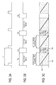
- FIGS. 6A to 6E show signal waveforms
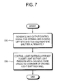
- FIG. 7 is a control flowchart for explaining the control method.
- the pixel P' includes a control transistor 24 connected between the driving transistor 22 and the light emitting layer 25 to control flow of current.
- the control transistor 24 When the control transistor 24 is turned off, the current does not flow in the light emitting layer 25, thereby cutting off the emission.
- the data signal corresponding to the current frame is applied and maintained until a data signal corresponding to the next frame is applied, so that light of the data signal corresponding to the current frame is continuously emitted during one frame.
- the controller 30 controls the control transistor 24 to prevent the emission for the maintained data signal. That is, the controller 30 controls an enable signal En to prevent the current from flowing in the light emitting layer 25 after applying the data signal, thereby turning off the control transistor 24.
- the left-eye shutter and the right-eye shutter are open at a point of time T1 when a 3D video signal 302 corresponding to one frame is applied to the organic light emitting panel 10, and closed at a point of time T2 when an image corresponding to the next frame is applied to the organic light emitting panel 10. That is, the shutters are repetitively open and closed in synchronization with the vertical synchronous signal 300.
- the controller 30 controls the control transistor 24 to prevent the current from flowing in the light emitting layer 25 during a non-emission period TD. As shown in FIG.
- a control method of the display apparatus in this exemplary embodiment is as follows. Similarly to the exemplary embodiment of FIG. 4 , first, at operation S10, the controller 30 controls the signal transmitter 20 to generate and output a control signal for alternately opening and closing the left-eye shutter and the right-eye shutter to be opposite to each other. In this exemplary embodiment, the shutter is open and closed in synchronization with the vertical synchronous signal.
- the controller 30 cuts off the emission of the light emitting layer 25 so that the emission area, where the left-eye image or the right-eye image is displayed while the left-eye shutter or the right-eye shutter is open, moves from top to bottom of the organic light emitting panel 10. That is, the controller 30 controls the control transistor 24 after a lapse of a predetermined emission time TC after an image is scanned to prevent the current from flowing in the light emitting layer 25.
- the controller 30 controls the control transistor 24 after a lapse of a predetermined emission time TC after an image is scanned to prevent the current from flowing in the light emitting layer 25.
- the emission area corresponding to a partial image corresponding to the open shutter is displayed, and the other areas except the emission area enter the non-emission state.
- the display apparatus displays the 3D video signal through the organic light emitting panel 10 having the light emitting layer.
- the shutter glasses 200 are driven by an algorithm to alternately open and close the shutters to be in a state opposite to each other.
- the transistors 23 and 24 formed in the organic light emitting panel 10 are controlled to achieve the non-emission state. That is, the emission state is controlled without inserting a black image or the like data signal change, thereby cutting off the image opposite to the open shutter.
- a display apparatus which can display a 3-D image without a crosstalk, and a control method of the same.
- a display apparatus which can generate a control signal to be transmitted to shutter glasses, and a control method of the same.
Landscapes
- Engineering & Computer Science (AREA)
- Physics & Mathematics (AREA)
- Computer Hardware Design (AREA)
- General Physics & Mathematics (AREA)
- Theoretical Computer Science (AREA)
- Multimedia (AREA)
- Signal Processing (AREA)
- Control Of El Displays (AREA)
- Electroluminescent Light Sources (AREA)
- Control Of Indicators Other Than Cathode Ray Tubes (AREA)
- Testing, Inspecting, Measuring Of Stereoscopic Televisions And Televisions (AREA)
Abstract
Description
- Apparatuses and methods consistent with the inventive concept relate to a display apparatus and a control method of the same, and more particularly, to displaying a three-dimensional (3D) image and a control method of the same.
- A display apparatus processes various kinds of digital and/or analog video signals and displays an image. A user can view a 3D image based on a 3D video signal on a monitor, television (TV), or the like. The 3D video signal is divided into contents for a user's left eye and contents for a right eye, and the divided images are displayed for the left and right eyes, respectively.
- According to a shutter glass method, the shutter glasses are turned on and off to alternately show left and right images so that a user can view the 3D image using the divided images corresponding to the left and right eyes.
- While the left-eye image and the right-eye image are alternately displayed, an opening period of the shutter glasses may needs to be adjusted to prevent crosstalk generated when the left-eye image and the right-eye image are shown to a user at the same time.
- Alternatively, to prevent crosstalk between the left-eye image and the right-eye image and to prevent an afterimage generated on the hold-type display panel, there may be used a control method of closing both the left-eye and right-eye shutters. However, this control method needs the state where both the shutters are closed in addition to two states of the left-eye and right-eye shutters described above (i.e., a case where the right-eye shutter is closed when the left-eye shutter is open, and a case where the right-eye shutter is open when the left-eye shutter is closed). It is, therefore, complicated to generate a control signal involving coding.
- Exemplary embodiments address at least the above problems and/or disadvantages and other disadvantages not described above. Also, exemplary embodiments are not required to overcome the disadvantages described above, and an exemplary embodiment may not overcome any of the problems described above.
- According to one or more exemplary embodiments, there is provided a display apparatus which can display a 3-D image without crosstalk, and a control method of the same. Further, there is provided a display apparatus which can generate a control signal to be transmitted to shutter glasses, and a control method of the same.
- According to an aspect of an exemplary embodiment, there is provided a display apparatus including: an organic light emitting panel which scans a left-eye image and a right-eye image alternately in units of a frame; a signal transmitter which outputs a control signal to external shutter glasses so that a left-eye shutter and a right-eye shutter of the shutter glasses can be open and closed; and a controller which controls the signal transmitter to make open and closed states of the left-eye shutter and the right-eye shutter be opposite to each other, and controls emission of the organic light emitting panel to display an image corresponding to an open shutter but not to display an image opposite to the open shutter when one of the left-eye shutter and the right-eye shutter is open.
- The controller may control the organic light emitting panel to enter a non-emission state while the left-eye image or the right-eye image is scanned to the organic light emitting panel, and to enter an emission state while the left-eye image or the right-eye image is maintained after completely scanned.
- An interval during which the left-eye image or the right-eye image is maintained may include a vertical blank interval.
- The organic light emitting panel may includes a light emitting layer; a switching transistor receiving a data signal corresponding to an image; and a driving transistor connected to the switching transistor and a driving voltage source to which a driving voltage is applied, and allowing a current corresponding to the data signal to flow in the light emitting layer, and the controller may cut off the driving voltage from being applied to the driving transistor during the non-emission state.
- The controller may controls the organic light emitting panel so that an emission area where an image corresponding to the open shutter is displayed can move from an upside to a downside of the organic light emitting panel, but the other areas except the emission area in the organic light emitting panel can enter a non-emission state.
- The organic light emitting panel may include a light emitting layer; a switching transistor receiving a data signal corresponding to an image; a driving transistor connected to the switching transistor and a driving voltage source to which a driving voltage is applied, and allowing a current corresponding to the data signal to flow in the light emitting layer; and a current control transistor connected between the driving transistor and the light emitting layer and controlling a flow of a current, and the controller may control the current control transistor to prevent the current from flowing in the light emitting layer when a predetermined time elapses after the data signal is applied to the switching transistor.
- A period during which the left-eye shutter or the right-eye shutter is open may be equal to a period during which the left-eye shutter or the right-eye shutter is closed.
- A period during which the left-eye shutter or the right-eye shutter is open may be equal to a frame period.
- According to another aspect of an exemplary embodiment, there is provided a display apparatus including: an organic light emitting panel which includes a light emitting layer; a signal transmitter which outputs a control signal so that a right-eye shutter of external shutter glasses can be closed when a left-eye shutter is open and the right-eye shutter is open when the left-eye shutter is closed; and a controller which controls the organic light emitting panel to enter a non-emission state where no image is displayed, when the left-eye image or the right-eye image opposite to the open shutter is scanned or maintained.
- According to another aspect of an exemplary embodiment, there is provided a control method of a display apparatus including an organic light emitting panel which scans a left-eye image and a right-eye image alternately in units of a frame, the control method including: generating and outputting a control signal so that a left-eye shutter and a right-eye shutter of shutter glasses can be open and closed to be opposite to each other; and controlling emission of the organic light emitting panel to display an image corresponding to an open shutter but not to display an image opposite to the open shutter when one of the left-eye shutter and the right-eye shutter is open.
- The above and other aspects will become apparent by describing certain exemplary embodiments with reference to the accompanying drawings, in which:
-
FIG. 1 is a control block diagram of a display apparatus according to an exemplary embodiment; -
FIG. 2 is an equivalent circuit diagram of a pixel in an organic light emitting panel according to an exemplary embodiment; -
FIGS. 3A, 3B, 3C ,3D, and 3E show signal waveforms according to an exemplary embodiment; -
FIG. 4 is a control flowchart for explaining a control method according to an exemplary embodiment; -
FIG. 5 is an equivalent circuit diagram of a pixel in an organic light emitting panel according to another exemplary embodiment; -
FIGS. 6A, 6B, 6C ,6D, and 6E show signal waveforms according to another exemplary; and -
FIG. 7 is a control flowchart for explaining a control method according to another exemplary embodiment. - Exemplary embodiments are described in greater detail below with reference to the accompanying drawings.
- In the following description, like drawing reference numerals are used for like elements, even in different drawings. The matters defined in the description, such as detailed construction and elements, are provided to assist in a comprehensive understanding of the invention. However, the inventive concepts can be practiced without those specifically defined matters. Also, well-known functions or constructions are not described in detail since they would obscure the application with unnecessary detail.
-
FIG. 1 is a control block diagram of a display apparatus according to an exemplary embodiment. As shown, adisplay apparatus 100 includes an organiclight emitting panel 10 including a light emitting layer (not shown), asignal transmitter 20 outputting a control signal toexternal shutter glasses 200, and acontroller 30 controlling the organiclight emitting panel 10 and thesignal transmitter 20. Thedisplay apparatus 100 in this exemplary embodiment may include a TV processing and displaying a broadcasting signal, a monitor connected to a computer, or a portable terminal such as a mobile phone. Thedisplay apparatus 100 may receive and display a two-dimensional (2D) video signal, i.e., a plane image signal, or may receive and display a 3D video signal, i.e., a solid image signal. The 3D video signal is divided according to a left-eye image for a user's left eye and a right-eye image for a user's right eye, and the divided images are sequentially and alternately displayed in units of a frame. - The organic
light emitting panel 10 includes an organic light emitting layer made of an organic material, and corresponds to a self emission panel which can emit light by itself in response to a data signal corresponding to an image. Thus, thedisplay apparatus 100 does not include a backlight assembly required for a liquid crystal display (LCD) panel. In this exemplary embodiment, the organiclight emitting panel 10 is driven by a plurality of transistors included in respective pixels, and corresponds to a hold-type display panel where a once-received data signal is maintained until a data signal corresponding to the next frame is received. The organiclight emitting panel 10 may have an oblong shape. Further, the data signals corresponding to one frame are sequentially scanned in a direction from top to bottom of the organiclight emitting panel 10. - The
signal transmitter 20 generates a control signal to alternately open a left-eye shutter and a right-eye shutter of theshutter glasses 200, and transmits the control signal to theshutter glasses 200. The left-eye image from the 3D video signal is shown to a user's left eye when the left-eye shutter is open, and the right-eye image is shown to a user's right eye when the right-eye shutter is open. Thesignal transmitter 20 may include an infrared transmitter. One of the left-eye shutter or the right-eye shutter is open if an infrared signal output as a control signal has intensity higher than a certain value, and the other one is open if the intensity of the infrared signal is lower than the certain value. Thesignal transmitter 20 may include a wired and/or wireless interface to communicate with theshutter glasses 200. - The
shutter glasses 200 opens and closes the left-eye shutter and the right-eye shutter in synchronization with the control signal output from thesignal transmitter 20. Theshutter glasses 200 may include a liquid crystal shutter. - The
controller 30 controls thesignal transmitter 20 so that the open/closed states of the left-eye shutter and the right-eye shutter are reversed in relation to one another. In this exemplary embodiment, theshutter glasses 200 is configured so that the right-eye shutter is closed when the left-eye shutter is open and the right-eye shutter is open when the left-eye shutter is closed. That is, the open/closed states of the left-eye shutter and the right-eye shutter are reversed in relation to one another, and the shutters are not both open or closed. In this exemplary embodiment, a period during which the shutter is open is equal to that during which the shutter is closed. That is, the shutter is open for a certain time period and closed for the same certain time period. Thus, the shutter alternates between the open state and the closed state. In this exemplary embodiment, the certain time period is a frame period T during which one frame is formed. - The
controller 30 controls emission of the organiclight emitting panel 10 to display an image corresponding to the open shutter and not to display an image opposite to the open shutter when one of the left-eye shutter and the right-eye shutter is open. As described above, data signals corresponding to an image are sequentially scanned to the organiclight emitting panel 10. However, if the emission is cut off by thecontroller 30, the organiclight emitting panel 10 displays no image and thus has an effect as if a black signal is received. An emission state where an image is displayed may be maintained during a certain time period, and a non-emission state where an image is not displayed may be maintained during another certain time period. Alternatively, a certain part of the organiclight emitting panel 10 may emit light, while the other part may emit no light. That is, thecontroller 30 controls theshutter glasses 200 to be open in response to a control signal, and controls the organiclight emitting panel 10 not to emit light if an image opposite to the open shutter is scanned or maintained, thereby preventing crosstalk of an image. - The
controller 30 includes a video signal processor (not shown) to generate a data signal corresponding to an image, and applies various kinds of signals including the data signal to the organiclight emitting panel 10, to drive the organiclight emitting panel 10. Software and hardware configurations for performing functions of thecontroller 30 are described in known technology. -
FIGS. 2 through 4 are views for explaining a control method according to an exemplary embodiment of the display apparatus ofFIG. 1 .FIG. 2 is an equivalent circuit diagram of a pixel in an organic light emitting panel according to an exemplary embodiment of the display apparatus ofFIG. 1 ,FIGS. 3A to 3E show signal waveforms according to an exemplary embodiment of the display apparatus ofFIG. 1 , andFIG. 4 is a control flowchart for explaining a control method according to an exemplary embodiment of the display apparatus ofFIG. 1 . - As shown in
FIG. 2 , a pixel P of the organiclight emitting panel 10 includes a plurality of signal lines and a plurality oftransistors transistor 21 to receive a data signal corresponding to an image and alight emitting layer 25. A drivingtransistor 22 is connected to the switchingtransistor 21 and a drivingvoltage source 210. A driving voltage Vdd is applied to the drivingtransistor 22 and a current corresponding to the data signal flows in thelight emitting layer 25. Additionally, the pixel P includes acapacitor 26 connected between the drivingvoltage source 210 and agate electrode 212 of the drivingtransistor 22 and charged with voltage corresponding to a data signal. Acontrol transistor 23 is connected between the drivingvoltage source 210 and the drivingtransistor 22 to cut off the supply of the driving voltage Vdd. - To be brief, the pixel P is driven as follows. When a gate signal is applied to the switching
transistor 21, the switchingtransistor 21 is turned on to apply the data signal to the pixel P. The data signal charges thecapacitor 26, and turns on the drivingtransistor 22. The current flowing in thelight emitting layer 25 formed between the driving voltage Vdd and the ground Vss is controlled according to the voltage charged in thecapacitor 26. Thelight emitting layer 25 is a current control device which controls light emission depending on the amount of the current. When thecontrol transistor 23 is turned off and the driving voltage Vdd is not applied to the drivingtransistor 22, the drivingtransistor 22 is not driven and no current flows in thelight emitting layer 25. Thecontroller 30 applies an enable signal Vdd-En to control the driving voltage Vdd as a gate signal to thecontrol transistor 23. When thecontroller 30 transmits the enable signal Vdd-En to thecontrol transistor 23, the driving voltage Vdd is applied to the drivingtransistor 22 and thelight emitting layer 25 emits light. That is, thelight emitting layer 25 enters the emission state. When the enable signal Vdd-En is disabled, thelight emitting layer 25 enters the non-emission state. - In this exemplary embodiment, the
controller 30 controls the organiclight emitting panel 10 to enter the non-emission state where no image is displayed while the left-eye or right-eye image corresponding to one frame is scanned on the organiclight emitting panel 10, and controls the organiclight emitting panel 10 to enter the emission state while the completely scanned left-eye or right-eye image is maintained. To enter the non-emission state, thecontroller 30 controls thecontrol transistor 23 not to apply the driving voltage Vdd to the drivingtransistor 22 while an image is scanned. - Referring to
FIG. 3A , an image corresponding to one frame is distinguished by a verticalsynchronous signal 300 per frame period T. As shown inFIG. 3B , the frame period T includes a scanning interval TA where a3D video signal 302 is applied to the organiclight emitting panel 10, and a vertical blank interval (VBI) TB where the scanned image is maintained.FIG. 3C shows an image display state of the organiclight emitting panel 10, i.e., theemission state 310 andnon-emission state 320 of the organiclight emitting panel 10 when an image corresponding to one frame is scanned. The image is scanned in units of a row in adirection 330 from top to bottom of the organiclight emitting panel 10, i.e., applied to the organiclight emitting panel 10 while increasing the number of vertical lines of the organiclight emitting panel 10. InFIG. 3C , a horizontal axis indicates time, and a vertical axis indicates the vertical line of the organiclight emitting panel 10. As shown inFIG. 3C , thecontroller 30 controls thecontrol transistor 23 to make the organiclight emitting panel 10 enter thenon-emission state 320 during the scanning interval TA where the right-eye image is scanned from top to bottom, in thedirection 330, of the organiclight emitting panel 10, and then enter theemission state 310 where the driving voltage Vdd is applied during the VBI, i.e., a maintaining or holding interval TB after the right-eye image is completely scanned. The data signal charged in thecapacitor 26 during the scanning interval TA is displayed on the organiclight emitting panel 10 during the maintaining interval TB. After the right-eye image is displayed, the left-eye image is scanned and displayed by the like process. - Referring to
FIGS. 3D and 3E , agraph 340 and agraph 350 represent states of the right-eye shutter and the left-eye shutter, respectively, that are opposite to each other. One of the right-eye shutter and the left-eye shutter is open (on) during the frame period T and closed (off) during the next frame period T. Thus, a user can view only the right-eye image because the emission state is made only after the right-eye image is completely scanned and then maintained. The same is true for the left-eye image. Further, a user cannot view any image generated when the right-eye and left-eye images are overlapped since the non-emission state is maintained while the right-eye and left-eye images are scanned, i.e., while the right-eye and left-eye images are formed corresponding to one frame. In other words, a user views only the right-eye image when the right-eye shutter is open, and only the left-eye image when the left-eye shutter is open. These images are repeated to show the 3D image. - To allow a user to view an image for a sufficiently long time, a maintaining interval TB may be made long enough for an image to be maintained. Here, the length of the maintaining interval TB may be properly set depending on the size, panel driving speed, etc., of the organic
light emitting panel 10. For example, about 10% to 40% of the frame period may be set as the maintaining interval TB. Thecontroller 30 may include devices other than thecontrol transistor 23 to cut off the driving voltage Vdd, and may cut off the driving voltage Vdd by using the software. Whether the foregoing transistor will be turned on or off may vary depending on the type of the transistor. Also, the high/low of the waveform is not limited to the foregoing description. - Referring to
FIG. 4 , a control method of the display apparatus of an exemplary embodiment is described. - At operation S10, the
controller 30 controls thesignal transmitter 20 to generate and output a control signal for alternately opening/closing the left-eye shutter and the right-eye shutter to be opposite to each other. - At operation S20, the
controller 30 cuts off the supply of the driving voltage Vdd so that the organiclight emitting panel 10 does not emit light while the left-eye or right-eye image is scanned on to the organiclight emitting panel 10, and maintains the supply of the driving voltage Vdd so that the organiclight emitting panel 10 emits light while the completely scanned image is maintained. -
FIGS. 5 through 7 are views for explaining a control method according to another exemplary embodiment of the display apparatus ofFIG. 1 .FIG. 5 is an equivalent circuit diagram of a pixel P' in an organiclight emitting panel 10 according to an exemplary embodiment of the display apparatus ofFIG. 1 ,FIGS. 6A to 6E show signal waveforms, andFIG. 7 is a control flowchart for explaining the control method. - As shown in
FIG. 5 , the pixel P' includes acontrol transistor 24 connected between the drivingtransistor 22 and thelight emitting layer 25 to control flow of current. When thecontrol transistor 24 is turned off, the current does not flow in thelight emitting layer 25, thereby cutting off the emission. - The data signal corresponding to the current frame is applied and maintained until a data signal corresponding to the next frame is applied, so that light of the data signal corresponding to the current frame is continuously emitted during one frame. In this exemplary embodiment, if a predetermined time elapses after applying the data signal to the switching
transistor 21, thecontroller 30 controls thecontrol transistor 24 to prevent the emission for the maintained data signal. That is, thecontroller 30 controls an enable signal En to prevent the current from flowing in thelight emitting layer 25 after applying the data signal, thereby turning off thecontrol transistor 24. - As shown in
FIGS. 6A to 6E , the left-eye shutter and the right-eye shutter are open at a point of time T1 when a3D video signal 302 corresponding to one frame is applied to the organiclight emitting panel 10, and closed at a point of time T2 when an image corresponding to the next frame is applied to the organiclight emitting panel 10. That is, the shutters are repetitively open and closed in synchronization with the verticalsynchronous signal 300. When an emission period TC elapses after an image is applied to the organiclight emitting panel 10, thecontroller 30 controls thecontrol transistor 24 to prevent the current from flowing in thelight emitting layer 25 during a non-emission period TD. As shown inFIG. 6C , since the image is scanned from top to bottom of the organiclight emitting panel 10 in a direction of sequentially increasing the number of vertical lines, it is shown as if anemission area 360 in which the image is displayed moves from top to bottom of the organiclight emitting panel 10. That is, only theemission area 360 corresponding to a partial image of the current frame enters thearea 382 corresponding to an image of the current frame after a lapse of a predetermined time enter the non-emission state. Accordingly, the left-eye image 380 of the previous frame is not shown when the right-eye shutter 340 is open, and the right-eye image 384 of the previous frame is not shown when the left-eye shutter 350 is open. As the speed of applying an image to the organiclight emitting panel 10 increases, the emission time TC becomes longer. - Referring to
FIG. 7 , a control method of the display apparatus in this exemplary embodiment is as follows. Similarly to the exemplary embodiment ofFIG. 4 , first, at operation S10, thecontroller 30 controls thesignal transmitter 20 to generate and output a control signal for alternately opening and closing the left-eye shutter and the right-eye shutter to be opposite to each other. In this exemplary embodiment, the shutter is open and closed in synchronization with the vertical synchronous signal. - At operation S30, the
controller 30 cuts off the emission of thelight emitting layer 25 so that the emission area, where the left-eye image or the right-eye image is displayed while the left-eye shutter or the right-eye shutter is open, moves from top to bottom of the organiclight emitting panel 10. That is, thecontroller 30 controls thecontrol transistor 24 after a lapse of a predetermined emission time TC after an image is scanned to prevent the current from flowing in thelight emitting layer 25. Here, only the emission area corresponding to a partial image corresponding to the open shutter is displayed, and the other areas except the emission area enter the non-emission state. - The display apparatus according to an exemplary embodiment displays the 3D video signal through the organic
light emitting panel 10 having the light emitting layer. Theshutter glasses 200 are driven by an algorithm to alternately open and close the shutters to be in a state opposite to each other. Thetransistors light emitting panel 10 are controlled to achieve the non-emission state. That is, the emission state is controlled without inserting a black image or the like data signal change, thereby cutting off the image opposite to the open shutter. - As described above, there are provided a display apparatus which can display a 3-D image without a crosstalk, and a control method of the same.
- Also, there are provided a display apparatus which can generate a control signal to be transmitted to shutter glasses, and a control method of the same.
- The foregoing exemplary embodiments and advantages are merely exemplary and are not to be construed as limiting the inventive concepts. The present teaching can be readily applied to other types of apparatuses. Also, the description of the exemplary embodiments is intended to be illustrative, and not to limit the scope of the claims, and many alternatives, modifications, and variations will be apparent to those skilled in the art.
Claims (13)
- A display apparatus comprising:an organic light emitting panel which alternately scans a left-eye image and a right-eye image in units of a frame;a signal transmitter which outputs a control signal to external shutter glasses to open or to close a left-eye shutter and a right-eye shutter of the external shutter glasses; anda controller which controls the signal transmitter to make open and closed states of the left-eye shutter and the right-eye shutter to be opposite to each other, and controls emission of the organic light emitting panel to display an image corresponding to an open shutter and not to display an image opposite to the open shutter when one of the left-eye shutter and the right-eye shutter is open.
- The display apparatus according to claim 1, wherein the controller controls the organic light emitting panel to be in a non-emission state while the left-eye image or the right-eye image is being scanned to the organic light emitting panel, and be in an emission state while the left-eye image or the right-eye image is maintained after being completely scanned.
- The display apparatus according to claim 2, wherein an interval during which the left-eye image or the right-eye image is maintained comprises a vertical blank interval.
- The display apparatus according to claim 3, wherein the organic light emitting panel comprises:a light emitting layer;a switching transistor which receives a data signal corresponding to an image;a driving voltage source to supply a driving voltage; anda driving transistor connected to the switching transistor and the driving voltage source to receive the driving voltage so that a current corresponding to the data signal flows in the light emitting layer,wherein the controller cuts off the driving voltage from being supplied to the driving transistor during the non-emission state.
- The display apparatus according to claim 1, wherein the controller controls the organic light emitting panel so that an emission area in which an image corresponding to the open shutter is displayed moves from top to bottom of the organic light emitting panel, and other areas excluding the emission area in the organic light emitting panel be in a non-emission state.
- The display apparatus according to claim 5, wherein the organic light emitting panel comprises:a light emitting layer;a switching transistor which receives a data signal corresponding to an image;a driving voltage source to supply a driving voltage;a driving transistor connected to the switching transistor and the driving voltage source to receive the driving voltage so that a current corresponding to the data signal flows in the light emitting layer; anda control transistor connected between the driving transistor and the light emitting layer to control a flow of the current,wherein the controller controls the control transistor to prevent the current from flowing in the light emitting layer after a lapse of a predetermined time after the data signal is applied to the switching transistor.
- The display apparatus according to claim 1, wherein a time period during which the left-eye shutter or the right-eye shutter is open is equal to a time period during which the left-eye shutter or the right-eye shutter is closed.
- The display apparatus according to claim 7, wherein the time period during which the left-eye shutter or the right-eye shutter is open is equal to a frame period.
- A control method for a display apparatus including an organic light emitting panel which alternately scans a left-eye image and a right-eye image in units of a frame, the control method comprising:generating and outputting a control signal to open or to close a left-eye shutter and a right-eye shutter of shutter glasses alternately to one another; andcontrolling emission of the organic light emitting panel to display an image corresponding to an open shutter and not to display an image opposite to the open shutter when one of the left-eye shutter and the right-eye shutter is open.
- The control method according to claim 9, wherein the controlling the emission comprises controlling the organic light emitting panel to be in a non-emission state while the left-eye image or the right-eye image is being scanned to the organic light emitting panel, and be in an emission state while the left-eye image or the right-eye image is maintained after being completely scanned.
- The control method according to claim 10, wherein the organic light emitting panel comprises a light emitting layer, a switching transistor receiving a data signal corresponding to an image, a driving voltage source to supply a driving voltage, and a driving transistor connected to the switching transistor and the driving voltage source to receive the driving voltage so that a current corresponding to the data signal flows in the light emitting layer, and
the controlling the emission comprises cutting off the driving voltage from being applied to the driving transistor during the non-emission state. - The control method according to claim 9, wherein the controlling the emission comprises controlling an emission area in which the left-eye image or the right-eye image is displayed while the left-eye shutter or the right-eye shutter is open to move from top to bottom of the organic light emitting panel, and controlling other areas excluding the emission area in the organic light emitting panel to be in a non-emission state.
- The control method according to claim 12, wherein the organic light emitting panel comprises a light emitting layer, a switching transistor receiving a data signal corresponding to an image, a driving voltage source to supply a driving voltage, and a driving transistor connected to the switching transistor and the driving voltage source to receive the driving voltage so that a current corresponding to the data signal flows in the light emitting layer, and a control transistor connected between the driving transistor and the light emitting layer and controlling a flow of a current, and the controlling the emission of the organic light emitting panel comprises controlling the control transistor to prevent the current from flowing after a lapse of a predetermined time after the data signal is applied to the switching transistor.
Applications Claiming Priority (1)
| Application Number | Priority Date | Filing Date | Title |
|---|---|---|---|
| KR1020090053224A KR101606832B1 (en) | 2009-06-16 | 2009-06-16 | Display apparatus and control method of the same |
Publications (3)
| Publication Number | Publication Date |
|---|---|
| EP2265033A2 true EP2265033A2 (en) | 2010-12-22 |
| EP2265033A3 EP2265033A3 (en) | 2012-11-07 |
| EP2265033B1 EP2265033B1 (en) | 2017-10-25 |
Family
ID=42937186
Family Applications (1)
| Application Number | Title | Priority Date | Filing Date |
|---|---|---|---|
| EP10154024.3A Not-in-force EP2265033B1 (en) | 2009-06-16 | 2010-02-18 | Stereoscopic display apparatus and control method of the same |
Country Status (4)
| Country | Link |
|---|---|
| US (1) | US8643706B2 (en) |
| EP (1) | EP2265033B1 (en) |
| JP (1) | JP2011002815A (en) |
| KR (1) | KR101606832B1 (en) |
Cited By (1)
| Publication number | Priority date | Publication date | Assignee | Title |
|---|---|---|---|---|
| US20110273441A1 (en) * | 2010-05-10 | 2011-11-10 | Kwang-Sub Shin | Organic light emitting display device and method for driving thereof |
Families Citing this family (22)
| Publication number | Priority date | Publication date | Assignee | Title |
|---|---|---|---|---|
| KR101362771B1 (en) * | 2008-09-17 | 2014-02-14 | 삼성전자주식회사 | Apparatus and method for displaying stereoscopic image |
| KR20110065205A (en) * | 2009-12-09 | 2011-06-15 | 삼성전자주식회사 | Shutter glasses for stereoscopic images and display system including the same |
| WO2011111388A1 (en) * | 2010-03-10 | 2011-09-15 | パナソニック株式会社 | Plasma display device, plasma display system, drive method for plasma display panel, and control method for shutter glasses for plasma display device |
| US9030536B2 (en) | 2010-06-04 | 2015-05-12 | At&T Intellectual Property I, Lp | Apparatus and method for presenting media content |
| US9787974B2 (en) | 2010-06-30 | 2017-10-10 | At&T Intellectual Property I, L.P. | Method and apparatus for delivering media content |
| US8918831B2 (en) | 2010-07-06 | 2014-12-23 | At&T Intellectual Property I, Lp | Method and apparatus for managing a presentation of media content |
| US9049426B2 (en) | 2010-07-07 | 2015-06-02 | At&T Intellectual Property I, Lp | Apparatus and method for distributing three dimensional media content |
| US9560406B2 (en) | 2010-07-20 | 2017-01-31 | At&T Intellectual Property I, L.P. | Method and apparatus for adapting a presentation of media content |
| US9032470B2 (en) | 2010-07-20 | 2015-05-12 | At&T Intellectual Property I, Lp | Apparatus for adapting a presentation of media content according to a position of a viewing apparatus |
| US9232274B2 (en) * | 2010-07-20 | 2016-01-05 | At&T Intellectual Property I, L.P. | Apparatus for adapting a presentation of media content to a requesting device |
| US8994716B2 (en) | 2010-08-02 | 2015-03-31 | At&T Intellectual Property I, Lp | Apparatus and method for providing media content |
| TWI408948B (en) * | 2010-08-16 | 2013-09-11 | Wistron Corp | Method for playing corresponding 3d images according to different visual angles and related image processing system |
| JP5664017B2 (en) * | 2010-08-24 | 2015-02-04 | セイコーエプソン株式会社 | Electro-optical device and electronic apparatus |
| US8438502B2 (en) | 2010-08-25 | 2013-05-07 | At&T Intellectual Property I, L.P. | Apparatus for controlling three-dimensional images |
| US8890860B2 (en) * | 2010-09-10 | 2014-11-18 | Semiconductor Energy Laboratory Co., Ltd. | Stereoscopic EL display device with driving method and eyeglasses |
| KR101824125B1 (en) * | 2010-09-10 | 2018-02-01 | 가부시키가이샤 한도오따이 에네루기 켄큐쇼 | Display device |
| US9602766B2 (en) | 2011-06-24 | 2017-03-21 | At&T Intellectual Property I, L.P. | Apparatus and method for presenting three dimensional objects with telepresence |
| US8947497B2 (en) | 2011-06-24 | 2015-02-03 | At&T Intellectual Property I, Lp | Apparatus and method for managing telepresence sessions |
| US9030522B2 (en) | 2011-06-24 | 2015-05-12 | At&T Intellectual Property I, Lp | Apparatus and method for providing media content |
| US9445046B2 (en) | 2011-06-24 | 2016-09-13 | At&T Intellectual Property I, L.P. | Apparatus and method for presenting media content with telepresence |
| US8587635B2 (en) | 2011-07-15 | 2013-11-19 | At&T Intellectual Property I, L.P. | Apparatus and method for providing media services with telepresence |
| KR102737483B1 (en) * | 2019-08-16 | 2024-12-02 | 엘지전자 주식회사 | Display apparatus and control method thereof |
Family Cites Families (19)
| Publication number | Priority date | Publication date | Assignee | Title |
|---|---|---|---|---|
| JPS6261493A (en) * | 1985-09-11 | 1987-03-18 | Toshiba Corp | Picture display device for stereoscopic vision |
| US5821989A (en) * | 1990-06-11 | 1998-10-13 | Vrex, Inc. | Stereoscopic 3-D viewing system and glasses having electrooptical shutters controlled by control signals produced using horizontal pulse detection within the vertical synchronization pulse period of computer generated video signals |
| JPH10312173A (en) * | 1997-05-09 | 1998-11-24 | Pioneer Electron Corp | Picture display device |
| JP2001112024A (en) | 1999-10-05 | 2001-04-20 | Matsushita Electric Ind Co Ltd | Multiple-lens stereoscopic photographing display device |
| US7742064B2 (en) * | 2001-10-30 | 2010-06-22 | Semiconductor Energy Laboratory Co., Ltd | Signal line driver circuit, light emitting device and driving method thereof |
| US7364306B2 (en) * | 2005-06-20 | 2008-04-29 | Digital Display Innovations, Llc | Field sequential light source modulation for a digital display system |
| US7345659B2 (en) * | 2005-08-09 | 2008-03-18 | Sin-Min Chang | Method and apparatus for stereoscopic display employing an array of pixels each employing an organic light emitting diode |
| US7724211B2 (en) | 2006-03-29 | 2010-05-25 | Nvidia Corporation | System, method, and computer program product for controlling stereo glasses shutters |
| US8169467B2 (en) * | 2006-03-29 | 2012-05-01 | Nvidia Corporation | System, method, and computer program product for increasing an LCD display vertical blanking interval |
| KR101244910B1 (en) * | 2006-04-03 | 2013-03-18 | 삼성전자주식회사 | Time sharing type autostereoscopic display apparatus and method for driving the same |
| US20070247477A1 (en) * | 2006-04-21 | 2007-10-25 | Lowry Gregory N | Method and apparatus for processing, displaying and viewing stereoscopic 3D images |
| EP2015589A1 (en) | 2007-07-13 | 2009-01-14 | Barco NV | Stereo display system with scanning of light valves |
| JP2009122196A (en) * | 2007-11-12 | 2009-06-04 | Toshiba Matsushita Display Technology Co Ltd | Active matrix display device and its driving method |
| CN101878654B (en) | 2007-11-28 | 2013-02-13 | 皇家飞利浦电子股份有限公司 | 3d visualization |
| JP5012729B2 (en) * | 2008-08-08 | 2012-08-29 | ソニー株式会社 | Display panel module, semiconductor integrated circuit, pixel array driving method, and electronic apparatus |
| JP5380996B2 (en) * | 2008-10-10 | 2014-01-08 | ソニー株式会社 | Three-dimensional image system, display device, shutter operation synchronization device of three-dimensional image system, shutter operation synchronization method of three-dimensional image system, and electronic device |
| JP5526029B2 (en) | 2009-01-19 | 2014-06-18 | パナソニック株式会社 | Image display device and image display method |
| JP2010250111A (en) * | 2009-04-16 | 2010-11-04 | Hitachi Ltd | Display device for time division binocular stereoscopic vision |
| KR101056281B1 (en) | 2009-08-03 | 2011-08-11 | 삼성모바일디스플레이주식회사 | Organic electroluminescent display and driving method thereof |
-
2009
- 2009-06-16 KR KR1020090053224A patent/KR101606832B1/en not_active Expired - Fee Related
-
2010
- 2010-01-15 US US12/688,371 patent/US8643706B2/en not_active Expired - Fee Related
- 2010-02-18 EP EP10154024.3A patent/EP2265033B1/en not_active Not-in-force
- 2010-04-05 JP JP2010087366A patent/JP2011002815A/en active Pending
Non-Patent Citations (1)
| Title |
|---|
| None |
Cited By (3)
| Publication number | Priority date | Publication date | Assignee | Title |
|---|---|---|---|---|
| US20110273441A1 (en) * | 2010-05-10 | 2011-11-10 | Kwang-Sub Shin | Organic light emitting display device and method for driving thereof |
| EP2387023A2 (en) * | 2010-05-10 | 2011-11-16 | Samsung Mobile Display Co., Ltd. | Organic light-emitting display device and method for driving thereof |
| US9449548B2 (en) | 2010-05-10 | 2016-09-20 | Samsung Display Co., Ltd. | Organic light emitting display device and method for driving thereof |
Also Published As
| Publication number | Publication date |
|---|---|
| US8643706B2 (en) | 2014-02-04 |
| KR20100134876A (en) | 2010-12-24 |
| KR101606832B1 (en) | 2016-03-29 |
| US20100315494A1 (en) | 2010-12-16 |
| EP2265033A3 (en) | 2012-11-07 |
| EP2265033B1 (en) | 2017-10-25 |
| JP2011002815A (en) | 2011-01-06 |
Similar Documents
| Publication | Publication Date | Title |
|---|---|---|
| US8643706B2 (en) | Display apparatus and control method of the same | |
| US8848041B2 (en) | Method and apparatus for displaying stereoscopic image | |
| US8711139B2 (en) | Method of driving stereoscopic display apparatus and stereoscopic display apparatus | |
| KR101084237B1 (en) | Display device and driving method thereof | |
| TWI541780B (en) | Organic light emitting display device and method for driving thereof | |
| KR101734458B1 (en) | Stereopsis display device and driving method thereof | |
| CN101420629B (en) | Blocking device and electronic display device | |
| JP5172958B2 (en) | Video display system, video display method, and display device | |
| US9025013B2 (en) | Stereoscopic display apparatus for displaying an image with reduced crosstalk and method of driving the same | |
| US20110292041A1 (en) | Stereoscopic display apparatus and method of driving the same | |
| CN101800029B (en) | Electronic imaging device and the method thereof | |
| CN101123734A (en) | 2D/3D image display device, electronic image display device and driving method thereof | |
| JP2011053648A (en) | Display apparatus and method of driving the same | |
| KR101609903B1 (en) | Three-dimensional display device and method of driving same | |
| US9912940B2 (en) | Stereoscopic image display device and method for driving the same | |
| KR20100073321A (en) | 3d image sysytem | |
| KR101724023B1 (en) | Three-dimensional display device and driving method thereof, and data driving apparatus and shutter glasses for three-dimensional display device | |
| KR101761816B1 (en) | Stereoscopic display apparatus and method of driving the same | |
| US9473765B2 (en) | Three-dimensional shutter glasses and grayscale driving method thereof | |
| KR20120062248A (en) | Liquid crystal shutter glasses | |
| KR102217327B1 (en) | Stereoscopic image display and driving method thereof |
Legal Events
| Date | Code | Title | Description |
|---|---|---|---|
| PUAI | Public reference made under article 153(3) epc to a published international application that has entered the european phase |
Free format text: ORIGINAL CODE: 0009012 |
|
| AK | Designated contracting states |
Kind code of ref document: A2 Designated state(s): AT BE BG CH CY CZ DE DK EE ES FI FR GB GR HR HU IE IS IT LI LT LU LV MC MK MT NL NO PL PT RO SE SI SK SM TR |
|
| AX | Request for extension of the european patent |
Extension state: AL BA RS |
|
| RAP1 | Party data changed (applicant data changed or rights of an application transferred) |
Owner name: SAMSUNG ELECTRONICS CO., LTD. |
|
| PUAL | Search report despatched |
Free format text: ORIGINAL CODE: 0009013 |
|
| AK | Designated contracting states |
Kind code of ref document: A3 Designated state(s): AT BE BG CH CY CZ DE DK EE ES FI FR GB GR HR HU IE IS IT LI LT LU LV MC MK MT NL NO PL PT RO SE SI SK SM TR |
|
| AX | Request for extension of the european patent |
Extension state: AL BA RS |
|
| RIC1 | Information provided on ipc code assigned before grant |
Ipc: H04N 13/00 20060101AFI20121002BHEP |
|
| 17P | Request for examination filed |
Effective date: 20130507 |
|
| 17Q | First examination report despatched |
Effective date: 20160928 |
|
| STAA | Information on the status of an ep patent application or granted ep patent |
Free format text: STATUS: EXAMINATION IS IN PROGRESS |
|
| REG | Reference to a national code |
Ref country code: DE Ref legal event code: R079 Ref document number: 602010046140 Country of ref document: DE Free format text: PREVIOUS MAIN CLASS: H04N0013000000 Ipc: H04N0013040000 |
|
| GRAP | Despatch of communication of intention to grant a patent |
Free format text: ORIGINAL CODE: EPIDOSNIGR1 |
|
| STAA | Information on the status of an ep patent application or granted ep patent |
Free format text: STATUS: GRANT OF PATENT IS INTENDED |
|
| INTG | Intention to grant announced |
Effective date: 20170502 |
|
| RIC1 | Information provided on ipc code assigned before grant |
Ipc: H04N 13/04 20060101AFI20170418BHEP Ipc: H04N 13/00 20060101ALI20170418BHEP |
|
| GRAS | Grant fee paid |
Free format text: ORIGINAL CODE: EPIDOSNIGR3 |
|
| GRAA | (expected) grant |
Free format text: ORIGINAL CODE: 0009210 |
|
| STAA | Information on the status of an ep patent application or granted ep patent |
Free format text: STATUS: THE PATENT HAS BEEN GRANTED |
|
| AK | Designated contracting states |
Kind code of ref document: B1 Designated state(s): AT BE BG CH CY CZ DE DK EE ES FI FR GB GR HR HU IE IS IT LI LT LU LV MC MK MT NL NO PL PT RO SE SI SK SM TR |
|
| RAP1 | Party data changed (applicant data changed or rights of an application transferred) |
Owner name: SAMSUNG ELECTRONICS CO., LTD. |
|
| REG | Reference to a national code |
Ref country code: GB Ref legal event code: FG4D |
|
| REG | Reference to a national code |
Ref country code: CH Ref legal event code: EP |
|
| REG | Reference to a national code |
Ref country code: AT Ref legal event code: REF Ref document number: 940927 Country of ref document: AT Kind code of ref document: T Effective date: 20171115 |
|
| REG | Reference to a national code |
Ref country code: DE Ref legal event code: R079 Ref document number: 602010046140 Country of ref document: DE Free format text: PREVIOUS MAIN CLASS: H04N0013040000 Ipc: H04N0013300000 |
|
| REG | Reference to a national code |
Ref country code: IE Ref legal event code: FG4D |
|
| REG | Reference to a national code |
Ref country code: DE Ref legal event code: R096 Ref document number: 602010046140 Country of ref document: DE |
|
| REG | Reference to a national code |
Ref country code: NL Ref legal event code: MP Effective date: 20171025 |
|
| REG | Reference to a national code |
Ref country code: LT Ref legal event code: MG4D |
|
| REG | Reference to a national code |
Ref country code: AT Ref legal event code: MK05 Ref document number: 940927 Country of ref document: AT Kind code of ref document: T Effective date: 20171025 |
|
| PG25 | Lapsed in a contracting state [announced via postgrant information from national office to epo] |
Ref country code: NL Free format text: LAPSE BECAUSE OF FAILURE TO SUBMIT A TRANSLATION OF THE DESCRIPTION OR TO PAY THE FEE WITHIN THE PRESCRIBED TIME-LIMIT Effective date: 20171025 |
|
| PG25 | Lapsed in a contracting state [announced via postgrant information from national office to epo] |
Ref country code: SE Free format text: LAPSE BECAUSE OF FAILURE TO SUBMIT A TRANSLATION OF THE DESCRIPTION OR TO PAY THE FEE WITHIN THE PRESCRIBED TIME-LIMIT Effective date: 20171025 Ref country code: NO Free format text: LAPSE BECAUSE OF FAILURE TO SUBMIT A TRANSLATION OF THE DESCRIPTION OR TO PAY THE FEE WITHIN THE PRESCRIBED TIME-LIMIT Effective date: 20180125 Ref country code: ES Free format text: LAPSE BECAUSE OF FAILURE TO SUBMIT A TRANSLATION OF THE DESCRIPTION OR TO PAY THE FEE WITHIN THE PRESCRIBED TIME-LIMIT Effective date: 20171025 Ref country code: LT Free format text: LAPSE BECAUSE OF FAILURE TO SUBMIT A TRANSLATION OF THE DESCRIPTION OR TO PAY THE FEE WITHIN THE PRESCRIBED TIME-LIMIT Effective date: 20171025 Ref country code: FI Free format text: LAPSE BECAUSE OF FAILURE TO SUBMIT A TRANSLATION OF THE DESCRIPTION OR TO PAY THE FEE WITHIN THE PRESCRIBED TIME-LIMIT Effective date: 20171025 |
|
| PG25 | Lapsed in a contracting state [announced via postgrant information from national office to epo] |
Ref country code: LV Free format text: LAPSE BECAUSE OF FAILURE TO SUBMIT A TRANSLATION OF THE DESCRIPTION OR TO PAY THE FEE WITHIN THE PRESCRIBED TIME-LIMIT Effective date: 20171025 Ref country code: HR Free format text: LAPSE BECAUSE OF FAILURE TO SUBMIT A TRANSLATION OF THE DESCRIPTION OR TO PAY THE FEE WITHIN THE PRESCRIBED TIME-LIMIT Effective date: 20171025 Ref country code: AT Free format text: LAPSE BECAUSE OF FAILURE TO SUBMIT A TRANSLATION OF THE DESCRIPTION OR TO PAY THE FEE WITHIN THE PRESCRIBED TIME-LIMIT Effective date: 20171025 Ref country code: IS Free format text: LAPSE BECAUSE OF FAILURE TO SUBMIT A TRANSLATION OF THE DESCRIPTION OR TO PAY THE FEE WITHIN THE PRESCRIBED TIME-LIMIT Effective date: 20180225 Ref country code: GR Free format text: LAPSE BECAUSE OF FAILURE TO SUBMIT A TRANSLATION OF THE DESCRIPTION OR TO PAY THE FEE WITHIN THE PRESCRIBED TIME-LIMIT Effective date: 20180126 Ref country code: BG Free format text: LAPSE BECAUSE OF FAILURE TO SUBMIT A TRANSLATION OF THE DESCRIPTION OR TO PAY THE FEE WITHIN THE PRESCRIBED TIME-LIMIT Effective date: 20180125 |
|
| REG | Reference to a national code |
Ref country code: DE Ref legal event code: R097 Ref document number: 602010046140 Country of ref document: DE |
|
| PG25 | Lapsed in a contracting state [announced via postgrant information from national office to epo] |
Ref country code: SK Free format text: LAPSE BECAUSE OF FAILURE TO SUBMIT A TRANSLATION OF THE DESCRIPTION OR TO PAY THE FEE WITHIN THE PRESCRIBED TIME-LIMIT Effective date: 20171025 Ref country code: CZ Free format text: LAPSE BECAUSE OF FAILURE TO SUBMIT A TRANSLATION OF THE DESCRIPTION OR TO PAY THE FEE WITHIN THE PRESCRIBED TIME-LIMIT Effective date: 20171025 Ref country code: DK Free format text: LAPSE BECAUSE OF FAILURE TO SUBMIT A TRANSLATION OF THE DESCRIPTION OR TO PAY THE FEE WITHIN THE PRESCRIBED TIME-LIMIT Effective date: 20171025 Ref country code: EE Free format text: LAPSE BECAUSE OF FAILURE TO SUBMIT A TRANSLATION OF THE DESCRIPTION OR TO PAY THE FEE WITHIN THE PRESCRIBED TIME-LIMIT Effective date: 20171025 Ref country code: CY Free format text: LAPSE BECAUSE OF FAILURE TO SUBMIT A TRANSLATION OF THE DESCRIPTION OR TO PAY THE FEE WITHIN THE PRESCRIBED TIME-LIMIT Effective date: 20171025 |
|
| PG25 | Lapsed in a contracting state [announced via postgrant information from national office to epo] |
Ref country code: RO Free format text: LAPSE BECAUSE OF FAILURE TO SUBMIT A TRANSLATION OF THE DESCRIPTION OR TO PAY THE FEE WITHIN THE PRESCRIBED TIME-LIMIT Effective date: 20171025 Ref country code: PL Free format text: LAPSE BECAUSE OF FAILURE TO SUBMIT A TRANSLATION OF THE DESCRIPTION OR TO PAY THE FEE WITHIN THE PRESCRIBED TIME-LIMIT Effective date: 20171025 Ref country code: SM Free format text: LAPSE BECAUSE OF FAILURE TO SUBMIT A TRANSLATION OF THE DESCRIPTION OR TO PAY THE FEE WITHIN THE PRESCRIBED TIME-LIMIT Effective date: 20171025 Ref country code: IT Free format text: LAPSE BECAUSE OF FAILURE TO SUBMIT A TRANSLATION OF THE DESCRIPTION OR TO PAY THE FEE WITHIN THE PRESCRIBED TIME-LIMIT Effective date: 20171025 |
|
| PLBE | No opposition filed within time limit |
Free format text: ORIGINAL CODE: 0009261 |
|
| STAA | Information on the status of an ep patent application or granted ep patent |
Free format text: STATUS: NO OPPOSITION FILED WITHIN TIME LIMIT |
|
| REG | Reference to a national code |
Ref country code: DE Ref legal event code: R119 Ref document number: 602010046140 Country of ref document: DE |
|
| REG | Reference to a national code |
Ref country code: CH Ref legal event code: PL |
|
| PG25 | Lapsed in a contracting state [announced via postgrant information from national office to epo] |
Ref country code: MC Free format text: LAPSE BECAUSE OF FAILURE TO SUBMIT A TRANSLATION OF THE DESCRIPTION OR TO PAY THE FEE WITHIN THE PRESCRIBED TIME-LIMIT Effective date: 20171025 |
|
| 26N | No opposition filed |
Effective date: 20180726 |
|
| REG | Reference to a national code |
Ref country code: IE Ref legal event code: MM4A |
|
| REG | Reference to a national code |
Ref country code: BE Ref legal event code: MM Effective date: 20180228 |
|
| PG25 | Lapsed in a contracting state [announced via postgrant information from national office to epo] |
Ref country code: SI Free format text: LAPSE BECAUSE OF FAILURE TO SUBMIT A TRANSLATION OF THE DESCRIPTION OR TO PAY THE FEE WITHIN THE PRESCRIBED TIME-LIMIT Effective date: 20171025 Ref country code: LU Free format text: LAPSE BECAUSE OF NON-PAYMENT OF DUE FEES Effective date: 20180218 Ref country code: LI Free format text: LAPSE BECAUSE OF NON-PAYMENT OF DUE FEES Effective date: 20180228 Ref country code: CH Free format text: LAPSE BECAUSE OF NON-PAYMENT OF DUE FEES Effective date: 20180228 |
|
| REG | Reference to a national code |
Ref country code: FR Ref legal event code: ST Effective date: 20181031 |
|
| PG25 | Lapsed in a contracting state [announced via postgrant information from national office to epo] |
Ref country code: IE Free format text: LAPSE BECAUSE OF NON-PAYMENT OF DUE FEES Effective date: 20180218 Ref country code: DE Free format text: LAPSE BECAUSE OF NON-PAYMENT OF DUE FEES Effective date: 20180901 |
|
| PG25 | Lapsed in a contracting state [announced via postgrant information from national office to epo] |
Ref country code: BE Free format text: LAPSE BECAUSE OF NON-PAYMENT OF DUE FEES Effective date: 20180228 Ref country code: FR Free format text: LAPSE BECAUSE OF NON-PAYMENT OF DUE FEES Effective date: 20180228 |
|
| PG25 | Lapsed in a contracting state [announced via postgrant information from national office to epo] |
Ref country code: MT Free format text: LAPSE BECAUSE OF NON-PAYMENT OF DUE FEES Effective date: 20180218 |
|
| PG25 | Lapsed in a contracting state [announced via postgrant information from national office to epo] |
Ref country code: TR Free format text: LAPSE BECAUSE OF FAILURE TO SUBMIT A TRANSLATION OF THE DESCRIPTION OR TO PAY THE FEE WITHIN THE PRESCRIBED TIME-LIMIT Effective date: 20171025 |
|
| PGFP | Annual fee paid to national office [announced via postgrant information from national office to epo] |
Ref country code: GB Payment date: 20200123 Year of fee payment: 11 |
|
| PG25 | Lapsed in a contracting state [announced via postgrant information from national office to epo] |
Ref country code: PT Free format text: LAPSE BECAUSE OF FAILURE TO SUBMIT A TRANSLATION OF THE DESCRIPTION OR TO PAY THE FEE WITHIN THE PRESCRIBED TIME-LIMIT Effective date: 20171025 Ref country code: HU Free format text: LAPSE BECAUSE OF FAILURE TO SUBMIT A TRANSLATION OF THE DESCRIPTION OR TO PAY THE FEE WITHIN THE PRESCRIBED TIME-LIMIT; INVALID AB INITIO Effective date: 20100218 |
|
| PG25 | Lapsed in a contracting state [announced via postgrant information from national office to epo] |
Ref country code: MK Free format text: LAPSE BECAUSE OF NON-PAYMENT OF DUE FEES Effective date: 20171025 |
|
| GBPC | Gb: european patent ceased through non-payment of renewal fee |
Effective date: 20210218 |
|
| PG25 | Lapsed in a contracting state [announced via postgrant information from national office to epo] |
Ref country code: GB Free format text: LAPSE BECAUSE OF NON-PAYMENT OF DUE FEES Effective date: 20210218 |