EP2264868A2 - Electrical rotating machine - Google Patents
Electrical rotating machine Download PDFInfo
- Publication number
- EP2264868A2 EP2264868A2 EP10162020A EP10162020A EP2264868A2 EP 2264868 A2 EP2264868 A2 EP 2264868A2 EP 10162020 A EP10162020 A EP 10162020A EP 10162020 A EP10162020 A EP 10162020A EP 2264868 A2 EP2264868 A2 EP 2264868A2
- Authority
- EP
- European Patent Office
- Prior art keywords
- rotor
- housing
- diffusers
- stator
- rotating machine
- Prior art date
- Legal status (The legal status is an assumption and is not a legal conclusion. Google has not performed a legal analysis and makes no representation as to the accuracy of the status listed.)
- Withdrawn
Links
- 238000001816 cooling Methods 0.000 claims abstract description 25
- 230000002093 peripheral effect Effects 0.000 claims abstract description 9
- 238000009434 installation Methods 0.000 claims description 3
- 210000000078 claw Anatomy 0.000 description 19
- 230000004907 flux Effects 0.000 description 5
- 230000000694 effects Effects 0.000 description 4
- 238000003466 welding Methods 0.000 description 4
- 239000000696 magnetic material Substances 0.000 description 3
- 229910000838 Al alloy Inorganic materials 0.000 description 2
- 238000010586 diagram Methods 0.000 description 2
- XEEYBQQBJWHFJM-UHFFFAOYSA-N Iron Chemical group [Fe] XEEYBQQBJWHFJM-UHFFFAOYSA-N 0.000 description 1
- 238000004512 die casting Methods 0.000 description 1
- 239000012212 insulator Substances 0.000 description 1
- 229910052751 metal Inorganic materials 0.000 description 1
- 239000002184 metal Substances 0.000 description 1
- 238000010248 power generation Methods 0.000 description 1
- 238000003825 pressing Methods 0.000 description 1
- 239000011347 resin Substances 0.000 description 1
- 229920005989 resin Polymers 0.000 description 1
- 239000002966 varnish Substances 0.000 description 1
Images


Classifications
-
- H—ELECTRICITY
- H02—GENERATION; CONVERSION OR DISTRIBUTION OF ELECTRIC POWER
- H02K—DYNAMO-ELECTRIC MACHINES
- H02K9/00—Arrangements for cooling or ventilating
- H02K9/02—Arrangements for cooling or ventilating by ambient air flowing through the machine
- H02K9/04—Arrangements for cooling or ventilating by ambient air flowing through the machine having means for generating a flow of cooling medium
- H02K9/06—Arrangements for cooling or ventilating by ambient air flowing through the machine having means for generating a flow of cooling medium with fans or impellers driven by the machine shaft
-
- H—ELECTRICITY
- H02—GENERATION; CONVERSION OR DISTRIBUTION OF ELECTRIC POWER
- H02K—DYNAMO-ELECTRIC MACHINES
- H02K5/00—Casings; Enclosures; Supports
- H02K5/04—Casings or enclosures characterised by the shape, form or construction thereof
- H02K5/20—Casings or enclosures characterised by the shape, form or construction thereof with channels or ducts for flow of cooling medium
- H02K5/207—Casings or enclosures characterised by the shape, form or construction thereof with channels or ducts for flow of cooling medium with openings in the casing specially adapted for ambient air
-
- H—ELECTRICITY
- H02—GENERATION; CONVERSION OR DISTRIBUTION OF ELECTRIC POWER
- H02K—DYNAMO-ELECTRIC MACHINES
- H02K1/00—Details of the magnetic circuit
- H02K1/06—Details of the magnetic circuit characterised by the shape, form or construction
- H02K1/22—Rotating parts of the magnetic circuit
- H02K1/24—Rotor cores with salient poles ; Variable reluctance rotors
- H02K1/243—Rotor cores with salient poles ; Variable reluctance rotors of the claw-pole type
Definitions
- the present invention relates to an electrical rotating machine including a cooling fan.
- an electrical rotating machine with a built-in fan grows in demand.
- a conventional electrical rotating machine cannot compensate for a temperature increased by self-heat generation.
- JP-9-172752-A page 6 [0041-0046], Figs. 1 and 2
- Figs. 1 and 2 describes a generator having a plurality of rectifying guides (hereinafter referred to as diffusers) on an inner wall surface of a corner portion of a frame (housing) that forms a stator.
- Figs. 1 and 2 of JP-9-172752-A adjacent pairs of the rectifying guides are arranged at equal intervals, and the rectifying guides are inclined at a predetermined angle toward a rotational direction of a cooling fan with respect to a radial direction of a shaft, thereby improving the effect of adjusting cooling air.
- the diffusers are inclined toward a rotational direction of a rotor. That is, the cooling air generated by the cooling fan is discharged toward the outside of the generator in a direction nearly perpendicular to the direction in which the diffusers are inclined. Thus, airflow resistance is increased by the diffusers.
- the cooling air cannot be efficiently discharged from a plurality of discharge ports circumferentially arranged on outer peripheral portions of front and rear housings. Therefore, a stator coil cannot be sufficiently cooled.
- An object of the present invention is to provide an electrical rotating machine that uses a built-in cooling fan to exhibit improved performance in cooling a stator coil.
- the electrical rotating machine includes: a rotor having a cooling fan on an end face of the rotor; a stator that is arranged opposite the rotor and has an stator coil with a rotation clearance provided between the stator and the rotor; a housing that holds the rotor and the stator; a plurality of intake ports that are provided in a side wall portion of the housing; a plurality of discharge ports that are provided circumferentially in an outer peripheral portion of the housing; and/or a plurality of diffusers that are provided circumferentially on an inner wall surface of a corner portion of the housing, the diffusers inclining toward the side opposite to a rotational direction of the rotor.
- the present invention provides the electrical rotating machine that uses a built-in cooling fan to exhibit improved performance in cooling a stator coil.
- each of a front housing 1 and a rear housing 2 has an inner storage space and a bottom surface and is formed in a cylindrical shape or bowl shape.
- the front housing 1 has a fixing section 3 integrated with the front housing 1.
- the rear housing 2 has a fixing section 4 integrated with the rear housing 2.
- Each of the fixing sections 3 and 4 has a fixing hole.
- the fixing section 3 protrudes on an outer circumferential side of the front housing 1 in a radial direction of the front housing 1.
- the fixing section 4 protrudes on an outer circumferential side of the rear housing 2 in a radial direction of the front housing 2.
- the fixing sections 3 and 4 are attached to a vehicle by means of bolts (not shown).
- Each of the front and rear housings 1 and 2 is made of an aluminum alloy and molded by die casting.
- a rear cover 5 is attached to one of end portions (separated from each other in the direction of a rotational axis of the rear housing 2) of the rear housing 2 and is thinner than each of the front and rear housings 1 and 2.
- the rear cover 5 has an inner storage space and a bottom surface and is formed in a cylindrical shape or bowl shape in a similar fashion to the housings.
- the rear cover 5 has a plurality of intake ports (openings) 5a on inner and outer circumferential sides thereof. Air flows through the intake ports 5a.
- a terminal 6 to be connected to a battery is attached to the outer circumferential side of the rear cover 5.
- the rear cover 5 is made of resin or an aluminum alloy.
- a ball bearing 7a is attached to one of outer end portions (separated from each other in the direction of a rotational axis of the front housing 1) of the front housing 1 and located near the radial center of the front housing 1, while a ball bearing 7b is attached to one of outer end portions (separated from each other in the direction of the rotational axis of the rear housing 2) of the rear housing 2 and located near the radial center of the rear housing 2.
- the diameter of the ball bearing 7a is larger than the diameter of the ball bearing 7b.
- a shaft 8 extends through an inner ring of the ball bearing 7a and an inner ring of the ball bearing 7b.
- the shaft 8 is capable of rotating relative to the front and rear housings 1 and 2 and held by the ball bearings 7a and 7b.
- a pulley 9 is fixed to the shaft 8 by a bolt on the side of the front housing 1 so that the shaft 8 and the pulley 9 are capable of rotating in an integrated manner.
- the pulley 9 serves as a rotation transfer member.
- a rotation of an engine (not shown) is transferred to a crank pulley. Then, the rotation of the engine is transferred from the crank pulley to the pulley 9 through a belt that serves as an endless transfer belt.
- the shaft 8 is rotated by the rotation of the pulley 9.
- the rotational rate of the shaft 8 is proportional to the rotational rate of the engine and a pulley ratio of the pulley 9 and the crank pulley.
- Two slip rings 10 are attached to an end portion of the shaft 8 on the side of the rear housing 2 so that the slip rings 10 and the shaft 8 are capable of rotating in an integrated manner. Power is supplied through two brushes 11 to the slip rings 10. The brushes 11 slide while being pushed by the respective slit rings 10.
- a front rotor core 12F and a rear rotor core 12R join the shaft 8 in a serrated manner at a substantially central portion (in the direction of a rotational axis of the shaft 8) of the shaft 8 so that the rotor cores 12F and 12R and the shaft 8 are capable of rotating in an integrated manner.
- the front rotor core 12F joins a portion of the shaft 8
- the rear rotor core 12R joins another portion of the shaft 8.
- Each of the rotor cores 12F and 12R is made of a magnetic material and molded.
- An outer end portion of the front rotor core 12F plastically flows in an annular groove 8a formed in the shaft 8 so that a movement of the front rotor core 12F in the direction of the rotational axis of the shaft 8 is restricted under the condition that the rotor cores 12F and 12R face each other in the direction of the rotational axis of the shaft 8 and are in contact with each other.
- An outer end portion of the rear rotor core 12R plastically flows in an annular groove 8b formed in the shaft 8 so that a movement of the rear rotor core 12R in the direction of the rotational axis of the shaft 8 is restricted under the condition that the rotor cores 12F and 12R face each other in the direction of the rotational axis of the shaft 8 and are in contact with each other.
- the front-side and rear rotor cores 12F and 12R fixed to the shaft 8 in the above-described way form a rotor 12.
- a plate-shaped front fan 13F and a plate-shaped rear fan 13R are attached to respective end faces (separated from each other in the direction of a rotational axis of the rotor 12) of the rotor 12.
- the front fan 13F has a plurality of blades on an outer circumferential side of the front fan 13F.
- the rear fan 13R has a plurality of blades on an outer circumferential side of the rear fan 13R.
- the fans 13F and 13R and the rotor 12 rotate in an integrated manner.
- Each of the front rotor core 12F and the rear rotor core 12R includes a shaft portion 12a and a plurality of rotor core claw magnetic poles 12b.
- the shaft portions 12a are located on inner sides of the rotor cores 12F and 12R.
- the rotor core claw magnetic poles 12b are located on outer sides of the rotor cores 12F and 12R.
- Each of the rotor core claw magnetic poles 12b has an L shape in a cross section taken along a radial direction of the rotor 12.
- One of ends (separated from each other in the direction of the rotational axis of the rotor 12) of the shaft portion 12a of the rotor member 12F faces and is in contact with one of ends (separated from each other in the direction of the rotational axis of the rotor 12) of the shaft portion 12a of the rotor member 12R so that the front rotor core 12F and the rear rotor core 12R form a Lundell-type iron core.
- a field coil 14 is provided between outer circumferences of the shaft portions 12a and inner circumferences of the rotor core claw magnetic poles 12b and wound around the rotational axis of the rotor 12. Both ends of the field coil 14 extend along the shaft 8 and are connected to the respective two slip rings 10.
- the brushes 11 supply field currents through the slip rings 10 to the field coil 14.
- the currents (that are to be supplied to the field coil 14) are controlled on the basis of the state of the battery so that when a generated voltage is higher than a voltage of the battery included in the vehicle, power generation starts.
- An IC regulator (not shown) controls the generated voltage so that a voltage applied to the terminal 6 is constant.
- the IC regulator is located in a rectification circuit 15 (described later) provided in the rear cover 5 and serves as a voltage control circuit.
- a stator 17 is sandwiched between the front housing 1 and the rear housing 2 and fixed to the front housing 1 and the rear housing 2.
- An inner circumference of the stator 17 faces outer circumferences of the rotor core claw magnetic poles 12b while there are small gaps between the inner circumference of the stator 17 and the outer circumferences of the rotor core claw magnetic poles 12b.
- the stator 17 includes a stator core 17a and a stator coil 17b.
- the stator core 17a is made of a magnetic material.
- the stator coil 17b is wound around the stator core 17a.
- the stator coil 17b of each phase is connected to the rectification circuit 15 located in the rear cover 5.
- the rectification circuit 15 is connected to the battery through the terminal 6.
- the rectification circuit 15 includes a plurality of rectifier.
- the rectifiers form a three-phase coil.
- six rectifiers perform full-wave rectification.
- the rotor 12 is described below in detail.
- the front rotor core 12F and the rear rotor core 12R form the rotor 12.
- Each of the rotor cores 12F and 12R includes the plurality of rotor core claw magnetic poles 12b (specifically, six claw magnetic poles 12b) arranged in the circumferential direction of the rotor 12.
- the rotor core claw magnetic poles 12b are located on the outer sides of the shaft portions 12a and have an L shape in the cross section taken along the radial direction of the rotor 12.
- the rotor core claw magnetic poles 12b (extending from the front rotor core 12F) and the rotor core claw magnetic poles 12b (extending from the rear rotor core 12R) are alternately arranged in the circumferential direction of the rotor 12.
- the number of all the rotor core claw magnetic poles 12b is 12 in the present embodiment.
- the front rotor core 12F and the rear rotor core 12R are fixed to the shaft 8 under the condition that: the field coil 14 is located between the shaft portions 12a and the rotor core claw magnetic poles 12b; the rotor core claw magnetic poles 12b (extending from the front rotor core 12F) and the rotor core claw magnetic poles 12b (extending from the rear rotor core 12R) are alternately arranged in the circumferential direction of the rotor 12; and the end of the shaft portion 12a of the rotor member 12F is in contact with the end of the shaft portion 12a of the rotor member 12R.
- the front fan 13F serves as a cooling fan and is attached to one of outer ends (separated from each other in the direction of the rotational axis of the rotor 12) of the front rotor core 12F by welding or the like.
- the rear fan 13R serves as a cooling fan and is attached to one of outer ends (separated from each other in the direction of the rotational axis of the rotor 12) of the rear rotor core 12R by welding or the like.
- the front fan 13F and the rear fan 13R are arranged so that air flows toward a central portion of the rotor 12 due to the rotation of the rotor 12.
- the front fan 13F has the blades integrated with the front fan 13F.
- the rear fan 13R has the blades integrated with the rear fan 13R.
- Each of the blades is a protruding portion and made of a metal plate.
- the blades included in the front fan 13F are arranged in the circumferential direction of the front fan 13F, while the blades included in the rear fan 13R are arranged in the circumferential direction of the rear fan 13R.
- the blades arranged in a part of the circumference of each of the fans 13F and 13R are formed in a substantially arc shape and bent at a substantially right angle by pressing and have a surface inclined to the radial direction of the fan.
- the front fan 13F is fixed to the outer end (of the two outer ends separated from each other in the direction of the rotational axis of the rotor 12) of the front rotor core 12F in an integrated manner by welding.
- the rear fan 13R is fixed to the outer end (of the two outer ends separated from each other in the direction of the rotational axis of the rotor 12) of the rear rotor core 12R in an integrated manner by welding.
- the front fan 13F, the rear fan 13R, and the rotor 12 allow air to flow.
- the stator core 17a has thin plates that are laminated and formed in a coil-like shape. Each of the thin plate included in the stator core 17a is made of a magnetic material.
- the stator core 17a also has a plurality of slots (not shown) in an inner circumferential surface of the stator core 17a. The number of the slots are determined on the basis of the number of the rotor core claw magnetic poles 12b and arranged at equal intervals.
- the three-phase pre-wound stator coil 17b is inserted in the slots and connected by Y-connection or triangle connection. Insulator sheets (that are insulating members) are inserted in the slots to prevent the stator coil 17b inserted in the slots from being exposed to the inner circumferential surface of the stator core 17b.
- the number of magnetic poles that are provided for one phase and included in the stator 17 is 12 and the same as the number of the magnetic poles included in the rotor 12.
- stator coil 17b The surface of the stator coil 17b is coated by varnish or the like to cause the stator coil 17b to be insulated.
- a terminal of the stator coil 17b passes through the rear housing 2 and is connected to a terminal 15a of the rectification circuit 15.
- An insulating paper (that is an insulating member) may be arranged between the stator core 17a and the stator coil 17b.
- the front housing 1 has a plurality of intake ports 1C formed in a side wall portion of the front housing 1
- the rear housing 2 has a plurality of intake ports 2c formed in a side wall portion of the rear housing 2, as shown in Figs. 1 to 3 . Air flows through the intake ports 1C and the intake ports 2c.
- an outer radius ⁇ D11 indicates a distance between the rotational axis of the rotor 12 and a point (that is the farthest point from the rotational axis of the rotor 12 among all points of each intake port 1c) of each of the intake ports 1c
- a outer radius ⁇ D21 indicates a distance between the rotational axis of the rotor 12 and a point (that is the farthest point from the rotational axis of the rotor 12 among all points of each intake port 2c) of each of the intake ports 2c.
- a radius ⁇ D12 indicates an inner radius of each of the blades included in the front fan 13F (attached to the end face of the rotor 12 having the housings 1 and 2 that face each other).
- a radius ⁇ D22 indicates an inner radius of each of the blades included in the rear fan 13R (attached to the other end face of the rotor 12 having the housings 1 and 2 that face each other).
- the radius ⁇ D11 is equal to or smaller than the radius ⁇ D12.
- the radius ⁇ D21 is equal to or smaller than the radius ⁇ D22.
- the front housing 1 has a plurality of discharge ports (openings) 1d on the outer circumferential side of the front housing 1.
- the discharge ports 1d are arranged in the circumferential direction of the front housing 1.
- the rear housing 2 has a plurality of discharge ports (openings) 2d on the outer circumferential side of the rear housing 2.
- the discharge ports 2d are arranged in the circumferential direction of the rear housing 2.
- a radius ⁇ D13 of a bottom end of each discharge port 1d indicates a distance between the rotational axis of the rotor 12 and a point (that is the closest point from the rotational axis of the rotor 12 among all points of the discharge port 1d) of the discharge port 1d
- a radius ⁇ D23 of a bottom end of each discharge port 2d indicates a distance between the rotational axis of the rotor 12 and a point (that is the closest point from the rotational axis of the rotor 12 among all points of the discharge port 2d) of the discharge port 2d.
- a radius ⁇ D14 indicates an outer radius of each blade included in the front fan 13F.
- a radius ⁇ D24 indicates an outer radius of each blade included in the rear fan 13R.
- the radius ⁇ D13 is equal to or larger than the radius ⁇ D14.
- the radius ⁇ D23 is equal to or larger than the radius ⁇ D24.
- a plurality of diffusers 1a circumferentially provided are formed integrally with an inner wall surface 1E of a corner portion of the front housing 1.
- a plurality of diffusers 2a circumferentially provided are formed integrally with an inner wall surface 2E of a corner portion of the rear housing 2.
- the diffusers 1a are inclined at a predetermined angle ⁇ 1, and the diffusers 2a are inclined at a predetermined angle ⁇ 2.
- the diffusers 1a and 2a are inclined toward the side opposite to the rotational direction of the rotor 12. That is, the diffusers 1a are inclined toward the same direction as an inclination (angle) ⁇ 3 of each of the blades included in the front fan 13F, and the diffusers 2a are inclined toward the same direction as an inclination (angle) ⁇ 4 of each of the blades included in the rear fan 13R.
- the angle ⁇ 1 is determined on the basis of the inclination angle ⁇ 3, and the angle ⁇ 2 is determined on the basis of the inclination angle ⁇ 4.
- the diffusers 1a are located on the outer side of the front housing 1 with respect to the outer radius ⁇ D14 of the front fan 13F.
- the diffusers 2a are located on the outer side of the rear housing 2 with respect to the outer radius ⁇ D24 of the rear fan 13R.
- Reference symbol ⁇ p1 denotes the interval at which the diffusers 1a are arranged, as shown in Fig. 5 .
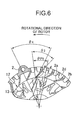
- Reference symbol ⁇ p2 denotes the interval at which the diffusers 2a are arranged, as shown in Fig. 6 .
- the front housing 1a has ribs 1b that form the discharge ports 1d, while the rear housing 2a has ribs 2b that form the discharge ports 2d.
- the discharge ports 1d are located circumferentially on the outer peripheral portion of the front housing 1.
- the discharge ports 2d are located circumferentially on the outer peripheral portion of the rear housing 2.
- the diffusers 1a extend to the respective ribs 1b as shown in Fig. 5
- the diffusers 2a extend to the respective ribs 2b as shown in Fig. 6 .
- the ribs 1b are farther from the rotational axis of the rotor 12 than the bottom ends of the discharge ports 1d, while the ribs 2b are farther from the rotational axis of the rotor 12 than the bottom ends of the discharge ports 2d.
- the diffusers 1a may be arranged at different intervals in the circumferential direction of the front housing 1. If an obstacle such as a hole or a screw, which disturbs installation of the diffusers 2a, is present and overlaps any one or more of the diffusers 2a, then the diffusers 2a may be arranged at different intervals in the circumferential direction of the rear housing 2.
- the interval ⁇ p1 of the diffusers 1a is determined on the basis of the ribs 1b and the interval of the blades included in the front fan 13F.
- the interval ⁇ p2 of the diffusers 2a is determined on the basis of the ribs 2b and the interval of the blades included in the rear fan 13R.
- the rotation of the engine is transferred from a crank shaft through the belt to the pulley 9.
- the pulley 9 rotates the rotor 12 through the shaft 8.
- the brushes 11 supply a direct current through the slip rings 10 to the field coil 14 located in the rotor 12
- a magnetic flux is generated around inner and outer circumferences of the field coil 14.
- a north pole or a south pole is alternately formed at the rotor core claw magnetic poles 12b (included in the rotor 12) in the circumferential direction of the rotor 12.
- the magnetic flux generated by the field coil 14 circles from the rotor core claw magnetic poles 12b (north poles) included in the front rotor core 12F to the stator coil 17b included in the stator 17.
- the magnetic flux reaches the rotor core claw magnetic poles 12b (south poles) included in the rear rotor core 12R.
- the magnetic flux forms a magnetic circuit extending to the rotor 12 and the stator 17. Since the magnetic flux generated by the rotor 12 intersects the stator coil 17b, an alternating current induced voltage is produced across the U-phase, V-phase, and W-phase stator coil 17b. Thus, the three-phase alternating current induced voltage is produced.
- the alternating current voltage produced in the aforementioned way is full-wave rectified and converted into a direct current voltage by the rectification circuit 15.
- the IC regulator (not shown) controls a current to be supplied to the field coil 14 so that the rectified direct current voltage is approximately 14.3 V and constant.
- FIG. 1 airflow shown by arrows (broken lines) of Fig. 1 is formed.
- the air flow is directed from the outside of the generator into the generator in the axial direction and directed to the outside of the generator in the outer circumferential direction.
- the front fan 13F rotates to take air from the outside of the generator in the axial direction through the intake ports 1c (located in an outer circumferential portion of the ball bearing 7a attached to the front housing 1).
- the intake ports 1c located in an outer circumferential portion of the ball bearing 7a attached to the front housing 1.
- the flow of the air is adjusted by the diffusers 1a as shown by arrows (broken lines) of Fig. 5 .
- the air is then discharged from the discharge ports 1d located circumferentially in the outer peripheral portion of the front housing 1.
- the diffusers 1a also serves as heat releasing fins. In the present embodiment, since the diffusers 1a are inclined toward the side opposite to the rotational direction of the rotor 12, the cooling effect is improved.
- the rear fan 13R rotates to take air from the outside of the generator in the axial direction through the intake ports 5a (formed in an outer end portion of the rear cover 5), holes (that are open and formed in end faces (separated from each other in the axial direction) of the rear cover 5 on the inner circumferential side), the rectification circuit 15, and the intake ports 2c (formed in an outer circumferential portion of the ball bearing 7b attached to the rear housing 2).
- the air taken by the rear fan 13R flows toward the outer circumference of the rear housing 2 due to a centrifugal force generated by the blades of the rear fan 13R, the flow of the air is adjusted by the diffusers 2a as shown by arrows (broken lines) of Fig. 6 .
- the air is then discharged from the discharge ports 2d that are located circumferentially in the outer peripheral portion of the rear housing 2.
- the heat generated by the stator 17 and the heat transferred to the rear housing 2 are released from the surface of the rear housing 2 in the same way of the front housing 1.
- the stator coil 17b included in the stator 17 can be cooled by the air that flows toward the discharge port 2d.
- the diffusers 2a also serves as heat releasing fins. In the present embodiment, since the diffusers 2a are inclined toward the side opposite to the rotational direction of the rotor 12, the cooling effect is improved.
- Rotation of the fans 13F and 13R produces a difference between pressure applied to the front fan 13F and pressure applied to the rear fan 13R.
- the pressure difference causes air to flow between the magnetic poles of the rotor 12 and between the rotor 12 and the stator 17.
- the pressure applied to the rear fan 13R becomes large, air flows from the side of the front housing 1 through a gap between the rotor 12 and the stator 17 and a gap between the magnetic poles included in the rotor 12 toward the side of the rear housing 2 so that the rotor 12 and the stator 17 are cooled.
Landscapes
- Engineering & Computer Science (AREA)
- Power Engineering (AREA)
- Motor Or Generator Cooling System (AREA)
- Motor Or Generator Frames (AREA)
- Synchronous Machinery (AREA)
Abstract
Description
- The present invention relates to an electrical rotating machine including a cooling fan.
- In order to reduce the size of an electrical rotating machine and increase power of the electrical rotating machine, an electrical rotating machine with a built-in fan grows in demand. A conventional electrical rotating machine cannot compensate for a temperature increased by self-heat generation.
- To avoid this,
JP-9-172752-A Figs. 1 and2 ) describes a generator having a plurality of rectifying guides (hereinafter referred to as diffusers) on an inner wall surface of a corner portion of a frame (housing) that forms a stator. - In
Figs. 1 and2 ofJP-9-172752-A - According to
JP-9-172752-A - An object of the present invention is to provide an electrical rotating machine that uses a built-in cooling fan to exhibit improved performance in cooling a stator coil.
- A desirable aspect of the present invention is described below to solve the aforementioned problem.
- The electrical rotating machine includes: a rotor having a cooling fan on an end face of the rotor; a stator that is arranged opposite the rotor and has an stator coil with a rotation clearance provided between the stator and the rotor; a housing that holds the rotor and the stator; a plurality of intake ports that are provided in a side wall portion of the housing; a plurality of discharge ports that are provided circumferentially in an outer peripheral portion of the housing; and/or a plurality of diffusers that are provided circumferentially on an inner wall surface of a corner portion of the housing, the diffusers inclining toward the side opposite to a rotational direction of the rotor.
- The present invention provides the electrical rotating machine that uses a built-in cooling fan to exhibit improved performance in cooling a stator coil.
-
-
Fig. 1 is a vertical cross sectional view of an alternator for a vehicle. -
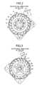
Fig. 2 is a diagram showing a back surface of a front housing (when viewed from the side opposite to the side of a pulley). -
Fig. 3 is a diagram showing a back surface of a rear housing (when viewed from the side of the pulley). -
Fig. 4 is a vertical cross sectional view of the alternator. -
Fig. 5 is a left side view of main parts of the alternator (when viewed from the side of the pulley). -
Fig. 6 is a right side view of main parts of the alternator (when viewed from the opposite side of the pulley). - An embodiment of the present invention is described below with reference to
Figs. 1 to 6 . - As shown in
Fig. 1 , each of afront housing 1 and arear housing 2 has an inner storage space and a bottom surface and is formed in a cylindrical shape or bowl shape. Thefront housing 1 has afixing section 3 integrated with thefront housing 1. Therear housing 2 has afixing section 4 integrated with therear housing 2. Each of thefixing sections fixing section 3 protrudes on an outer circumferential side of thefront housing 1 in a radial direction of thefront housing 1. Thefixing section 4 protrudes on an outer circumferential side of therear housing 2 in a radial direction of thefront housing 2. Thefixing sections rear housings - A
rear cover 5 is attached to one of end portions (separated from each other in the direction of a rotational axis of the rear housing 2) of therear housing 2 and is thinner than each of the front andrear housings rear cover 5 has an inner storage space and a bottom surface and is formed in a cylindrical shape or bowl shape in a similar fashion to the housings. Therear cover 5 has a plurality of intake ports (openings) 5a on inner and outer circumferential sides thereof. Air flows through theintake ports 5a. Aterminal 6 to be connected to a battery is attached to the outer circumferential side of therear cover 5. Therear cover 5 is made of resin or an aluminum alloy. - A ball bearing 7a is attached to one of outer end portions (separated from each other in the direction of a rotational axis of the front housing 1) of the
front housing 1 and located near the radial center of thefront housing 1, while a ball bearing 7b is attached to one of outer end portions (separated from each other in the direction of the rotational axis of the rear housing 2) of therear housing 2 and located near the radial center of therear housing 2. The diameter of the ball bearing 7a is larger than the diameter of the ball bearing 7b. - A
shaft 8 extends through an inner ring of the ball bearing 7a and an inner ring of the ball bearing 7b. Theshaft 8 is capable of rotating relative to the front andrear housings ball bearings - A
pulley 9 is fixed to theshaft 8 by a bolt on the side of thefront housing 1 so that theshaft 8 and thepulley 9 are capable of rotating in an integrated manner. Thepulley 9 serves as a rotation transfer member. A rotation of an engine (not shown) is transferred to a crank pulley. Then, the rotation of the engine is transferred from the crank pulley to thepulley 9 through a belt that serves as an endless transfer belt. Theshaft 8 is rotated by the rotation of thepulley 9. The rotational rate of theshaft 8 is proportional to the rotational rate of the engine and a pulley ratio of thepulley 9 and the crank pulley. - Two
slip rings 10 are attached to an end portion of theshaft 8 on the side of therear housing 2 so that theslip rings 10 and theshaft 8 are capable of rotating in an integrated manner. Power is supplied through two brushes 11 to theslip rings 10. The brushes 11 slide while being pushed by therespective slit rings 10. - A
front rotor core 12F and a rear rotor core 12R join theshaft 8 in a serrated manner at a substantially central portion (in the direction of a rotational axis of the shaft 8) of theshaft 8 so that therotor cores 12F and 12R and theshaft 8 are capable of rotating in an integrated manner. In this case, thefront rotor core 12F joins a portion of theshaft 8, while the rear rotor core 12R joins another portion of theshaft 8. Each of therotor cores 12F and 12R is made of a magnetic material and molded. An outer end portion of thefront rotor core 12F plastically flows in anannular groove 8a formed in theshaft 8 so that a movement of thefront rotor core 12F in the direction of the rotational axis of theshaft 8 is restricted under the condition that therotor cores 12F and 12R face each other in the direction of the rotational axis of theshaft 8 and are in contact with each other. An outer end portion of the rear rotor core 12R plastically flows in anannular groove 8b formed in theshaft 8 so that a movement of the rear rotor core 12R in the direction of the rotational axis of theshaft 8 is restricted under the condition that therotor cores 12F and 12R face each other in the direction of the rotational axis of theshaft 8 and are in contact with each other. The front-side andrear rotor cores 12F and 12R fixed to theshaft 8 in the above-described way form arotor 12. - A plate-shaped
front fan 13F and a plate-shapedrear fan 13R are attached to respective end faces (separated from each other in the direction of a rotational axis of the rotor 12) of therotor 12. Thefront fan 13F has a plurality of blades on an outer circumferential side of thefront fan 13F. Therear fan 13R has a plurality of blades on an outer circumferential side of therear fan 13R. Thefans rotor 12 rotate in an integrated manner. - Each of the
front rotor core 12F and the rear rotor core 12R includes ashaft portion 12a and a plurality of rotor core clawmagnetic poles 12b. Theshaft portions 12a are located on inner sides of therotor cores 12F and 12R. The rotor core clawmagnetic poles 12b are located on outer sides of therotor cores 12F and 12R. Each of the rotor core clawmagnetic poles 12b has an L shape in a cross section taken along a radial direction of therotor 12. One of ends (separated from each other in the direction of the rotational axis of the rotor 12) of theshaft portion 12a of therotor member 12F faces and is in contact with one of ends (separated from each other in the direction of the rotational axis of the rotor 12) of theshaft portion 12a of the rotor member 12R so that thefront rotor core 12F and the rear rotor core 12R form a Lundell-type iron core. Afield coil 14 is provided between outer circumferences of theshaft portions 12a and inner circumferences of the rotor core clawmagnetic poles 12b and wound around the rotational axis of therotor 12. Both ends of thefield coil 14 extend along theshaft 8 and are connected to the respective two slip rings 10. The brushes 11 supply field currents through the slip rings 10 to thefield coil 14. The currents (that are to be supplied to the field coil 14) are controlled on the basis of the state of the battery so that when a generated voltage is higher than a voltage of the battery included in the vehicle, power generation starts. An IC regulator (not shown) controls the generated voltage so that a voltage applied to theterminal 6 is constant. The IC regulator is located in a rectification circuit 15 (described later) provided in therear cover 5 and serves as a voltage control circuit. - A
stator 17 is sandwiched between thefront housing 1 and therear housing 2 and fixed to thefront housing 1 and therear housing 2. An inner circumference of thestator 17 faces outer circumferences of the rotor core clawmagnetic poles 12b while there are small gaps between the inner circumference of thestator 17 and the outer circumferences of the rotor core clawmagnetic poles 12b. - The
stator 17 includes astator core 17a and a stator coil 17b. Thestator core 17a is made of a magnetic material. The stator coil 17b is wound around thestator core 17a. The stator coil 17b of each phase is connected to therectification circuit 15 located in therear cover 5. Therectification circuit 15 is connected to the battery through theterminal 6. - The
rectification circuit 15 includes a plurality of rectifier. The rectifiers form a three-phase coil. Thus, six rectifiers perform full-wave rectification. - Next, the
rotor 12 is described below in detail. As shown inFig. 1 , thefront rotor core 12F and the rear rotor core 12R form therotor 12. Each of therotor cores 12F and 12R includes the plurality of rotor core clawmagnetic poles 12b (specifically, six clawmagnetic poles 12b) arranged in the circumferential direction of therotor 12. The rotor core clawmagnetic poles 12b are located on the outer sides of theshaft portions 12a and have an L shape in the cross section taken along the radial direction of therotor 12. The rotor core clawmagnetic poles 12b (extending from thefront rotor core 12F) and the rotor core clawmagnetic poles 12b (extending from the rear rotor core 12R) are alternately arranged in the circumferential direction of therotor 12. The number of all the rotor core clawmagnetic poles 12b is 12 in the present embodiment. - The
front rotor core 12F and the rear rotor core 12R are fixed to theshaft 8 under the condition that: thefield coil 14 is located between theshaft portions 12a and the rotor core clawmagnetic poles 12b; the rotor core clawmagnetic poles 12b (extending from thefront rotor core 12F) and the rotor core clawmagnetic poles 12b (extending from the rear rotor core 12R) are alternately arranged in the circumferential direction of therotor 12; and the end of theshaft portion 12a of therotor member 12F is in contact with the end of theshaft portion 12a of the rotor member 12R. - The
front fan 13F serves as a cooling fan and is attached to one of outer ends (separated from each other in the direction of the rotational axis of the rotor 12) of thefront rotor core 12F by welding or the like. Therear fan 13R serves as a cooling fan and is attached to one of outer ends (separated from each other in the direction of the rotational axis of the rotor 12) of the rear rotor core 12R by welding or the like. Thefront fan 13F and therear fan 13R are arranged so that air flows toward a central portion of therotor 12 due to the rotation of therotor 12. Thefront fan 13F has the blades integrated with thefront fan 13F. Therear fan 13R has the blades integrated with therear fan 13R. Each of the blades is a protruding portion and made of a metal plate. In addition, the blades included in thefront fan 13F are arranged in the circumferential direction of thefront fan 13F, while the blades included in therear fan 13R are arranged in the circumferential direction of therear fan 13R. The blades arranged in a part of the circumference of each of thefans front fan 13F is fixed to the outer end (of the two outer ends separated from each other in the direction of the rotational axis of the rotor 12) of thefront rotor core 12F in an integrated manner by welding. Therear fan 13R is fixed to the outer end (of the two outer ends separated from each other in the direction of the rotational axis of the rotor 12) of the rear rotor core 12R in an integrated manner by welding. Thefront fan 13F, therear fan 13R, and therotor 12 allow air to flow. - Next, the
stator 17 is described in detail. As shown inFig. 1 , thestator core 17a has thin plates that are laminated and formed in a coil-like shape. Each of the thin plate included in thestator core 17a is made of a magnetic material. Thestator core 17a also has a plurality of slots (not shown) in an inner circumferential surface of thestator core 17a. The number of the slots are determined on the basis of the number of the rotor core clawmagnetic poles 12b and arranged at equal intervals. The three-phase pre-wound stator coil 17b is inserted in the slots and connected by Y-connection or triangle connection. Insulator sheets (that are insulating members) are inserted in the slots to prevent the stator coil 17b inserted in the slots from being exposed to the inner circumferential surface of the stator core 17b. - In the present embodiment, the number of magnetic poles that are provided for one phase and included in the
stator 17 is 12 and the same as the number of the magnetic poles included in therotor 12. - The surface of the stator coil 17b is coated by varnish or the like to cause the stator coil 17b to be insulated. A terminal of the stator coil 17b passes through the
rear housing 2 and is connected to a terminal 15a of therectification circuit 15. An insulating paper (that is an insulating member) may be arranged between thestator core 17a and the stator coil 17b. - The following describes the configuration of diffusers that are inclined to improve a cooling effect.
- The
front housing 1 has a plurality of intake ports 1C formed in a side wall portion of thefront housing 1, and therear housing 2 has a plurality ofintake ports 2c formed in a side wall portion of therear housing 2, as shown inFigs. 1 to 3 . Air flows through the intake ports 1C and theintake ports 2c. - As shown in
Fig. 4 , an outer radius φD11 indicates a distance between the rotational axis of therotor 12 and a point (that is the farthest point from the rotational axis of therotor 12 among all points of eachintake port 1c) of each of theintake ports 1c, and a outer radius φD21 indicates a distance between the rotational axis of therotor 12 and a point (that is the farthest point from the rotational axis of therotor 12 among all points of eachintake port 2c) of each of theintake ports 2c. In addition, a radius φD12 indicates an inner radius of each of the blades included in thefront fan 13F (attached to the end face of therotor 12 having thehousings rear fan 13R (attached to the other end face of therotor 12 having thehousings - The
front housing 1 has a plurality of discharge ports (openings) 1d on the outer circumferential side of thefront housing 1. Thedischarge ports 1d are arranged in the circumferential direction of thefront housing 1. Therear housing 2 has a plurality of discharge ports (openings) 2d on the outer circumferential side of therear housing 2. - The
discharge ports 2d are arranged in the circumferential direction of therear housing 2. InFig. 4 , a radius φD13 of a bottom end of eachdischarge port 1d indicates a distance between the rotational axis of therotor 12 and a point (that is the closest point from the rotational axis of therotor 12 among all points of thedischarge port 1d) of thedischarge port 1d, and a radius φD23 of a bottom end of eachdischarge port 2d indicates a distance between the rotational axis of therotor 12 and a point (that is the closest point from the rotational axis of therotor 12 among all points of thedischarge port 2d) of thedischarge port 2d. A radius φD14 indicates an outer radius of each blade included in thefront fan 13F. A radius φD24 indicates an outer radius of each blade included in therear fan 13R. The radius φD13 is equal to or larger than the radius φD14. The radius φD23 is equal to or larger than the radius φD24. - A plurality of
diffusers 1a circumferentially provided are formed integrally with aninner wall surface 1E of a corner portion of thefront housing 1. Likewise, a plurality ofdiffusers 2a circumferentially provided are formed integrally with aninner wall surface 2E of a corner portion of therear housing 2. - As shown in
Figs. 2, 3 ,5 , and6 , thediffusers 1a are inclined at a predetermined angle θ1, and thediffusers 2a are inclined at a predetermined angle θ2. Thediffusers rotor 12. That is, thediffusers 1a are inclined toward the same direction as an inclination (angle) θ3 of each of the blades included in thefront fan 13F, and thediffusers 2a are inclined toward the same direction as an inclination (angle) θ4 of each of the blades included in therear fan 13R. The angle θ1 is determined on the basis of the inclination angle θ3, and the angle θ2 is determined on the basis of the inclination angle θ4. - The
diffusers 1a are located on the outer side of thefront housing 1 with respect to the outer radius φD14 of thefront fan 13F. Thediffusers 2a are located on the outer side of therear housing 2 with respect to the outer radius φD24 of therear fan 13R. Reference symbol θp1 denotes the interval at which thediffusers 1a are arranged, as shown inFig. 5 . Reference symbol θp2 denotes the interval at which thediffusers 2a are arranged, as shown inFig. 6 . Thefront housing 1a hasribs 1b that form thedischarge ports 1d, while therear housing 2a hasribs 2b that form thedischarge ports 2d. Thedischarge ports 1d are located circumferentially on the outer peripheral portion of thefront housing 1. Likewise, thedischarge ports 2d are located circumferentially on the outer peripheral portion of therear housing 2. Thediffusers 1a extend to therespective ribs 1b as shown inFig. 5 , while thediffusers 2a extend to therespective ribs 2b as shown inFig. 6 . Theribs 1b are farther from the rotational axis of therotor 12 than the bottom ends of thedischarge ports 1d, while theribs 2b are farther from the rotational axis of therotor 12 than the bottom ends of thedischarge ports 2d. If an obstacle such as a hole or a screw, which disturbs installation of thediffusers 1a, is present and overlaps any one or more of thediffusers 1a, then thediffusers 1a may be arranged at different intervals in the circumferential direction of thefront housing 1. If an obstacle such as a hole or a screw, which disturbs installation of thediffusers 2a, is present and overlaps any one or more of thediffusers 2a, then thediffusers 2a may be arranged at different intervals in the circumferential direction of therear housing 2. - The interval θp1 of the
diffusers 1a is determined on the basis of theribs 1b and the interval of the blades included in thefront fan 13F. The interval θp2 of thediffusers 2a is determined on the basis of theribs 2b and the interval of the blades included in therear fan 13R. - Next, operations of the generator according to the present embodiment are described.
- When the engine starts, the rotation of the engine is transferred from a crank shaft through the belt to the
pulley 9. Thus, thepulley 9 rotates therotor 12 through theshaft 8. When the brushes 11 supply a direct current through the slip rings 10 to thefield coil 14 located in therotor 12, a magnetic flux is generated around inner and outer circumferences of thefield coil 14. Thus, a north pole or a south pole is alternately formed at the rotor core clawmagnetic poles 12b (included in the rotor 12) in the circumferential direction of therotor 12. The magnetic flux generated by thefield coil 14 circles from the rotor core clawmagnetic poles 12b (north poles) included in thefront rotor core 12F to the stator coil 17b included in thestator 17. Then, the magnetic flux reaches the rotor core clawmagnetic poles 12b (south poles) included in the rear rotor core 12R. Thus, the magnetic flux forms a magnetic circuit extending to therotor 12 and thestator 17. Since the magnetic flux generated by therotor 12 intersects the stator coil 17b, an alternating current induced voltage is produced across the U-phase, V-phase, and W-phase stator coil 17b. Thus, the three-phase alternating current induced voltage is produced. - The alternating current voltage produced in the aforementioned way is full-wave rectified and converted into a direct current voltage by the
rectification circuit 15. The IC regulator (not shown) controls a current to be supplied to thefield coil 14 so that the rectified direct current voltage is approximately 14.3 V and constant. - When the
rotor 12 rotates, thefront fan 13F and therear fan 13R rotate with the rotation of therotor 12. - Thus, airflow shown by arrows (broken lines) of
Fig. 1 is formed. The air flow is directed from the outside of the generator into the generator in the axial direction and directed to the outside of the generator in the outer circumferential direction. - The
front fan 13F rotates to take air from the outside of the generator in the axial direction through theintake ports 1c (located in an outer circumferential portion of theball bearing 7a attached to the front housing 1). When the air taken by thefront fan 13F flows toward the outer circumference of thefront housing 1 due to a centrifugal force generated by the blades of thefront fan 13F, the flow of the air is adjusted by thediffusers 1a as shown by arrows (broken lines) ofFig. 5 . The air is then discharged from thedischarge ports 1d located circumferentially in the outer peripheral portion of thefront housing 1. - One of side surfaces of the
stator 17 and an outer surface of thestator 17 are fixed under the condition that the side surface and outer surface of thestator 17 are in contact with thefront housing 1. Thus, heat generated by thestator 17 is transferred to thefront housing 1 and released from the surface of thefront housing 1. The heat released from thefront housing 1 is discharged to the outside of the generator by the air that flows toward thedischarge ports 1d. Thus, the stator coil 17b included in thestator 17 can be cooled. Thediffusers 1a also serves as heat releasing fins. In the present embodiment, since thediffusers 1a are inclined toward the side opposite to the rotational direction of therotor 12, the cooling effect is improved. - The
rear fan 13R rotates to take air from the outside of the generator in the axial direction through theintake ports 5a (formed in an outer end portion of the rear cover 5), holes (that are open and formed in end faces (separated from each other in the axial direction) of therear cover 5 on the inner circumferential side), therectification circuit 15, and theintake ports 2c (formed in an outer circumferential portion of theball bearing 7b attached to the rear housing 2). When the air taken by therear fan 13R flows toward the outer circumference of therear housing 2 due to a centrifugal force generated by the blades of therear fan 13R, the flow of the air is adjusted by thediffusers 2a as shown by arrows (broken lines) ofFig. 6 . The air is then discharged from thedischarge ports 2d that are located circumferentially in the outer peripheral portion of therear housing 2. Thus, the heat generated by thestator 17 and the heat transferred to therear housing 2 are released from the surface of therear housing 2 in the same way of thefront housing 1. Thus, the stator coil 17b included in thestator 17 can be cooled by the air that flows toward thedischarge port 2d. Thediffusers 2a also serves as heat releasing fins. In the present embodiment, since thediffusers 2a are inclined toward the side opposite to the rotational direction of therotor 12, the cooling effect is improved. - Rotation of the
fans front fan 13F and pressure applied to therear fan 13R. The pressure difference causes air to flow between the magnetic poles of therotor 12 and between therotor 12 and thestator 17. In the present embodiment, since the pressure applied to therear fan 13R becomes large, air flows from the side of thefront housing 1 through a gap between therotor 12 and thestator 17 and a gap between the magnetic poles included in therotor 12 toward the side of therear housing 2 so that therotor 12 and thestator 17 are cooled.
Claims (6)
- An electrical rotating machine comprising:a rotor (12) having a cooling fan (13F; 13R) on an end face of the rotor (12);a stator (17) arranged opposite the rotor (12), the stator (17) having a stator coil (17b);a housing (1, 2) holding the rotor (12) and the stator (17);a plurality of intake ports (1c, 2c) provided in a side wall portion of the housing (1, 2);a plurality of discharge ports (1d, 2d) provided circumferentially in an outer peripheral portion of the housing (1, 2); anda plurality of diffusers (1a, 2a) provided circumferentially on an inner wall surface of a corner portion of the housing (1, 2), the diffusers inclining toward the side opposite to a rotational direction of the rotor (12).
- The electrical rotating machine according to claim 1, wherein
an outer radius of each of the intake ports (1c, 2c) is equal to or smaller than an inner radius of each of blades of the cooling fan (13F; 13R), and
a radius of a bottom end of each of the discharge ports (1d, 2d) is equal to or larger than an outer radius of each of the blades of the cooling fan (13F; 13R). - The electrical rotating machine according to claim 1 or 2, wherein
the diffusers (1a, 2a) are located, at equal intervals, on an outer side of the housing (1, 2) with respect to outer radii of blades of the cooling fan (13F; 13R). - The electrical rotating machine according to at least one of claims 1-3, wherein
when an obstacle that disturbs installation of the diffusers (1a, 2a) is present, the diffusers (1a, 2a) are located, at different intervals, on an outer side of the housing (1, 2) with respect to outer radii of blades of the cooling fan (13F; 13R). - The electrical rotating machine according to at least one of claims 1-4, wherein
the diffusers (1a, 2a) have ends extending to respective ribs (1b; 2b) that form the discharge ports (1d, 2d). - The electrical rotating machine according to at least one of claims 1-5, wherein
ends of the diffusers (1a, 2a) are located on an outer side of the housing (1, 2) with respect to bottom ends of the discharge ports (1d, 2d).
Applications Claiming Priority (1)
| Application Number | Priority Date | Filing Date | Title |
|---|---|---|---|
| JP2009144859A JP2011004501A (en) | 2009-06-18 | 2009-06-18 | Electrical rotating machine |
Publications (2)
| Publication Number | Publication Date |
|---|---|
| EP2264868A2 true EP2264868A2 (en) | 2010-12-22 |
| EP2264868A3 EP2264868A3 (en) | 2012-01-18 |
Family
ID=42940841
Family Applications (1)
| Application Number | Title | Priority Date | Filing Date |
|---|---|---|---|
| EP10162020A Withdrawn EP2264868A3 (en) | 2009-06-18 | 2010-05-05 | Electrical rotating machine |
Country Status (4)
| Country | Link |
|---|---|
| US (1) | US8294309B2 (en) |
| EP (1) | EP2264868A3 (en) |
| JP (1) | JP2011004501A (en) |
| CN (1) | CN101931284A (en) |
Cited By (4)
| Publication number | Priority date | Publication date | Assignee | Title |
|---|---|---|---|---|
| EP2811624A1 (en) * | 2013-06-04 | 2014-12-10 | Mitsubishi Electric Corporation | Rotating electrical machine |
| CN104852504A (en) * | 2014-02-17 | 2015-08-19 | 三菱电机株式会社 | Generator for vehicle |
| EP2873139B1 (en) * | 2012-07-11 | 2016-10-26 | Valeo Equipements Electriques Moteur | Rotating electrical machine for a motor vehicle |
| WO2021122858A1 (en) * | 2019-12-19 | 2021-06-24 | Valeo Equipements Electriques Moteur | Rotary electric machine provided with an end shield having an inner face configured for cooling |
Families Citing this family (9)
| Publication number | Priority date | Publication date | Assignee | Title |
|---|---|---|---|---|
| KR20140003781A (en) * | 2012-06-28 | 2014-01-10 | 엘지이노텍 주식회사 | Motor |
| EP2966760A4 (en) * | 2013-03-06 | 2016-10-12 | Mitsubishi Electric Corp | ROTATING ELECTRIC MACHINE |
| KR102056251B1 (en) * | 2013-10-04 | 2019-12-16 | 엘지이노텍 주식회사 | Motor |
| JP5832507B2 (en) * | 2013-11-21 | 2015-12-16 | 三菱電機株式会社 | AC generator |
| EP3024126A1 (en) * | 2014-11-20 | 2016-05-25 | Siemens Aktiengesellschaft | Cooling arrangement |
| JP6072866B1 (en) * | 2015-08-26 | 2017-02-01 | 三菱電機株式会社 | Rotating electric machine |
| JP7365960B2 (en) * | 2020-04-27 | 2023-10-20 | 東芝三菱電機産業システム株式会社 | rotating electric machine |
| US11691750B1 (en) * | 2021-12-28 | 2023-07-04 | Beta Air, Llc | Electric aircraft lift motor with air cooling |
| JP2024049915A (en) * | 2022-09-29 | 2024-04-10 | 本田技研工業株式会社 | Rotating Electric Machine |
Citations (1)
| Publication number | Priority date | Publication date | Assignee | Title |
|---|---|---|---|---|
| JPH09172752A (en) | 1995-12-19 | 1997-06-30 | Denso Corp | Ac generator |
Family Cites Families (15)
| Publication number | Priority date | Publication date | Assignee | Title |
|---|---|---|---|---|
| US1654305A (en) * | 1925-08-06 | 1927-12-27 | Westinghouse Electric & Mfg Co | Ventilation of dynamo-electric machines |
| JPS59149459U (en) * | 1983-03-23 | 1984-10-05 | 株式会社日立製作所 | Outer fan-shaped rotating electric machine |
| FR2602925B1 (en) * | 1986-08-12 | 1993-05-07 | Ducellier & Cie | INTERNAL VENTILATION DEVICE FOR A ROTATING ELECTRIC MACHINE SUCH AS AN ALTERNATOR |
| IT1249859B (en) * | 1991-10-23 | 1995-03-28 | Magneti Marelli Spa | ELECTRIC ROTARY MACHINE, PARTICULARLY ALTERNATOR FOR VEHICLES. |
| JP2661545B2 (en) * | 1993-07-15 | 1997-10-08 | 株式会社デンソー | Rotating electric machine |
| JPH07135747A (en) * | 1993-11-10 | 1995-05-23 | Toshiba Corp | Rotating electric machine |
| JP3622350B2 (en) * | 1996-08-09 | 2005-02-23 | 株式会社デンソー | Rotating electric machine |
| JP3913903B2 (en) * | 1998-07-21 | 2007-05-09 | 三菱電機株式会社 | AC generator for vehicles |
| JP4118548B2 (en) * | 2001-11-06 | 2008-07-16 | 株式会社デンソー | Vehicle alternator |
| FR2841705B1 (en) * | 2002-06-28 | 2009-01-23 | Valeo Equip Electr Moteur | INTERNAL VENTILATION SYSTEM OF A ROTATING ELECTRIC MACHINE SUCH AS AN ALTERNATOR IN PARTICULAR OF A MOTOR VEHICLE |
| JP2005273458A (en) * | 2004-03-22 | 2005-10-06 | Deiiru Ekoshisu:Kk | Air stirrer and intake flow guide plate |
| FR2869477B1 (en) * | 2004-03-26 | 2007-07-27 | Valeo Equip Electr Moteur | ROTATING ELECTRICAL MACHINE, IN PARTICULAR ALTERNATOR FOR A MOTOR VEHICLE, WHOSE AIR INPUTS / OUTPUTS INCLUDE INCLINED FINS WITH RESPECT TO THE BLADES OF THE FANS |
| JP4483845B2 (en) * | 2006-09-12 | 2010-06-16 | 株式会社デンソー | Vehicle alternator |
| JP4340305B2 (en) * | 2007-06-08 | 2009-10-07 | 三菱電機株式会社 | Vehicle alternator |
| JP4604064B2 (en) | 2007-06-19 | 2010-12-22 | 日立オートモティブシステムズ株式会社 | Vehicle alternator and rotating electrical machine |
-
2009
- 2009-06-18 JP JP2009144859A patent/JP2011004501A/en not_active Withdrawn
-
2010
- 2010-05-05 EP EP10162020A patent/EP2264868A3/en not_active Withdrawn
- 2010-05-17 US US12/781,386 patent/US8294309B2/en not_active Expired - Fee Related
- 2010-06-13 CN CN2010102067953A patent/CN101931284A/en active Pending
Patent Citations (1)
| Publication number | Priority date | Publication date | Assignee | Title |
|---|---|---|---|---|
| JPH09172752A (en) | 1995-12-19 | 1997-06-30 | Denso Corp | Ac generator |
Cited By (10)
| Publication number | Priority date | Publication date | Assignee | Title |
|---|---|---|---|---|
| EP2873139B1 (en) * | 2012-07-11 | 2016-10-26 | Valeo Equipements Electriques Moteur | Rotating electrical machine for a motor vehicle |
| EP2811624A1 (en) * | 2013-06-04 | 2014-12-10 | Mitsubishi Electric Corporation | Rotating electrical machine |
| US9853522B2 (en) | 2013-06-04 | 2017-12-26 | Mitsubishi Electric Corporation | Electrical rotating machine having a cooling fan and exhaust ports |
| EP2811624B1 (en) | 2013-06-04 | 2020-03-11 | Mitsubishi Electric Corporation | Rotating electrical machine |
| EP2811624B2 (en) † | 2013-06-04 | 2023-08-09 | Mitsubishi Electric Corporation | Rotating electrical machine |
| CN104852504A (en) * | 2014-02-17 | 2015-08-19 | 三菱电机株式会社 | Generator for vehicle |
| CN104852504B (en) * | 2014-02-17 | 2017-09-19 | 三菱电机株式会社 | car alternator |
| WO2021122858A1 (en) * | 2019-12-19 | 2021-06-24 | Valeo Equipements Electriques Moteur | Rotary electric machine provided with an end shield having an inner face configured for cooling |
| FR3105632A1 (en) * | 2019-12-19 | 2021-06-25 | Valeo Equipements Electriques Moteur | Rotating electric machine provided with a flange having an internal face configured for cooling |
| US12136865B2 (en) | 2019-12-19 | 2024-11-05 | Valeo Equipements Electriques Moteur | Rotary electric machine provided with an end shield having an inner face configured for cooling |
Also Published As
| Publication number | Publication date |
|---|---|
| US8294309B2 (en) | 2012-10-23 |
| JP2011004501A (en) | 2011-01-06 |
| US20100320878A1 (en) | 2010-12-23 |
| EP2264868A3 (en) | 2012-01-18 |
| CN101931284A (en) | 2010-12-29 |
Similar Documents
| Publication | Publication Date | Title |
|---|---|---|
| US8294309B2 (en) | Electrical rotating machine | |
| US8120227B2 (en) | Projecting pole rotor comprising coil end support plates and rotary electric machine comprising one such rotor | |
| US7701109B2 (en) | Rotating electrical machine | |
| JP5930250B2 (en) | Rotating electric machine | |
| US9077234B2 (en) | Vehicle AC generator | |
| WO2013054811A1 (en) | Dynamo-electric machine | |
| EP2869437B1 (en) | Rotating electrical machine for vehicle | |
| JP2009005419A (en) | Rotating electric machine | |
| JP6366851B2 (en) | AC generator for vehicles | |
| CN104218734B (en) | Electric rotating machine | |
| JP2007228677A (en) | Power generation device and rotating electric machine | |
| JP6775611B2 (en) | Centrifugal fan and in-vehicle alternator | |
| JP3294497B2 (en) | Alternator | |
| US10498196B2 (en) | Vehicle rotating electrical machine | |
| JP5495945B2 (en) | Rotating electric machine | |
| EP3291419B1 (en) | Rotating electric machine | |
| JP3972768B2 (en) | AC generator | |
| JP6466026B2 (en) | Rotating electric machine | |
| JP7154445B1 (en) | Rotating electric machine | |
| WO2019106761A1 (en) | Centrifugal fan and dynamo-electric machine | |
| JP2012228118A (en) | Ac generator for vehicle | |
| JPS62118739A (en) | Brushless rotary electric machine | |
| JP2010041848A (en) | Rotating electric machine | |
| JP2007104800A (en) | Rotating electric machine for vehicles | |
| CN107026536A (en) | Rotary electric machine for vehicles |
Legal Events
| Date | Code | Title | Description |
|---|---|---|---|
| PUAI | Public reference made under article 153(3) epc to a published international application that has entered the european phase |
Free format text: ORIGINAL CODE: 0009012 |
|
| 17P | Request for examination filed |
Effective date: 20100917 |
|
| AK | Designated contracting states |
Kind code of ref document: A2 Designated state(s): AL AT BE BG CH CY CZ DE DK EE ES FI FR GB GR HR HU IE IS IT LI LT LU LV MC MK MT NL NO PL PT RO SE SI SK SM TR |
|
| AX | Request for extension of the european patent |
Extension state: BA ME RS |
|
| PUAL | Search report despatched |
Free format text: ORIGINAL CODE: 0009013 |
|
| AK | Designated contracting states |
Kind code of ref document: A3 Designated state(s): AL AT BE BG CH CY CZ DE DK EE ES FI FR GB GR HR HU IE IS IT LI LT LU LV MC MK MT NL NO PL PT RO SE SI SK SM TR |
|
| AX | Request for extension of the european patent |
Extension state: BA ME RS |
|
| RIC1 | Information provided on ipc code assigned before grant |
Ipc: H02K 5/20 20060101ALI20111212BHEP Ipc: H02K 9/06 20060101AFI20111212BHEP |
|
| STAA | Information on the status of an ep patent application or granted ep patent |
Free format text: STATUS: THE APPLICATION HAS BEEN WITHDRAWN |
|
| 18W | Application withdrawn |
Effective date: 20120615 |