EP2264836A2 - Connector - Google Patents
Connector Download PDFInfo
- Publication number
- EP2264836A2 EP2264836A2 EP10007341A EP10007341A EP2264836A2 EP 2264836 A2 EP2264836 A2 EP 2264836A2 EP 10007341 A EP10007341 A EP 10007341A EP 10007341 A EP10007341 A EP 10007341A EP 2264836 A2 EP2264836 A2 EP 2264836A2
- Authority
- EP
- European Patent Office
- Prior art keywords
- connector
- section
- lock
- holder
- engagement
- Prior art date
- Legal status (The legal status is an assumption and is not a legal conclusion. Google has not performed a legal analysis and makes no representation as to the accuracy of the status listed.)
- Granted
Links
- 238000003780 insertion Methods 0.000 claims abstract description 28
- 230000037431 insertion Effects 0.000 claims abstract description 25
- 238000013459 approach Methods 0.000 claims description 37
- 238000001514 detection method Methods 0.000 claims description 32
- 210000000078 claw Anatomy 0.000 claims description 19
- 238000006073 displacement reaction Methods 0.000 claims description 16
- 230000001105 regulatory effect Effects 0.000 claims description 10
- 230000033001 locomotion Effects 0.000 claims description 8
- 230000002265 prevention Effects 0.000 abstract description 18
- 238000003825 pressing Methods 0.000 abstract description 3
- 238000010276 construction Methods 0.000 description 36
- 230000008878 coupling Effects 0.000 description 12
- 238000010168 coupling process Methods 0.000 description 12
- 238000005859 coupling reaction Methods 0.000 description 12
- 238000000034 method Methods 0.000 description 8
- 230000004048 modification Effects 0.000 description 8
- 238000012986 modification Methods 0.000 description 8
- 238000004519 manufacturing process Methods 0.000 description 7
- 238000013461 design Methods 0.000 description 6
- 230000008569 process Effects 0.000 description 6
- 238000005553 drilling Methods 0.000 description 4
- 238000003754 machining Methods 0.000 description 4
- 230000003245 working effect Effects 0.000 description 4
- 230000009471 action Effects 0.000 description 2
- 238000004891 communication Methods 0.000 description 2
- 238000000465 moulding Methods 0.000 description 2
- 230000009467 reduction Effects 0.000 description 2
- 238000007792 addition Methods 0.000 description 1
- 238000005452 bending Methods 0.000 description 1
- 230000009286 beneficial effect Effects 0.000 description 1
- 230000015572 biosynthetic process Effects 0.000 description 1
- 230000008859 change Effects 0.000 description 1
- 238000002788 crimping Methods 0.000 description 1
- 238000012217 deletion Methods 0.000 description 1
- 230000037430 deletion Effects 0.000 description 1
- 230000006872 improvement Effects 0.000 description 1
- 239000000725 suspension Substances 0.000 description 1
- 230000002459 sustained effect Effects 0.000 description 1
Images









Classifications
-
- H—ELECTRICITY
- H01—ELECTRIC ELEMENTS
- H01R—ELECTRICALLY-CONDUCTIVE CONNECTIONS; STRUCTURAL ASSOCIATIONS OF A PLURALITY OF MUTUALLY-INSULATED ELECTRICAL CONNECTING ELEMENTS; COUPLING DEVICES; CURRENT COLLECTORS
- H01R13/00—Details of coupling devices of the kinds covered by groups H01R12/70 or H01R24/00 - H01R33/00
- H01R13/62—Means for facilitating engagement or disengagement of coupling parts or for holding them in engagement
- H01R13/629—Additional means for facilitating engagement or disengagement of coupling parts, e.g. aligning or guiding means, levers, gas pressure electrical locking indicators, manufacturing tolerances
- H01R13/631—Additional means for facilitating engagement or disengagement of coupling parts, e.g. aligning or guiding means, levers, gas pressure electrical locking indicators, manufacturing tolerances for engagement only
- H01R13/6315—Additional means for facilitating engagement or disengagement of coupling parts, e.g. aligning or guiding means, levers, gas pressure electrical locking indicators, manufacturing tolerances for engagement only allowing relative movement between coupling parts, e.g. floating connection
-
- H—ELECTRICITY
- H01—ELECTRIC ELEMENTS
- H01R—ELECTRICALLY-CONDUCTIVE CONNECTIONS; STRUCTURAL ASSOCIATIONS OF A PLURALITY OF MUTUALLY-INSULATED ELECTRICAL CONNECTING ELEMENTS; COUPLING DEVICES; CURRENT COLLECTORS
- H01R13/00—Details of coupling devices of the kinds covered by groups H01R12/70 or H01R24/00 - H01R33/00
- H01R13/64—Means for preventing incorrect coupling
- H01R13/641—Means for preventing incorrect coupling by indicating incorrect coupling; by indicating correct or full engagement
Definitions
- the present invention relates to a connector used for electrically connecting various electrical-component modules to a panel of a car body.
- connectors which can be coupled together simultaneous with attachment of an electrical module to a stationary panel of a car body (see unexamined Japanese Patent publication No. Hei. 5-54933 .
- the sole point of characteristic of this invention is that connectors are mounted on each panel in a longitudinal direction (in a direction in which panels are mutually opposed). A wide connector coupling space must be ensured between panels (i.e., in a depthwise direction of panels).
- the connectors are embodied by means of a first connector provided on a first mount member and a second connector provided on a second mount member.
- the first connector is connected to the second connector. More specifically, the first connector is mounted on the first mount member while being oriented laterally, and a holder is mounted on the second mount member. The holder supports the second connector so as to be able to deflect in a forward direction while being oriented horizontally.
- the second connector is connected to the first connector while being oriented laterally and deflected in a forward direction.
- the connectors are embodied by means of a connector (first connector) 304 of an overhead module (e.g., a room lamp) module 303 (shown in FIGS. 26A and 26B ) being connected to a connector (second connector) 303 of a roof panel 301 (shown in FIGS. 27A and 27B ).
- a connector first connector
- an overhead module e.g., a room lamp
- second connector 303 of a roof panel 301
- a support base 305 is mounted on the upper surface of the overhead module 303, and an insert shoe groove 305a is formed in the support base 305.
- a shoe 304b formed on the bottom of the connector 304 is inserted into the support base 305, and an engagement projection 4c of the connector 4 (see FIG. 28A ) is engaged with an engagement hole 4b.
- the connector 304 is fixed on top of the support base 305 while being oriented laterally.
- a square-box-shaped holder 306 is attached to the lower surface of the roof panel 301.
- a guide pin 302b of the connector 302 is engaged with and guided by a cam slot 306a of the holder 6.
- An engagement section 302a of the connector 302 is engaged with an engagement section 304a of the stationary connector 304 while being moved in a forward direction (designated by arrow F) and being oriented laterally.
- the holder 306 of the roof panel 301 temporarily holds the connector 302 in an initial position while being oriented laterally, and the connector 304 of the overhead module 303 is secured laterally.
- the guide pin 302b is guided, as shown in Fig.29A , by the cam slot 306a of the holder 306 and is moved in forward direction F while being oriented laterally.
- the engagement section 302a of the connector 302 is engaged with the engagement section 304a of the connector 304, wherewith terminals of the engagement section 302a of the connector 302 are connected to terminals of the engagement section 304a of the connector 304.
- the connector 302 is moved further in the forward direction F while being oriented laterally.
- the engagement section 302a of the connector 302 is deeply engaged with the engagement section 304a of the connector 304, wherewith terminals of the connector 302 and terminals of the connector 304 are completely connected together.
- connection of the connector 304 to the connector 302 is completed.
- the engagement section 302a of the connector 302 is engaged with the engagement section 304a of the connector 304 while being moved in the forward direction F and being oriented laterally. Therefore, the connectors 302 and 304 remain lateral before and after coupling.
- the connectors 302 and 304 can be connected even in a narrow depthwise space.
- a terminal engagement member is usually inserted from one side of a housing, and an electrode terminal housed in a cavity is engaged with the housing.
- the present invention has been conceived to solve such a problem of the related art and, and an object of the invention is to provide a connector which prevents insufficient insertion of a terminal engagement member for engaging an electrode terminal, thereby engaging the electrode terminal in the housing without fail.
- a connector comprising:
- an insufficient insertion prevention structure pushes a terminal engagement member in an insufficiently-inserted state to a predetermined position in a housing of the connector by means of a press protuberance of a holder. Accordingly, the connector can prevent the terminal engagement member for locking an electrode terminal from entering an insufficiently-inserted state. Thus, the electrode terminal can be locked in a housing without fail.
- a connector comprising:
- the present invention can be applied to a connector which couples a second connector to a first connector while being directed laterally and deflecting in a forward direction. Therefore, there is achieved the same working-effect as that mentioned previously.
- a connector for connecting a first connector to a first mount comprising:
- the insufficient insertion prevention structure pushes a terminal engagement member in an insufficiently-inserted state to a predetermined position in the housing of the first connector.
- a terminal engagement member for locking an electrode terminal can be prevented from entering an insufficiently-inserted state, thus locking the electrode terminal in the housing without fail.
- a connector comprising:
- the lock section of the support base is inserted into the clearance between"the lower surface of the connector and the upper surface of the lock piece, and the lock claw of the lock piece is engaged from below with the lock hole of the lock section.
- the support base supports the first connector.
- the lock piece section formed in the middle of the U-shaped spring section of the connector is supported by the lock section of the support base. Therefore, the connector is supported so as to be movable in any of the vertical, horizontal, and back/forth directions while the ends are taken as fulcrums.
- insert shoe grooves are formed in an upper portion of the support base, and inset shoes are formed in a lower portion of the first connector.
- the lock claw of the lock piece of the first connector is engaged with the lock hole of the lock section.
- a recess is formed in the upper surface of the lock section of the support base, and a regulation projection is formed on the lower surface of the first connector.
- the regulation projection is loosely engaged from above with the recess. Further, the regulation projection is brought into contact with the interior wall surfaces of the recess, thereby regulating displacement of the first connector.
- a recess is formed in the lower surface of the first connector, and a regulation projection is formed on the upper surface of the lock piece section of the first connector.
- the regulation projection is loosely engaged from below with the recess. Further, the regulation projection is brought into contact with the interior wall surfaces of the recess, thereby regulating displacement of the first connector.
- the first and second mount members correspond to a stationary panel of a car body and an electrical module.
- the first and second mount members correspond to a stationary panel of a car body and an electrical module.
- a connector including:
- a holder when a holder is slid in the longitudinal direction of a second mount member, engagement sections are engaged with engagement-receiving sections. Further, a lock section is engaged with a lock-receiving section.
- the holder can be attached to the second mount with a single operation, thus improving the ease of assembly of connectors.
- a first connector is mounted on a first mount member while being directed in a lateral orientation (i.e., in the direction orthogonal to the direction in which the first and second mount members are mutually opposed).
- a holder of the second mount member supports a second connector laterally so that the second connector can oscillate in a forward direction.
- the second connector is connected to the first connector while being oriented laterally and oscillating in a forward direction.
- the engagement section is formed from a hook
- the engagement-receiving section is formed from a hook insert hole and a groove communicating with the hook insert hole.
- the hook is engaged with the hook engagement section of the engagement-receiving section.
- the engagement section formed from a hook is formed in the center of either the second mount member of the holder, and the engagement-receiving section, which includes a hook insert hole formed separately from the hook engagement section, is formed in the center of the counterpart.
- the distance over which the hook is to be slid becomes shorter.
- the engagement section is formed in the center of either the second mount member of the holder and the engagement-receiving section are formed in the center of the counterpart in order to improve the attachment of the holder to the second mount member, the hook engagement section is made long, and the distance over which the hook is to be slid must be made long.
- the engagement section formed from the hook is formed in the holder, and the engagement-receiving section comprising the hook insert hole and the hook engagement section is formed in the second mount member.
- an engagement-receiving section which comprises a hook insert hole and a hook engagement section, can be formed in a second mount member by means of forming holes in the second mount member.
- a holder has an engagement section and accordingly has a complicated constitution. Since the holder is usually formed by means of molding through use of molds, the only requirement is modification of the design of molds, which does not pose any problem in manufacture of a holder.
- the engagement-receiving section is formed in the holder and the engagement section is formed in the second mount member, requiring formation of holes of different types in the second mount member and bending the second mount member. Strict dimensional accuracy is required, and achievement of machining accuracy is difficult, thus adding to manufacturing costs.
- a protuberance is formed in the hook such that that the protuberance reaches the groove of the hook engagement section while the hook is inserted into the hook insert hole and such that insertion of the hook into the hook insert hole is blocked when the hook is inserted into the hook insert hole while being oriented in an incorrect direction.
- lock release means for releasing the holder from a stopped state is formed in at least either the lock section or the lock-receiving section.
- lock release means When the lock release means is activated to thereby disengage the lock section from the lock-receiving section; that is, to thereby release the lock section from a locked state, suspension of relative movement between the second mount member and the holder is released, wherewith the second mount member is separated from the holder.
- detection means for detecting whether or not the holder is attached to the second mount member while being oriented in a specified direction is formed in at least either the second mount member or the holder.
- the detection means makes an operator aware of the holder being oriented in an incorrect direction. As a result, the operator can attach the holder to the second mount member in only a predetermined direction. In a case where the engagement section is engaged with the engagement-receiving section while the engagement section is oriented in a specified direction, such detection means is effective.
- the detection means is formed on the holder so as to protrude toward the second mount member.
- a holder usually formed through use of molds is provided with the detection means. Therefore, even in a case where the structure of the holder becomes complicated, the only requirement is modification of the design of molds, thus posing no problem in manufacture of a holder. This is particularly effective when the engagement section formed from a hook is formed in the holder and the engagement-receiving section formed from a hook insert hole and a hook engagement section is formed in the second mount member.
- an opening hole is formed in the second mount member for receiving the detection means formed in the holder.
- the first and second mount members correspond to a stationary panel of a car body and movable panel of an electrical module.
- FIGS. 1A through 1D are front cross-sectional views showing a connector construction according to a first embodiment of the present invention and an operating state of the connector, wherein FIG. 1A shows a state in which a terminal engagement member moves a second connector remaining in an insufficiently-inserted state to a push protuberance formed on a holder, FIG. 1B shows a state in which an end face of the terminal engagement member is caused to approach the press protuberance of the holder, FIG. 1C shows a state in which an end face of the terminal engagement member is pressed against the press protuberance of the holder, and FIG. 1D shows a state in which the terminal engagement member is pushed to a predetermined position in the housing of the second connector by means of the press protuberance of the holder.
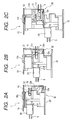
- FIGS. 2A through 2C are side cross-sectional views showing a connector construction example according to the first embodiment and an operating state of the connector, wherein FIG. 2A shows a state in which a first connector mounted on a first mount and a second connector mounted on a second mount are coupled when they are caused to approach each other, FIG. 2B shows a state in which an end face of the terminal engagement member starts moving toward a press protuberance of a holder, and FIG. 2C shows a state in which the end face of the terminal engagement member is pressed against the press protuberance of the holder by means of separating the mounts from each other, to thereby push the terminal engagement member to a predetermined position in the housing.
- FIGS. 3A and 3B are side cross-sectional views showing the connector construction according to the first embodiment and its operating state, wherein FIG. 3A shows a state in which the end face of the terminal engagement member remaining in an insufficiently-inserted state is pressed against the press protuberance of the holder, and FIG. 3B shows a state in which the end face of the terminal engagement member is pressed against the press protuberance of the holder, to thereby push the terminal engagement member to a predetermined position in the housing.
- FIGS. 4A through 4C are side cross-sectional views showing an example connector for coupling a first connector to a first mount and the operating state of the connector, wherein FIG. 4A shows a state in which the terminal engagement member couples a first connector remaining in an insufficiently-inserted state to a first mount, FIG. 4B shows a state in which a first mount is slid, inserted into, and caused to approach a mount section of the first connector, to thereby press a tapered tip-end section of the press protuberance against a tapered section of the terminal engagement member, and FIG. 4C shows a state in which a terminal engagement member is pressed to a predetermined position in the housing a first connector by means of a press protuberance of the first mount.
- FIGS. 5A and 5B are connectors of an overhead module according to the present invention, wherein FIG. 5A is a perspective view, and FIG. 5B is a fragmentary perspective view showing insert shoes.
- FIG. 6 is a perspective cutaway view of the connector shown in FIGS. 5A and 5B , showing insert shoes and a U-shaped spring section.
- FIG. 7 is a perspective view showing a support base.
- FIG. 8 is a cutaway perspective view showing a connector supported by a support base.
- FIGS. 9A and 9B show connectors, wherein FIG. 9A is a cross-sectional plan view of a connector, and FIG. 9B is a cross-sectional side view showing a connector before the connector is supported by a support base.
- FIG. 10 is a side cross-sectional view shoving a connector after the connector has bee supported by the support base.
- FIG. 11 is a fragmentary perspective view showing a modification of the connector when the connector is supported by the support base.
- FIG. 12 is an exploded side view showing a connector construction according to a first embodiment of the present invention. -
- FIGS. 13A and 13B show the connector construction according to the present invention, wherein FIG. 13A is a perspective view showing the assembly of a male connector and a stationary base, and FIG. 13B is an exploded perspective view showing the same.
- FIGS. 14A and 14B are illustrations (perspective views) showing processes of attaching a female holder to a mount of the connector construction according to the first embodiment.
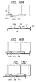
- FIGS. 15A through 15c are illustrations (front cross-sectional views) showing processes for engaging the lock section in a lock hole of the connector construction according to the first embodiment.
- FIG. 16 is a perspective appearance showing a female connector of the connector construction of the first embodiment.
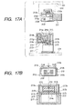
- FIGS. 17A and 17B are illustrations showing connection between connector constructions according to the first embodiment, wherein FIG. 17A is a cross-sectional view showing connectors before coupling, and FIG. 17B is a front cross-sectional view showing the connectors after coupling.
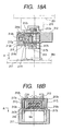
- FIGS. 18A and 18B are illustrations showing connection between connector constructions according to the first embodiment, wherein FIG. 18A is a cross-sectional view showing a temporarily-engaged female connector, and FIG. 18B a front cross-sectional view showing the same.
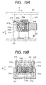
- FIGS. 19A and 19B are illustrations showing connection between connector constructions according to the first embodiment, wherein FIG. 19A is a cross-sectional view showing connectors which are in the process of being coupled, and FIG. 19B a front cross-sectional view showing the same.
- FIG. 20 is a cross-sectional view showing connectors which have been coupled.
- FIGS. 21A through 21C show a hold guide structure of the connector construction according to the first embodiment, wherein FIG. 21A is an exploded cross-sectional view showing connectors before they are held and guided; and FIGS. 21B and 21C are cross-sectional views showing the connectors which are in the course of being held and guided.
- FIG. 22 is an exploded perspective view showing a mount and a female holder according to a second embodiment of the present invention.
- FIG. 23A is a front cross-sectional view showing a female holder before the holder is attached to the mount according to the second embodiment (taken along line J-J shown in FIG. 23B ).
- FIG. 23B is a bottom view showing the female holder.
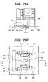
- FIG. 24A is a front cross-sectional view showing a state in which a female holder is slid relative to a mount according to the second embodiment (taken along line K-K shown in FIG. 24B ).
- FIG. 24B is a bottom view showing the same.
- FIG. 25A is a front cross-sectional view showing a female holder which is attached.to a mount according to the present embodiment (taken along line L-L shown in FIG. 25B );
- FIG. 25B is a bottom view.
- FIGS. 26A and 26B show known connectors, wherein FIG. 26A is a perspective view showing assembly of a connector and a support base, and FIG. 26B is an exploded perspective view showing the connector shown in FIG. 26A .
- FIG. 27A is a perspective view showing assembly of a connector and a holder.
- FIG. 27B is an exploded perspective view of the same shown in FIG. 27A .
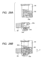
- FIGS. Figs. 28A and 28B show connection of connectors, wherein FIG. 28A is a cross-sectional view showing the connectors before connection, and FIG. 28B is a cross-sectional view showing a temporarily-engaged connector.
- FIGS. 29A and 29B show connection of connectors, wherein FIG. 29A is a cross-sectional view showing connectors which are in the course of being coupled, and FIG. 29B is a cross-sectional view showing connectors after coupling.
- FIGS. 1A through 4C show an example connector construction according to a first embodiment of the present invention.
- a connector 1 is to electrically connect an electrical-component module, such as an automobile instrument module, a door module, or an overhead module, to a panel 13 of a car body, such as a dashboard, a door panel, or a roof panel.
- an electrical-component module such as an automobile instrument module, a door module, or an overhead module
- a first connector 20 is mounted on a first mount 22, and a second connector 10 is mounted on a second mount 13.
- the first connector 20 and the second connector 10 are coupled together by means of causing the first and second mounts 22 and 13 to approach each other. More specifically, the first connector 20 is mounted on the first mount 22 in a laterally-oriented position, and a holder 12 is fixed on the second mount 13 by means of an engagement section 12c.
- the second connector 10 is supported by the holder 12 in a laterally-oriented position so as to be able to deflect in a forward direction. As shown in FIGS.
- the second connector 10 when the first and second mount members 22 and 13 are caused to approach each other, the second connector 10 is connected to the first connector 20 while being oriented laterally and deflected in a forward direction.
- the first connector 20 corresponds to a male connector
- the second connector 10 corresponds to a female connector.
- the present invention is not limited to such an example.
- the first connector 20 may correspond to a female connector
- the second connector 10 may correspond to a male connector.
- a guide pin 11b of the second connector 10 is engagingly supported by a cam slot 12b of the holder 12 in such a way that the guide pin 11b is oriented laterally and movable in a forward direction.
- FIG. 2B when the first and second mounts 22 and 13 are caused to approach each other, the second connector 10 is moved forward while remaining laterally oriented by means of the cam slot 12b.
- FIG. 12A terminals of the first connector 20 and terminals of the second connector 10 are completely engaged with each other.
- an electrode terminal 3 connected to an electric cable 4 by means of crimping is housed in a cavity 11c of the second connector 10.
- the electrode terminal 3 is locked in a position which is in communication with a male terminal insert hole 11a of the housing 11, by means of a lock piece 2a of the terminal engagement member 2 inserted into the housing 11 from a lower surface S1.
- the connector 1 according to the present invention is provided with an insufficient-insertion prevention structure 30.
- the insufficient insertion prevention structure 30 is provided with a press projection 12a for pressing the terminal engagement member 2 into the space defined by the interior walls of the holder 12.
- a press projection 12a for pressing the terminal engagement member 2 into the space defined by the interior walls of the holder 12.
- the connector can prevent insufficient insertion of the terminal engagement member 2 for locking the electrode terminal 3, thereby enabling the terminal engagement member 2 to lock the electrode terminal 3 without fail.
- FIGS. 4A through 4C show an example construction of a connector 6 according to a second embodiment of the present invention.
- a first connector 40 is attached to a mount 41, and a first mount member 51 is attached to an electrical-component module unit case 52.
- guide ribs formed in the first mount member 51 are guided by and slid into guide grooves formed in the mount 41, wherewith the mount 41 is connected to the first mount member 51.
- An electrode terminal (not shown) to be connected to an electric cable 43 is housed in a housing of the first connector 40.
- the electrode terminal is locked in a housing, by means of a terminal engagement member 42 for inserting the electrode terminal from one side of the housing of the first connector 40.
- the first mount member 51 is provided with a push protuberance 51a for pushing the terminal engagement member 42.
- the connector 6 is equipped with an insufficient-insertion prevention structure 60.
- the terminal engagement member 42 remaining in an insufficiently-inserted state is pushed to a predetermined position in the housing of the first connector 40, by means of the push protuberance 51a of the first mount member 51.
- the first mount member 51 is slid and inserted into the mount 41 of the first'connector 40.
- a tapered tip end 51b of the push protuberance 51 comes into contact with a tapered section 42a of the terminal engagement member 42.
- the terminal engagement member 42 is raised by the tapered tip end 51b of the push protuberance 51a.
- the insufficient insertion prevention structure 60 can prevent the terminal engagement member 42 for locking an electrode terminal from being insufficiently inserted.
- the terminal engagement member 42 can lock an electrode terminal in the housing of the first connector 40 without fail.
- the connector according to the present invention is not limited to specific constructions described in connection with the embodiments. Needless to say, the connector construction is susceptible to modification, addition, or deletion, as required.
- the first embodiment illustrates an example in which the insufficient insertion prevention structure 30 of the connector 1 is configured in such a manner that, when the first and second mounts 22 and 13 are separated from each other, the terminal engagement member 2 is pushed to a predetermined position in the housing 11 of the second connector 10 by means of the press protuberance 12a of the holder 12.
- the present invention is not limited to such an embodiment.
- the insufficient insertion prevention structure 30 may be configured in such a way as to act when the first and second mounts 22 and 13 are caused to approach each other.
- both the first connector 20 and the second connector 10 can prevent the terminal engagement member 2 from entering an insufficiently-inserted state.
- FIGS. 5 through 10 show a third embodiment in which a connector (a first connector) 114 of an overhead module (a first mount member; that is, a panel of an electrical module) 103 is connected to a connector 102 (a first connector) of a roof panel (a second mount member; that is, a panel of a car body) 101.
- a support base 115 is mounted on the top of the overhead module 103. As shown in FIG. 7 , an insert shoe groove 115a is formed in an upper portion on either side of the support base 115.
- a square lock section 115b is integrally formed in an upper portion of the support base 115 so as to straddle the insert shoe grooves 115a.
- a lock hole 115c is formed in the center of the lock section 115 so as to penetrate through the support base 115. Further, a square recess 115d is formed in the top surface of the lock section 115a of the support base 115.
- an insert shoe 114a which can be inserted into the insert shoe groove 115a of the support base 115 is formed on either side of the lower surface of a plastic connector 114.
- a spring section 114c which has a U-shape when viewed from the top is integrally formed with a lower portion of the connector 114 between the insert shoes 114a. Respective ends 114b of the spring section 114c are attached to the connector 114. Since only the respective ends 114b of the U-shaped spring section 114c are connected to the connector 114, the other portions of the connector 114 are movable. Therefore, the U-shaped spring section 114c can be moved in any of the vertical, horizontal, and back/forth directions while the ends 114b are taken as fulcrums.
- a lock piece section 114d is integrally formed in the middle of the U-shaped spring section 114c so as to protrude in an opening of the U-shaped spring section 114c.
- a lock claw 114e is integrally formed in the upper surface of the lock piece section 114d so as to protrude upward.
- a displacement regulation projection 114g is integrally formed on a lower surface 114f of the connector 114 opposite the lock claw 114e.
- the insert shoes 114a of the connector 114 are inserted into the corresponding inset shoe grooves 115a of the support base 115 from the state shown in FIG. 9B , as indicated by arrow C.
- the lock section 115b is inserted into a clearance between the upper surface of the lock piece section 114d of the U-shaped spring section 114c of the connector 114 and the lower surface 114f of the connector 114.
- the lock claw 114e of the lock piece section 114d is engaged from below with the lock hole 115c of the lock section 115b of the support base 115.
- the connector 114 is supported by the support base 115 while being oriented laterally.
- the displacement regulation projection 114g is loosely engaged from above with the recess 115d of the lock section 115b.
- the support base 115 supports the first connector 114.
- the lock piece section 114d formed in the middle of the U-shaped spring section 114c of the connector 114 is supported by the lock section 115b of the support base 115. Therefore, the connector 114 is supported so as to be movable in any of the vertical, horizontal, and back/forth directions while the ends 114b are taken as fulcrums.
- the connector 114 since the connector 114 has a self-alignment function which enables displacement with respect to the connector 102 in any of the vertical, horizontal, and back/forth direction, the connector 114 of the overhead module 103 can be smoothly connected to the connector 2 of the roof panel 101.
- the connector 114 can be quickly connected to the support base 115 with a single operation.
- the U-shaped spring section 114c may be extended and broken. Even in such a case, the regulation projection 114g of the connector 114 is brought into contact with the interior wall surfaces of the recess 115d of the lock section 115b of the support base 115, thereby regulating displacement of the connector 114. Therefore, there can be prevented fracture of the U-shaped spring section 114c, which would otherwise be caused when the U-shaped spring section 114c is extended undesirably.
- the regulation projection 114g formed on the lower surface 114f of the connector 114 is loosely engaged with.the recess 115d of the lock section 115b of the support base 115.
- a recess 114h may be formed on the lower surface 114f of the connector 114, and the regulation projection 114g may be formed on the upper surface of the lock piece 114d of the connector 114 such that the regulation projection 114g is loosely engaged from below with the recess 114h.
- the regulation projection 114g is brought into contact with the interior wall surfaces of the recess 114h, thereby regulating displacement of the connector 114.
- the overhead module 103 is mounted on the roof panel 101.
- the present invention is not limited to such an embodiment. Needless to say, the present invention can be applied to an instrument panel, a door module, a center cluster module, or the like.
- FIG. 12 shows a fourth embodiment in which a male connector (first connector) 212 of an overhead module (first mount member, that is, a panel of an electrical component) 201 is coupled to a female connector (second connector) 214 of a roof panel (second mount member; that, is a panel of a car body) 203.
- first connector first connector
- second connector female connector
- roof panel second mount member; that, is a panel of a car body
- a stationary base 215 having an insert shoe groove 215a formed therein is attached to an interior surface 201a of the overhead module 201, and a shoe 212a formed at the bottom of the male connector 212 is inserted into the stationary base 215.
- An engagement' projection 212j of the male connector 212 is engaged with an engagement hole 215b, wherewith the male connector 212 is fixed on the stationary base 215 while being oriented in a lateral direction.
- a narrow clearance is left between the shoe groove 215a of the stationary base 215 and the shoe 212a of the male connector 212 in the forward/backward and right/left directions.
- the male connector 212 is secured on the stationary base 215 so as to be able to oscillate.
- a temporary-engagement release protuberance 212c is formed on the exterior surface on either side of a fitting section 212b of the male connector 212. Further, a hold guide protuberance 212d is formed on the interior surface on either side of the fitting section 212b of the male connector 212. In combination with the hold guide protuberance 212d, an interior upper surface 212e of the fitting section 212b constitutes a hold guide section.
- a cutout 212f is formed in a lower surface of the fitting section 212b of the male connector 212.
- a fitting section 214a of the female connector 214 which will be described later, is fitted into the cutout 212f from below.
- a clearance groove 212g is formed in respective side surfaces of the fitting section 212b for receiving a guide pin 214b, which will be described later.
- a mount 204 which constitutes a part of the roof panel 203 is fastened to the interior surface of the roof panel 203.
- a pair of engagement sections for example, hooks 205, are formed in the mount 204.
- Each of the hooks 205 comprises a raised portion 205a and a horizontal section 205b.
- a lock hole 206 is formed between the hooks 205.
- the lock hole 206 may be either a through hole or recessed.
- a female holder 217 assuming a square box shape has an open top surface, and an opening is formed in each of front and back surfaces.
- a pair of hook insert holes 217b, a pair of hook engagement sections 217c, and a lock section 217d are formed in the bottom surface 217a of the female holder 217.
- the hook 205 is inserted into the hook engagement section 217c by way of the hook insert hole 217b, and the female holder 217 is slid in a forward direction (designated by arrow G).
- the horizontal section 205b of the hook 205 is engaged with the hook engagement section 217c.
- a groove (not shown) into which the raised section 205a is to be inserted is formed in the area of the hook engagement section 217c, which area is close to the hook engagement section 217c.
- the hook engagement section 217c has a groove which is in communication with the hook insert hole 217b.
- the lock section 217d is formed into a tongue shape; specifically, respective sides of the lock section 217d and the longitudinal end opposite the forward direction (designated by arrow G) are cut. Further, a protuberance 217e protrudes from the lock section 217d in a downward direction in FIG. 15A .
- the lock section 217d is engaged with the lock hole 206.
- FIGS. 15A through 15c show a change in the state of the lock section 217d.
- the hooks 205 shown in FIG. 15A are inserted into the hook insert holes 217b, as shown in FIG. 15B . Since the protuberance 217e of the lock section 217d is not situated in a position where the lock hole 206 is present, the protuberance 217e is not engaged with the lock hole 206. Subsequently, the female holder 217 is slid in a forward direction (designated by arrow G), wherewith the protuberance 217e is engaged with the lock hole 206, as shown in FIG. 15C . In the event of an attempt being made to attach the female holder 217 in an orientation differing from that shown in FIGS. 14A through 14C , detection means 207, which protrudes upward in FIGS.
- distance L1 from the hooks 205 to the detection means 207 is shorter than distance L2 from the hook insert holes 217b to the end of the bottom surface 217a of the female holder 217 opposite a forward direction (designated by arrow G). Accordingly, the hooks 205 are not inserted into the hook insert holes 217b, whereby an operator becomes aware that he is attempting to attach the female holder 217 in an incorrect orientation. Upon being aware that he is attempting to attach the female holder 217 in an incorrect orientation, the operator attempts to disengage and attach the female holder 217 in a correct orientation. As shown in FIG.
- lock release means 218 having a recess 218a is formed in the tip end of the lock section 217d.
- a pulling tool (not shown) whose tip end is formed into a hook is engaged with the recess 218a of the lock release means 218.
- the lock release means 218 is pulled upward, to thereby release the protuberance 217e from the lock hole 206.
- the lock release means 218 may be embodied by means of causing a portion of the surrounding area of the lock hole 206 of the mount 204 shown in FIG. 15A to extend to a location below the protuberance 217e, and the thus-extended portion may be pulled upward through use of a similar pulling tool.
- the guide pin 214b protrudes sideward from respective exterior side surfaces of the fitting section 214a of the female connector 214.
- a cam slot 217f tapered down in the direction opposite the forward direction (designated by arrow G) is formed in respective side section 217e' of the female holder 217.
- An upper portion 217g of the cam slot 217f is tapered slightly downwardly.
- the guide pin 214b of the female connector 214 is fitted into the cam slot 217f.
- the fitting section 214a of the female connector 214 is coupled to the fitting section 212b of the male connector 212 which is secured stationary and oriented in a lateral direction.
- An upper engagement protuberance 217h and a lower temporary engagement protuberance 217i are formed on the interior surface of respective side 217e' of the female holder 217. While the guide pins 214b of the female connector 214 are engaged with upper portions 217g of cam slots 217f, a lower flange 214c of the female connector 214 is caught between the upper engagement protuberance 217h and the temporary engagement protuberance 217i. As a result, the female connector 214 is temporarily engaged in an initial lateral position (see FIGS. 17A and 17B ).
- An engagement groove 217j is formed in a position on the interior surface of respective side 217e' of the female holder 217, the position being close to a front opening.
- the temporary engagement release protuberance 212c of the male connector 212 is fitted into the engagement groove 217j.
- a temporary engagement release protuberance 217k is formed in a position on the bottom between the engagement protuberance 217h of the engagement groove 217j and the temporary engagement protuberance 217i.
- a guide rail section 214d is formed on the exterior surface of respective side of the engagement section 214a of the female connector 214.
- the male connector 212 is laterally fixed on the stationary base 215 of the overhead module 201 before coupling (assembly).
- the female connector 214 of the roof panel 203 is temporarily and laterally engaged with the female holder 217 in an initial position. More specifically, while the guide pin 214b of the female connector 214 is engaged with the upper portion 217g of the cam slot 217f of the female holder 217, the lower flange 214c of the female connector 214 is locked in a position between the engagement protuberance 217h and the temporary engagement protuberance 217i.
- the overhead module 201 approaches in parallel with the roof panel 203 (in the direction designated by arrow A), the temporary engagement release protuberance 212c of the male connector 212 fits into the engagement groove 217j of the female holder 217, and the cutout 212f of the engagement section 212b of the male connector 212 is engaged with the engagement section 214a of the female connector 214.
- terminals provided in the engagement section 212b and terminals provided in the engagement section 214a are in a state immediately preceding an engaged state.
- the temporary engagement release protuberance 212c of the male connector 212 sits astride and runs on the temporary engagement release protuberance 217k of the engagement groove 217j of the female holder 217, thereby pressing the temporary engagement release protuberance 217k outward.
- the sides 217e' are bulged outward from the state designated by broken lines to the state designated by solid lines.
- the temporary engagement protuberance 217i is moved outward, thereby releasing the lower flange 214c of the female connector 214 from a temporarily-engaged state or bringing the lower flange 214c into a nearly-released state.
- the hold guide protuberance 212d of the engagement section 212b of the male connector 212 sits astride and runs on the hold guide rail 214d of the engagement section 214a of the male connector 214. Finally, the hold guide protuberance 212d is engaged with the lower end of the hold guide rail 214d.
- the male connector 212 is sustained (or locked) by the female connector 214 so as not to move in an engagement direction (in the direction in which the male connector 212 is to be engaged with the female connector 214).
- the inner upper surface 212e of the engagement section 212b of the male connector 212 remains in contact with the upper surface 212e of the engagement section 214a of the female connector 214 (see FIGS. 19A and 19B ).
- the guide pins 214b of the female connector 214 are moved laterally in a forward direction F while being guided by the cam slots 217g and 217f of the female holder 217.
- the engagement section 212b of the male connector 212 is engaged with the engagement section 214a of the female connector 214, wherewith terminals of the engagement section 214a of the female connector 214 are engaged with terminals of the engagement section 212 of the male connector 212.
- the hold guide protuberance 212d of the engagement section 212b of the male connector 212 is engaged with the lower end of the hold guide rail 214d of the engagement section 214a.
- lateral movement of the female connector 214 in forward direction F is allowed, and the inner upper surface 212e of the engagement section 212b of the male connector 212 is in contact with the upper surface 214e of the engagement section 214a of the female connector 214.
- the lateral movement of the female connector 214 in forward direction F is guided by the hold guide protuberance 212d and the inner upper surface 212e of the male connector 212 until the male connector 212 is completely coupled with the female connector 214.
- the female connector 214 is further moved laterally in forward direction F.
- the engagement section 212b of the male connector 212 is deeply engaged with the engagement section 214a of the female'connector 214.
- Terminals of the engagement section 214a of the female connector 214 are completely coupled with terminals of the engagement section 212b of the male connector 212. Connection of the male connector 212 to the female connector 214 is now completed.
- the engagement section 214a of the female connector 214 is connected to the engagement section 212b of the male connector 212 while being moved laterally in forward direction F.
- connection of the female connector 214 to the male connector 212 is completed.
- the male connector 212 and the female connector 214 remain in a lateral orientation before and after connection. Therefore, there is obviated a necessity for ensuring a wide connector coupling space between the roof panel 203 and the overhead module 201 (in a depthwise direction). Therefore, even in a case where only a narrow space is ensured in a depthwise direction, connectors can be coupled.
- terminals of the engagement section 212b of the male connector 212 are completely coupled with terminals of the engagement section 214a of the female connector 214 before the male connector 212 is completely connected to the female connector 214. Subsequently, connection of the engagement section 212b of the male connector 212 to the engagement section 214a of the female connector 214 is completed while the engagement section 212b and the engagement section 214a remain in a lateral orientation. Terminals of the engagement section 212b and terminals of the engagement section 214a are completely connected together before connection of the male connector 212 to the female connector 214 is completed.
- the male connector 212 of the overhead module 201 is fixed on the stationary base 215 so as to be able to oscillate. In the event that a certain amount of positional error arises between the male connector 212 of the overhead module 201 and the female connector 214 of the roof panel 203 in terms of assembly, oscillating action of the male connector 212 provides versatility of positional adjustment during assembly. Accordingly, the male connector 212 can be smoothly connected to the female connector 214 without a hitch.
- the female holder 217 At the time of the female holder 217 being connected to the mount 204 of the roof panel 203, the hooks 205 of the mount 204 are inserted into the corresponding hook insert holes 217b of the female holder 217.
- the female holder 217 is slid, wherewith the hooks 205 are engaged with the hook engagement sections 217c.
- the female holder 217 can be attached to the roof panel 203 with a single motion. Accordingly, the ease of assembly of connectors is enhanced. Attachment of the female holder 217 to the mount 204 while the female holder 217 is oriented in an incorrect direction is detected by the detection means 207. Therefore, the female holder 217 is attached to the mount 204 at all times while being oriented in a predetermined direction.
- the female connector 214 having a harness connected thereto may be attached to the female holder 217 mounted on the roof panel 203.
- slack in the harness of the female connector 214 ensured for assembly purpose becomes longer.
- a harness is connected to the female connector 214, and the female connector 214 having the harness attached thereto is connected to the female holder 217.
- the female holder 217 having the female connector 214 connected thereto is fixed on the roof panel 203.
- slack in the harness ensured for assembly purpose becomes shorter, thus resulting in cost reduction.
- the hooks 205 are formed in the mount 204, and the hook insert holes 217b and the hook engagement sections 217c are formed in the female holder 217.
- the present invention may be embodied by employment of configurations shown in FIGS. 22 through 25B . More specifically, hook insert holes 221 and hook engagement sections 222 may be formed in a mount 220, and hooks 231 may be formed in a female holder 230.
- the detection means 207 is formed in the mount 204 so as to protrude upward toward the female holder 217.
- the present invention may be embodied preferably in the configurations shown in FIGS. 22 through 25B . More specifically, detection means 233 is preferably formed in the female holder 230 so as to protrude downward toward the mount 220.
- the female holder 230 has a square box shape, and the top of the female holder 230 is open. An opening is formed in the front and back surfaces of the female holder 230.
- a pair of hooks 231 serving as engagement sections are formed in a bottom surface 230a of the female holder 230.
- Each hook 231 has a raised section 231a and a horizontal section 231b.
- the raised section 231a has an L-shaped geometry. A shorter portion of the raised section 231a extends outward in the direction orthogonal to a direction designated by arrow H (hereinafter referred to as a "direction H"), and a longitudinal portion of the raised section 231a extends in the direction opposite the direction H.
- the end of the raised section 231a in the direction H projects from the end of the horizontal section 231b in the direction H, to thereby constitute a projection 231c.
- the projection 231c of the raised section 231a has the function of preventing attachment of the female holder 230 while the female holder 230 is directed in an incorrect orientation.
- the end of the L-shaped raised section 231a opposite the direction H acts as a stopper.
- a lock section 232 is formed in the area between the pair of hooks 231. As shown in FIGS. 23 through 25B , the lock section 232 has a protuberance 232a formed in the shape of a tongue. Specifically, the longitudinal sides of the protuberance 232a are cut, and the longitudinal end 232a in the direction opposite the direction H is also cut. The protuberance 232a has a downwardly-protruding bulge.
- Detection means 233 for detecting attachment of the female holder 230 while the female holder 230 is directed in an incorrect orientation is provided at the end on the bottom of the female holder 230 in the direction opposite the direction H.
- the detection means 233 is formed so as to protrude downward.
- the mount 220 which constitutes a part of the roof panel 203 (not shown) is mounted on the interior surface (i.e., shown in a lower portion of the drawing) by way of an unillustrated support member while a narrow clearance is ensured between the roof panel 203 and the mount 220.
- a pair of hook insert holes 21 are formed in the mount 220, and hook engagement sections 222 are formed in the mount 220 so as to communicate with the respective hook insert holes 221.
- a lock hole 223 for locking the projection 232a is formed in the mount 220.
- a receiving hole 224 is also formed in the mount 220 next to the lock hole 223 in the direction opposite the direction H.
- an opening hole 225 into which the detection means 233 is to be inserted is formed in the mount 220.
- the hook insert hole 221 is formed so become slightly larger than the horizontal section 231b, so that the horizontal section 231b of the hook 231 can readily enter the hook insert hole 221.
- the female holder 230 is caused to approach the mount 220, and the hooks 231 are inserted into the hook insert holes 221.
- the female holder 230 can be attached to the mount 220 in only a direction in which the detection means 22 is inserted into the opening hole 225.
- the projection 231c of the hook 231 is inserted into the groove of the hook engagement section 222.
- insertion of the projection 231c of the hook 231 is blocked by the hook insert hole 221.
- the projection 231c also contributes to prevention of attachment of the female holder 230 while the female holder 230 is directed in an incorrect orientation. As a result of insertion of the projection 231c being blocked, the operator becomes aware that he is attempting to attach the female holder 230 in an incorrect orientation. Therefore, the operator will attach the female holder 230 by means of changing the orientation of the female holder 230.
- the wide portion of the opening hole 225 is intended for facilitating insertion of the detection means 233 into the opening hole 225. Further, a narrow portion of the opening hole 225 is formed so that the sides 225b of the opening hole 225 can guide the detection means 233 to a predetermined position at the time of sliding of the female holder 230, which will be described later.
- the female holder 230 After having been set in a pre-mounting state, the female holder 230 is slid in the direction H (forward direction), as shown in FIGS. 24A and 24B . As a result, the raised section 231a passes through the groove of the hook engagement section 222, and the protuberance 232a of the lock'section 232 sits on and runs on the area between the receiving hole 224 and the lock hole 223. As shown in FIGS. 25A and 25B , the horizontal section 231b of the hook 231 is engaged with the hook engagement section 222, and the protuberance 232a is inserted into and locked by the lock hole 223.
- the female holder 230 is attached to the mount 220.
- the receiving hole 224 and the lock hole 223 are not limited to through holes but may be recessed.
- distance L3 between the end face 225a and the lock hole 223 is set to become shorter than distance L4 between the detection means 233 and the protuberance 232a. Even in a state in which the protuberance 232a is locked in the lock hole 223, the female holder 230 can move in the direction H relative to the mount 220 over only a distance corresponding to the distance between L3 and L4. In other words, the female holder 230 has play relative to the mount 220.
- a pulling tool (not shown) whose tip end is formed into a hook is engaged with a recess 232b (lock release means) formed in the end of the lock section 232.
- the recess 232b is pulled upward, to thereby release the protuberance 232a from the lock hole 223.
- the lock release means 232b may be embodied by means of causing a portion of the surrounding area of the lock hole 223 of the mount 220 to extend to a location below the protuberance 232a, and the thus-extended portion may be pulled upward through use of a similar pulling tool.
- engagement-receiving sections each comprising a hook insert hole and a hook engagement section
- a holder has engagement sections and accordingly has a complicated constitution. Since the holder is usually formed by means of molding through use of molds, the only requirement is modification of the design of molds, which does not pose any problem in manufacture of a holder. A holder manufactured through use of molds is usually provided with detection means for detecting attachment of the holder while the holder is directed in an incorrect orientation. Therefore, even in the case of a holder construction being complicated, the only requirement is modification of the design of molds, which does not pose any problem in manufacture of a holder. When a hole for receiving projecting detection means is formed in the second mount, the hole can be embodied by means of drilling the second mount, which does not involve any difficulty in machining.
- hooks are provided as engagement sections, and hook insert holes and hook engagement sections are provided as engagement-receiving sections.
- the present invention is not limited to such a connector construction; any connector construction can be employed, so long as the construction enables engagement of connectors by means of sliding action.
- the embodiment are directed toward attachment of the overhead module 201 (such as a lamp) to the roof panel 203, but the present invention is not limited to these embodiments. Needless to say, the present invention can be applied to a door module or a center cluster module.
- the present invention provides the connector comprising:
- the present invention can be applied to a connector which couples a second connector to a first connector while being directed laterally and deflecting in a forward direction. Therefore, there is achieved the same working-effect as that mentioned previously.
- the present invention can be applied to a connector which connects a first, connector to a first mount.
- the insufficient insertion prevention structure pushes a terminal engagement member in an insufficiently-inserted state to a predetermined position in the housing of the first connector. Accordingly, there is achieved the same working-effect as that mentioned previously.
- a lock section of a support base is inserted into a clearance between a lower surface of a first connector and an upper surface of a lock piece section, wherewith a lock claw of the lock piece section is engaged with a lock hole formed in the lock section.
- a first connector is supported by the support base, and the lock piece section provided in the middle of a U-shaped spring is supported by the lock section of the support base. Accordingly, the first connector is supported so as to be able to deflect in any of the vertical, horizontal, and back/forch directions while both ends of the U-shaped spring are taken as fulcrums.
- the first connector When the first and second connectors are engaged with each other, the first connector has a self-alignment function of deflecting with respect to the second connector in any of the vertical, horizontal, and back/forth directions. Therefore, the first connector can be readily engaged with the second connectors.
- the connector is configured such that the lock claw of the lock piece section of the first connector is engaged from below with the lock hole of the lock section of the support base when shoes of the first connector are inserted into shoe grooves formed in the support base.
- the first connector can be quickly supported by the support base with a single operation.
- the regulation projection of the first connector is loosely engaged with the lock hole of the lock section of the support base, wherewith displacement of the first connector is regulated. If an operator erroneously and forcefully pulls electric wires of the first connector, the U-shaped spring section may be extended and broken. However, the regulation projection of the first connector is brought into contact with the interior wall surfaces of the recess, wherewith displacement of the first connector is regulated. Thus, there is prevented fracture of the U-shaped spring section, which would otherwise be caused when the same is extended undesirably.
- the connector construction according to the present invention when a holder is slid in the longitudinal direction of a second mount member, engagement sections are engaged with engagement-receiving sections. Further, a lock section is engaged with a lock-receiving section.
- a first connector is mounted on a first mount member while being directed in a lateral orientation.
- a holder of the second mount member supports a second connector laterally so that the second connector can oscillate in a forward direction.
- the second connector is connected to the first connector while being oriented laterally and oscillating in a forward direction.
- first and second connectors remain oriented laterally before and after connection, there is obviated a necessity for ensuring a wide connector coupling space between connectors (in the depthwise direction thereof). Accordingly, connectors can be coupled even in the case of only a narrow space being ensured in a depthwise direction of connectors.
- a harness is connected to the second connector, and the second connector having the harness attached thereto is attached to a holder.
- the holder having the second connector attached thereto is mounted on the second mount member.
- slack in the harness can be shortened, which in turn results in cost reduction.
- occurrence of unusual noise which would otherwise be caused by slack, can be eliminated, and a possibility that electric wires could be caught during assembly of panels can be reduced.
- Engagement sections each comprising a hook
- engagement-receiving sections each comprising a hook insert hole and a hook engagement section
- the engagement-receiving sections can be formed in the second mount member by means of drilling the second mount member. Further, a holder which is usually formed through use of molds can be produced through mere modification of the design of molds, thus posing no problem in manufacture of a holder.
- the presence of the projection blocks insertion of the hook into a hook insert hole even when an attempt is made to insert the hook in the hook insert hole while the hook is directed in an incorrect orientation. Therefore, the projection can prevent attachment of the holder while the holder is directed in an incorrect orientation.
- the holder can be readily disengaged from the second mount member.
- the connector construction is provided with detection means for detecting attachment of a holder while the holder is directed in an incorrect orientation, the holder can be attached to the second mount member in a given direction.
- the detection means is convenient in a case where an engagement section is engaged with an engagement-receiving section in a specific orientation.
- the detection means is formed in the holder so as to protrude toward the second mount member.
- a holder usually formed through use of molds is provided with the detection means. Therefore, even in a case where the structure of the holder becomes complicated, the only requirement is modification of the design of molds, thus posing no problem in manufacture of a holder.
- an opening hole for receiving projecting detection means is formed in the second mount member, and can be made by means of only drilling the second mount member, thus involving no problems in the ease of machining.
- the present invention obviates a necessity of manual connection of connectors during assembly processes of an automobile. Therefore, occurrence of unusual noise, which would otherwise be caused by slack, can be prevented, and a possibility that electric wires could be caught during assembly of panels is reduced. Hence, various countermeasures, which have conventionally been taken for preventing such problems, can be obviated. Further, since connectors can be connected even when only a narrow depthwise space is ensured between a panel of a car body and a panel of an electrical module, the interior room of a car can be increased correspondingly.
Landscapes
- Details Of Connecting Devices For Male And Female Coupling (AREA)
- Coupling Device And Connection With Printed Circuit (AREA)
Abstract
Description
- The present invention relates to a connector used for electrically connecting various electrical-component modules to a panel of a car body.
- During conventional processes for assembling a meter panel, a door module, an overhead module, or the like, after connectors of a wire harness of a panel of a car body (for example, a dashboard, a door panel, or a roof panel) have been manually coupled to connectors of a wire harness of a panel of an electrical-component module (for example, an instrument panel or an inner panel), a panel of an electrical-component module is attached to the panel of the car body. A necessity for manual coupling of connectors imposes a problem in terms of the ease of assembly. Further, a wire harness of connectors requires slack, and slack in the wire harness may cause unusual noise and raises a possibility that electric wires could be caught during assembly of panels. Preventing such problems has required various countermeasures.
- To this end, there have been proposed connectors which can be coupled together simultaneous with attachment of an electrical module to a stationary panel of a car body (see unexamined Japanese Patent publication No.
Hei. 5-54933 - Moreover, there have been proposed connectors which can be coupled together simultaneous with attachment of an electrical module to a stationary panel of a car body (see unexamined Japanese Patent publication No.
Hei. 10-242040 - According to the Japanese publication No.
10-242040 - Specifically, the connectors are embodied by means of a connector (first connector) 304 of an overhead module (e.g., a room lamp) module 303 (shown in
FIGS. 26A and 26B ) being connected to a connector (second connector) 303 of a roof panel 301 (shown inFIGS. 27A and 27B ). - A
support base 305 is mounted on the upper surface of theoverhead module 303, and aninsert shoe groove 305a is formed in thesupport base 305. Ashoe 304b formed on the bottom of theconnector 304 is inserted into thesupport base 305, and an engagement projection 4c of the connector 4 (seeFIG. 28A ) is engaged with an engagement hole 4b. As a result, theconnector 304 is fixed on top of thesupport base 305 while being oriented laterally. - A square-box-
shaped holder 306 is attached to the lower surface of theroof panel 301. Aguide pin 302b of theconnector 302 is engaged with and guided by acam slot 306a of theholder 6. Anengagement section 302a of theconnector 302 is engaged with anengagement section 304a of thestationary connector 304 while being moved in a forward direction (designated by arrow F) and being oriented laterally. - As shown in
FIG. 28A , theholder 306 of theroof panel 301 temporarily holds theconnector 302 in an initial position while being oriented laterally, and theconnector 304 of theoverhead module 303 is secured laterally. - As shown in
FIG. 28B , when theoverhead module 303 is caused to approach theroof panel 301 in parallel (as designated by arrow A), theengagement section 304a of theconnector 304 is fitted into theengagement section 302a of theconnector 302. - When the
overhead module 303 is caused to approach theroof panel 301 further, theguide pin 302b is guided, as shown inFig.29A , by thecam slot 306a of theholder 306 and is moved in forward direction F while being oriented laterally. In association with approaching of theoverhead module 303 to theroof panel 301, theengagement section 302a of theconnector 302 is engaged with theengagement section 304a of theconnector 304, wherewith terminals of theengagement section 302a of theconnector 302 are connected to terminals of theengagement section 304a of theconnector 304. - As shown in
FIG. 29B , when theoverhead module 303 is caused to approach theroof panel 301 to a further extent, theconnector 302 is moved further in the forward direction F while being oriented laterally. Theengagement section 302a of theconnector 302 is deeply engaged with theengagement section 304a of theconnector 304, wherewith terminals of theconnector 302 and terminals of theconnector 304 are completely connected together. Thus, connection of theconnector 304 to theconnector 302 is completed. - As mentioned above, if the
overhead module 303 is caused to approach theroof panel 301, theengagement section 302a of theconnector 302 is engaged with theengagement section 304a of theconnector 304 while being moved in the forward direction F and being oriented laterally. Therefore, theconnectors roof panel 301 and the overhead module 303 (in a depthwise direction thereof). Theconnectors - In a connector, a terminal engagement member is usually inserted from one side of a housing, and an electrode terminal housed in a cavity is engaged with the housing.
- In a known connector, in the case where a terminal engagement member for engaging an electrode terminal in the housing is inserted to an insufficient extent; in other words, to a predetermined position in the housing, the terminal engagement member fails to engage the electrode terminal in the housing.
- Moreover, if relative vertical and/or horizontal positional displacements arise between the
connectors connector 302 cannot be smoothly engaged with theconnector 304 while theoverhead module 303 is being caused to approach theroof panel 301. For this reason, demand exists for theconnectors - Also, in connection with commercialization, this connector construction has room for improvement in terms of ease of assembly.
- The present invention has been conceived to solve such a problem of the related art and, and an object of the invention is to provide a connector which prevents insufficient insertion of a terminal engagement member for engaging an electrode terminal, thereby engaging the electrode terminal in the housing without fail.
- According to a first aspect of the invention, there is provided a connector comprising:
- a first connector mounted on a first mount, and
- a second connector mounted on a second mount, in which, when the first and second mounts are caused to approach each other, the first connector is connected to the second connector, the connector comprising:
- a holder for sustaining at least one of the first and second connectors;
- a terminal engagement member for locking, in a housing, an electrode terminal which is inserted from one side of the housing of the connector and is to be housed in the connector;
- a press protuberance provided on a holder for pushing the terminal engagement member; and
- an insufficient insertion prevention structure for pushing a terminal engagement member in an insufficiently-inserted state to a predetermined position in a housing of the connector, by means of a press protuberance of the holder when the first and second mounts are caused to move relatively.
- By means of the foregoing connector construction, when the first and second mounts are caused to move relatively, an insufficient insertion prevention structure pushes a terminal engagement member in an insufficiently-inserted state to a predetermined position in a housing of the connector by means of a press protuberance of a holder. Accordingly, the connector can prevent the terminal engagement member for locking an electrode terminal from entering an insufficiently-inserted state. Thus, the electrode terminal can be locked in a housing without fail.
- According to a second aspect of the invention, there is provided a connector comprising:
- a first connector mounted on a first mount,
- a second connector mounted on a second mount, the first connector being connected to the second connector when the first and second mounts are caused to approach each other,
- the first connector being mounted on the first mount in a laterally-oriented position,
- a holder mounted on the second mount, and
- the second connector being supported by the holder in such a manner that the second connector is oriented laterally and can deflect in a forward direction, in which, when the first and second mounts are caused to approach each other, the second connector is connected to the first connector while being oriented laterally and deflected in a forward direction, the connector comprising:
- a terminal engagement member for locking, in a housing, an electrode terminal which is inserted from one side of the housing of the second connector and is to be housed in the second connector;
- a press protuberance provided on a holder for pushing the terminal engagement member; and
- an insufficient insertion prevention structure for pushing a terminal engagement member in an insufficiently-inserted state to a predetermined position in a housing of the second connector by means of a press protuberance of the holder when the first and second mounts are caused to move relatively.
- Further, the present invention can be applied to a connector which couples a second connector to a first connector while being directed laterally and deflecting in a forward direction. Therefore, there is achieved the same working-effect as that mentioned previously.
- According to a third aspect of the invention, there is provided a connector for connecting a first connector to a first mount, comprising:
- a terminal engagement member for locking, in a housing, an electrode terminal which is inserted from one side of the housing of the first connector and is to be housed in the first connector;
- a press protuberance provided on the first mount for pushing the terminal engagement member; and
- an insufficient insertion prevention structure for pushing a terminal engagement member in an insufficiently-inserted state to a predetermined position in a housing of the first connector by means of a press protuberance of the first connector when the first connector and the first mount are caused to move relatively.
- When the first connector and the first mount are caused to approach each other, the insufficient insertion prevention structure pushes a terminal engagement member in an insufficiently-inserted state to a predetermined position in the housing of the first connector. As a result, a terminal engagement member for locking an electrode terminal can be prevented from entering an insufficiently-inserted state, thus locking the electrode terminal in the housing without fail.
- According to a fourth aspect of the invention, there is provided a connector comprising:
- a support base mounted on a first mount member,
- a first connector which is oriented laterally and is supported by the support base so as to be able to deflect in any of the vertical, horizontal, and back/forth directions, a holder mounted on a second mount member, and
- a second connector which is supported by the holder while being oriented laterally and can be deflected in a forward direction, wherein when the first and second mount members are caused to approach each other, the second connector is coupled to the first connector while being deflected in a forward direction and oriented laterally, the connector comprising:
- a lock section which is formed on the support base and has a lock hole formed therein;
- a spring section which is formed in a lower portion of the first connector, is connected at both ends to the first connector, and has a U-shaped shape form when viewed from the top; and
- a lock piece section which has a lock claw and is formed in the middle of the U-shaped spring section, wherein, when the lock section of the support base is inserted into a clearance between the lower surface of the first connector and the upper surface of the lock piece section, the lock claw of the lock piece section is engaged with the lock hole of the lock section, whereby the first connector is supported so as to be able to deflect while both ends of the U-shaped spring section are taken as fulcrums.
- By means of such a connector, the lock section of the support base is inserted into the clearance between"the lower surface of the connector and the upper surface of the lock piece, and the lock claw of the lock piece is engaged from below with the lock hole of the lock section. As a result, the support base supports the first connector.
- At this time, the lock piece section formed in the middle of the U-shaped spring section of the connector is supported by the lock section of the support base. Therefore, the connector is supported so as to be movable in any of the vertical, horizontal, and back/forth directions while the ends are taken as fulcrums.
- Preferably, insert shoe grooves are formed in an upper portion of the support base, and inset shoes are formed in a lower portion of the first connector. When the shoes of the first connector are inserted into the shoe grooves of the support base, the lock claw of the lock piece of the first connector is engaged with the lock hole of the lock section.
- Preferably, A recess is formed in the upper surface of the lock section of the support base, and a regulation projection is formed on the lower surface of the first connector. When the lock claw of the lock piece section of the first connector is engaged from below with the lock hole of the lock section of the support base, the regulation projection is loosely engaged from above with the recess. Further, the regulation projection is brought into contact with the interior wall surfaces of the recess, thereby regulating displacement of the first connector.
- Preferably, a recess is formed in the lower surface of the first connector, and a regulation projection is formed on the upper surface of the lock piece section of the first connector. When the lock claw of the lock piece section of the first connector is engaged from below with the lock hole of the lock section of the support base, the regulation projection is loosely engaged from below with the recess. Further, the regulation projection is brought into contact with the interior wall surfaces of the recess, thereby regulating displacement of the first connector.
- Preferably, the first and second mount members correspond to a stationary panel of a car body and an electrical module. As a result, there is obviated a necessity for manually connecting connectors during the process of assembling an automobile.
- According to a fifth aspect of the invention, there is provided a connector including:
- a first connector mounted on a first mount member while being oriented in a lateral direction,
- a holder mounted on a second mount member disposed opposite the first mount member, and
- a second connector attached to the holder while being oriented in a lateral direction so as to be able to oscillate in a forward direction, wherein, when the first and second mount members are caused to approach each other, the second connector is coupled to the first connector while being oriented in a lateral direction and oscillating in a forward direction, the construction comprising:
- an engagement section provided in the holder' or the second mount member;
- an engagement-receiving section provided in the holder or the second mount member such that the engagement-receiving section can be engaged with the engagement section when the holder is slid in the longitudinal direction of the second mount member;
- a lock section formed in either the holder or the second member; and
- a lock-receiving section formed in the counterpart of the holder or the second member (i.e., the second member of the holder) such that the lock section is engaged with the lock-receiving section when the holder is engaged with the second mount member in such a manner that the lock section can be engaged with the lock-receiving section so as to stop movement of the holder.
- According to a sixth aspect of the invention, when a holder is slid in the longitudinal direction of a second mount member, engagement sections are engaged with engagement-receiving sections. Further, a lock section is engaged with a lock-receiving section. Thus, the holder can be attached to the second mount with a single operation, thus improving the ease of assembly of connectors. Moreover, a first connector is mounted on a first mount member while being directed in a lateral orientation (i.e., in the direction orthogonal to the direction in which the first and second mount members are mutually opposed). A holder of the second mount member supports a second connector laterally so that the second connector can oscillate in a forward direction. When the first and second mount members are caused to approach each other, the second connector is connected to the first connector while being oriented laterally and oscillating in a forward direction.
- Preferably, the engagement section is formed from a hook, and the engagement-receiving section is formed from a hook insert hole and a groove communicating with the hook insert hole.
- According to a seventh aspect of the invention, if the engagement section formed from a hook is slid after having been inserted into the hook insert hole of the engagement-receiving section, the hook is engaged with the hook engagement section of the engagement-receiving section. In this case, the engagement section formed from a hook is formed in the center of either the second mount member of the holder, and the engagement-receiving section, which includes a hook insert hole formed separately from the hook engagement section, is formed in the center of the counterpart. As a result, convenience is afforded. More specifically, in a case where only a hook serving as an engagement section and an engagement-receiving section formed from solely a hook insert hole that is an engagement-receiving section from which the hook insert hole is omitted are formed in respective ends of the second mount member and the holder, the distance over which the hook is to be slid becomes shorter. However, in a case where the engagement section is formed in the center of either the second mount member of the holder and the engagement-receiving section are formed in the center of the counterpart in order to improve the attachment of the holder to the second mount member, the hook engagement section is made long, and the distance over which the hook is to be slid must be made long. Further, limitation is imposed on the degree of freedom of the structure of an area surrounding the region at which the hook is to be slid. In the case of the connector construction in which the engagement-receiving section has a hook insert hole formed separately from the hook engagement section, a hook is inserted into and slid in the hook insert hole, wherewith the hook is readily engaged. Therefore, the ease of operation is improved.
- Preferably, the engagement section formed from the hook is formed in the holder, and the engagement-receiving section comprising the hook insert hole and the hook engagement section is formed in the second mount member.
- Preferably, an engagement-receiving section, which comprises a hook insert hole and a hook engagement section, can be formed in a second mount member by means of forming holes in the second mount member. A holder has an engagement section and accordingly has a complicated constitution. Since the holder is usually formed by means of molding through use of molds, the only requirement is modification of the design of molds, which does not pose any problem in manufacture of a holder. In contrast, the engagement-receiving section is formed in the holder and the engagement section is formed in the second mount member, requiring formation of holes of different types in the second mount member and bending the second mount member. Strict dimensional accuracy is required, and achievement of machining accuracy is difficult, thus adding to manufacturing costs.
- Preferably, a protuberance is formed in the hook such that that the protuberance reaches the groove of the hook engagement section while the hook is inserted into the hook insert hole and such that insertion of the hook into the hook insert hole is blocked when the hook is inserted into the hook insert hole while being oriented in an incorrect direction.
- By means of employment of such a construction, if an attempt is made to insert a hook into a hook insert hole while the hook is oriented in an incorrect direction, the protuberance formed in the hook blocks insertion of the hook into the hook insert hole, thus preventing insertion of a hook while the hook is oriented in an incorrect direction.
- Preferably, lock release means for releasing the holder from a stopped state is formed in at least either the lock section or the lock-receiving section.
- When the lock release means is activated to thereby disengage the lock section from the lock-receiving section; that is, to thereby release the lock section from a locked state, suspension of relative movement between the second mount member and the holder is released, wherewith the second mount member is separated from the holder.
- Preferably, detection means for detecting whether or not the holder is attached to the second mount member while being oriented in a specified direction is formed in at least either the second mount member or the holder.
- By means of employment of such a construction, if an attempt is made to attach the holder to the second mount member while the second mount member is oriented in an incorrect direction, the detection means makes an operator aware of the holder being oriented in an incorrect direction. As a result, the operator can attach the holder to the second mount member in only a predetermined direction. In a case where the engagement section is engaged with the engagement-receiving section while the engagement section is oriented in a specified direction, such detection means is effective.
- Preferably, the detection means is formed on the holder so as to protrude toward the second mount member.
- A holder usually formed through use of molds is provided with the detection means. Therefore, even in a case where the structure of the holder becomes complicated, the only requirement is modification of the design of molds, thus posing no problem in manufacture of a holder. This is particularly effective when the engagement section formed from a hook is formed in the holder and the engagement-receiving section formed from a hook insert hole and a hook engagement section is formed in the second mount member.
- Preferably, an opening hole is formed in the second mount member for receiving the detection means formed in the holder.
- By means of employment of such a construction, unless the detection means is inserted into the opening hole, a hook cannot be inserted into the hook insert hole. Further, in a state in which a.hook is inserted in the hook insert hole, there can be prevented relative rotation between the second mount member and the holder. Moreover, when an opening hole is formed in the second mount member, the hole can be formed by means of drilling the second mount hole, which does not pose any problem in terms of ease of machining. This is particularly effective when the present invention is applied to combination of a construction in which the detection means is formed in the holder so as to protrude toward the second mount member and a construction in which the engagement section formed from a hook is formed in the holder and the engagement-receiving section formed from a hook insert hole and the hook engagement section is formed in the second mount member.
- Preferably, the first and second mount members correspond to a stationary panel of a car body and movable panel of an electrical module.
-
FIGS. 1A through 1D are front cross-sectional views showing a connector construction according to a first embodiment of the present invention and an operating state of the connector, whereinFIG. 1A shows a state in which a terminal engagement member moves a second connector remaining in an insufficiently-inserted state to a push protuberance formed on a holder,FIG. 1B shows a state in which an end face of the terminal engagement member is caused to approach the press protuberance of the holder,FIG. 1C shows a state in which an end face of the terminal engagement member is pressed against the press protuberance of the holder, andFIG. 1D shows a state in which the terminal engagement member is pushed to a predetermined position in the housing of the second connector by means of the press protuberance of the holder. -
FIGS. 2A through 2C are side cross-sectional views showing a connector construction example according to the first embodiment and an operating state of the connector, whereinFIG. 2A shows a state in which a first connector mounted on a first mount and a second connector mounted on a second mount are coupled when they are caused to approach each other,FIG. 2B shows a state in which an end face of the terminal engagement member starts moving toward a press protuberance of a holder, andFIG. 2C shows a state in which the end face of the terminal engagement member is pressed against the press protuberance of the holder by means of separating the mounts from each other, to thereby push the terminal engagement member to a predetermined position in the housing. -
FIGS. 3A and 3B are side cross-sectional views showing the connector construction according to the first embodiment and its operating state, whereinFIG. 3A shows a state in which the end face of the terminal engagement member remaining in an insufficiently-inserted state is pressed against the press protuberance of the holder, andFIG. 3B shows a state in which the end face of the terminal engagement member is pressed against the press protuberance of the holder, to thereby push the terminal engagement member to a predetermined position in the housing. -
FIGS. 4A through 4C are side cross-sectional views showing an example connector for coupling a first connector to a first mount and the operating state of the connector, whereinFIG. 4A shows a state in which the terminal engagement member couples a first connector remaining in an insufficiently-inserted state to a first mount,FIG. 4B shows a state in which a first mount is slid, inserted into, and caused to approach a mount section of the first connector, to thereby press a tapered tip-end section of the press protuberance against a tapered section of the terminal engagement member, andFIG. 4C shows a state in which a terminal engagement member is pressed to a predetermined position in the housing a first connector by means of a press protuberance of the first mount. -
FIGS. 5A and 5B are connectors of an overhead module according to the present invention, whereinFIG. 5A is a perspective view, andFIG. 5B is a fragmentary perspective view showing insert shoes. -
FIG. 6 is a perspective cutaway view of the connector shown inFIGS. 5A and 5B , showing insert shoes and a U-shaped spring section. -
FIG. 7 is a perspective view showing a support base. -
FIG. 8 is a cutaway perspective view showing a connector supported by a support base. -
FIGS. 9A and 9B show connectors, whereinFIG. 9A is a cross-sectional plan view of a connector, andFIG. 9B is a cross-sectional side view showing a connector before the connector is supported by a support base. -
FIG. 10 is a side cross-sectional view shoving a connector after the connector has bee supported by the support base. -
FIG. 11 is a fragmentary perspective view showing a modification of the connector when the connector is supported by the support base. -
FIG. 12 is an exploded side view showing a connector construction according to a first embodiment of the present invention. - -
FIGS. 13A and 13B show the connector construction according to the present invention, whereinFIG. 13A is a perspective view showing the assembly of a male connector and a stationary base, andFIG. 13B is an exploded perspective view showing the same. -
FIGS. 14A and 14B are illustrations (perspective views) showing processes of attaching a female holder to a mount of the connector construction according to the first embodiment. -
FIGS. 15A through 15c are illustrations (front cross-sectional views) showing processes for engaging the lock section in a lock hole of the connector construction according to the first embodiment. -
FIG. 16 is a perspective appearance showing a female connector of the connector construction of the first embodiment. -
FIGS. 17A and 17B are illustrations showing connection between connector constructions according to the first embodiment, whereinFIG. 17A is a cross-sectional view showing connectors before coupling, andFIG. 17B is a front cross-sectional view showing the connectors after coupling. -
FIGS. 18A and 18B are illustrations showing connection between connector constructions according to the first embodiment, whereinFIG. 18A is a cross-sectional view showing a temporarily-engaged female connector, andFIG. 18B a front cross-sectional view showing the same. -
FIGS. 19A and 19B are illustrations showing connection between connector constructions according to the first embodiment, whereinFIG. 19A is a cross-sectional view showing connectors which are in the process of being coupled, andFIG. 19B a front cross-sectional view showing the same. -
FIG. 20 is a cross-sectional view showing connectors which have been coupled. -
FIGS. 21A through 21C show a hold guide structure of the connector construction according to the first embodiment, whereinFIG. 21A is an exploded cross-sectional view showing connectors before they are held and guided; andFIGS. 21B and 21C are cross-sectional views showing the connectors which are in the course of being held and guided. -
FIG. 22 is an exploded perspective view showing a mount and a female holder according to a second embodiment of the present invention. -
FIG. 23A is a front cross-sectional view showing a female holder before the holder is attached to the mount according to the second embodiment (taken along line J-J shown inFIG. 23B ). -
FIG. 23B is a bottom view showing the female holder. -
FIG. 24A is a front cross-sectional view showing a state in which a female holder is slid relative to a mount according to the second embodiment (taken along line K-K shown inFIG. 24B ). -
FIG. 24B is a bottom view showing the same. -
FIG. 25A is a front cross-sectional view showing a female holder which is attached.to a mount according to the present embodiment (taken along line L-L shown inFIG. 25B ); and -
FIG. 25B is a bottom view. -
FIGS. 26A and 26B show known connectors, whereinFIG. 26A is a perspective view showing assembly of a connector and a support base, andFIG. 26B is an exploded perspective view showing the connector shown inFIG. 26A . -
FIG. 27A is a perspective view showing assembly of a connector and a holder. -
FIG. 27B is an exploded perspective view of the same shown inFIG. 27A . - FIGS.
Figs. 28A and 28B show connection of connectors, whereinFIG. 28A is a cross-sectional view showing the connectors before connection, andFIG. 28B is a cross-sectional view showing a temporarily-engaged connector. -
FIGS. 29A and 29B show connection of connectors, whereinFIG. 29A is a cross-sectional view showing connectors which are in the course of being coupled, andFIG. 29B is a cross-sectional view showing connectors after coupling. - Preferred embodiments of the present invention will be described in detail hereunder by reference to the accompanying drawings.
-
FIGS. 1A through 4C show an example connector construction according to a first embodiment of the present invention. - A
connector 1 is to electrically connect an electrical-component module, such as an automobile instrument module, a door module, or an overhead module, to apanel 13 of a car body, such as a dashboard, a door panel, or a roof panel. - In this
connector 1, afirst connector 20 is mounted on afirst mount 22, and asecond connector 10 is mounted on asecond mount 13. Thefirst connector 20 and thesecond connector 10 are coupled together by means of causing the first andsecond mounts first connector 20 is mounted on thefirst mount 22 in a laterally-oriented position, and aholder 12 is fixed on thesecond mount 13 by means of anengagement section 12c. Thesecond connector 10 is supported by theholder 12 in a laterally-oriented position so as to be able to deflect in a forward direction. As shown inFIGS. 2A through 2C , when the first andsecond mount members second connector 10 is connected to thefirst connector 20 while being oriented laterally and deflected in a forward direction. In the illustrated example, thefirst connector 20 corresponds to a male connector, and thesecond connector 10 corresponds to a female connector. The present invention is not limited to such an example. As a matter of course, thefirst connector 20 may correspond to a female connector, and thesecond connector 10 may correspond to a male connector. - More specifically, a
guide pin 11b of thesecond connector 10 is engagingly supported by acam slot 12b of theholder 12 in such a way that theguide pin 11b is oriented laterally and movable in a forward direction. As shown inFIG. 2B , when the first andsecond mounts second connector 10 is moved forward while remaining laterally oriented by means of thecam slot 12b. As shown inFIG. 12A , terminals of thefirst connector 20 and terminals of thesecond connector 10 are completely engaged with each other. - As shown in
FIG. 3B , anelectrode terminal 3 connected to anelectric cable 4 by means of crimping is housed in acavity 11c of thesecond connector 10. Theelectrode terminal 3 is locked in a position which is in communication with a maleterminal insert hole 11a of thehousing 11, by means of alock piece 2a of theterminal engagement member 2 inserted into thehousing 11 from a lower surface S1. - However, in a case where the
terminal engagement member 2 is not fully inserted to a predetermined position in thehousing 11, an end face S2 of theterminal engagement member 2 protrudes from the lower surface S1 of thesecond connector 10. In such a state, the tip end of thelock piece 2a is in contact with the interior wall surface of thehousing 11, and hence theelectrode terminal 3 housed in thecavity 11c cannot be locked. - In order to prevent insufficient insertion of the
terminal engagement member 2, theconnector 1 according to the present invention is provided with an insufficient-insertion prevention structure 30. - The insufficient
insertion prevention structure 30 is provided with apress projection 12a for pressing theterminal engagement member 2 into the space defined by the interior walls of theholder 12. When the first andsecond mounts FIG. 2C , the first andsecond mounts press projection 12a of theholder 12 is pressed against an end face S2 of theterminal engagement member 2, as shown inFIGS. 1C and3A . As a result, theterminal engagement member 2 is pushed to a predetermined position in thehousing 11 of thesecond connector 2 by means of thepress projection 12a of theholder 12, as shown inFIGS. 1D and3B . - Accordingly, the connector can prevent insufficient insertion of the
terminal engagement member 2 for locking theelectrode terminal 3, thereby enabling theterminal engagement member 2 to lock theelectrode terminal 3 without fail. -
FIGS. 4A through 4C show an example construction of aconnector 6 according to a second embodiment of the present invention. - In the
connector 6, afirst connector 40 is attached to amount 41, and afirst mount member 51 is attached to an electrical-componentmodule unit case 52. For example, guide ribs formed in thefirst mount member 51 are guided by and slid into guide grooves formed in themount 41, wherewith themount 41 is connected to thefirst mount member 51. An electrode terminal (not shown) to be connected to anelectric cable 43 is housed in a housing of thefirst connector 40. The electrode terminal is locked in a housing, by means of aterminal engagement member 42 for inserting the electrode terminal from one side of the housing of thefirst connector 40. Thefirst mount member 51 is provided with apush protuberance 51a for pushing theterminal engagement member 42. Further, theconnector 6 is equipped with an insufficient-insertion prevention structure 60. According to the insufficient-insertion prevention structure 60, when thefirst connector 40 and thefirst mount member 51 are caused to approach each other, theterminal engagement member 42 remaining in an insufficiently-inserted state is pushed to a predetermined position in the housing of thefirst connector 40, by means of thepush protuberance 51a of thefirst mount member 51. - As shown in
FIG. 4A , in a case where theterminal engagement member 42 is in an insufficiently-inserted state in which theterminal engagement member 42 protrudes downward from a lower surface of thefirst connector 40, according to the insufficientinsertion prevention structure 60 thefirst mount member 51 is slid and inserted into themount 41 of thefirst'connector 40. When thefirst mount member 51 and themount 41 are caused to approach each other, a taperedtip end 51b of thepush protuberance 51 comes into contact with atapered section 42a of theterminal engagement member 42. When thefirst mount member 51 and themount 41 are caused to approach further, theterminal engagement member 42 is raised by the taperedtip end 51b of thepush protuberance 51a. As shown inFIG. 4C , an end face S4 of theterminal engagement member 42 which is in a semi-inserted state is pushed against an upper surface 55 of thepush protuberance 51a, as shown inFIG. 4C . As a result, theterminal engagement member 42 is pushed to a predetermined position in the housing of thefirst connector 40. - Thus, the insufficient
insertion prevention structure 60 can prevent theterminal engagement member 42 for locking an electrode terminal from being insufficiently inserted. Hence, theterminal engagement member 42 can lock an electrode terminal in the housing of thefirst connector 40 without fail. - The connector according to the present invention is not limited to specific constructions described in connection with the embodiments. Needless to say, the connector construction is susceptible to modification, addition, or deletion, as required.
- For example, the first embodiment illustrates an example in which the insufficient
insertion prevention structure 30 of theconnector 1 is configured in such a manner that, when the first andsecond mounts terminal engagement member 2 is pushed to a predetermined position in thehousing 11 of thesecond connector 10 by means of thepress protuberance 12a of theholder 12. The present invention is not limited to such an embodiment. The insufficientinsertion prevention structure 30 may be configured in such a way as to act when the first andsecond mounts - In a case where the connector construction according to the second embodiment is applied to a structure for attaching the
first connector 20 shown inFIG. 2 to a mount section of thefirst mount 22, both thefirst connector 20 and thesecond connector 10 can prevent theterminal engagement member 2 from entering an insufficiently-inserted state. -
FIGS. 5 through 10 show a third embodiment in which a connector (a first connector) 114 of an overhead module (a first mount member; that is, a panel of an electrical module) 103 is connected to a connector 102 (a first connector) of a roof panel (a second mount member; that is, a panel of a car body) 101. - A
support base 115 is mounted on the top of the overhead module 103. As shown inFIG. 7 , aninsert shoe groove 115a is formed in an upper portion on either side of thesupport base 115. - A
square lock section 115b is integrally formed in an upper portion of thesupport base 115 so as to straddle theinsert shoe grooves 115a. Alock hole 115c is formed in the center of thelock section 115 so as to penetrate through thesupport base 115. Further, asquare recess 115d is formed in the top surface of thelock section 115a of thesupport base 115. - As shown in
FIGS. 5A through 6 , aninsert shoe 114a which can be inserted into theinsert shoe groove 115a of thesupport base 115 is formed on either side of the lower surface of aplastic connector 114. - As shown in
FIG. 9A , aspring section 114c which has a U-shape when viewed from the top is integrally formed with a lower portion of theconnector 114 between theinsert shoes 114a. Respective ends 114b of thespring section 114c are attached to theconnector 114. Since only the respective ends 114b of theU-shaped spring section 114c are connected to theconnector 114, the other portions of theconnector 114 are movable. Therefore, theU-shaped spring section 114c can be moved in any of the vertical, horizontal, and back/forth directions while theends 114b are taken as fulcrums. - A
lock piece section 114d is integrally formed in the middle of theU-shaped spring section 114c so as to protrude in an opening of theU-shaped spring section 114c. Alock claw 114e is integrally formed in the upper surface of thelock piece section 114d so as to protrude upward. Further, adisplacement regulation projection 114g is integrally formed on alower surface 114f of theconnector 114 opposite thelock claw 114e. - The insert shoes 114a of the
connector 114 are inserted into the correspondinginset shoe grooves 115a of thesupport base 115 from the state shown inFIG. 9B , as indicated by arrow C. As shown inFIG. 10 , thelock section 115b is inserted into a clearance between the upper surface of thelock piece section 114d of theU-shaped spring section 114c of theconnector 114 and thelower surface 114f of theconnector 114. Thelock claw 114e of thelock piece section 114d is engaged from below with thelock hole 115c of thelock section 115b of thesupport base 115. As a result, theconnector 114 is supported by thesupport base 115 while being oriented laterally. At this time, thedisplacement regulation projection 114g is loosely engaged from above with therecess 115d of thelock section 115b. - In the connector construction set forth, if the
lock section 115b of thesupport base 115 is inserted into the clearance between thelower surface 114f of theconnector 114 and the upper surface of thelock piece 114d, thelock claw 114e of thelock piece 114d is engaged from below with thelock hole 115c of thelock section 115b. As a result, thesupport base 115 supports thefirst connector 114. - At this time, the
lock piece section 114d formed in the middle of theU-shaped spring section 114c of theconnector 114 is supported by thelock section 115b of thesupport base 115. Therefore, theconnector 114 is supported so as to be movable in any of the vertical, horizontal, and back/forth directions while theends 114b are taken as fulcrums. - Consequently, since the
connector 114 has a self-alignment function which enables displacement with respect to the connector 102 in any of the vertical, horizontal, and back/forth direction, theconnector 114 of the overhead module 103 can be smoothly connected to theconnector 2 of the roof panel 101. - When the insert shoes 114a of the
connector 114 are inserted into theinsert shoe grooves 115a of thesupport base 115, thelock claw 114e of thelock piece section 114d of theconnector 114 is engaged with thelock hole 115c of thelock section 115b of thesupport base 115. Hence, theconnector 114 can be quickly connected to thesupport base 115 with a single operation. - When the
lock claw 114e of thelock piece section 114d of theconnector 114 is engaged from below with thelock hole 115c of thelock section 115b of thesupport base 115, theregulation projection 114g is loosely engaged from above with therecess 115d of thelock section 115b. Hence, theregulation projection 114g is brought into contact with the interior wall surfaces of therecess 115d of thelock section 115b, thereby regulating displacement of theconnector 114. - In the event that an operator erroneously and forcefully pulls backward electric wires of the
connector 114 during an assembly operation, theU-shaped spring section 114c may be extended and broken. Even in such a case, theregulation projection 114g of theconnector 114 is brought into contact with the interior wall surfaces of therecess 115d of thelock section 115b of thesupport base 115, thereby regulating displacement of theconnector 114. Therefore, there can be prevented fracture of theU-shaped spring section 114c, which would otherwise be caused when theU-shaped spring section 114c is extended undesirably. - In the embodiment, the
regulation projection 114g formed on thelower surface 114f of theconnector 114 is loosely engaged with.therecess 115d of thelock section 115b of thesupport base 115. However, as shown inFIG. 11 , a recess 114h may be formed on thelower surface 114f of theconnector 114, and theregulation projection 114g may be formed on the upper surface of thelock piece 114d of theconnector 114 such that theregulation projection 114g is loosely engaged from below with the recess 114h. Theregulation projection 114g is brought into contact with the interior wall surfaces of the recess 114h, thereby regulating displacement of theconnector 114. - In the embodiment, the overhead module 103 is mounted on the roof panel 101. However, the present invention is not limited to such an embodiment. Needless to say, the present invention can be applied to an instrument panel, a door module, a center cluster module, or the like.
-
FIG. 12 shows a fourth embodiment in which a male connector (first connector) 212 of an overhead module (first mount member, that is, a panel of an electrical component) 201 is coupled to a female connector (second connector) 214 of a roof panel (second mount member; that, is a panel of a car body) 203. In the present embodiment, theoverhead module 201 is shown at an upper position in the drawing, and the roof panel 203 is shown at a lower position in the drawing. - As shown in detail in
FIGS. 13A and 13B , astationary base 215 having aninsert shoe groove 215a formed therein is attached to aninterior surface 201a of theoverhead module 201, and ashoe 212a formed at the bottom of themale connector 212 is inserted into thestationary base 215. An engagement' projection 212j of themale connector 212 is engaged with an engagement hole 215b, wherewith themale connector 212 is fixed on thestationary base 215 while being oriented in a lateral direction. - A narrow clearance is left between the
shoe groove 215a of thestationary base 215 and theshoe 212a of themale connector 212 in the forward/backward and right/left directions. By means of the clearance, themale connector 212 is secured on thestationary base 215 so as to be able to oscillate. - A temporary-
engagement release protuberance 212c is formed on the exterior surface on either side of afitting section 212b of themale connector 212. Further, ahold guide protuberance 212d is formed on the interior surface on either side of thefitting section 212b of themale connector 212. In combination with thehold guide protuberance 212d, an interiorupper surface 212e of thefitting section 212b constitutes a hold guide section. - A
cutout 212f is formed in a lower surface of thefitting section 212b of themale connector 212. Afitting section 214a of thefemale connector 214, which will be described later, is fitted into thecutout 212f from below. Aclearance groove 212g is formed in respective side surfaces of thefitting section 212b for receiving aguide pin 214b, which will be described later. - As shown in
FIGS. 14A through 14C , amount 204 which constitutes a part of the roof panel 203 is fastened to the interior surface of the roof panel 203. A pair of engagement sections; for example, hooks 205, are formed in themount 204. Each of thehooks 205 comprises a raisedportion 205a and ahorizontal section 205b. Alock hole 206 is formed between thehooks 205. Thelock hole 206 may be either a through hole or recessed. - A
female holder 217 assuming a square box shape has an open top surface, and an opening is formed in each of front and back surfaces. A pair ofhook insert holes 217b, a pair ofhook engagement sections 217c, and alock section 217d are formed in thebottom surface 217a of thefemale holder 217. As shown inFIG. 14B , thehook 205 is inserted into thehook engagement section 217c by way of thehook insert hole 217b, and thefemale holder 217 is slid in a forward direction (designated by arrow G). As shown inFIG. 14C , thehorizontal section 205b of thehook 205 is engaged with thehook engagement section 217c. A groove (not shown) into which the raisedsection 205a is to be inserted is formed in the area of thehook engagement section 217c, which area is close to thehook engagement section 217c. Specifically, thehook engagement section 217c has a groove which is in communication with thehook insert hole 217b. - As shown in
FIGS. 15A through 15C , thelock section 217d is formed into a tongue shape; specifically, respective sides of thelock section 217d and the longitudinal end opposite the forward direction (designated by arrow G) are cut. Further, aprotuberance 217e protrudes from thelock section 217d in a downward direction inFIG. 15A . When thehooks 205 are engaged with thehook engagement sections 217c, thelock section 217d is engaged with thelock hole 206.FIGS. 15A through 15c show a change in the state of thelock section 217d. - The
hooks 205 shown inFIG. 15A are inserted into the hook insert holes 217b, as shown inFIG. 15B . Since theprotuberance 217e of thelock section 217d is not situated in a position where thelock hole 206 is present, theprotuberance 217e is not engaged with thelock hole 206. Subsequently, the
female holder 217 is slid in a forward direction (designated by arrow G), wherewith theprotuberance 217e is engaged with thelock hole 206, as shown inFIG. 15C . In the event of an attempt being made to attach thefemale holder 217 in an orientation differing from that shown inFIGS. 14A through 14C , detection means 207, which protrudes upward inFIGS. 14A through 14C and detects attachment of thefemale holder 217 in an incorrect orientation, hinders attachment of thefemale holder 217. More specifically, distance L1 from thehooks 205 to the detection means 207 is shorter than distance L2 from the hook insert holes 217b to the end of thebottom surface 217a of thefemale holder 217 opposite a forward direction (designated by arrow G). Accordingly, thehooks 205 are not inserted into the hook insert holes 217b, whereby an operator becomes aware that he is attempting to attach thefemale holder 217 in an incorrect orientation. Upon being aware that he is attempting to attach thefemale holder 217 in an incorrect orientation, the operator attempts to disengage and attach thefemale holder 217 in a correct orientation. As shown inFIG. 15A , lock release means 218 having arecess 218a is formed in the tip end of thelock section 217d. A pulling tool (not shown) whose tip end is formed into a hook is engaged with therecess 218a of the lock release means 218. The lock release means 218 is pulled upward, to thereby release theprotuberance 217e from thelock hole 206..The lock release means 218 may be embodied by means of causing a portion of the surrounding area of thelock hole 206 of themount 204 shown inFIG. 15A to extend to a location below theprotuberance 217e, and the thus-extended portion may be pulled upward through use of a similar pulling tool. - As shown in
FIG. 16 , theguide pin 214b protrudes sideward from respective exterior side surfaces of thefitting section 214a of thefemale connector 214. As shown inFIG. 14A , acam slot 217f tapered down in the direction opposite the forward direction (designated by arrow G) is formed inrespective side section 217e' of thefemale holder 217. Anupper portion 217g of thecam slot 217f is tapered slightly downwardly. Theguide pin 214b of thefemale connector 214 is fitted into thecam slot 217f. As will be described later, thefitting section 214a of thefemale connector 214 is coupled to thefitting section 212b of themale connector 212 which is secured stationary and oriented in a lateral direction. - An
upper engagement protuberance 217h and a lowertemporary engagement protuberance 217i are formed on the interior surface ofrespective side 217e' of thefemale holder 217. While the guide pins 214b of thefemale connector 214 are engaged withupper portions 217g ofcam slots 217f, alower flange 214c of thefemale connector 214 is caught between theupper engagement protuberance 217h and thetemporary engagement protuberance 217i. As a result, thefemale connector 214 is temporarily engaged in an initial lateral position (seeFIGS. 17A and 17B ). - An
engagement groove 217j is formed in a position on the interior surface ofrespective side 217e' of thefemale holder 217, the position being close to a front opening. When themale connector 212 approaches the upper opening of thefemale holder 217, the temporaryengagement release protuberance 212c of themale connector 212 is fitted into theengagement groove 217j. As shown inFIG. 17B , a temporaryengagement release protuberance 217k is formed in a position on the bottom between theengagement protuberance 217h of theengagement groove 217j and thetemporary engagement protuberance 217i. - As shown in detail in
FIGS. 21A through 21C , aguide rail section 214d is formed on the exterior surface of respective side of theengagement section 214a of thefemale connector 214. When thehold guide protuberance 212d of themale connector 212 is engaged with the lower end of the holdguide rail section 214d, themale connector 212 is engaged (or locked) so as not to move in an engaging direction (i.e., a vertical direction) relative to thefemale connector 214. At this time, the interiorupper surface 212e of theengagement section 212b of themale connector 212 is brought into contact with theupper surface 214e of theengagement section 214a of the female ,connector 214. - Procedures for connecting the
male connector 212 to thefemale connector 214 will now be described. - As shown in
FIGS. 17A and 17B , themale connector 212 is laterally fixed on thestationary base 215 of theoverhead module 201 before coupling (assembly). Thefemale connector 214 of the roof panel 203 is temporarily and laterally engaged with thefemale holder 217 in an initial position. More specifically, while theguide pin 214b of thefemale connector 214 is engaged with theupper portion 217g of thecam slot 217f of thefemale holder 217, thelower flange 214c of thefemale connector 214 is locked in a position between theengagement protuberance 217h and thetemporary engagement protuberance 217i. - As shown in
FIGS. 18A and 18B , theoverhead module 201 approaches in parallel with the roof panel 203 (in the direction designated by arrow A), the temporaryengagement release protuberance 212c of themale connector 212 fits into theengagement groove 217j of thefemale holder 217, and thecutout 212f of theengagement section 212b of themale connector 212 is engaged with theengagement section 214a of thefemale connector 214. In this state, terminals provided in theengagement section 212b and terminals provided in theengagement section 214a are in a state immediately preceding an engaged state. - At this time, the temporary
engagement release protuberance 212c of themale connector 212 sits astride and runs on the temporaryengagement release protuberance 217k of theengagement groove 217j of thefemale holder 217, thereby pressing the temporaryengagement release protuberance 217k outward. In association, thesides 217e' are bulged outward from the state designated by broken lines to the state designated by solid lines. As a result, thetemporary engagement protuberance 217i is moved outward, thereby releasing thelower flange 214c of thefemale connector 214 from a temporarily-engaged state or bringing thelower flange 214c into a nearly-released state. - The
hold guide protuberance 212d of theengagement section 212b of themale connector 212 sits astride and runs on thehold guide rail 214d of theengagement section 214a of themale connector 214. Finally, thehold guide protuberance 212d is engaged with the lower end of thehold guide rail 214d. Themale connector 212 is sustained (or locked) by thefemale connector 214 so as not to move in an engagement direction (in the direction in which themale connector 212 is to be engaged with the female connector 214). The innerupper surface 212e of theengagement section 212b of themale connector 212 remains in contact with theupper surface 212e of theengagement section 214a of the female connector 214 (seeFIGS. 19A and 19B ). - When the
overhead module 201 is caused to approach the roof panel 203 (in the direction designated by arrow A), the guide pins 214b of thefemale connector 214 are moved laterally in a forward direction F while being guided by thecam slots female holder 217. In association with approach of the overhead module 201 (designated by arrow A), theengagement section 212b of themale connector 212 is engaged with theengagement section 214a of thefemale connector 214, wherewith terminals of theengagement section 214a of thefemale connector 214 are engaged with terminals of theengagement section 212 of themale connector 212. - At the time of lateral movement of the
female connector 214 in forward direction F, thehold guide protuberance 212d of theengagement section 212b of themale connector 212 is engaged with the lower end of thehold guide rail 214d of theengagement section 214a. However, lateral movement of thefemale connector 214 in forward direction F is allowed, and the innerupper surface 212e of theengagement section 212b of themale connector 212 is in contact with theupper surface 214e of theengagement section 214a of thefemale connector 214. The lateral movement of thefemale connector 214 in forward direction F is guided by thehold guide protuberance 212d and the innerupper surface 212e of themale connector 212 until themale connector 212 is completely coupled with thefemale connector 214. - As shown in
FIG. 20 , when theoverhead module 201 is caused to approach the roof panel 203 further (in the direction designated by arrow A), thefemale connector 214 is further moved laterally in forward direction F. Theengagement section 212b of themale connector 212 is deeply engaged with theengagement section 214a of thefemale'connector 214. Terminals of theengagement section 214a of thefemale connector 214 are completely coupled with terminals of theengagement section 212b of themale connector 212. Connection of themale connector 212 to thefemale connector 214 is now completed. - As mentioned above, if the
overhead module 201 is caused to approach the roof panel 203, theengagement section 214a of thefemale connector 214 is connected to theengagement section 212b of themale connector 212 while being moved laterally in forward direction F. Thus, connection of thefemale connector 214 to themale connector 212 is completed. Themale connector 212 and thefemale connector 214 remain in a lateral orientation before and after connection. Therefore, there is obviated a necessity for ensuring a wide connector coupling space between the roof panel 203 and the overhead module 201 (in a depthwise direction). Therefore, even in a case where only a narrow space is ensured in a depthwise direction, connectors can be coupled. - When the
overhead module 201 is caused to approach the roof panel 203, terminals of theengagement section 212b of themale connector 212 are completely coupled with terminals of theengagement section 214a of thefemale connector 214 before themale connector 212 is completely connected to thefemale connector 214. Subsequently, connection of theengagement section 212b of themale connector 212 to theengagement section 214a of thefemale connector 214 is completed while theengagement section 212b and theengagement section 214a remain in a lateral orientation. Terminals of theengagement section 212b and terminals of theengagement section 214a are completely connected together before connection of themale connector 212 to thefemale connector 214 is completed. Depthwise dimensional errors between the roof panel 203 and theoverhead module 201 are absorbed, and hence the dimensional tolerance of theconnectors engagement section 212b are completely coupled to terminals of theengagement section 214a before connection of themale connector 212 to thefemale connector 214 is completed. Hence, the chance of incomplete connection of themale connector 212 to the female connector 214 (i.e., a connection failure) can be eliminated. - Since the
male connector 212 of theoverhead module 201 is fixed on thestationary base 215 so as to be able to oscillate. In the event that a certain amount of positional error arises between themale connector 212 of theoverhead module 201 and thefemale connector 214 of the roof panel 203 in terms of assembly, oscillating action of themale connector 212 provides versatility of positional adjustment during assembly. Accordingly, themale connector 212 can be smoothly connected to thefemale connector 214 without a hitch. - At the time of the
female holder 217 being connected to themount 204 of the roof panel 203, thehooks 205 of themount 204 are inserted into the corresponding hook insert holes 217b of thefemale holder 217. Thefemale holder 217 is slid, wherewith thehooks 205 are engaged with thehook engagement sections 217c. Thus, thefemale holder 217 can be attached to the roof panel 203 with a single motion. Accordingly, the ease of assembly of connectors is enhanced. Attachment of thefemale holder 217 to themount 204 while thefemale holder 217 is oriented in an incorrect direction is detected by the detection means 207. Therefore, thefemale holder 217 is attached to themount 204 at all times while being oriented in a predetermined direction. - In this case, after attachment of the
female holder 217 to the roof panel 203, thefemale connector 214 having a harness connected thereto may be attached to thefemale holder 217 mounted on the roof panel 203. However, in this case, slack in the harness of thefemale connector 214 ensured for assembly purpose becomes longer. In the present embodiment, a harness is connected to thefemale connector 214, and thefemale connector 214 having the harness attached thereto is connected to thefemale holder 217. Subsequently, thefemale holder 217 having thefemale connector 214 connected thereto is fixed on the roof panel 203. As a result, slack in the harness ensured for assembly purpose becomes shorter, thus resulting in cost reduction. Further, there is prevented occurrence of unusual noise, which would otherwise be caused by slack, and there is reduced a possibility that electric wires could be caught during assembly of panels. - In the present embodiment, the
hooks 205 are formed in themount 204, and the hook insert holes 217b and thehook engagement sections 217c are formed in thefemale holder 217. In contrast with this embodiment, the present invention may be embodied by employment of configurations shown inFIGS. 22 through 25B . More specifically, hook insert holes 221 andhook engagement sections 222 may be formed in amount 220, and hooks 231 may be formed in afemale holder 230. In the present embodiment, the detection means 207 is formed in themount 204 so as to protrude upward toward thefemale holder 217. In contract with the embodiment, the present invention may be embodied preferably in the configurations shown inFIGS. 22 through 25B . More specifically, detection means 233 is preferably formed in thefemale holder 230 so as to protrude downward toward themount 220. - Such a connector configuration will be described specifically.
- As shown in
FIGS. 22 through 25B , thefemale holder 230 has a square box shape, and the top of thefemale holder 230 is open. An opening is formed in the front and back surfaces of thefemale holder 230. A pair ofhooks 231 serving as engagement sections are formed in abottom surface 230a of thefemale holder 230. Eachhook 231 has a raisedsection 231a and ahorizontal section 231b. The raisedsection 231a has an L-shaped geometry. A shorter portion of the raisedsection 231a extends outward in the direction orthogonal to a direction designated by arrow H (hereinafter referred to as a "direction H"), and a longitudinal portion of the raisedsection 231a extends in the direction opposite the direction H. The end of the raisedsection 231a in the direction H projects from the end of thehorizontal section 231b in the direction H, to thereby constitute aprojection 231c. Theprojection 231c of the raisedsection 231a has the function of preventing attachment of thefemale holder 230 while thefemale holder 230 is directed in an incorrect orientation. The end of the L-shaped raisedsection 231a opposite the direction H acts as a stopper. - A
lock section 232 is formed in the area between the pair ofhooks 231. As shown inFIGS. 23 through 25B , thelock section 232 has aprotuberance 232a formed in the shape of a tongue. Specifically, the longitudinal sides of theprotuberance 232a are cut, and thelongitudinal end 232a in the direction opposite the direction H is also cut. Theprotuberance 232a has a downwardly-protruding bulge. Detection means 233 for detecting attachment of thefemale holder 230 while thefemale holder 230 is directed in an incorrect orientation is provided at the end on the bottom of thefemale holder 230 in the direction opposite the direction H. The detection means 233 is formed so as to protrude downward. - The
mount 220 which constitutes a part of the roof panel 203 (not shown) is mounted on the interior surface (i.e., shown in a lower portion of the drawing) by way of an unillustrated support member while a narrow clearance is ensured between the roof panel 203 and themount 220. A pair of hook insert holes 21 are formed in themount 220, and hookengagement sections 222 are formed in themount 220 so as to communicate with the respective hook insert holes 221. Alock hole 223 for locking theprojection 232a is formed in themount 220. A receivinghole 224 is also formed in themount 220 next to thelock hole 223 in the direction opposite the direction H. Further, anopening hole 225 into which the detection means 233 is to be inserted is formed in themount 220. Thehook insert hole 221 is formed so become slightly larger than thehorizontal section 231b, so that thehorizontal section 231b of thehook 231 can readily enter thehook insert hole 221. - Procedures for attaching the
female holder 220 to themount 220 will now be described. - As shown in
FIGS. 23A and 23B , thefemale holder 230 is caused to approach themount 220, and thehooks 231 are inserted into the hook insert holes 221. Thefemale holder 230 can be attached to themount 220 in only a direction in which the detection means 22 is inserted into theopening hole 225. In a case where thefemale holder 230 is directed in this orientation, theprojection 231c of thehook 231 is inserted into the groove of thehook engagement section 222. In contrary, in a case where thefemale holder 230 is directed in an incorrect orientation, insertion of theprojection 231c of thehook 231 is blocked by thehook insert hole 221. Theprojection 231c also contributes to prevention of attachment of thefemale holder 230 while thefemale holder 230 is directed in an incorrect orientation. As a result of insertion of theprojection 231c being blocked, the operator becomes aware that he is attempting to attach thefemale holder 230 in an incorrect orientation. Therefore, the operator will attach thefemale holder 230 by means of changing the orientation of thefemale holder 230. - In a state in which the detection means 233 is fitted into the
opening hole 225, movement of each end of the detection means 233 is limited by aside section 225b of theopening hole 225, thereby preventing rotation of thefemale holder 230 relative to themount 220. Thehooks 231 are inserted into the hook insert holes 221 and portions of the hook engagement sections 222 (the portions of thehook engagement sections 222 adjoining the hook insert holes 221). Further, theprotuberance 232a of thelock section 232 is inserted into the receivinghole 224. Thesides 225b of theopening hole 225 are tapered such that the distance between thesides 225b becomes longer in the direction opposite to the direction H and becomes shorter in the direction H. The wide portion of theopening hole 225 is intended for facilitating insertion of the detection means 233 into theopening hole 225. Further, a narrow portion of theopening hole 225 is formed so that thesides 225b of theopening hole 225 can guide the detection means 233 to a predetermined position at the time of sliding of thefemale holder 230, which will be described later. - After having been set in a pre-mounting state, the
female holder 230 is slid in the direction H (forward direction), as shown inFIGS. 24A and 24B . As a result, the raisedsection 231a passes through the groove of thehook engagement section 222, and theprotuberance 232a of thelock'section 232 sits on and runs on the area between the receivinghole 224 and thelock hole 223. As shown inFIGS. 25A and 25B , thehorizontal section 231b of thehook 231 is engaged with thehook engagement section 222, and theprotuberance 232a is inserted into and locked by thelock hole 223. Anend portion 231d of the L-shaped raisedsection 231a-which is located at the longitudinal end of the L-shaped raisedsection 231a in the direction opposite the direction H-is brought into contact with or is in a state immediately before coming in contact with thehook insert hole 221 and astep section 221a of thehook engagement section 222. As a result, thefemale holder 230 is attached to themount 220. The receivinghole 224 and thelock hole 223 are not limited to through holes but may be recessed. - As shown in
FIGS. 25A and 25B , distance L3 between theend face 225a and thelock hole 223 is set to become shorter than distance L4 between the detection means 233 and theprotuberance 232a. Even in a state in which theprotuberance 232a is locked in thelock hole 223, thefemale holder 230 can move in the direction H relative to themount 220 over only a distance corresponding to the distance between L3 and L4. In other words, thefemale holder 230 has play relative to themount 220. Therefore, in the event of positional displacements arising between theoverhead module 201 and thestationary base 215, between thestationary base 215 and themale connector 212, between thefemale connector 214 and themale connector 212 before coupling, or between thefemale connector 214 and thefemale holder 220, the positional displacements can be absorbed. - As shown in
FIGS. 23A and 23B , a pulling tool (not shown) whose tip end is formed into a hook is engaged with arecess 232b (lock release means) formed in the end of thelock section 232. Therecess 232b is pulled upward, to thereby release theprotuberance 232a from thelock hole 223. The lock release means 232b may be embodied by means of causing a portion of the surrounding area of thelock hole 223 of themount 220 to extend to a location below theprotuberance 232a, and the thus-extended portion may be pulled upward through use of a similar pulling tool. - In the connector construction shown in
FIGS. 22 through 22B , engagement-receiving sections, each comprising a hook insert hole and a hook engagement section, can be formed in a second mount member by means of forming holes in the second mount member. A holder has engagement sections and accordingly has a complicated constitution. Since the holder is usually formed by means of molding through use of molds, the only requirement is modification of the design of molds, which does not pose any problem in manufacture of a holder. A holder manufactured through use of molds is usually provided with detection means for detecting attachment of the holder while the holder is directed in an incorrect orientation. Therefore, even in the case of a holder construction being complicated, the only requirement is modification of the design of molds, which does not pose any problem in manufacture of a holder. When a hole for receiving projecting detection means is formed in the second mount, the hole can be embodied by means of drilling the second mount, which does not involve any difficulty in machining. - In the embodiments, hooks are provided as engagement sections, and hook insert holes and hook engagement sections are provided as engagement-receiving sections. The present invention is not limited to such a connector construction; any connector construction can be employed, so long as the construction enables engagement of connectors by means of sliding action.
- The embodiment are directed toward attachment of the overhead module 201 (such as a lamp) to the roof panel 203, but the present invention is not limited to these embodiments. Needless to say, the present invention can be applied to a door module or a center cluster module.
- As mentioned above, the present invention provides the connector comprising:
- a first connector mounted on a first mount, and
- a second connector mounted on a second mount, in which, when the first and second mounts are caused to approach each other, the first connector is connected to the second connector, the connector comprising:
- an insufficient insertion prevention structure for pushing a terminal engagement member in an insufficiently-inserted state to a predetermined position in a housing of the connector by means of a press protuberance of a holder when the first and second mounts are caused to move relatively. Accordingly, the connector can prevent the terminal engagement member for locking an electrode terminal from entering an
- Further, the present invention can be applied to a connector which couples a second connector to a first connector while being directed laterally and deflecting in a forward direction. Therefore, there is achieved the same working-effect as that mentioned previously.
- The present invention can be applied to a connector which connects a first, connector to a first mount. When the first connector and the first mount are caused to approach each other, the insufficient insertion prevention structure pushes a terminal engagement member in an insufficiently-inserted state to a predetermined position in the housing of the first connector. Accordingly, there is achieved the same working-effect as that mentioned previously.
- As is evident from the foregoing descriptions, according to the connector of the present invention, a lock section of a support base is inserted into a clearance between a lower surface of a first connector and an upper surface of a lock piece section, wherewith a lock claw of the lock piece section is engaged with a lock hole formed in the lock section. As a result, a first connector is supported by the support base, and the lock piece section provided in the middle of a U-shaped spring is supported by the lock section of the support base. Accordingly, the first connector is supported so as to be able to deflect in any of the vertical, horizontal, and back/forch directions while both ends of the U-shaped spring are taken as fulcrums.
- When the first and second connectors are engaged with each other, the first connector has a self-alignment function of deflecting with respect to the second connector in any of the vertical, horizontal, and back/forth directions. Therefore, the first connector can be readily engaged with the second connectors.
- The connector is configured such that the lock claw of the lock piece section of the first connector is engaged from below with the lock hole of the lock section of the support base when shoes of the first connector are inserted into shoe grooves formed in the support base. As a result, the first connector can be quickly supported by the support base with a single operation.
- The regulation projection of the first connector is loosely engaged with the lock hole of the lock section of the support base, wherewith displacement of the first connector is regulated. If an operator erroneously and forcefully pulls electric wires of the first connector, the U-shaped spring section may be extended and broken. However, the regulation projection of the first connector is brought into contact with the interior wall surfaces of the recess, wherewith displacement of the first connector is regulated. Thus, there is prevented fracture of the U-shaped spring section, which would otherwise be caused when the same is extended undesirably.
- The regulation projection of the lock piece section of the first connector is loosely engaged with the recess of the first connector, thereby regulating displacement of the first connector. As a result, there can be yielded working-effects which are the same as those achieved previously.
- As is evident from the foregoing description, in the connector construction according to the present invention, when a holder is slid in the longitudinal direction of a second mount member, engagement sections are engaged with engagement-receiving sections. Further, a lock section is engaged with a lock-receiving section. Thus, the holder can be attached to the second mount with a single operation, thus improving the ease of assembly of connectors. A first connector is mounted on a first mount member while being directed in a lateral orientation. A holder of the second mount member supports a second connector laterally so that the second connector can oscillate in a forward direction. When the first and second mount members are caused to approach each other, the second connector is connected to the first connector while being oriented laterally and oscillating in a forward direction. Since the first and second connectors remain oriented laterally before and after connection, there is obviated a necessity for ensuring a wide connector coupling space between connectors (in the depthwise direction thereof). Accordingly, connectors can be coupled even in the case of only a narrow space being ensured in a depthwise direction of connectors. A harness is connected to the second connector, and the second connector having the harness attached thereto is attached to a holder. The holder having the second connector attached thereto is mounted on the second mount member. In contrast with a case where, after a holder has been mounted on the second mount member, the holder mounted on the second mount member is connected to the second connector having a harness connected thereto, slack in the harness can be shortened, which in turn results in cost reduction. Further, occurrence of unusual noise, which would otherwise be caused by slack, can be eliminated, and a possibility that electric wires could be caught during assembly of panels can be reduced.
- Engagement sections, each comprising a hook, are formed in a holder, and engagement-receiving sections, each comprising a hook insert hole and a hook engagement section, are formed in the second mount member. The engagement-receiving sections can be formed in the second mount member by means of drilling the second mount member. Further, a holder which is usually formed through use of molds can be produced through mere modification of the design of molds, thus posing no problem in manufacture of a holder.
- In a case where a projection is formed in a hook, the presence of the projection blocks insertion of the hook into a hook insert hole even when an attempt is made to insert the hook in the hook insert hole while the hook is directed in an incorrect orientation. Therefore, the projection can prevent attachment of the holder while the holder is directed in an incorrect orientation.
- If the.connector construction is provided with lock release means, the holder can be readily disengaged from the second mount member.
- If the connector construction is provided with detection means for detecting attachment of a holder while the holder is directed in an incorrect orientation, the holder can be attached to the second mount member in a given direction. The detection means is convenient in a case where an engagement section is engaged with an engagement-receiving section in a specific orientation.
- The detection means is formed in the holder so as to protrude toward the second mount member. A holder usually formed through use of molds is provided with the detection means. Therefore, even in a case where the structure of the holder becomes complicated, the only requirement is modification of the design of molds, thus posing no problem in manufacture of a holder. Further, an opening hole for receiving projecting detection means is formed in the second mount member, and can be made by means of only drilling the second mount member, thus involving no problems in the ease of machining. These advantages are particularly beneficial at the time of combination of some of the above-described connector constructions.
- In a case where the first mount member corresponds to a stationary panel of a car body and the second mount member corresponds to a movable panel of an electrical module, the present invention obviates a necessity of manual connection of connectors during assembly processes of an automobile. Therefore, occurrence of unusual noise, which would otherwise be caused by slack, can be prevented, and a possibility that electric wires could be caught during assembly of panels is reduced. Hence, various countermeasures, which have conventionally been taken for preventing such problems, can be obviated. Further, since connectors can be connected even when only a narrow depthwise space is ensured between a panel of a car body and a panel of an electrical module, the interior room of a car can be increased correspondingly.
Claims (14)
- A connector comprising:a support base (115) mounted on a first mount member (103);a first connector (114) oriented laterally and supported by the support base to be able to deflect in any of the vertical, horizontal, and back/forth directions;a holder mounted on a second mount member (101); anda second connector (102) which is supported by the holder while being oriented laterally and can be deflected in a forward direction, wherein when the first and second mount members are caused to approach each other, the second connector is coupled to the first connector while being deflected in a forward direction and oriented laterally,a lock section (115b) formed on the support base (115) and having a lock hole (115c) formed therein;a spring section (114c) formed in a lower portion of the first connector (114), the spring section (114c) connected at both ends to the first connector (114), the spring section (114c) having a U-shaped shape form when viewed from the top; anda lock piece section (114d) having a lock claw (114e) and being formed in the middle of the U-shaped spring section, wherein, when the lock section (115b) of the support base is inserted into a clearance between the lower surface of the first connector (114) and the upper surface of the lock piece section (114d), the lock claw (114e) of the lock piece section (114d) is engaged with the lock hole (115c) of the lock section (115b), whereby the first connector is supported to be able to deflect while both ends (114b) of the U-shaped spring section (114c) are taken as fulcrums.
- The first connector as defined in claim 1, wherein insert shoe grooves (114a) are formed in an upper portion of the support base (115); inset shoes (115a) are formed in a lower portion of the first connector (114); and, when the shoes (115a) of the first connector are inserted into the shoe grooves (114a) of the support base (115), the lock claw (114e) of the lock piece (114d) of the first connector is engaged with the lock hole (115c) of the lock section.
- The first connector as defined in claim 1, wherein a recess (115d) is formed in the upper surface of the lock section of the support base; a regulation projection (114g) is formed on the lower surface of the first connector, in which, when the lock claw (114e) of the lock piece section of the first connector is engaged from below with the lock hole (115c) of the lock section of the support base, the regulation projection (114g) is loosely engaged from above with the recess (115d); and the regulation projection (114g) is brought into contact with the interior wall surfaces of the recess, thereby regulating displacement of the first connector.
- The first connector as defined in claim 1, wherein a recess (115d) is formed in the lower surface of the first connector; a regulation projection (114g) is formed on the upper surface of the lock piece section of the first connector, in which, when the lock claw (114e) of the lock piece section of the first connector is engaged from below with the lock hole (115c) of the lock section of the support base, the regulation projection (114g) is loosely engaged from below with the recess; and the regulation projection (114g) is brought into contact with the interior wall surfaces of the recess (115d), thereby regulating displacement of the first connector.
- The connector as defined in claim 1, wherein the first and second mount members correspond to a stationary panel of a car body and an electrical module.
- A connector comprising:a first connector (212) mounted on a first mount member (201) while oriented in a lateral direction;a holder (204) mounted on a second mount member (203) disposed opposite the first mount member (201);a second connector (214) attached to the holder (204) while being oriented in a lateral direction to be able to oscillate in a forward direction, wherein, when the first and second mount members (201, 203) are caused to approach each other, the second connector (214) is coupled to the first connector (212) while being oriented in a lateral direction and oscillating in a forward direction;an engagement section (205) provided in the holder or the second mount member (203);an engagement-receiving section (217b, 217c) provided in the holder (204) or the second mount member (203) such that the engagement-receiving section (217b, 217c) can be engaged with the engagement section (205) when the holder (204) is slid in the longitudinal direction of the second mount member (203);a lock section (217d) formed in either the holder (204) or the second mount member (203); anda lock-receiving section (206) formed in the counterpart of the holder (204) or the second member (203) such that the lock section (217d) is engaged with the lock-receiving section (206) when the holder (204) is engaged with the second mount member (203) in such a manner that the lock section (217d) can be engaged with the lock-receiving section (206) so as to stop movement of the holder (204).
- The connector as defined in claim 6, wherein the engagement section (205) is formed from a hook, and the engagement-receiving section (217b, 217c) is formed from a hook insert hole (217b) and a groove communicating with the hook insert hole.
- The connector as defined in claim 7, wherein the engagement section (205) formed from the hook is formed in the holder (204), and the engagement-receiving section comprising the hook insert hole and the hook engagement section is formed in the second mount member (203).
- The connector as defined in claim 8, wherein a protuberance (217e) is formed in the hook such that that the protuberance (217e) reaches the groove of the hook engagement section while the hook is inserted into the hook insert hole (217b) and such that insertion of the hook into the hook insert hole (217b) is blocked when the hook is inserted into the hook insert hole while being oriented in an incorrect direction.
- The connector as defined in claim 6, wherein lock release means (218) for releasing the holder (204) from a stopped state is formed in at least either the lock section (217b) or the lock-receiving section (206).
- The connector as defined in claim 6, wherein detection means (233) for detecting whether or not the holder (204, 230) is attached to the second mount member (203) while being oriented in a specified direction is formed in at least either the second mount member (203) or the holder (204, 230).
- The connector as defined in claim 11, wherein the detection means (233) is formed on the holder (204, 230) so as to protrude toward the second mount member (203, 220).
- The connector as defined in claim 12, wherein an opening hole (225) is formed in the second mount member (203, 220) for receiving the detection means (233) formed in the holder (204, 230).
- The connector as defined in claim 6, wherein the first and second mount members (201, 203) correspond to a stationary panel of a car body and a movable panel of an electrical module.
Applications Claiming Priority (4)
| Application Number | Priority Date | Filing Date | Title |
|---|---|---|---|
| JP27295599A JP2001093621A (en) | 1999-09-27 | 1999-09-27 | connector |
| JP27815299A JP3494931B2 (en) | 1999-09-30 | 1999-09-30 | connector |
| JP28371899A JP3694199B2 (en) | 1999-01-25 | 1999-10-05 | Connector structure |
| EP00115740A EP1087465B1 (en) | 1999-09-27 | 2000-07-21 | Connector |
Related Parent Applications (1)
| Application Number | Title | Priority Date | Filing Date |
|---|---|---|---|
| EP00115740.3 Division | 2000-07-21 |
Publications (3)
| Publication Number | Publication Date |
|---|---|
| EP2264836A2 true EP2264836A2 (en) | 2010-12-22 |
| EP2264836A3 EP2264836A3 (en) | 2011-09-07 |
| EP2264836B1 EP2264836B1 (en) | 2012-12-19 |
Family
ID=27336049
Family Applications (2)
| Application Number | Title | Priority Date | Filing Date |
|---|---|---|---|
| EP00115740A Expired - Lifetime EP1087465B1 (en) | 1999-09-27 | 2000-07-21 | Connector |
| EP10007341A Expired - Lifetime EP2264836B1 (en) | 1999-09-27 | 2000-07-21 | Connector |
Family Applications Before (1)
| Application Number | Title | Priority Date | Filing Date |
|---|---|---|---|
| EP00115740A Expired - Lifetime EP1087465B1 (en) | 1999-09-27 | 2000-07-21 | Connector |
Country Status (2)
| Country | Link |
|---|---|
| US (1) | US6296502B1 (en) |
| EP (2) | EP1087465B1 (en) |
Families Citing this family (4)
| Publication number | Priority date | Publication date | Assignee | Title |
|---|---|---|---|---|
| JP2001297813A (en) | 2000-04-07 | 2001-10-26 | Internatl Business Mach Corp <Ibm> | Electric connection structure of mounting components, computer device and electronic apparatus |
| EP1710869B1 (en) * | 2005-04-05 | 2008-04-30 | Sumitomo Wiring Systems, Ltd. | A connector device |
| JP4577200B2 (en) * | 2005-12-08 | 2010-11-10 | 住友電装株式会社 | Connector device |
| JP5223810B2 (en) * | 2009-08-05 | 2013-06-26 | 住友電装株式会社 | Connector mounting structure |
Citations (2)
| Publication number | Priority date | Publication date | Assignee | Title |
|---|---|---|---|---|
| JPH0554933A (en) | 1991-08-27 | 1993-03-05 | Yazaki Corp | Connector connecting apparatus |
| JPH10242040A (en) | 1997-02-24 | 1998-09-11 | Nikon Corp | Projection exposure equipment |
Family Cites Families (13)
| Publication number | Priority date | Publication date | Assignee | Title |
|---|---|---|---|---|
| JP3117126B2 (en) * | 1996-09-02 | 2000-12-11 | 矢崎総業株式会社 | Automatic mating mechanism between connectors |
| JPH0527814Y2 (en) * | 1988-02-09 | 1993-07-15 | ||
| JPH04162382A (en) * | 1990-10-25 | 1992-06-05 | Canon Inc | Ic socket |
| JP2989457B2 (en) * | 1993-02-17 | 1999-12-13 | 矢崎総業株式会社 | Meter module |
| JPH06325833A (en) * | 1993-05-12 | 1994-11-25 | Sumitomo Wiring Syst Ltd | Connector |
| JP3261464B2 (en) * | 1995-11-28 | 2002-03-04 | 矢崎総業株式会社 | Connector mating device |
| JP3046537B2 (en) * | 1995-11-28 | 2000-05-29 | 株式会社ハーネス総合技術研究所 | Connection structure of automotive instrument panel harness |
| JP3147221B2 (en) * | 1996-02-28 | 2001-03-19 | 矢崎総業株式会社 | Movable connection structure |
| DE19626079A1 (en) | 1996-06-28 | 1998-01-02 | Whitaker Corp | Arrangement for securing contacts in a contact housing |
| US5800197A (en) * | 1996-10-18 | 1998-09-01 | Itt Manufacturing Enterprises, Inc. | Connector system with quick coupling/decoupling |
| US5957702A (en) | 1996-12-25 | 1999-09-28 | Sumitomo Wiring Systems, Ltd. | Wiring harness arranging construction |
| JP3628488B2 (en) * | 1997-07-07 | 2005-03-09 | 矢崎総業株式会社 | Mounting method for vehicle connector |
| US6217363B1 (en) * | 1998-06-26 | 2001-04-17 | Harness System Technologies Research, Ltd. | Connector and connector attachment structure |
-
2000
- 2000-07-21 EP EP00115740A patent/EP1087465B1/en not_active Expired - Lifetime
- 2000-07-21 EP EP10007341A patent/EP2264836B1/en not_active Expired - Lifetime
- 2000-07-24 US US09/624,249 patent/US6296502B1/en not_active Expired - Lifetime
Patent Citations (2)
| Publication number | Priority date | Publication date | Assignee | Title |
|---|---|---|---|---|
| JPH0554933A (en) | 1991-08-27 | 1993-03-05 | Yazaki Corp | Connector connecting apparatus |
| JPH10242040A (en) | 1997-02-24 | 1998-09-11 | Nikon Corp | Projection exposure equipment |
Also Published As
| Publication number | Publication date |
|---|---|
| EP2264836B1 (en) | 2012-12-19 |
| EP2264836A3 (en) | 2011-09-07 |
| US6296502B1 (en) | 2001-10-02 |
| EP1087465A2 (en) | 2001-03-28 |
| EP1087465A3 (en) | 2010-01-20 |
| EP1087465B1 (en) | 2012-03-28 |
Similar Documents
| Publication | Publication Date | Title |
|---|---|---|
| EP2075162B1 (en) | Circuit unit housing box | |
| US6159030A (en) | Self-aligning connecting system | |
| JP3534225B2 (en) | connector | |
| US6840789B2 (en) | Connector and a method of assembling it | |
| JPH0553153U (en) | connector | |
| EP0967692B1 (en) | Connector and connector attachment structure | |
| US20070167088A1 (en) | Connector | |
| JPH0917508A (en) | Connector assembly and its mounting method | |
| JP4032925B2 (en) | connector | |
| JPH08339856A (en) | Connector with terminal locking device | |
| KR20110061553A (en) | Electrical connector | |
| JP2010135147A (en) | Split connector | |
| EP1279556A2 (en) | Electrical connector for a vehicle rear view mirror | |
| EP1087465B1 (en) | Connector | |
| EP1282193B1 (en) | Electrical connector having terminal locking structure | |
| JP2003007386A (en) | Connector | |
| JP2001118636A (en) | Connector | |
| JP3341820B2 (en) | Coupling type connector | |
| KR102475089B1 (en) | Connector assembly with dual secondary lock | |
| EP0564949A1 (en) | Electrical connector | |
| JP3694199B2 (en) | Connector structure | |
| EP0948094B1 (en) | Connector structure and assembling method for connectors | |
| JP2601787Y2 (en) | connector | |
| JPH06197432A (en) | Electrical connection box | |
| US20010034166A1 (en) | Shake preventing construction for a terminal fitting and a connector |
Legal Events
| Date | Code | Title | Description |
|---|---|---|---|
| PUAI | Public reference made under article 153(3) epc to a published international application that has entered the european phase |
Free format text: ORIGINAL CODE: 0009012 |
|
| 17P | Request for examination filed |
Effective date: 20100715 |
|
| AC | Divisional application: reference to earlier application |
Ref document number: 1087465 Country of ref document: EP Kind code of ref document: P |
|
| AK | Designated contracting states |
Kind code of ref document: A2 Designated state(s): AT BE CH CY DE DK ES FI FR GB GR IE IT LI LU MC NL PT SE |
|
| AX | Request for extension of the european patent |
Extension state: AL LT LV MK RO SI |
|
| RIN1 | Information on inventor provided before grant (corrected) |
Inventor name: KATO, KATSUTOSHI Inventor name: TAKATA, KENSAKU |
|
| PUAL | Search report despatched |
Free format text: ORIGINAL CODE: 0009013 |
|
| AK | Designated contracting states |
Kind code of ref document: A3 Designated state(s): AT BE CH CY DE DK ES FI FR GB GR IE IT LI LU MC NL PT SE |
|
| AX | Request for extension of the european patent |
Extension state: AL LT LV MK RO SI |
|
| RIC1 | Information provided on ipc code assigned before grant |
Ipc: H01R 9/00 20060101AFI20110802BHEP Ipc: H01R 13/629 20060101ALI20110802BHEP Ipc: H01R 13/436 20060101ALI20110802BHEP |
|
| 17Q | First examination report despatched |
Effective date: 20120403 |
|
| GRAP | Despatch of communication of intention to grant a patent |
Free format text: ORIGINAL CODE: EPIDOSNIGR1 |
|
| RBV | Designated contracting states (corrected) |
Designated state(s): DE FR GB |
|
| GRAS | Grant fee paid |
Free format text: ORIGINAL CODE: EPIDOSNIGR3 |
|
| GRAA | (expected) grant |
Free format text: ORIGINAL CODE: 0009210 |
|
| AC | Divisional application: reference to earlier application |
Ref document number: 1087465 Country of ref document: EP Kind code of ref document: P |
|
| AK | Designated contracting states |
Kind code of ref document: B1 Designated state(s): DE FR GB |
|
| REG | Reference to a national code |
Ref country code: GB Ref legal event code: FG4D |
|
| REG | Reference to a national code |
Ref country code: DE Ref legal event code: R096 Ref document number: 60047728 Country of ref document: DE Effective date: 20130221 |
|
| RAP2 | Party data changed (patent owner data changed or rights of a patent transferred) |
Owner name: AUTONETWORKS TECHNOLOGIES, LTD. Owner name: SUMITOMO ELECTRIC INDUSTRIES, LTD. Owner name: SUMITOMO WIRING SYSTEMS, LTD. |
|
| REG | Reference to a national code |
Ref country code: DE Ref legal event code: R081 Ref document number: 60047728 Country of ref document: DE Owner name: AUTONETWORKS TECHNOLOGIES, LTD., JP Free format text: FORMER OWNER: AUTONETWORKS TECHNOLOGIES, LTD., SUMITOMO ELECTRIC INDUSTRIES, L, SUMITOMO WIRING SYSTEMS, LTD., , JP Effective date: 20130529 Ref country code: DE Ref legal event code: R082 Ref document number: 60047728 Country of ref document: DE Representative=s name: KUHNEN & WACKER PATENT- UND RECHTSANWALTSBUERO, DE Effective date: 20130529 Ref country code: DE Ref legal event code: R081 Ref document number: 60047728 Country of ref document: DE Owner name: SUMITOMO WIRING SYSTEMS, LTD., JP Free format text: FORMER OWNER: AUTONETWORKS TECHNOLOGIES, LTD., SUMITOMO ELECTRIC INDUSTRIES, L, SUMITOMO WIRING SYSTEMS, LTD., , JP Effective date: 20130529 Ref country code: DE Ref legal event code: R081 Ref document number: 60047728 Country of ref document: DE Owner name: SUMITOMO ELECTRIC INDUSTRIES, LTD., JP Free format text: FORMER OWNER: AUTONETWORKS TECHNOLOGIES, LTD., SUMITOMO ELECTRIC INDUSTRIES, L, SUMITOMO WIRING SYSTEMS, LTD., , JP Effective date: 20130529 Ref country code: DE Ref legal event code: R081 Ref document number: 60047728 Country of ref document: DE Owner name: SUMITOMO WIRING SYSTEMS, LTD., YOKKAICHI-SHI, JP Free format text: FORMER OWNER: AUTONETWORKS TECHNOLOGIES, LTD., SUMITOMO ELECTRIC INDUSTRIES, L, SUMITOMO WIRING SYSTEMS, LTD., , JP Effective date: 20130529 Ref country code: DE Ref legal event code: R081 Ref document number: 60047728 Country of ref document: DE Owner name: AUTONETWORKS TECHNOLOGIES, LTD., YOKKAICHI-SHI, JP Free format text: FORMER OWNER: AUTONETWORKS TECHNOLOGIES, LTD., SUMITOMO ELECTRIC INDUSTRIES, L, SUMITOMO WIRING SYSTEMS, LTD., , JP Effective date: 20130529 Ref country code: DE Ref legal event code: R081 Ref document number: 60047728 Country of ref document: DE Owner name: SUMITOMO ELECTRIC INDUSTRIES, LTD., OSAKA-SHI, JP Free format text: FORMER OWNER: AUTONETWORKS TECHNOLOGIES, LTD., SUMITOMO ELECTRIC INDUSTRIES, L, SUMITOMO WIRING SYSTEMS, LTD., , JP Effective date: 20130529 Ref country code: DE Ref legal event code: R081 Ref document number: 60047728 Country of ref document: DE Owner name: AUTONETWORKS TECHNOLOGIES, LTD., YOKKAICHI-SHI, JP Free format text: FORMER OWNERS: AUTONETWORKS TECHNOLOGIES, LTD., NAGOYA-SHI, AICHI, JP; SUMITOMO ELECTRIC INDUSTRIES, LTD., OSAKA-SHI, OSAKA, JP; SUMITOMO WIRING SYSTEMS, LTD., YOKKAICHI, MIE, JP Effective date: 20130529 Ref country code: DE Ref legal event code: R081 Ref document number: 60047728 Country of ref document: DE Owner name: SUMITOMO ELECTRIC INDUSTRIES, LTD., OSAKA-SHI, JP Free format text: FORMER OWNERS: AUTONETWORKS TECHNOLOGIES, LTD., NAGOYA-SHI, AICHI, JP; SUMITOMO ELECTRIC INDUSTRIES, LTD., OSAKA-SHI, OSAKA, JP; SUMITOMO WIRING SYSTEMS, LTD., YOKKAICHI, MIE, JP Effective date: 20130529 Ref country code: DE Ref legal event code: R081 Ref document number: 60047728 Country of ref document: DE Owner name: SUMITOMO WIRING SYSTEMS, LTD., YOKKAICHI, JP Free format text: FORMER OWNERS: AUTONETWORKS TECHNOLOGIES, LTD., NAGOYA-SHI, AICHI, JP; SUMITOMO ELECTRIC INDUSTRIES, LTD., OSAKA-SHI, OSAKA, JP; SUMITOMO WIRING SYSTEMS, LTD., YOKKAICHI, MIE, JP Effective date: 20130529 Ref country code: DE Ref legal event code: R081 Ref document number: 60047728 Country of ref document: DE Owner name: SUMITOMO ELECTRIC INDUSTRIES, LTD., JP Free format text: FORMER OWNERS: AUTONETWORKS TECHNOLOGIES, LTD., NAGOYA-SHI, AICHI, JP; SUMITOMO ELECTRIC INDUSTRIES, LTD., OSAKA, JP; SUMITOMO WIRING SYSTEMS, LTD., YOKKAICHI-SHI, MIE, JP Effective date: 20130529 Ref country code: DE Ref legal event code: R081 Ref document number: 60047728 Country of ref document: DE Owner name: AUTONETWORKS TECHNOLOGIES, LTD., YOKKAICHI-SHI, JP Free format text: FORMER OWNERS: AUTONETWORKS TECHNOLOGIES, LTD., NAGOYA-SHI, AICHI, JP; SUMITOMO ELECTRIC INDUSTRIES, LTD., OSAKA, JP; SUMITOMO WIRING SYSTEMS, LTD., YOKKAICHI-SHI, MIE, JP Effective date: 20130529 Ref country code: DE Ref legal event code: R081 Ref document number: 60047728 Country of ref document: DE Owner name: SUMITOMO WIRING SYSTEMS, LTD., YOKKAICHI-SHI, JP Free format text: FORMER OWNERS: AUTONETWORKS TECHNOLOGIES, LTD., NAGOYA-SHI, AICHI, JP; SUMITOMO ELECTRIC INDUSTRIES, LTD., OSAKA, JP; SUMITOMO WIRING SYSTEMS, LTD., YOKKAICHI-SHI, MIE, JP Effective date: 20130529 |
|
| PLBE | No opposition filed within time limit |
Free format text: ORIGINAL CODE: 0009261 |
|
| STAA | Information on the status of an ep patent application or granted ep patent |
Free format text: STATUS: NO OPPOSITION FILED WITHIN TIME LIMIT |
|
| PGFP | Annual fee paid to national office [announced via postgrant information from national office to epo] |
Ref country code: DE Payment date: 20130717 Year of fee payment: 14 |
|
| 26N | No opposition filed |
Effective date: 20130920 |
|
| REG | Reference to a national code |
Ref country code: DE Ref legal event code: R097 Ref document number: 60047728 Country of ref document: DE Effective date: 20130920 |
|
| GBPC | Gb: european patent ceased through non-payment of renewal fee |
Effective date: 20130721 |
|
| REG | Reference to a national code |
Ref country code: FR Ref legal event code: ST Effective date: 20140331 |
|
| PG25 | Lapsed in a contracting state [announced via postgrant information from national office to epo] |
Ref country code: GB Free format text: LAPSE BECAUSE OF NON-PAYMENT OF DUE FEES Effective date: 20130721 |
|
| PG25 | Lapsed in a contracting state [announced via postgrant information from national office to epo] |
Ref country code: FR Free format text: LAPSE BECAUSE OF NON-PAYMENT OF DUE FEES Effective date: 20130731 |
|
| REG | Reference to a national code |
Ref country code: DE Ref legal event code: R119 Ref document number: 60047728 Country of ref document: DE |
|
| PG25 | Lapsed in a contracting state [announced via postgrant information from national office to epo] |
Ref country code: DE Free format text: LAPSE BECAUSE OF NON-PAYMENT OF DUE FEES Effective date: 20150203 |
|
| REG | Reference to a national code |
Ref country code: DE Ref legal event code: R119 Ref document number: 60047728 Country of ref document: DE Effective date: 20150203 |