EP2264446A1 - Periodic defect detecting device and method for the same - Google Patents
Periodic defect detecting device and method for the same Download PDFInfo
- Publication number
- EP2264446A1 EP2264446A1 EP09726665A EP09726665A EP2264446A1 EP 2264446 A1 EP2264446 A1 EP 2264446A1 EP 09726665 A EP09726665 A EP 09726665A EP 09726665 A EP09726665 A EP 09726665A EP 2264446 A1 EP2264446 A1 EP 2264446A1
- Authority
- EP
- European Patent Office
- Prior art keywords
- defect
- area
- small area
- small
- evaluation index
- Prior art date
- Legal status (The legal status is an assumption and is not a legal conclusion. Google has not performed a legal analysis and makes no representation as to the accuracy of the status listed.)
- Granted
Links
Images









Classifications
-
- G—PHYSICS
- G01—MEASURING; TESTING
- G01N—INVESTIGATING OR ANALYSING MATERIALS BY DETERMINING THEIR CHEMICAL OR PHYSICAL PROPERTIES
- G01N21/00—Investigating or analysing materials by the use of optical means, i.e. using sub-millimetre waves, infrared, visible or ultraviolet light
- G01N21/84—Systems specially adapted for particular applications
- G01N21/88—Investigating the presence of flaws or contamination
- G01N21/89—Investigating the presence of flaws or contamination in moving material, e.g. running paper or textiles
- G01N21/892—Investigating the presence of flaws or contamination in moving material, e.g. running paper or textiles characterised by the flaw, defect or object feature examined
-
- G—PHYSICS
- G01—MEASURING; TESTING
- G01N—INVESTIGATING OR ANALYSING MATERIALS BY DETERMINING THEIR CHEMICAL OR PHYSICAL PROPERTIES
- G01N27/00—Investigating or analysing materials by the use of electric, electrochemical, or magnetic means
- G01N27/72—Investigating or analysing materials by the use of electric, electrochemical, or magnetic means by investigating magnetic variables
- G01N27/82—Investigating or analysing materials by the use of electric, electrochemical, or magnetic means by investigating magnetic variables for investigating the presence of flaws
- G01N27/83—Investigating or analysing materials by the use of electric, electrochemical, or magnetic means by investigating magnetic variables for investigating the presence of flaws by investigating stray magnetic fields
-
- G—PHYSICS
- G01—MEASURING; TESTING
- G01N—INVESTIGATING OR ANALYSING MATERIALS BY DETERMINING THEIR CHEMICAL OR PHYSICAL PROPERTIES
- G01N21/00—Investigating or analysing materials by the use of optical means, i.e. using sub-millimetre waves, infrared, visible or ultraviolet light
- G01N21/84—Systems specially adapted for particular applications
- G01N21/88—Investigating the presence of flaws or contamination
- G01N21/89—Investigating the presence of flaws or contamination in moving material, e.g. running paper or textiles
- G01N21/8914—Investigating the presence of flaws or contamination in moving material, e.g. running paper or textiles characterised by the material examined
- G01N2021/8918—Metal
-
- G—PHYSICS
- G01—MEASURING; TESTING
- G01N—INVESTIGATING OR ANALYSING MATERIALS BY DETERMINING THEIR CHEMICAL OR PHYSICAL PROPERTIES
- G01N21/00—Investigating or analysing materials by the use of optical means, i.e. using sub-millimetre waves, infrared, visible or ultraviolet light
- G01N21/84—Systems specially adapted for particular applications
- G01N21/88—Investigating the presence of flaws or contamination
- G01N21/89—Investigating the presence of flaws or contamination in moving material, e.g. running paper or textiles
- G01N21/892—Investigating the presence of flaws or contamination in moving material, e.g. running paper or textiles characterised by the flaw, defect or object feature examined
- G01N21/8922—Periodic flaws
Definitions
- the present invention relates to a periodic defect detection apparatus that detects periodic defects periodically generating in belt-like bodies or columnar bodies formed of metal, plastics, or other materials and a method therefore.
- a roll In production lines of belt-like bodies or columnar bodies, a roll is sometimes used in order to convey products. When a certain trouble arises in a production process, defects originating from the roll are sometimes formed on a steel sheet. A method for detecting the defects will be described taking an example of a process for particularly producing a steel sheet.
- roll marks In the production process of a steel sheet, periodic defects referred to as roll marks are sometimes formed.
- the roll marks are formed when foreign materials adhering to the roll provided in the production line or irregularities produced on the roll itself when the foreign materials bite into the roll are transferred to a steel sheet.
- the periodic defects are generated when the irregularities produced on the roll are transferred to a steel sheet. When generated once, the periodic defects are successively generated until the roll is exchanged or the process is improved. Therefore, it is extremely important also in terms of improvement in yield to discover the periodic defects at an early stage and to take a measure for dealing with the periodic defects.
- Patent Document 1 is one of the methods utilizing the periodicity.
- a target sample is measured by a defect detection sensor first, sensor output signals are subjected to synchronous addition at an expected period (length equivalent to one rotation of a final pressure roll in a steel line in Patent Document 1), and a defect signal having a period is emphasized from other noise components having no period.
- the method cannot be used for cases other than a case where the period is expected beforehand. For example, in the steel production line, the roll causing the defects is worn out, which changes the diameter of the roll in some cases. When the diameter varies, a defect development period naturally varies, and thus the above-described method is difficult to apply.
- Mentioned as a first method is a method including measuring a target sample by a defect detection sensor, subjecting sensor output signals to threshold treatment to extract a plurality of defect candidates, and comparing intervals between the plurality of defect candidates to judge that, when the intervals are in agreement with each other, the periodic defects are generated at the agreement interval as a period.
- the method is actually applied, the following problems arise.
- a degree of contact between a roll and a steel sheet is not always constant.
- the rolling reduction varies in a reduction roll.
- a defect level is low. Therefore, a defect signal also becomes weak, and thus is not detected in some cases.
- signals of slight unevenness such as a sudden defect having no periodicity, surface roughness of a steel sheet that is originally harmless, or magnetic properties (in the case of a magnetic detection device), are detected, and they sometimes arise while being mixed with periodic defects.
- the method for detecting periodicity simply by comparing the intervals between the defect candidates has problems in that the intervals between the defect candidates are not in agreement with each other due to non-defection of defect candidates or noises, such as sudden defects or over detection, and thus, periodic defects and the periodicity thereof cannot be accurately detected.
- the distance between peaks obtained based on computation results of autocorrelation represents a period of periodic signal components. Therefore, even when the period of the periodic signal components contained in a signal series to be processed is unknown, only the periodic signal components can be selectively extracted from the signal series buried in noise.
- the detection method utilizing autocorrelation also has a problem in that, when many noise components are contained in sensor output signals from a target sample, a periodicity judgment accuracy decreases.
- the detection method also has a problem in that, when a detection sensitivity is lowered so as to suppress the over detection, minor signals from minor defects cannot be detected.
- Mentioned as a third method for dealing with the problem such that the defect development period varies is a detection method disclosed in Patent Document 3, for example.
- the detection method includes successively picking up images of the surface of a moving belt-like body or the like, cutting out a template image T from the picked-up images, and comparing image similarity between the template image T and a target image G whose length in the longitudinal direction is longer than a target roll circumferential length to detect periodicity.
- the method in order to accurately determine a defect period, correlations of not only defect parts but base-design parts of parts free from defects are calculated. Therefore, the image similarity is compared in the range equal to or more than one roll rotation.
- the similarity is evaluated by gradually shifting a relative position of the mutual images.
- the method can be applied to the case where the diameter of the roll gradually varies due to abrasion.
- the method has problems in that the method cannot be applied to rolls other than a roll on which a base pattern is formed, i.e., a final reduction roll before inspection, because the base pattern of parts free from defects is utilized for obtaining period information.
- Fig. 18 schematically illustrates an example of a correlation operation to measurement signals of usual periodic defects. Utilizing the fact that a correlation coefficient value increases when signal wave forms of a reference signal and an input signal are completely in agreement with each other or have high similarity, the period of the periodic defects is determined from the interval between parts having a high correlation value.
- a reference signal is cut out from an input signal (i.e., a sensor measurement signal in the case of defect detection) and created.
- the S/N of the input signal is low, the S/N of a correlation operation does not increase.
- the present inventors have reached the present invention for increasing the S/N focusing on a feature that, when a periodic defect is generated once, a plurality of defects are repeatedly generated (e.g., 5 times or more).
- the correlation operation has an advantage in that a period can be calculated based on data for one period, but is not computation utilizing data for a plurality of periods.
- improvement in S/N is achieved utilizing data for a plurality of periods.
- the present inventors have also obtained a finding that a data area (number of data) in which a correlation operation is performed has a preferable range for further improvement in S/N. More specifically, it has been found to be preferable that the data area in which a correlation operation is performed contain data of defect signals in a higher proportion.
- the present invention has been made based on the above findings, and is structured as described below.
- An apparatus for detecting periodic defect according to the present invention comprises:
- the small area selection means is preferably as follows.
- the small area selection means has:
- the senor is preferably a magnetic sensor that magnetizes a target sample formed of a magnetic metal component, and obtains a leakage flux signal.
- the length of the small area be substantially the same as the length of an expected largest defect.
- the evaluation index calculation means calculate a value for evaluating similarity for each small area, and combine the values to determine the evaluation index.
- the evaluation index calculation means calculate a value for evaluating similarity for each small area, and add the values to obtain the evaluation index.
- the value for evaluating similarity for each small area be a correlation value between the small areas.
- An apparatus for detecting periodic defect according to the present invention comprises:
- a method for detecting periodic defect according to the present invention comprises:
- the small area selecting step is preferably as follows.
- the small area selecting step determines one position of the small area whose length is shorter than the area to define the area as a first small area, disposes a plurality of second small areas in a periodic defect arrangement direction on the basis of the position of the first small area while separating the second small areas so that all distance intervals are equal, and selects signals corresponding to the position of the first small area and the positions of the plurality of second small areas from the sensor outputs, and the set point changing step repeats (b) and (c) above while changing the position of the first small area and the distance interval.
- the method for detecting periodic defect according to the invention includes:
- the present invention has a sensor for obtaining signals for evaluating properties of an area having a length longer than an expected defect period on a target sample; a small area selection means for separating a plurality of small areas whose area length is shorter than that of the area so that all distance intervals adjacent to one another are equal in a periodic defect arrangement direction to determine positions of the plurality of small areas, and selecting signals corresponding to the positions of the plurality of small areas from outputs from the sensor; an evaluation index calculation means for calculating a similarity evaluation index between signal patterns among a plurality of signals selected by the small area selection means; a set value changing means for changing the positions of the small areas and the distance interval, and repeating computational processings of the small area selection means and the evaluation index calculation means; and a period judgment means for judging the distance interval as a period when the evaluation index is higher than a value set beforehand. Therefore, even when the defect development period fluctuates, the defects can be easily detected and minor signals from minor periodic defects generating in rolls having various diameters can be detected with high accuracy.
- the present invention has (a) a signal inputting step of obtaining sensor outputs for evaluating properties of an area whose length is longer than that of an expected defect period on a target sample, (b) a small area selecting step of separating a plurality of small areas whose area length is shorter than that of the area so that all distance intervals adjacent to one another are equal in a periodic defect arrangement direction to determine positions of the plurality of small areas, and selecting signals corresponding to the positions of the plurality of small areas from the sensor outputs; (c) an evaluation index calculation step of calculating a similarity evaluation index between signal patterns among a plurality of signals selected in the small area selecting process; (d) a set value changing step of changing the positions of the small areas and the distance interval, and repeating (b) and (c) above; and (e) a period judging step of judging the distance interval to be a period when the evaluation index determined in (c) above is higher than a value set beforehand. Therefore, even when the defect development period fluctuates, the defects can be easily detected and minor signals
- Figs. 20A to 20C illustrate using a one-dimensional data row, but can be applied to the case of a two-dimensional data row as mentioned later.
- a first small area 1 containing a defect is taken, and second small areas 2, 3, 4, and 5 (here, four areas are taken, but the number of the second small areas is not limited) having the same size as the first small area are taken on the data row at the same interval as a defect period P 0 (referring to a distance interval obtained by adding the size of the small area and a distance interval between separated small areas adjacent to one another) is taken as an example.
- a defect period P 0 referring to a distance interval obtained by adding the size of the small area and a distance interval between separated small areas adjacent to one another
- each of the obtained four correlation values is large.
- a value obtained by adding these four correlation values is calculated as a similarity evaluation index R.
- the distance interval d covers a given range (e.g., to the maximum length of an expected defect period)
- the calculation of the similarity evaluation index R is repeated while changing the position q of the first small area in the same manner as above.
- the periodic defect period is determined from the distance interval d in the case where the similarity evaluation index R becomes larger than a value set beforehand or becomes the maximum value.
- Fig. 1 is a schematic view of a periodic defect detection device according to a first embodiment.
- Fig. 1 includes a steel sheet 1 (which is shown in a perspective view so that devices disposed under the steel sheet are easily recognized), a periodic defect 2, a magnetizer 3, a magnetic sensor 4, a signal preprocessing device 5 containing an amplifier and a filter circuit, an A/D converter 6, a periodic defect detector 7, and a defect judging device 8.
- a plurality of roll-causing surface defects originating from a reduction roll exists as the periodic defect 2 in the rolling direction (moving direction in Fig. 1 ) in the steel sheet 1.
- More than one pair of the magnetizer 3 and the magnetic sensor 4 are disposed facing with each other across the steel sheet 1 along the width direction (direction orthogonal to the periodic defect arrangement direction) of the steel sheet 1.
- the magnetizer 3 is magnetized by a direct current applied thereto from a magnetization power source (not shown).
- the magnetic flux generated by the magnetizer 3 between both the magnetic poles passes through the steel sheet 1.
- the magnetizer 3 is disposed so that the magnetic flux flows in the width direction of the steel sheet 1.
- a pair of the magnetizer and the magnetic sensor is disposed facing with each other across the steel sheet 1, but may be provided on the same side.
- the magnetic flux is hindered by the periodic defect 2.
- the change in the magnetic flux can be detected by the magnetic sensor 4.
- the moving direction shown in Fig. 1 corresponds to the periodic defect arrangement direction.
- the periodic defect 2 reaches the position of the magnetic sensor 4 in accordance with the movement of the steel sheet 1 conveyed by a rolling line or the like. Then, signals change each time. Therefore, when measurement signals of the magnetic sensor 4 are collected as a serial data according to the movement amount (i.e., position of the steel sheet 1) in the moving direction of the steel sheet, measurement data (signals for evaluating properties) in the arrangement direction of the periodic defects 2 can be obtained.
- the upper limit may be suitably determined in accordance with a degree of a signal S/N of a measurement target.
- the measurement can be performed throughout the entire length in the longitudinal direction of the steel sheet 1.
- a plurality of periods are measured, causing no problems.
- a sensor of measuring only a part of the steel sheet 1 in the width direction is employed, and the measurement is performed by traversing the sensor from the viewpoint of cost in some cases.
- the measurement is performed for the periods set above at the same width position (length equal to or longer than a plurality of lengths of the maximum period, e.g., about 3 to 5 periods), and then the width position may be moved.
- the output signals thus obtained of the magnetic sensor 4 are amplified by the amplifier built into the signal preprocessing device 5, noise is removed in a filter circuit built into the signal preprocessing device 5, and then the signals are sent to the A/D converter 6.
- a sampling pitch refers to a spatial resolution when a signal of the magnetic sensor 4 is converted to digital data, and stored in a data memory, and may be set to a value (e.g., 1/2 of the smallest length or lower) allowing detection of the smallest length of a defect as a detection target.
- Fig. 2 is an explanatory view of an example of a functional block view of the periodicity judging device 7.
- the periodicity judging device 7 has a data storage area 71 for memorizing raw data of the A/D-converted measurement data as they are (here, a two-dimensional data row because a plurality of magnetic sensors 4 are disposed in the width direction), a first small area selection unit 72 for selecting data of the first small area, a first small area data setting unit 73 for setting the size and position of the small area at the time of selecting the data of the first small area, a second small area selection unit 74 for selecting data of a second small area, a second small area data setting unit 75 for setting the size and distance interval of the second small area at the time of selecting the data of the second small area, a similarity evaluation index computation unit 76 for calculating a similarity evaluation index by inputting the data selected from the first small area selection unit and the second small area selection unit, a periodicity judgment unit 77 for judging the existence of periodicity from the similarity evaluation index, and a judgment result storage unit 78 for storing the judgment results, and outputting the results to a defect judgment unit
- the position of the first small region is successively changed, and set in the first small region selection unit.
- the distance interval of the second small region is successively changed, and the position of the second small region is set in the second small region selection unit 74.
- the periodic judgment unit 77 determines periodicity from the distance interval at that time and the area where a periodic defect candidate exists from the position at that time.
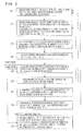
- Fig. 3 is a flowchart of a process of the periodicity judging device 7 and the defect judging device 8.
- Figs. 4A and 4B are explanatory views of computational processings thereof.
- the first small area selection unit 72 selects h in the width direction and an area 1 (reference region) having a size of 1 in the rolling direction in the measured range.
- the initial value of d used in Step S2 and the following steps described later may be set to a value of the smallest roll circumferential length (minimum value of a periodic defect).
- the second small area selection unit 74 selects an area 2 having the same size as the area 1 at the same position as the area 1 in the width direction and at a position apart from the area 1 by the distance d in the rolling direction as viewed from the area 1.
- an area 3 is selected at a position apart from the area 1 by a distance 2d
- an area 4 is selected at a position apart from the area 1 by a distance 3d
- an area 5 is selected at a position apart from the area 1 by a distance 4d.
- the area 1 corresponds to the first small area and the areas 2 to 5 corresponds to the second small area.
- Equation 1 The similarity evaluation index computation unit 76 calculates Equation 1 at a position where the areas 1 and 2 are corresponding to each other to calculate a correlation value R 12 of the areas 1 and 2.
- x (i, j) is a value at the i-th position in the width direction and the j-th position in the rolling direction in the total range where the digitized sensor outputs are measured.
- R 12 ⁇ i ⁇ j x i j * x ⁇ i , j + d
- Equation 2 is calculated, and correlation values R23, R34, and R45 are obtained at corresponding parts of the areas 2 and 3, the areas 3 and 4, and the areas 4 and 5.
- R 23 ⁇ i ⁇ j x ⁇ i , j + d * x ⁇ i , j + 2 ⁇ d
- R 34 ⁇ i ⁇ j x ⁇ i , j + 2 ⁇ d * x ⁇ i , j + 3 ⁇ d
- R 45 ⁇ i ⁇ j x ⁇ i , j + 4 ⁇ d * x ⁇ i , j + 5 ⁇ d
- the similarity evaluation index computation unit 76 calculates Equation 3), and adds the correlation values R12, R23, R34, and R45, thereby determining the similarity evaluation index R.
- the processing aims at eliminating influences of variation or deviation for each area of a plurality of areas whose correlation values are added, and is a specific processing of detecting a periodic defect.
- R R 12 + R 23 + R 34 + R 45
- the periodicity judgment unit 77 judges that there is a periodic defect candidate when the similarity evaluation index R is equal to or higher than the threshold set beforehand.
- Steps S2 to S5 are repeated.
- ⁇ is a fixed number smaller than the size 1 in the rolling direction of a given area.
- ⁇ ⁇ 1 ⁇ 2 is preferable.
- the changing range of d is adjusted to the range where periodic defects may be generated (given range of S6 of Fig. 3 ). In a line of the steel sheet 1, it is preferable that the range cover the circumferential direction of a roll provided in the line where a roll mark may be generated.
- the d may be changed in the range around an expected circumferential length of each roll (e.g., range of about several 10 mm). Therefore, when the circumferential direction of each roll in the line is remarkably different from each other, and there is a range where periodic defects are not generated, it is not necessary to set the value of d in the range.
- an expected circumferential length of each roll e.g., range of about several 10 mm. Therefore, when the circumferential direction of each roll in the line is remarkably different from each other, and there is a range where periodic defects are not generated, it is not necessary to set the value of d in the range.
- the initial value of d is set to the smallest roll circumferential length in Step S1 above.
- the initial value of d in S1 may be set to the value of q. More specifically, when the computation is always performed until the value of the position q reaches the maximum defect period value (value of the maximum roll circumferential length) from 0, the calculation is overlapped in the range where the q exceeds the d. Thus, when the calculation is not performed in the case where the q exceeds the d, efficient calculation can be performed. Thus, such calculation is preferable.
- (S8) S1 to S7 above are repeated while shifting the position of the area 1 serving as the basis of the similarity evaluation in the width direction.
- the shift amount at this time is preferably smaller than 1/2 of the size h in the width direction of the area for evaluation without omission.
- the defect judging device 8 judges whether the defect candidate is a defect from numerical values of the signal strength, length in the width direction, length in the rolling direction, and defect shape of the defect candidate, and outputs the result with the period d obtained by the periodicity judging device 7 when the defect candidate is judged to be a defect.
- the judgment may be performed after the S/N is improved by subjecting signals of a defect part to synchronous addition based on the period obtained by the periodicity judging device 7. Then, S9 is completed, the process returns to Step S6.
- the flowchart is an example of the procedure and the procedure may be suitably changed.
- the interval d is repeatedly changed in the process of repeatedly changing the position of the area 1, and may be vice versa. It has been described that the evaluation of the similarity evaluation index R of S5 is performed whenever the similarity performance index R is calculated. However, the evaluation of the similarity performance index R may be performed after all the repetitions are completed. When the one-dimensional data are targeted, it is not necessary to change the position in the width direction of the data area 1 of S8.
- the synchronous addition may be performed in the range having the same size (or substantially the same) as the area 1. This is because the position and the period of the defect candidate are clarified in the prior step. Most briefly, it can be realized by adding signals of the areas 1, 2, 3, 4, and 5 at the time when it is judged that the defect candidate is contained. Equation 4 represents an equation for calculating a synchronous addition value y (i, j). When a value of y (i, j) exceeds a specified value, the candidate is judged to be a defect. The calculation can be simplified by performing thus. In particular, since addition between narrow areas is simply performed, the calculation amount can be remarkably saved.
- a noise level N is determined on-line.
- the candidate may be judged to be a defect (i.e., judged to be a defect in the case of S/N > 3).
- the N may be determined based on the maximum value or average square error of a given area.
- the S/N is improved by performing integration in the width direction for the same position in the rolling direction. Thus, such a case is preferable.
- defects can be easily detected even when the defect development period fluctuates and minor signals from minor periodic defects generated in rolls having various diameters can be detected with high accuracy.
- the resolution of the defect signal is generally increased.
- the judgment processing i.e., detection of a periodic defect candidate
- the defect signal judging the degree of harmfulness of the defect utilizing the information of the period or generation position of the defect is emphasized, and the type, degree, and the like of the defect are judged as a second stage.
- Step S5 Detection of defect candidate (Step S5) by periodicity evaluation (Repetition of similarity evaluation by a correlation operation: Steps S1 to S8 above)
- Step S9 It is judged whether the defect candidate is a defect or harmless by performing defect judgment.
- the processing is performed in two stages, and a final defect judgment is performed in the second stage. Accordingly, the evaluation may be roughly performed (over detection may be frequently performed) while lowering the resolution on the computation in the periodicity evaluation in the first stage. More specifically, the load of the computational processing is reduced by performing thus, and the processing rate can be increased.
- the processing method will be described below.
- the procedure of the second embodiment is the same as that of Fig. 3 described in the first embodiment and is performed in a stage prior to S1. Thus, the same description as the first embodiment is omitted.
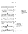
- Fig. 5 is a flowchart illustrating the process of the periodic judging device 7 and the defect judging device 8 according to the second embodiment.
- sampling pitch is measured as a value capable of detecting the smallest length of a detection target defect, and the measurement data are input.
- the measurement data are stored as they are in the data storage area 71 of Fig. 2 and are stored once as they are in a storage area for storing data for judging the degree of harmfulness of a defect (data memory or the like) (not shown) which is prepared for judging the degree of harmfulness of a defect.
- LPF Low Pass Filter; moving average may be acceptable
- This is performed to enable defect detection even when the defect position and the sampling position are shifted because the data are extracted at the time of performing periodicity computation in the following step. More specifically, this is performed to leave the defect signal information in the data left behind after the data extraction, considering a possibility that the defect signal does not remain when the date extraction is performed while the measurement data remaining as they are.
- Steps S1 to S8 are performed in the same manner as the first embodiment.
- the computation is performed using the data stored in the periodicity evaluation data storage area in place of the data of the data area 71.
- the defect judgment is performed by performing the processing of S9 described in the first embodiment using the data of the storage area for the data judging the degree of harmfulness of the defect.
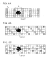
- the defect is easily omitted depending on the timing as shown in Fig. 6A .
- the smallest defect width of a detection target defect is defined as w and the spatial resolution in the width direction of the measurement signal is defined as w/2, for example, defect signals are obtained at least two data positions in the width direction.
- defect signals are obtained at four data positions in the width direction.
- the defect signals are obtained from a plurality of data positions in the width direction, and then are extracted while shifting the position in the rolling direction in the width direction as shown in Fig. 6B , for example, whereby the omission of the defect is suppressed.
- the shift amount may not be necessarily equivalent to one data position as shown in Fig. 6C .
- magnetization is performed in the longitudinal direction.
- sensors detecting a magnetic field in the vertical direction may be arranged in the width direction, and magnetization may be performed in the width direction.
- the magnetic flux generated due to a defect has positive and negative distributions in the width direction ( Fig. 8 ).
- the periodicity is evaluated, the similarity between the two-dimensional areas is evaluated in Embodiments 1 and 2.
- a probability of non-detection can be reduced to increase the periodicity evaluation accuracy even when data sampling as shown in Fig. 6 (C) is performed. This allows the periodicity evaluation even when extracted as described above.
- the computation is performed by selecting the two-dimensional area and the small area to evaluate the similarity in the two-dimensional area of the defect signals having two-dimensional characteristics, whereby the periodicity evaluation can be performed with higher accuracy.
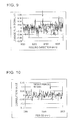
- Fig. 9 shows an example of defect detection of a minor irregularity defect originating from a roll generated in a steel sheet production line.
- a defect position is indicated by the arrow.
- the defect signals have small differences compared with noise signals, and thus are hard to be automatically detected.
- Fig. 10 shows results of performing an autocorrelation operation as an example of subjecting the signal to a general signal processing. Even when the autocorrelation operation is performed using the original signals, a defect period (1670 mm) cannot be detected due to a small difference between the defect signal and the noise signal.
- Figs. 11 and 12 show results of performing the signal processing of the first embodiment.
- Fig. 11 areas having a size of 8 mm in the width direction and 50 mm in the rolling direction are taken as a size of the first small area, and a correlation value of a pair of the areas is calculated to be used as a similarity evaluation index.
- the value of the similarity evaluation index R at the position (indicated by the arrow) of 1670 mm as the defect period is larger than that of another period. Therefore, in other words, it is recognized that the periodicity is strong (the value of the similarity evaluation index R is about 1.5 times larger than that of another period and the periodicity is about 1.5 times stronger than that of another period) and that the periodic defect exists.
- Fig. 12 correlation values of 4 pairs of combination of areas whose sizes are the same as Fig. 6 are calculated and added to be used as the similarity evaluation index.
- the value of a similarity evaluation function R is much larger than that of another period and the periodicity is higher than that of another period (the value of the similarity evaluation function R is about 4 to 5 times larger than that of another period and the periodicity is about 4 to 5 times stronger than that of another period), and that the periodic defect exists.
- the periodic defect discrimination accuracy can be further increased.
- the defect judgment can be performed by setting the differential threshold using the similarity evaluation index.
- the defect periodicity can be more clearly detected.
- the periodicity can be determined even when the correlation value between two areas is used as the similarity index.
- the similarity evaluation result i.e., reliability of the determined period, increases with an increase in the number of pairs of the areas whose correlation values are determined, however the calculation amount increases. From the relationship between the reliability of the results and the calculation amount, about 3 to 5 pairs are appropriate, and the 4 pairs as above are optimal.
- the correlation values of the 4 pairs of areas are added to be used as the similarity evaluation index.
- Another method such as multiplication or addition with a weight, may be used.
- two pairs of adjacent areas are selected as areas whose correlation values are determined. This is important for reducing influences of shift (deviation) in the width direction as much as possible in running of a target sample.
- deviation in the width direction referred to as meandering arises during running in a steel line, effects by the calculation method are large.
- 2 pairs of areas are not necessarily adjacent to one another. For example, by calculating correlations between the first reference position and each of a second area, a third area, a fourth area ..., the calculation can be simplified.
- the similarity evaluation method an example of a method using a correlation value is described as the similarity evaluation method.
- another similarity evaluation method such as a differential integration processing, may be used.
- Figs. 13 and 14 show the results of changing the size of the first small area.
- Figs. 13 and 14 correspond to Figs. 11 and 12 , respectively, and calculation is performed under the same conditions except adjusting the size of the first small area to be 100 mm in the rolling direction.
- the measurement data show that the similarity evaluation value becomes worse when the size is adjusted to be 100 mm in the rolling direction, and the similarity evaluation value varies in accordance with the size of the area. This is because when the size of the first small area excessively increases compared with the defect size, the number of data of noise signals increases relative to the number of data of defect signals, which increases influences of the noise signals, resulting in poor S/N of the correlation value.
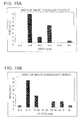
- the present inventors have examined a distribution of sizes of defects generated in a continuous annealing line. As a result, the present inventors found that most of the defects had a length in the width direction of about 2 mm to about 8 mm and a length in the rolling direction of about 3 mm to 50 mm as shown in Figs. 15A and 15B .
- the similarity evaluation index R was calculated (Equation 3) while changing the widths (h) and lengths (1) of the window frames of areas (first and second small areas) whose correlation values are calculated relative to samples whose sizes were partially changed (the smallest defect size (3 mm in length ⁇ 3 mm in width), the largest defect size (50 mm in length ⁇ 10 mm in width)). Typical results are shown in Figs. 16A and 16B .
- the axis of ordinate of each of Figs. 16A and 16B represents a ratio (referred to as S/N) of the evaluation index values of the defect parts and the parts free from defects.
- an applicable range of the small area is in the range of a length of 10 mm to 100 mm and a width of 1 mm to 30 mm (S/N ⁇ 2)
- an optimum range thereof is in the range of a length of 20 mm to 80 mm and a width of 2 mm to 20 mm (S/N ⁇ 25)
- a more optimum range thereof is in the range of a length of 25 mm to 62 mm and a width of 7 mm to 11 mm (S/N ⁇ 3).
- the S/N become 2 or more, which can be applied to automatic defect detection.
- the S/N becomes 3 or more, which is found to be optimal.
- the measurement signal by the magnetic sensor of this example has an about 10 mm spread in the rolling direction as shown in Fig. 17 , a large difference does not appear in the optimum range compared with the relative ratio of the defect size in Fig. 9 .
- the lower limit of the optimum range may be the maximum defect size.
- the upper limit of the optimum range is considered to be based on the spread of the measurement signal.
- the optimum range is equal to or higher than 1/4 of the maximum defect size and is equal to or lower than 10 times the smallest spread of the signal, more preferably equal to or higher than 2/5 of the maximum defect size and is equal to or lower than 8 times the smallest spread of the signal, and still more preferably equal to or higher than 1/2 of the maximum defect size and is equal to or lower than 6 times the smallest spread of the signal.
- leakage-flux defect detection is not necessarily used and another method may be used insofar as the method evaluates the properties of a target sample.
- Another defect detection method such as a surface defect meter using a usual camera, a sensor using infrared light, a thermography, an ultrasonic sensor, or an eddy current sensor, may be used.
- a magnetic sensor such as a hall element, a coil, a magnetic resistance element, or SQUID
- a method in which one or a plurality of sensors are traversed may be used.
- the defect detection is performed over the entire width, a method in which the defect detection is performed in a partial area in the width direction may be used.
- a method may be used in which the defect detection is performed in a partial area in the width direction to a certain length, and then the defect detection is repeatedly performed while changing the position in the width direction.
- the magnetizer 3 is provided so that the magnetic flux flows in the width direction of the steel sheet.
- a pair of the magnetizer and the magnetic sensor is faced with each other across the steel sheet 1, but may be provided on the same side.
Landscapes
- Chemical & Material Sciences (AREA)
- General Health & Medical Sciences (AREA)
- Immunology (AREA)
- Physics & Mathematics (AREA)
- Health & Medical Sciences (AREA)
- Life Sciences & Earth Sciences (AREA)
- Analytical Chemistry (AREA)
- Biochemistry (AREA)
- General Physics & Mathematics (AREA)
- Pathology (AREA)
- Electrochemistry (AREA)
- Chemical Kinetics & Catalysis (AREA)
- Engineering & Computer Science (AREA)
- Textile Engineering (AREA)
- Investigating Or Analyzing Materials By The Use Of Magnetic Means (AREA)
- Investigating Materials By The Use Of Optical Means Adapted For Particular Applications (AREA)
- Investigating Or Analyzing Materials By The Use Of Ultrasonic Waves (AREA)
- Length Measuring Devices By Optical Means (AREA)
Abstract
Description
- The present invention relates to a periodic defect detection apparatus that detects periodic defects periodically generating in belt-like bodies or columnar bodies formed of metal, plastics, or other materials and a method therefore.
- In production lines of belt-like bodies or columnar bodies, a roll is sometimes used in order to convey products. When a certain trouble arises in a production process, defects originating from the roll are sometimes formed on a steel sheet. A method for detecting the defects will be described taking an example of a process for particularly producing a steel sheet.
- In the production process of a steel sheet, periodic defects referred to as roll marks are sometimes formed. The roll marks are formed when foreign materials adhering to the roll provided in the production line or irregularities produced on the roll itself when the foreign materials bite into the roll are transferred to a steel sheet. The periodic defects are generated when the irregularities produced on the roll are transferred to a steel sheet. When generated once, the periodic defects are successively generated until the roll is exchanged or the process is improved. Therefore, it is extremely important also in terms of improvement in yield to discover the periodic defects at an early stage and to take a measure for dealing with the periodic defects.
- Heretofore, many detection methods focusing on the periodicity of the periodic defects have been proposed as a method for detecting the periodic defects.
- The technique disclosed in
Patent Document 1 is one of the methods utilizing the periodicity. According to the method, a target sample is measured by a defect detection sensor first, sensor output signals are subjected to synchronous addition at an expected period (length equivalent to one rotation of a final pressure roll in a steel line in Patent Document 1), and a defect signal having a period is emphasized from other noise components having no period. However, the method cannot be used for cases other than a case where the period is expected beforehand. For example, in the steel production line, the roll causing the defects is worn out, which changes the diameter of the roll in some cases. When the diameter varies, a defect development period naturally varies, and thus the above-described method is difficult to apply. - Heretofore, in order to deal with the problem such that the defect development period varies, some methods have been proposed.
- Mentioned as a first method is a method including measuring a target sample by a defect detection sensor, subjecting sensor output signals to threshold treatment to extract a plurality of defect candidates, and comparing intervals between the plurality of defect candidates to judge that, when the intervals are in agreement with each other, the periodic defects are generated at the agreement interval as a period. However, when the method is actually applied, the following problems arise.
- In an actual production line, a degree of contact between a roll and a steel sheet is not always constant. For example, the rolling reduction varies in a reduction roll. When the contact between the roll and the steel sheet is weak, a defect level is low. Therefore, a defect signal also becomes weak, and thus is not detected in some cases. Moreover, signals of slight unevenness, such as a sudden defect having no periodicity, surface roughness of a steel sheet that is originally harmless, or magnetic properties (in the case of a magnetic detection device), are detected, and they sometimes arise while being mixed with periodic defects. Therefore, the method for detecting periodicity simply by comparing the intervals between the defect candidates has problems in that the intervals between the defect candidates are not in agreement with each other due to non-defection of defect candidates or noises, such as sudden defects or over detection, and thus, periodic defects and the periodicity thereof cannot be accurately detected.
- Known as a second method for dealing with the problem such that the defect development period varies is a detection method utilizing autocorrelation (e.g., Patent Document 2).
- The distance between peaks obtained based on computation results of autocorrelation represents a period of periodic signal components. Therefore, even when the period of the periodic signal components contained in a signal series to be processed is unknown, only the periodic signal components can be selectively extracted from the signal series buried in noise. However, the detection method utilizing autocorrelation also has a problem in that, when many noise components are contained in sensor output signals from a target sample, a periodicity judgment accuracy decreases. The detection method also has a problem in that, when a detection sensitivity is lowered so as to suppress the over detection, minor signals from minor defects cannot be detected.
- Mentioned as a third method for dealing with the problem such that the defect development period varies is a detection method disclosed in
Patent Document 3, for example. - The detection method includes successively picking up images of the surface of a moving belt-like body or the like, cutting out a template image T from the picked-up images, and comparing image similarity between the template image T and a target image G whose length in the longitudinal direction is longer than a target roll circumferential length to detect periodicity. According to the method, in order to accurately determine a defect period, correlations of not only defect parts but base-design parts of parts free from defects are calculated. Therefore, the image similarity is compared in the range equal to or more than one roll rotation. According to the method, in a stage of evaluating the image similarity between the template image and the target image, the similarity is evaluated by gradually shifting a relative position of the mutual images. Therefore, the method can be applied to the case where the diameter of the roll gradually varies due to abrasion. However, the method has problems in that the method cannot be applied to rolls other than a roll on which a base pattern is formed, i.e., a final reduction roll before inspection, because the base pattern of parts free from defects is utilized for obtaining period information.
- In an actual production line of a steel sheet, it is necessary to detect not only defects originating from a roll generated in the final reduction roll before inspection but such defects that have been generated before. Specifically, in the case of cold rolling, it is necessary to detect defects in a reduction roll in one stage or two stages prior to the final reduction roll, defects in a roll in an annealing furnace prior to a final temper rolling roll in a CAL line, defects originating from the roll generated during cold rolling, etc. Therefore, it is necessary to detect defects generated in a plurality of rolls having different diameters. However, the detection method of
Patent Document 3 cannot be applied to the case. - Patent-Document 1: Japanese Unexamined Patent Application Publication No.
6-324005 - Patent Document 2: Japanese Unexamined Patent Application Publication No.
58-156842 - Patent Document 3: Japanese Unexamined Patent Application Publication No.
2006-105791 - It is an object of the present invention to provide a device for detecting periodic defects of a belt-like body or the like which can be used even when the defect development period varies and which can judge, with a high degree of accuracy, periodic defects generated not only in a reduction roll but in a plurality of rolls having different diameters, particularly even when the defects are minor, and a method therefor.
- First, the present inventors have examined problems of a former correlation operation.
Fig. 18 schematically illustrates an example of a correlation operation to measurement signals of usual periodic defects. Utilizing the fact that a correlation coefficient value increases when signal wave forms of a reference signal and an input signal are completely in agreement with each other or have high similarity, the period of the periodic defects is determined from the interval between parts having a high correlation value. However, when applied to detection of periodic defects, a reference signal is cut out from an input signal (i.e., a sensor measurement signal in the case of defect detection) and created. Thus, as shown inFig. 19 , when the S/N of the input signal is low, the S/N of a correlation operation does not increase. - To avoid the above, the present inventors have reached the present invention for increasing the S/N focusing on a feature that, when a periodic defect is generated once, a plurality of defects are repeatedly generated (e.g., 5 times or more). The correlation operation has an advantage in that a period can be calculated based on data for one period, but is not computation utilizing data for a plurality of periods. In contrast, in the present invention, improvement in S/N is achieved utilizing data for a plurality of periods.
- The present inventors have also obtained a finding that a data area (number of data) in which a correlation operation is performed has a preferable range for further improvement in S/N. More specifically, it has been found to be preferable that the data area in which a correlation operation is performed contain data of defect signals in a higher proportion.
- The present invention has been made based on the above findings, and is structured as described below.
- An apparatus for detecting periodic defect according to the present invention comprises:
- a sensor for obtaining signals for evaluating properties of an area having a length longer than an expected defect period on a target sample;
- a small area selection means for separating a plurality of small areas whose area length is shorter than that of the area so that all distance intervals adjacent to one another are equal in a periodic defect arrangement direction to determine positions of the plurality of small areas, and selecting signals corresponding to the positions of the plurality of small areas from outputs from the sensor;
- an evaluation index calculation means for calculating a similarity evaluation index between signal patterns among a plurality of signals selected by the small area selection means;
- a set value changing means for changing the positions of the small areas and the distance interval, and repeating computational processings of the small area selection means and the evaluation index calculation means; and
- a period judgment means for judging the distance interval as a period when the evaluation index is higher than a value set beforehand.
- In the apparatus for detecting periodic defect according to the present invention, the small area selection means is preferably as follows.
- In the apparatus for detecting periodic defect according to the present invention,
the small area selection means has: - a first small area selection means for determining one position of the small area whose length is shorter than the area to define the area as a first small area, and selecting a signal corresponding to the position of the first small area from the sensor output; and
- a second small area selection means for disposing a plurality of second small areas in a periodic defect arrangement direction on the basis of the position of the first small area while separating the second small areas so that all distance intervals are equal, and selecting signals corresponding to the positions of the plurality of second small areas from the sensor output, and
- the set point changing means changes the position of the first small area and the distance interval, and repeats computational processings of the small area selection means and the evaluation index calculation means.
- In the apparatus for detecting periodic defect according to the present invention, the sensor is preferably a magnetic sensor that magnetizes a target sample formed of a magnetic metal component, and obtains a leakage flux signal.
- In the apparatus for detecting periodic defect according to the invention, it is preferable that the length of the small area be substantially the same as the length of an expected largest defect.
- In the apparatus for detecting periodic defect according to the present invention, it is preferable for the evaluation index calculation means to calculate a value for evaluating similarity for each small area, and combine the values to determine the evaluation index.
- In the apparatus for detecting periodic defect according to the present invention, it is preferable for the evaluation index calculation means to calculate a value for evaluating similarity for each small area, and add the values to obtain the evaluation index.
- In the apparatus for detecting periodic defect according to the present invention, it is preferable that the value for evaluating similarity for each small area be a correlation value between the small areas.
- An apparatus for detecting periodic defect according to the present invention comprises:
- a sensor for obtaining signals for evaluating properties of a two-dimensional area whose length is longer than an expected defect period on a target sample;
- a periodicity judgment means for obtaining a periodic defect candidate based on an output from the sensor; and
- a defect judgment means for judging at least the existence of a defect based on the defect candidate and the sensor output,
- in which the periodicity judgment means performs:
- first computational processing for repeating a processing of selecting a first two-dimensional small area smaller than the two-dimensional area in the two-dimensional area, selecting a plurality of second two-dimensional small areas separated at a given distance in the periodic defect arrangement direction from the first two-dimensional small area in such a manner as to have the same size as the first two-dimensional small area, calculating a similarity evaluation index between signal patterns of the sensor outputs corresponding to the two-dimensional small areas, respectively, to evaluate similarity, and judging that, when the similarity is evaluated to be high, a defect candidate exists in each two-dimensional small area at the distance as a period, while changing the distance, and
- second computational processing for repeating the first computational processing until the first two-dimensional small area covers a given range in the original two-dimensional area while changing the position of the first two-dimensional small area in the original two-dimensional area when the first computational processing is repeated until the distance covers the range of a period where the periodic defect may be generated.
- A method for detecting periodic defect according to the present invention comprises:
- (a) a signal inputting step of obtaining sensor outputs for evaluating properties of an area whose length is longer than that of an expected defect period on a target sample,
- (b) a small area selecting step of separating a plurality of small areas whose area length is shorter than that of the area so that all distance intervals adjacent to one another are equal in a periodic defect arrangement direction to determine positions of the plurality of small areas, and selecting signals corresponding to the positions of the plurality of small areas from the sensor outputs;
- (c) an evaluation index calculation step of calculating a similarity evaluation index between signal patterns among a plurality of signals selected in the small area selecting step;
- (d) a set value changing step of changing the positions of the small areas and the distance interval, and repeating (b) and (c) above; and
- (e) a period judging step of judging the distance interval to be a period when the evaluation index determined in (c) above is higher than a value set beforehand.
- In the periodic defect detection method according to the present invention, the small area selecting step is preferably as follows.
- In the method for detecting periodic defect according to the present invention, the small area selecting step determines one position of the small area whose length is shorter than the area to define the area as a first small area, disposes a plurality of second small areas in a periodic defect arrangement direction on the basis of the position of the first small area while separating the second small areas so that all distance intervals are equal, and selects signals corresponding to the position of the first small area and the positions of the plurality of second small areas from the sensor outputs, and
the set point changing step repeats (b) and (c) above while changing the position of the first small area and the distance interval. - The method for detecting periodic defect according to the invention includes:
- a first step of obtaining sensor outputs for evaluating properties of a two-dimensional area whose length is longer than an expected defect period on a target sample;
- a second step of repeating a processing of selecting a first two-dimensional small area smaller than the two-dimensional area in the two-dimensional area, selecting a plurality of second two-dimensional small areas separated at a given distance in the periodic defect arrangement direction from the first two-dimensional small area in such a manner as to have the same size as the first two-dimensional small area, calculating a similarity evaluation index between signal patterns of the sensor outputs corresponding to the two-dimensional small areas, respectively, to evaluate similarity, and judging that, when the similarity is evaluated to be high, a defect candidate exists in each two-dimensional small area at the distance as a period, while changing the distance;
- a third step of repeating the second step until the first two-dimensional small area covers a given range in the original two-dimensional area while changing the position of the first two-dimensional small area in the original two-dimensional area when the first computational processing is repeated until the distance covers the range of a period where the periodic defect may be generated;
and - a fourth step of judging at least the existence of a defect based on the defect candidate and the sensor output.
- The present invention has a sensor for obtaining signals for evaluating properties of an area having a length longer than an expected defect period on a target sample; a small area selection means for separating a plurality of small areas whose area length is shorter than that of the area so that all distance intervals adjacent to one another are equal in a periodic defect arrangement direction to determine positions of the plurality of small areas, and selecting signals corresponding to the positions of the plurality of small areas from outputs from the sensor; an evaluation index calculation means for calculating a similarity evaluation index between signal patterns among a plurality of signals selected by the small area selection means; a set value changing means for changing the positions of the small areas and the distance interval, and repeating computational processings of the small area selection means and the evaluation index calculation means; and a period judgment means for judging the distance interval as a period when the evaluation index is higher than a value set beforehand. Therefore, even when the defect development period fluctuates, the defects can be easily detected and minor signals from minor periodic defects generating in rolls having various diameters can be detected with high accuracy.
- The present invention has (a) a signal inputting step of obtaining sensor outputs for evaluating properties of an area whose length is longer than that of an expected defect period on a target sample, (b) a small area selecting step of separating a plurality of small areas whose area length is shorter than that of the area so that all distance intervals adjacent to one another are equal in a periodic defect arrangement direction to determine positions of the plurality of small areas, and selecting signals corresponding to the positions of the plurality of small areas from the sensor outputs; (c) an evaluation index calculation step of calculating a similarity evaluation index between signal patterns among a plurality of signals selected in the small area selecting process; (d) a set value changing step of changing the positions of the small areas and the distance interval, and repeating (b) and (c) above; and (e) a period judging step of judging the distance interval to be a period when the evaluation index determined in (c) above is higher than a value set beforehand. Therefore, even when the defect development period fluctuates, the defects can be easily detected and minor signals from minor periodic defects generating in rolls having various diameters can be detected with high accuracy.
-
-
Fig. 1 is a block diagram of a periodic defect detection device according to a first embodiment. -
Fig. 2 is a view of an example of a functional block of a periodicity judging device of the first embodiment. -
Fig. 3 is a flowchart of a process of the periodicity judging device and the defect judging device of the first embodiment. -
Figs. 4A and 4B are explanatory views of a computational processing by the periodicity judging device. -
Fig. 5 is a flowchart of a process of a periodicity judging device and a defect judging device of a second embodiment. -
Figs. 6A to 6C are explanatory views of the relationship between a data sampling pitch and defect detection. -
Fig. 7 is a block diagram of a periodic defect detection device according to a third embodiment. -
Fig. 8 is a schematic view of transverse magnetization. -
Fig. 9 shows an example of defect detection of a minor irregularity defect originating from a roll generated in a steel sheet production line. -
Fig. 10 is a view illustrating results of performing autocorrelation of a leakage flux signal ofFig. 9 . -
Fig. 11 is an example (No. 1) of a similarity evaluation index R obtained by a signal processing of the first embodiment. -
Fig. 12 is an example (No. 2) of a similarity evaluation index R obtained by the signal processing of the first embodiment. -
Fig. 13 is an example (No. 3) of a similarity evaluation index R obtained by the signal processing of the first embodiment. -
Fig. 14 is an example (No. 4) of a similarity evaluation index R obtained by the signal processing of the first embodiment. -
Figs. 15A and 15B are views illustrating inspection results of a distribution of sizes of defects generated in a continuous annealing line. -
Figs. 16A and 16B are views illustrating an example of S/N of the similarity evaluation index R obtained by changing the window length and the window width of the area with respect to the data ofFig. 15 . -
Fig. 17 is a view illustrating an example of a measurement signal of the first embodiment. -
Fig. 18 is an explanatory view illustrating a former periodic defect detection method. -
Fig. 19 is an explanatory view illustrating a former periodic defect detection method. -
Figs. 20A to 20C are explanatory views illustrating the principle of the periodic defect detection method of the present invention. -
- 1
- steel sheet, 2 defect, 3 magnetizer
- 4
- magnetic sensor, 5 signal preprocessing device
- 6
- A/D converter, 7 periodicity judging device
- 8
- defect judging device, 71 data storage area
- 72
- first small area selection unit
- 73
- first small area data setting unit
- 74
- second small area selection unit
- 75
- second small area data setting unit
- 76
- similarity evaluation index computation unit
- 77
- period judgment unit,
- 78
- judgment result storing unit
- The detection principle of a periodic defect of the present invention will be described with reference to
Figs. 20A to 20C . - For ease of understanding,
Figs. 20A to 20C illustrate using a one-dimensional data row, but can be applied to the case of a two-dimensional data row as mentioned later. First, as shown inFig. 20A , the case where a firstsmall area 1 containing a defect is taken, and secondsmall areas small area 1 and each of the secondsmall area - Thus, as shown in
Fig. 20A , when a defect position is contained in the first small area and a distance interval d is exactly in agreement with the defect period P0, all the correlation values become large. Thus, the similarity evaluation index R relating thereto surely becomes a large value. In contrast, when a defect is not contained in the first small area or the distance interval d is not in agreement with the defect period P0, all the values do not become large even when any of the correlation values happens to be large. Thus, the similarity performance index R does not become large. The invention has been made based on the above-described idea. For example, as shown inFig. 20C , the similarity evaluation index R for each set distance interval d is determined while gradually changing the distance interval d as represented by d' (= d +Δd). When the distance interval d covers a given range (e.g., to the maximum length of an expected defect period), the calculation of the similarity evaluation index R is repeated while changing the position q of the first small area in the same manner as above. Then, the periodic defect period is determined from the distance interval d in the case where the similarity evaluation index R becomes larger than a value set beforehand or becomes the maximum value. - The principle of the invention is describe as above, and will be described in detail with reference to the following embodiments.
-
Fig. 1 is a schematic view of a periodic defect detection device according to a first embodiment.Fig. 1 includes a steel sheet 1 (which is shown in a perspective view so that devices disposed under the steel sheet are easily recognized), aperiodic defect 2, amagnetizer 3, amagnetic sensor 4, asignal preprocessing device 5 containing an amplifier and a filter circuit, an A/D converter 6, aperiodic defect detector 7, and adefect judging device 8. - It is supposed that, in this example, a plurality of roll-causing surface defects originating from a reduction roll exists as the
periodic defect 2 in the rolling direction (moving direction inFig. 1 ) in thesteel sheet 1. More than one pair of themagnetizer 3 and themagnetic sensor 4 are disposed facing with each other across thesteel sheet 1 along the width direction (direction orthogonal to the periodic defect arrangement direction) of thesteel sheet 1. Themagnetizer 3 is magnetized by a direct current applied thereto from a magnetization power source (not shown). The magnetic flux generated by themagnetizer 3 between both the magnetic poles passes through thesteel sheet 1. Here, themagnetizer 3 is disposed so that the magnetic flux flows in the width direction of thesteel sheet 1. Here, a pair of the magnetizer and the magnetic sensor is disposed facing with each other across thesteel sheet 1, but may be provided on the same side. When theperiodic defects 2 exist in thesteel sheet 1, the magnetic flux is hindered by theperiodic defect 2. The change in the magnetic flux can be detected by themagnetic sensor 4. - In the example of
Fig. 1 , the moving direction shown inFig. 1 corresponds to the periodic defect arrangement direction. Thus, theperiodic defect 2 reaches the position of themagnetic sensor 4 in accordance with the movement of thesteel sheet 1 conveyed by a rolling line or the like. Then, signals change each time. Therefore, when measurement signals of themagnetic sensor 4 are collected as a serial data according to the movement amount (i.e., position of the steel sheet 1) in the moving direction of the steel sheet, measurement data (signals for evaluating properties) in the arrangement direction of theperiodic defects 2 can be obtained. - Here, it is necessary to obtain measurement data for a distance (moving distance of the steel sheet) longer than that of the maximum value (based on the maximum roll circumferential length when a plurality of reduction rolls are provided) of an expected defect period of the
periodic defects 2. Thus, it may be structured so that measurement data for a plurality of periods, e.g., about 3 to 5 periods, is obtained. However, the structure is not limited thereto. As described later, the S/N is improved by performing computation while increasing the number of the periods, and then collecting data. Thus, the upper limit may be suitably determined in accordance with a degree of a signal S/N of a measurement target. - In the case of a sensor capable of measuring the
steel sheet 1 over the entire width direction at one time, the measurement can be performed throughout the entire length in the longitudinal direction of thesteel sheet 1. Thus, in such a case, a plurality of periods are measured, causing no problems. In general, in the case of periodic defect inspection, a sensor of measuring only a part of thesteel sheet 1 in the width direction is employed, and the measurement is performed by traversing the sensor from the viewpoint of cost in some cases. In such a case, the measurement is performed for the periods set above at the same width position (length equal to or longer than a plurality of lengths of the maximum period, e.g., about 3 to 5 periods), and then the width position may be moved. - The output signals thus obtained of the
magnetic sensor 4 are amplified by the amplifier built into thesignal preprocessing device 5, noise is removed in a filter circuit built into thesignal preprocessing device 5, and then the signals are sent to the A/D converter 6. - In the A/
D converter 6, the analog signal is sampled and digitized so that the pitches are equal to each other on thesteel sheet 1. For example, a sampling pulse can be obtained by, for example, bringing a rotary encoder into contact with thesteel sheet 1. The data digitized by the A/D converter 6 are sent to theperiodicity judging device 7. Here, periodicity judgment shown inFig. 2 is performed. A sampling pitch as used herein refers to a spatial resolution when a signal of themagnetic sensor 4 is converted to digital data, and stored in a data memory, and may be set to a value (e.g., 1/2 of the smallest length or lower) allowing detection of the smallest length of a defect as a detection target. -
Fig. 2 is an explanatory view of an example of a functional block view of theperiodicity judging device 7. - The
periodicity judging device 7 has adata storage area 71 for memorizing raw data of the A/D-converted measurement data as they are (here, a two-dimensional data row because a plurality ofmagnetic sensors 4 are disposed in the width direction), a first smallarea selection unit 72 for selecting data of the first small area, a first small areadata setting unit 73 for setting the size and position of the small area at the time of selecting the data of the first small area, a second smallarea selection unit 74 for selecting data of a second small area, a second small areadata setting unit 75 for setting the size and distance interval of the second small area at the time of selecting the data of the second small area, a similarity evaluationindex computation unit 76 for calculating a similarity evaluation index by inputting the data selected from the first small area selection unit and the second small area selection unit, aperiodicity judgment unit 77 for judging the existence of periodicity from the similarity evaluation index, and a judgmentresult storage unit 78 for storing the judgment results, and outputting the results to a defect judgment unit. - In the first small region
data storage unit 73, the position of the first small region is successively changed, and set in the first small region selection unit. In the second small regiondata storage unit 75, the distance interval of the second small region is successively changed, and the position of the second small region is set in the second smallregion selection unit 74. - Then, computation of the similarity performance index is repeatedly performed. The size of the small area is fixed while repeatedly performing the computation. A value of the size of the small area set in by the first small area
data selection unit 73 is output to the second smallarea selection unit 74, and is set to the same value. When the calculated evaluation index is evaluated to be a high similarity value, theperiodic judgment unit 77 determines periodicity from the distance interval at that time and the area where a periodic defect candidate exists from the position at that time. -
Fig. 3 is a flowchart of a process of theperiodicity judging device 7 and thedefect judging device 8.Figs. 4A and 4B are explanatory views of computational processings thereof. - (S1) As shown in
Fig. 4A , the first smallarea selection unit 72 selects h in the width direction and an area 1 (reference region) having a size of 1 in the rolling direction in the measured range. The initial value of d used in Step S2 and the following steps described later may be set to a value of the smallest roll circumferential length (minimum value of a periodic defect). - (S2) As shown in
Fig. 4A , the second smallarea selection unit 74 selects anarea 2 having the same size as thearea 1 at the same position as thearea 1 in the width direction and at a position apart from thearea 1 by the distance d in the rolling direction as viewed from thearea 1. Similarly, anarea 3 is selected at a position apart from thearea 1 by adistance 2d, anarea 4 is selected at a position apart from thearea 1 by adistance 3d, and anarea 5 is selected at a position apart from thearea 1 by adistance 4d. - The
area 1 corresponds to the first small area and theareas 2 to 5 corresponds to the second small area. - (S3) The similarity evaluation
index computation unit 76 calculatesEquation 1 at a position where theareas areas Equation 1, x (i, j) is a value at the i-th position in the width direction and the j-th position in the rolling direction in the total range where the digitized sensor outputs are measured.
- Similarly,
Equation 2 is calculated, and correlation values R23, R34, and R45 are obtained at corresponding parts of theareas areas areas 
- (S4) The similarity evaluation
index computation unit 76 calculates Equation 3), and adds the correlation values R12, R23, R34, and R45, thereby determining the similarity evaluation index R. Here, the processing aims at eliminating influences of variation or deviation for each area of a plurality of areas whose correlation values are added, and is a specific processing of detecting a periodic defect.
- (S5) The
periodicity judgment unit 77 judges that there is a periodic defect candidate when the similarity evaluation index R is equal to or higher than the threshold set beforehand. - (S6) Next, as shown in
Fig. 4B , the distance d as a basis between the areas whose correlation values are calculated is changed to d + Δ (d + Δ = d). Then, Steps S2 to S5 are repeated. Here, Δ is a fixed number smaller than thesize 1 in the rolling direction of a given area. In order to evaluate without omission, Δ <1 < 2 is preferable. The changing range of d is adjusted to the range where periodic defects may be generated (given range of S6 ofFig. 3 ). In a line of thesteel sheet 1, it is preferable that the range cover the circumferential direction of a roll provided in the line where a roll mark may be generated. The d may be changed in the range around an expected circumferential length of each roll (e.g., range of about several 10 mm). Therefore, when the circumferential direction of each roll in the line is remarkably different from each other, and there is a range where periodic defects are not generated, it is not necessary to set the value of d in the range. - (S7) The position q of the
area 1 as the basis of similarity evaluation is shifted by Δq in the rolling direction, and S1 to S6 above are repeated. One shift amount Δq at this time is preferably smaller than 1/2 of thesize 1 in the rolling direction of the area for evaluation without omission. The lower limit of the shit amount Δq is a sampling period in the rolling direction where the digitized sensor outputs are measured, but may be suitably determined because it takes time to perform the computation. Then, by repeating S1 to S6 above until the position q of thearea 1 becomes the maximum defect period value (maximum roll circumferential length) (until a given range of S7 ofFig. 3 is covered), the evaluation can be performed without omission. The initial value of d is set to the smallest roll circumferential length in Step S1 above. However, when the value of q becomes larger than the smallest roll circumferential length, the initial value of d in S1 may be set to the value of q. More specifically, when the computation is always performed until the value of the position q reaches the maximum defect period value (value of the maximum roll circumferential length) from 0, the calculation is overlapped in the range where the q exceeds the d. Thus, when the calculation is not performed in the case where the q exceeds the d, efficient calculation can be performed. Thus, such calculation is preferable. - (S8) S1 to S7 above are repeated while shifting the position of the
area 1 serving as the basis of the similarity evaluation in the width direction. The shift amount at this time is preferably smaller than 1/2 of the size h in the width direction of the area for evaluation without omission. - (S9) When it is judged that there is a periodic defect candidate in the judgment of S5 as a result of performing the above periodicity evaluation, signal data of the positions in the rolling direction and the width direction, the length of a period, and the area of the periphery of the defect candidate are stored in the judgment
result storage unit 78 and are transmitted to thedefect judging device 8. The positions in the rolling direction and the width direction of the defect candidate are determined from the position of the area 1 (or thearea - The
defect judging device 8 judges whether the defect candidate is a defect from numerical values of the signal strength, length in the width direction, length in the rolling direction, and defect shape of the defect candidate, and outputs the result with the period d obtained by theperiodicity judging device 7 when the defect candidate is judged to be a defect. In thedefect judging device 8, the judgment may be performed after the S/N is improved by subjecting signals of a defect part to synchronous addition based on the period obtained by theperiodicity judging device 7. Then, S9 is completed, the process returns to Step S6. - The flowchart is an example of the procedure and the procedure may be suitably changed. For example, the interval d is repeatedly changed in the process of repeatedly changing the position of the
area 1, and may be vice versa. It has been described that the evaluation of the similarity evaluation index R of S5 is performed whenever the similarity performance index R is calculated. However, the evaluation of the similarity performance index R may be performed after all the repetitions are completed. When the one-dimensional data are targeted, it is not necessary to change the position in the width direction of thedata area 1 of S8. - When the signals of the defect part are subjected to synchronous addition by the
defect judging device 8, the synchronous addition may be performed in the range having the same size (or substantially the same) as thearea 1. This is because the position and the period of the defect candidate are clarified in the prior step. Most briefly, it can be realized by adding signals of theareas Equation 4 represents an equation for calculating a synchronous addition value y (i, j). When a value of y (i, j) exceeds a specified value, the candidate is judged to be a defect. The calculation can be simplified by performing thus. In particular, since addition between narrow areas is simply performed, the calculation amount can be remarkably saved. Moreover, based on the data that are judged to have no periodic defects in S5, a noise level N is determined on-line. When y (i, j) exceeds 3N, for example, the candidate may be judged to be a defect (i.e., judged to be a defect in the case of S/N > 3). The N may be determined based on the maximum value or average square error of a given area.
- When the defect ha a spread in the width direction, the S/N is improved by performing integration in the width direction for the same position in the rolling direction. Thus, such a case is preferable.
- As described above, in the first embodiment, by performing the above-described processing, defects can be easily detected even when the defect development period fluctuates and minor signals from minor periodic defects generated in rolls having various diameters can be detected with high accuracy.
- In usual, in order to increase accuracy for discriminating a harmless part of a defect, the resolution of the defect signal is generally increased. In the invention, as described in the first embodiment, the judgment processing (i.e., detection of a periodic defect candidate) of judging whether a periodic component is contained in the measurement signal is performed as a first stage. Then, when the periodic component is contained (when the periodic defect candidate is detected), the defect signal judging the degree of harmfulness of the defect utilizing the information of the period or generation position of the defect is emphasized, and the type, degree, and the like of the defect are judged as a second stage. First stage: Detection of periodic defect candidate
- Detection of defect candidate (Step S5) by periodicity evaluation (Repetition of similarity evaluation by a correlation operation: Steps S1 to S8 above)
- It is judged whether the defect candidate is a defect or harmless by performing defect judgment (Step S9).
- Thus, the processing is performed in two stages, and a final defect judgment is performed in the second stage. Accordingly, the evaluation may be roughly performed (over detection may be frequently performed) while lowering the resolution on the computation in the periodicity evaluation in the first stage. More specifically, the load of the computational processing is reduced by performing thus, and the processing rate can be increased.
- The processing method will be described below. The procedure of the second embodiment is the same as that of
Fig. 3 described in the first embodiment and is performed in a stage prior to S1. Thus, the same description as the first embodiment is omitted. -
Fig. 5 is a flowchart illustrating the process of the periodic judgingdevice 7 and thedefect judging device 8 according to the second embodiment. - (S11) A sampling pitch is measured as a value capable of detecting the smallest length of a detection target defect, and the measurement data are input.
- (S12) The measurement data are stored as they are in the
data storage area 71 ofFig. 2 and are stored once as they are in a storage area for storing data for judging the degree of harmfulness of a defect (data memory or the like) (not shown) which is prepared for judging the degree of harmfulness of a defect. - (S13) An LPF (Low Pass Filter; moving average may be acceptable) is used in the rolling direction of the input data (measured signal). This is performed to enable defect detection even when the defect position and the sampling position are shifted because the data are extracted at the time of performing periodicity computation in the following step. More specifically, this is performed to leave the defect signal information in the data left behind after the data extraction, considering a possibility that the defect signal does not remain when the date extraction is performed while the measurement data remaining as they are.
- (S14) Periodicity evaluation data is created in which the signals are extracted at a rate of 1 in several sampling pitches (e.g., at a rate of 1 in 4 times or 1 in 2 to 8 times) at which the data created in S13 are measured.
- (S15) The periodicity evaluation data created in S14 are stored in the
data storage area 71 ofFig. 2 . - (S16) Thereafter, Steps S1 to S8 are performed in the same manner as the first embodiment. In (S15), when the periodicity evaluation data storage area for storing the periodicity evaluation data is provided other than the
data storage area 71 and the periodicity evaluation data are stored therein, the computation is performed using the data stored in the periodicity evaluation data storage area in place of the data of thedata area 71. - (S17) When it is judged that there is periodicity, the defect judgment is performed by performing the processing of S9 described in the first embodiment using the data of the storage area for the data judging the degree of harmfulness of the defect.
- In the case of two-dimensional data, when successively extracted in the width direction at the same position in the rolling direction (data are used in a striped pattern in the width direction), the defect is easily omitted depending on the timing as shown in
Fig. 6A . In order to avoid such a condition, the smallest defect width of a detection target defect is defined as w and the spatial resolution in the width direction of the measurement signal is defined as w/2, for example, defect signals are obtained at least two data positions in the width direction. When defined as w/4, defect signals are obtained at four data positions in the width direction. - Thus, it is structured that the defect signals are obtained from a plurality of data positions in the width direction, and then are extracted while shifting the position in the rolling direction in the width direction as shown in
Fig. 6B , for example, whereby the omission of the defect is suppressed. - The shift amount may not be necessarily equivalent to one data position as shown in
Fig. 6C . - In the measurement of the first embodiment of
Fig. 1 , magnetization is performed in the longitudinal direction. However, as shown inFig. 7 , sensors detecting a magnetic field in the vertical direction may be arranged in the width direction, and magnetization may be performed in the width direction. In this case, the magnetic flux generated due to a defect has positive and negative distributions in the width direction (Fig. 8 ). When the periodicity is evaluated, the similarity between the two-dimensional areas is evaluated inEmbodiments Fig. 6 (C) is performed. This allows the periodicity evaluation even when extracted as described above. - Focusing on the fact that the defect signals arise over a plurality of magnetic sensors in the width direction, the computation is performed by selecting the two-dimensional area and the small area to evaluate the similarity in the two-dimensional area of the defect signals having two-dimensional characteristics, whereby the periodicity evaluation can be performed with higher accuracy.
- Next, an example of application of the periodic defect detection device of the first embodiment will be described.
-
Fig. 9 shows an example of defect detection of a minor irregularity defect originating from a roll generated in a steel sheet production line. InFig. 9 , a defect position is indicated by the arrow. The defect signals have small differences compared with noise signals, and thus are hard to be automatically detected.Fig. 10 shows results of performing an autocorrelation operation as an example of subjecting the signal to a general signal processing. Even when the autocorrelation operation is performed using the original signals, a defect period (1670 mm) cannot be detected due to a small difference between the defect signal and the noise signal. -
Figs. 11 and 12 show results of performing the signal processing of the first embodiment. - In
Fig. 11 , areas having a size of 8 mm in the width direction and 50 mm in the rolling direction are taken as a size of the first small area, and a correlation value of a pair of the areas is calculated to be used as a similarity evaluation index. InFig. 11 , the value of the similarity evaluation index R at the position (indicated by the arrow) of 1670 mm as the defect period is larger than that of another period. Therefore, in other words, it is recognized that the periodicity is strong (the value of the similarity evaluation index R is about 1.5 times larger than that of another period and the periodicity is about 1.5 times stronger than that of another period) and that the periodic defect exists. For example, inFig. 11 , a periodic defect can be discriminated by setting a threshold to R = 1.5. - In
Fig. 12 , correlation values of 4 pairs of combination of areas whose sizes are the same asFig. 6 are calculated and added to be used as the similarity evaluation index. InFig. 12 , it is clarified that the value of a similarity evaluation function R is much larger than that of another period and the periodicity is higher than that of another period (the value of the similarity evaluation function R is about 4 to 5 times larger than that of another period and the periodicity is about 4 to 5 times stronger than that of another period), and that the periodic defect exists. InFig. 12 , for example, when the threshold is set to R = 2.5, the periodic defect discrimination accuracy can be further increased. Thus, the defect judgment can be performed by setting the differential threshold using the similarity evaluation index. - Thus, by determining and adding correlation values of 4 pairs of areas so as to evaluate the similarity, the defect periodicity can be more clearly detected. The periodicity can be determined even when the correlation value between two areas is used as the similarity index. The similarity evaluation result, i.e., reliability of the determined period, increases with an increase in the number of pairs of the areas whose correlation values are determined, however the calculation amount increases. From the relationship between the reliability of the results and the calculation amount, about 3 to 5 pairs are appropriate, and the 4 pairs as above are optimal.
- In the example of Equation (3) above, the correlation values of the 4 pairs of areas are added to be used as the similarity evaluation index. Another method, such as multiplication or addition with a weight, may be used.
- In the example above, two pairs of adjacent areas are selected as areas whose correlation values are determined. This is important for reducing influences of shift (deviation) in the width direction as much as possible in running of a target sample. In particular, since deviation in the width direction referred to as meandering arises during running in a steel line, effects by the calculation method are large. In the case of a target sample in which the deviation during running is small, 2 pairs of areas are not necessarily adjacent to one another. For example, by calculating correlations between the first reference position and each of a second area, a third area, a fourth area ..., the calculation can be simplified.
- In the example above, an example of a method using a correlation value is described as the similarity evaluation method. However, another similarity evaluation method, such as a differential integration processing, may be used.
- Next,
Figs. 13 and 14 show the results of changing the size of the first small area. -
Figs. 13 and 14 correspond toFigs. 11 and 12 , respectively, and calculation is performed under the same conditions except adjusting the size of the first small area to be 100 mm in the rolling direction. The measurement data show that the similarity evaluation value becomes worse when the size is adjusted to be 100 mm in the rolling direction, and the similarity evaluation value varies in accordance with the size of the area. This is because when the size of the first small area excessively increases compared with the defect size, the number of data of noise signals increases relative to the number of data of defect signals, which increases influences of the noise signals, resulting in poor S/N of the correlation value. - Among the defects originating from a roll in the steel line, a defect in the shape of irregularities of 5 µm or lower having a gently-sloping outline (radius of curvature of R ≥ 10 mm) of the steel sheet surface roughness (Ra = 0.5 to 2 µm) but an area of 10 mm2 are referred to as minute irregularity defects and are particularly hard to be detected. The present inventors have examined a distribution of sizes of defects generated in a continuous annealing line. As a result, the present inventors found that most of the defects had a length in the width direction of about 2 mm to about 8 mm and a length in the rolling direction of about 3 mm to 50 mm as shown in
Figs. 15A and 15B . When the minute irregularity defect is measured, it is appropriate that the size of the area whose correlation value is calculated is adjusted to the size of h = about 8 mm and 1 = about 50 mm which are equivalent to the maximum size of the defect. The similarity evaluation index R was calculated (Equation 3) while changing the widths (h) and lengths (1) of the window frames of areas (first and second small areas) whose correlation values are calculated relative to samples whose sizes were partially changed (the smallest defect size (3 mm in length × 3 mm in width), the largest defect size (50 mm in length × 10 mm in width)). Typical results are shown inFigs. 16A and 16B . - The axis of ordinate of each of
Figs. 16A and 16B represents a ratio (referred to as S/N) of the evaluation index values of the defect parts and the parts free from defects. - Based on the data, an applicable range of the small area is in the range of a length of 10 mm to 100 mm and a width of 1 mm to 30 mm (S/N ≥ 2), an optimum range thereof is in the range of a length of 20 mm to 80 mm and a width of 2 mm to 20 mm (S/N ≥ 25), and a more optimum range thereof is in the range of a length of 25 mm to 62 mm and a width of 7 mm to 11 mm (S/N ≥ 3).
- When the width and length of the window frame of the area is 1/4 or more and twice or lower than the maximum width and length of an expected defect, respectively, the S/N become 2 or more, which can be applied to automatic defect detection. When the width and length of the window frame of the area are adjusted to be substantially the same as the maximum width and length of an expected defect, the S/N becomes 3 or more, which is found to be optimal.
- Since the measurement signal by the magnetic sensor of this example has an about 10 mm spread in the rolling direction as shown in
Fig. 17 , a large difference does not appear in the optimum range compared with the relative ratio of the defect size inFig. 9 . The lower limit of the optimum range may be the maximum defect size. However, the upper limit of the optimum range is considered to be based on the spread of the measurement signal. Thus, when the optimum range is indicated in another way, the optimum range is equal to or higher than 1/4 of the maximum defect size and is equal to or lower than 10 times the smallest spread of the signal, more preferably equal to or higher than 2/5 of the maximum defect size and is equal to or lower than 8 times the smallest spread of the signal, and still more preferably equal to or higher than 1/2 of the maximum defect size and is equal to or lower than 6 times the smallest spread of the signal. - In the embodiments above, an example of leakage-flux defect detection has been described. The leakage-flux defect detection is not necessarily used and another method may be used insofar as the method evaluates the properties of a target sample. Another defect detection method, such as a surface defect meter using a usual camera, a sensor using infrared light, a thermography, an ultrasonic sensor, or an eddy current sensor, may be used.
- In the technique of
Patent Document 3, optical defect inspection is performed, and the fact that the base pattern as noise of the part free from defects of the obtained signal has the same periodicity as the circumferential length of a final reduction roll is utilized. However, in the leakage-flux defect detection, the noise of the part free from defects are influenced by not only surface irregularities but distortion produced by subtle conditions, such as rolling reduction during rolling or temperature unevenness. Thus, in the leakage-flux defect detection, the noise of the part free from defects does not necessarily have the same period as the final reduction roll. Therefore, effects obtained by evaluating similarity for each area surrounding the defect part are large in the leakage-flux defect detection. - As a leakage flux sensor, a magnetic sensor, such as a hall element, a coil, a magnetic resistance element, or SQUID, can be used. Although a plurality of sensors are arranged in the width direction, a method in which one or a plurality of sensors are traversed may be used. The defect detection is performed over the entire width, a method in which the defect detection is performed in a partial area in the width direction may be used. In particular, in the case of continuous periodic defects, a method may be used in which the defect detection is performed in a partial area in the width direction to a certain length, and then the defect detection is repeatedly performed while changing the position in the width direction.
- Here, the
magnetizer 3 is provided so that the magnetic flux flows in the width direction of the steel sheet. Here, a pair of the magnetizer and the magnetic sensor is faced with each other across thesteel sheet 1, but may be provided on the same side.
Claims (9)
- An apparatus for detecting periodic defect, comprising:a sensor for obtaining signals for evaluating properties of an area having a length longer than an expected defect period on a target sample;a small area selection means for separating a plurality of small areas whose area length is shorter than that of the area so that all distance intervals adjacent to one another are equal in a periodic defect arrangement direction to determine positions of the plurality of small areas, and selecting signals corresponding to the positions of the plurality of small areas from outputs from the sensor;an evaluation index calculation means for calculating a similarity evaluation index between signal patterns among a plurality of signals selected by the small area selection means;a set value changing means for changing the positions of the small areas and the distance interval, and repeating computational processings of the small area selection means and the evaluation index calculation means; anda period judgment means for judging the distance interval as a period when the evaluation index is higher than a value set beforehand.
- The apparatus according to claim 1, wherein
the small area selection means, comprises:a first small area selection means for determining one position of a small area whose length is shorter than the area to define the area as a first small area, and selecting a signal corresponding to the position of the first small area from the sensor output; anda second small area selection means for disposing a plurality of second small areas in a periodic defect arrangement direction on the basis of the position of the first small area while separating the second small areas so that all distance intervals are equal, and selecting signals corresponding to the positions of the plurality of second small areas from the sensor output, andthe set value changing means changes the position of the first small area and the distance interval, and repeats computational processings of the small area selection means and the evaluation index calculation means. - The apparatus according to claim 1, wherein the sensor is a magnetic sensor that magnetizes a target sample formed of a magnetic metal component, and obtains a leakage flux signal.
- The apparatus according to claim 1 or 2, wherein the length of the small area is substantially the same as the length of an expected largest defect.
- The apparatus according to any one of claims 1 to 3, wherein the evaluation index calculation means calculates a value for evaluating similarity for each small area, and combines the values to determine the evaluation index.
- The apparatus according to claim 4, wherein the evaluation index calculation means calculates a value for evaluating similarity for each small area, and adds the values to obtain the evaluation index.
- The apparatus according to any one of claims 1 to 5, wherein the value for evaluating similarity for each small area is a correlation value between the small areas.
- A method for detecting periodic defect, comprising:(a) a signal inputting step of obtaining sensor outputs for evaluating properties of an area whose length is longer than that of an expected defect period on a target sample,(b) a small area selecting step of separating a plurality of small areas whose area length is shorter than that of the area so that all distance intervals adjacent to one another are equal in a periodic defect arrangement direction to determine positions of the plurality of small areas, and selecting signals corresponding to the positions of the plurality of small areas from the sensor outputs;(c) an evaluation index calculation step of calculating a similarity evaluation index between signal patterns among a plurality of signals selected in the small area selecting step;(d) a set value changing step of changing the positions of the small areas and the distance interval, and repeating (b) and (c) above; and(e) a period judging step of judging the distance interval to be a period when the evaluation index determined in (c) above is higher than a value set beforehand.
- The method according to claim 8, wherein,
the small area selecting step determines one position of a small area whose length is shorter than the area to define the area as a first small area, disposes a plurality of second small areas in a periodic defect arrangement direction on the basis of the position of the first small area while separating the second small areas so that all distance intervals are equal, and selects signals corresponding to the position of the first small area and the positions of the plurality of second small areas from the sensor outputs, and
the set point changing step repeats (b) and (c) above while changing the position and the distance interval of the first small area.
Applications Claiming Priority (3)
| Application Number | Priority Date | Filing Date | Title |
|---|---|---|---|
| JP2008089364 | 2008-03-31 | ||
| JP2009061501A JP5453861B2 (en) | 2008-03-31 | 2009-03-13 | Periodic defect detection apparatus and method |
| PCT/JP2009/056914 WO2009123296A1 (en) | 2008-03-31 | 2009-03-27 | Periodic defect detecting device and method for the same |
Publications (3)
| Publication Number | Publication Date |
|---|---|
| EP2264446A1 true EP2264446A1 (en) | 2010-12-22 |
| EP2264446A4 EP2264446A4 (en) | 2017-05-03 |
| EP2264446B1 EP2264446B1 (en) | 2021-01-20 |
Family
ID=41135663
Family Applications (1)
| Application Number | Title | Priority Date | Filing Date |
|---|---|---|---|
| EP09726665.4A Active EP2264446B1 (en) | 2008-03-31 | 2009-03-27 | Periodic defect detecting device and method for the same |
Country Status (7)
| Country | Link |
|---|---|
| US (1) | US9008975B2 (en) |
| EP (1) | EP2264446B1 (en) |
| JP (1) | JP5453861B2 (en) |
| KR (1) | KR101288734B1 (en) |
| CN (1) | CN102007400B (en) |
| TW (1) | TWI392865B (en) |
| WO (1) | WO2009123296A1 (en) |
Cited By (1)
| Publication number | Priority date | Publication date | Assignee | Title |
|---|---|---|---|---|
| EP2940464A4 (en) * | 2012-12-27 | 2015-12-16 | Posco | APPARATUS AND METHOD FOR DETECTING INTERNAL STEEL PLATE DEFECTS |
Families Citing this family (28)
| Publication number | Priority date | Publication date | Assignee | Title |
|---|---|---|---|---|
| DE102011083405A1 (en) * | 2010-12-21 | 2012-06-21 | Sms Siemag Ag | Method and device for surface inspection of band pieces |
| JP5614312B2 (en) * | 2011-02-01 | 2014-10-29 | Jfeスチール株式会社 | Periodic defect detection method and periodic defect detection apparatus |
| AT511773A1 (en) * | 2011-07-15 | 2013-02-15 | Voestalpine Stahl Gmbh | DEVICE AND METHOD FOR DETECTING AT LEAST ONE PERIODIC ERROR ON A SUBJECT |
| KR101309966B1 (en) | 2011-12-15 | 2013-09-17 | 주식회사 포스코 | Apparatus for detecting defect of steel plate |
| CN103630547B (en) * | 2013-11-26 | 2016-02-03 | 明基材料有限公司 | There is flaw detection method and the pick-up unit thereof of the optical thin film of periodic structure |
| JP6287379B2 (en) * | 2014-03-11 | 2018-03-07 | 株式会社リコー | Image inspection apparatus, image inspection system, and image inspection method |
| US9716453B2 (en) * | 2014-08-08 | 2017-07-25 | Johnson Electric S.A. | Magnetic sensor and an integrated circuit |
| US20160344320A1 (en) * | 2014-08-08 | 2016-11-24 | Johnson Electric S.A. | Magnetic sensor integrated circuit, motor component and application apparatus |
| US9954469B2 (en) * | 2014-08-08 | 2018-04-24 | Johnson Electric S.A. | Magnetic sensor and an integrated circuit |
| US9973121B2 (en) * | 2014-08-08 | 2018-05-15 | Johnson Electric S.A. | Magnetic sensor and an integrated circuit |
| US9966883B2 (en) * | 2014-08-08 | 2018-05-08 | Johnson Electric S.A. | Magnetic sensor and an integrated circuit |
| JP6358002B2 (en) * | 2014-09-16 | 2018-07-18 | 旭硝子株式会社 | Method for identifying roll for defect conveyance and method for preventing wrinkle generation in glass ribbon |
| CN104751288B (en) * | 2015-03-30 | 2018-10-09 | 北京首钢自动化信息技术有限公司 | A kind of coil of strip segmentation online quality judging system and method for multidimensional |
| CN105572143B (en) * | 2015-12-17 | 2018-05-25 | 湖北第二师范学院 | The detection method of rolled material surface periodic defect in calender line |
| CN106959336B (en) * | 2016-01-11 | 2020-07-28 | 宝山钢铁股份有限公司 | Background noise removal device and method for magnetic flux leakage detection and calibration |
| JP6587988B2 (en) * | 2016-07-07 | 2019-10-09 | 株式会社日立ビルシステム | Handrail inspection system and handrail inspection method |
| CN106053559A (en) * | 2016-07-30 | 2016-10-26 | 董超超 | System for detecting surface defects of metallic material |
| CN106468677B (en) * | 2016-09-06 | 2018-11-09 | 电子科技大学 | The automatic division method of defect in a kind of impulse eddy current thermal imaging |
| CN106918639B (en) * | 2017-04-18 | 2019-07-02 | 清华大学 | Calculation method of unit combined defect flux leakage signal along the magnetization direction |
| CN107475509B (en) * | 2017-08-04 | 2019-03-19 | 北京首钢股份有限公司 | A kind of analysis method of the periodicity defect of strip |
| WO2020137151A1 (en) | 2018-12-25 | 2020-07-02 | Jfeスチール株式会社 | Learned model generation method, learned model, surface defect inspection method, steel manufacturing method, pass/fail determination method, grade determination method, surface defect determination program, pass/fail determination program, determination system, and steel manufacturing equipment |
| WO2020261554A1 (en) * | 2019-06-28 | 2020-12-30 | Jfeスチール株式会社 | Round bar surface defect inspection method and surface defect inspection device |
| CN110779928B (en) * | 2019-11-19 | 2022-07-26 | 汪科道 | Defect detection device and method |
| CN111314801B (en) * | 2020-02-13 | 2022-01-28 | 中国铁道科学研究院集团有限公司铁道建筑研究所 | Data acquisition system and method supporting dynamic scheduling |
| JP7603404B2 (en) * | 2020-09-24 | 2024-12-20 | 株式会社カナデビアエンジニアリング | Wire rope deterioration determination device and wire rope deterioration determination method |
| US20230122383A1 (en) * | 2021-10-18 | 2023-04-20 | Edwin J. Lightfoot | Method and apparatus for the real time quantification of subtle variations in a planar material and identification of a corresponding source of the identified subtle variation |
| CN115541592A (en) * | 2022-09-26 | 2022-12-30 | 北京科技大学 | A Judgment Method for Periodic Defects on the Surface of Tin-Coated Steel Sheet |
| CN120334362B (en) * | 2025-06-18 | 2025-08-29 | 中国石油大学(华东) | Three-dimensional reconstruction method for full-matrix microscopic ultrasonic leakage defect |
Family Cites Families (12)
| Publication number | Priority date | Publication date | Assignee | Title |
|---|---|---|---|---|
| CH612152A5 (en) * | 1976-01-26 | 1979-07-13 | Rieter Ag Maschf | |
| US4463425A (en) * | 1980-07-17 | 1984-07-31 | Terumo Corporation | Period measurement system |
| JPS58156842A (en) * | 1982-03-15 | 1983-09-17 | Toshiba Corp | Detector for flaw of roll |
| JPH0786474B2 (en) * | 1988-09-09 | 1995-09-20 | 富士写真フイルム株式会社 | Defect period measurement method |
| JPH06324005A (en) * | 1993-05-13 | 1994-11-25 | Nippon Steel Corp | Rolling roll flaw detection method for steel sheet |
| JPH07198627A (en) * | 1994-01-06 | 1995-08-01 | Nippon Steel Corp | Metal surface defect inspection device |
| JPH08160006A (en) * | 1994-11-30 | 1996-06-21 | Kawasaki Steel Corp | Steel plate defect detection method |
| EP0927887A1 (en) * | 1997-12-17 | 1999-07-07 | Zellweger Luwa Ag | Method for detecting periodic defects in a sample in motion |
| US6266983B1 (en) * | 1998-12-09 | 2001-07-31 | Kawasaki Steel Corporation | Method and apparatus for detecting flaws in strip, method of manufacturing cold-rolled steel sheet and pickling equipment for hot-rolled steel strip |
| JP2004071045A (en) * | 2002-08-06 | 2004-03-04 | Sony Corp | Defect detection device and defect detection method |
| JP2006105791A (en) | 2004-10-05 | 2006-04-20 | Nippon Steel Corp | Method and apparatus for detecting periodic wrinkles in strips and columns |
| JP4395057B2 (en) * | 2004-11-29 | 2010-01-06 | 新日本製鐵株式会社 | Method and apparatus for detecting periodic wrinkles in strips and columns |
-
2009
- 2009-03-13 JP JP2009061501A patent/JP5453861B2/en active Active
- 2009-03-27 CN CN2009801121710A patent/CN102007400B/en not_active Expired - Fee Related
- 2009-03-27 KR KR1020107021180A patent/KR101288734B1/en active Active
- 2009-03-27 WO PCT/JP2009/056914 patent/WO2009123296A1/en not_active Ceased
- 2009-03-27 US US12/935,307 patent/US9008975B2/en not_active Expired - Fee Related
- 2009-03-27 EP EP09726665.4A patent/EP2264446B1/en active Active
- 2009-03-31 TW TW098110592A patent/TWI392865B/en not_active IP Right Cessation
Cited By (2)
| Publication number | Priority date | Publication date | Assignee | Title |
|---|---|---|---|---|
| EP2940464A4 (en) * | 2012-12-27 | 2015-12-16 | Posco | APPARATUS AND METHOD FOR DETECTING INTERNAL STEEL PLATE DEFECTS |
| US10677755B2 (en) | 2012-12-27 | 2020-06-09 | Posco | Apparatus and method for detecting inner defects of steel plate |
Also Published As
| Publication number | Publication date |
|---|---|
| CN102007400B (en) | 2012-09-05 |
| EP2264446B1 (en) | 2021-01-20 |
| KR20100116683A (en) | 2010-11-01 |
| US20110040499A1 (en) | 2011-02-17 |
| JP2009265087A (en) | 2009-11-12 |
| JP5453861B2 (en) | 2014-03-26 |
| KR101288734B1 (en) | 2013-07-23 |
| WO2009123296A1 (en) | 2009-10-08 |
| CN102007400A (en) | 2011-04-06 |
| TWI392865B (en) | 2013-04-11 |
| TW200951426A (en) | 2009-12-16 |
| EP2264446A4 (en) | 2017-05-03 |
| US9008975B2 (en) | 2015-04-14 |
Similar Documents
| Publication | Publication Date | Title |
|---|---|---|
| US9008975B2 (en) | Apparatus for detecting periodic defect and method therefor | |
| RU2342653C2 (en) | Method for nondestructive testing of pipes and device for its realisation | |
| KR101459256B1 (en) | Magnetic properties measuring method and magnetic properties measuring device | |
| CA2337294C (en) | Method and apparatus for evaluation of eddy current testing signal | |
| CN118817859B (en) | Nondestructive ultrasonic flaw detection method and system for seamless oil casing | |
| JP5614312B2 (en) | Periodic defect detection method and periodic defect detection apparatus | |
| CN115062680B (en) | Pipeline integrity evaluation method and device based on artificial intelligence | |
| CN116593575B (en) | A pipeline defect detection method and system based on kurtosis adaptive step-by-step feature mining | |
| CN103797362A (en) | Apparatus and method for detecting at least one periodically occurring defect on object | |
| CN105021694B (en) | Magnetic Flux Leakage Inspecting quantifying defects and display methods under endless entire signal | |
| JP4622742B2 (en) | Method and apparatus for detecting eddy current in metal strip | |
| CN115308297A (en) | Defect signal quantization method and system based on circumferential excitation device | |
| CN117074291B (en) | Non-contact texture friction prediction method | |
| CN114965676B (en) | A method for distinguishing rail surface damage leakage magnetic detection signals | |
| JPH11211674A (en) | Surface flaw inspection method and device | |
| JP2002090306A (en) | Self-diagnosis method of surface inspection device | |
| RU2229707C1 (en) | Method of magnetic inspection of pipe-lines | |
| CN121765442B (en) | Data analysis method and system based on detector in pipeline | |
| CN105562357B (en) | Method for classifying to metal tube | |
| JPH08211024A (en) | Defect detection device for steel strip | |
| Nosov et al. | Method of determining the parameters of the texture of the surface of the rolls of rolling bearings by means of quasi-optimal correlation algorithm | |
| CN119441807A (en) | An online recognition method for flatness of hot-rolled strip based on curve similarity judgment | |
| KR101111261B1 (en) | Apparatus for inspecting crack of rifling | |
| CN121029048A (en) | A three-dimensional imaging method and system for oil and gas pipeline defects based on magnetic flux leakage detection | |
| CN114609237A (en) | Pipeline damage detection method and device |
Legal Events
| Date | Code | Title | Description |
|---|---|---|---|
| PUAI | Public reference made under article 153(3) epc to a published international application that has entered the european phase |
Free format text: ORIGINAL CODE: 0009012 |
|
| 17P | Request for examination filed |
Effective date: 20100917 |
|
| AK | Designated contracting states |
Kind code of ref document: A1 Designated state(s): AT BE BG CH CY CZ DE DK EE ES FI FR GB GR HR HU IE IS IT LI LT LU LV MC MK MT NL NO PL PT RO SE SI SK TR |
|
| AX | Request for extension of the european patent |
Extension state: AL BA RS |
|
| DAX | Request for extension of the european patent (deleted) | ||
| RA4 | Supplementary search report drawn up and despatched (corrected) |
Effective date: 20170405 |
|
| RIC1 | Information provided on ipc code assigned before grant |
Ipc: G01N 27/83 20060101AFI20170327BHEP Ipc: G01N 21/892 20060101ALI20170327BHEP |
|
| STAA | Information on the status of an ep patent application or granted ep patent |
Free format text: STATUS: EXAMINATION IS IN PROGRESS |
|
| 17Q | First examination report despatched |
Effective date: 20190131 |
|
| GRAP | Despatch of communication of intention to grant a patent |
Free format text: ORIGINAL CODE: EPIDOSNIGR1 |
|
| STAA | Information on the status of an ep patent application or granted ep patent |
Free format text: STATUS: GRANT OF PATENT IS INTENDED |
|
| INTG | Intention to grant announced |
Effective date: 20200826 |
|
| GRAS | Grant fee paid |
Free format text: ORIGINAL CODE: EPIDOSNIGR3 |
|
| GRAA | (expected) grant |
Free format text: ORIGINAL CODE: 0009210 |
|
| STAA | Information on the status of an ep patent application or granted ep patent |
Free format text: STATUS: THE PATENT HAS BEEN GRANTED |
|
| AK | Designated contracting states |
Kind code of ref document: B1 Designated state(s): AT BE BG CH CY CZ DE DK EE ES FI FR GB GR HR HU IE IS IT LI LT LU LV MC MK MT NL NO PL PT RO SE SI SK TR |
|
| REG | Reference to a national code |
Ref country code: GB Ref legal event code: FG4D |
|
| REG | Reference to a national code |
Ref country code: CH Ref legal event code: EP |
|
| REG | Reference to a national code |
Ref country code: DE Ref legal event code: R096 Ref document number: 602009063281 Country of ref document: DE |
|
| REG | Reference to a national code |
Ref country code: AT Ref legal event code: REF Ref document number: 1360125 Country of ref document: AT Kind code of ref document: T Effective date: 20210215 |
|
| REG | Reference to a national code |
Ref country code: IE Ref legal event code: FG4D |
|
| REG | Reference to a national code |
Ref country code: NL Ref legal event code: MP Effective date: 20210120 |
|
| REG | Reference to a national code |
Ref country code: LT Ref legal event code: MG9D |
|
| REG | Reference to a national code |
Ref country code: AT Ref legal event code: MK05 Ref document number: 1360125 Country of ref document: AT Kind code of ref document: T Effective date: 20210120 |
|
| PG25 | Lapsed in a contracting state [announced via postgrant information from national office to epo] |
Ref country code: LT Free format text: LAPSE BECAUSE OF FAILURE TO SUBMIT A TRANSLATION OF THE DESCRIPTION OR TO PAY THE FEE WITHIN THE PRESCRIBED TIME-LIMIT Effective date: 20210120 Ref country code: FI Free format text: LAPSE BECAUSE OF FAILURE TO SUBMIT A TRANSLATION OF THE DESCRIPTION OR TO PAY THE FEE WITHIN THE PRESCRIBED TIME-LIMIT Effective date: 20210120 Ref country code: GR Free format text: LAPSE BECAUSE OF FAILURE TO SUBMIT A TRANSLATION OF THE DESCRIPTION OR TO PAY THE FEE WITHIN THE PRESCRIBED TIME-LIMIT Effective date: 20210421 Ref country code: HR Free format text: LAPSE BECAUSE OF FAILURE TO SUBMIT A TRANSLATION OF THE DESCRIPTION OR TO PAY THE FEE WITHIN THE PRESCRIBED TIME-LIMIT Effective date: 20210120 Ref country code: PT Free format text: LAPSE BECAUSE OF FAILURE TO SUBMIT A TRANSLATION OF THE DESCRIPTION OR TO PAY THE FEE WITHIN THE PRESCRIBED TIME-LIMIT Effective date: 20210520 Ref country code: BG Free format text: LAPSE BECAUSE OF FAILURE TO SUBMIT A TRANSLATION OF THE DESCRIPTION OR TO PAY THE FEE WITHIN THE PRESCRIBED TIME-LIMIT Effective date: 20210420 Ref country code: NO Free format text: LAPSE BECAUSE OF FAILURE TO SUBMIT A TRANSLATION OF THE DESCRIPTION OR TO PAY THE FEE WITHIN THE PRESCRIBED TIME-LIMIT Effective date: 20210420 Ref country code: NL Free format text: LAPSE BECAUSE OF FAILURE TO SUBMIT A TRANSLATION OF THE DESCRIPTION OR TO PAY THE FEE WITHIN THE PRESCRIBED TIME-LIMIT Effective date: 20210120 |
|
| PG25 | Lapsed in a contracting state [announced via postgrant information from national office to epo] |
Ref country code: LV Free format text: LAPSE BECAUSE OF FAILURE TO SUBMIT A TRANSLATION OF THE DESCRIPTION OR TO PAY THE FEE WITHIN THE PRESCRIBED TIME-LIMIT Effective date: 20210120 Ref country code: PL Free format text: LAPSE BECAUSE OF FAILURE TO SUBMIT A TRANSLATION OF THE DESCRIPTION OR TO PAY THE FEE WITHIN THE PRESCRIBED TIME-LIMIT Effective date: 20210120 Ref country code: AT Free format text: LAPSE BECAUSE OF FAILURE TO SUBMIT A TRANSLATION OF THE DESCRIPTION OR TO PAY THE FEE WITHIN THE PRESCRIBED TIME-LIMIT Effective date: 20210120 Ref country code: SE Free format text: LAPSE BECAUSE OF FAILURE TO SUBMIT A TRANSLATION OF THE DESCRIPTION OR TO PAY THE FEE WITHIN THE PRESCRIBED TIME-LIMIT Effective date: 20210120 |
|
| PG25 | Lapsed in a contracting state [announced via postgrant information from national office to epo] |
Ref country code: IS Free format text: LAPSE BECAUSE OF FAILURE TO SUBMIT A TRANSLATION OF THE DESCRIPTION OR TO PAY THE FEE WITHIN THE PRESCRIBED TIME-LIMIT Effective date: 20210520 |
|
| REG | Reference to a national code |
Ref country code: DE Ref legal event code: R097 Ref document number: 602009063281 Country of ref document: DE |
|
| PG25 | Lapsed in a contracting state [announced via postgrant information from national office to epo] |
Ref country code: MC Free format text: LAPSE BECAUSE OF FAILURE TO SUBMIT A TRANSLATION OF THE DESCRIPTION OR TO PAY THE FEE WITHIN THE PRESCRIBED TIME-LIMIT Effective date: 20210120 Ref country code: CZ Free format text: LAPSE BECAUSE OF FAILURE TO SUBMIT A TRANSLATION OF THE DESCRIPTION OR TO PAY THE FEE WITHIN THE PRESCRIBED TIME-LIMIT Effective date: 20210120 Ref country code: EE Free format text: LAPSE BECAUSE OF FAILURE TO SUBMIT A TRANSLATION OF THE DESCRIPTION OR TO PAY THE FEE WITHIN THE PRESCRIBED TIME-LIMIT Effective date: 20210120 |
|
| REG | Reference to a national code |
Ref country code: CH Ref legal event code: PL |
|
| PLBE | No opposition filed within time limit |
Free format text: ORIGINAL CODE: 0009261 |
|
| STAA | Information on the status of an ep patent application or granted ep patent |
Free format text: STATUS: NO OPPOSITION FILED WITHIN TIME LIMIT |
|
| PG25 | Lapsed in a contracting state [announced via postgrant information from national office to epo] |
Ref country code: RO Free format text: LAPSE BECAUSE OF FAILURE TO SUBMIT A TRANSLATION OF THE DESCRIPTION OR TO PAY THE FEE WITHIN THE PRESCRIBED TIME-LIMIT Effective date: 20210120 Ref country code: SK Free format text: LAPSE BECAUSE OF FAILURE TO SUBMIT A TRANSLATION OF THE DESCRIPTION OR TO PAY THE FEE WITHIN THE PRESCRIBED TIME-LIMIT Effective date: 20210120 Ref country code: DK Free format text: LAPSE BECAUSE OF FAILURE TO SUBMIT A TRANSLATION OF THE DESCRIPTION OR TO PAY THE FEE WITHIN THE PRESCRIBED TIME-LIMIT Effective date: 20210120 Ref country code: ES Free format text: LAPSE BECAUSE OF FAILURE TO SUBMIT A TRANSLATION OF THE DESCRIPTION OR TO PAY THE FEE WITHIN THE PRESCRIBED TIME-LIMIT Effective date: 20210120 |
|
| REG | Reference to a national code |
Ref country code: BE Ref legal event code: MM Effective date: 20210331 |
|
| 26N | No opposition filed |
Effective date: 20211021 |
|
| PG25 | Lapsed in a contracting state [announced via postgrant information from national office to epo] |
Ref country code: CH Free format text: LAPSE BECAUSE OF NON-PAYMENT OF DUE FEES Effective date: 20210331 Ref country code: LI Free format text: LAPSE BECAUSE OF NON-PAYMENT OF DUE FEES Effective date: 20210331 Ref country code: LU Free format text: LAPSE BECAUSE OF NON-PAYMENT OF DUE FEES Effective date: 20210327 Ref country code: IE Free format text: LAPSE BECAUSE OF NON-PAYMENT OF DUE FEES Effective date: 20210327 |
|
| PG25 | Lapsed in a contracting state [announced via postgrant information from national office to epo] |
Ref country code: SI Free format text: LAPSE BECAUSE OF FAILURE TO SUBMIT A TRANSLATION OF THE DESCRIPTION OR TO PAY THE FEE WITHIN THE PRESCRIBED TIME-LIMIT Effective date: 20210120 |
|
| PG25 | Lapsed in a contracting state [announced via postgrant information from national office to epo] |
Ref country code: IS Free format text: LAPSE BECAUSE OF FAILURE TO SUBMIT A TRANSLATION OF THE DESCRIPTION OR TO PAY THE FEE WITHIN THE PRESCRIBED TIME-LIMIT Effective date: 20210520 |
|
| PG25 | Lapsed in a contracting state [announced via postgrant information from national office to epo] |
Ref country code: BE Free format text: LAPSE BECAUSE OF NON-PAYMENT OF DUE FEES Effective date: 20210331 |
|
| PG25 | Lapsed in a contracting state [announced via postgrant information from national office to epo] |
Ref country code: HU Free format text: LAPSE BECAUSE OF FAILURE TO SUBMIT A TRANSLATION OF THE DESCRIPTION OR TO PAY THE FEE WITHIN THE PRESCRIBED TIME-LIMIT; INVALID AB INITIO Effective date: 20090327 Ref country code: CY Free format text: LAPSE BECAUSE OF FAILURE TO SUBMIT A TRANSLATION OF THE DESCRIPTION OR TO PAY THE FEE WITHIN THE PRESCRIBED TIME-LIMIT Effective date: 20210120 |
|
| PG25 | Lapsed in a contracting state [announced via postgrant information from national office to epo] |
Ref country code: MK Free format text: LAPSE BECAUSE OF FAILURE TO SUBMIT A TRANSLATION OF THE DESCRIPTION OR TO PAY THE FEE WITHIN THE PRESCRIBED TIME-LIMIT Effective date: 20210120 |
|
| PG25 | Lapsed in a contracting state [announced via postgrant information from national office to epo] |
Ref country code: TR Free format text: LAPSE BECAUSE OF FAILURE TO SUBMIT A TRANSLATION OF THE DESCRIPTION OR TO PAY THE FEE WITHIN THE PRESCRIBED TIME-LIMIT Effective date: 20210120 |
|
| PG25 | Lapsed in a contracting state [announced via postgrant information from national office to epo] |
Ref country code: MT Free format text: LAPSE BECAUSE OF FAILURE TO SUBMIT A TRANSLATION OF THE DESCRIPTION OR TO PAY THE FEE WITHIN THE PRESCRIBED TIME-LIMIT Effective date: 20210120 |
|
| PGFP | Annual fee paid to national office [announced via postgrant information from national office to epo] |
Ref country code: GB Payment date: 20260209 Year of fee payment: 18 |
|
| PGFP | Annual fee paid to national office [announced via postgrant information from national office to epo] |
Ref country code: DE Payment date: 20260128 Year of fee payment: 18 |
|
| PGFP | Annual fee paid to national office [announced via postgrant information from national office to epo] |
Ref country code: IT Payment date: 20260220 Year of fee payment: 18 |
|
| PGFP | Annual fee paid to national office [announced via postgrant information from national office to epo] |
Ref country code: FR Payment date: 20260209 Year of fee payment: 18 |