EP2264414A1 - Infrarot Strahlanalyse durch reflektierenden Kühlkörper - Google Patents
Infrarot Strahlanalyse durch reflektierenden Kühlkörper Download PDFInfo
- Publication number
- EP2264414A1 EP2264414A1 EP09007968A EP09007968A EP2264414A1 EP 2264414 A1 EP2264414 A1 EP 2264414A1 EP 09007968 A EP09007968 A EP 09007968A EP 09007968 A EP09007968 A EP 09007968A EP 2264414 A1 EP2264414 A1 EP 2264414A1
- Authority
- EP
- European Patent Office
- Prior art keywords
- reflectors
- laser beam
- infrared radiation
- heat sink
- cooling bodies
- Prior art date
- Legal status (The legal status is an assumption and is not a legal conclusion. Google has not performed a legal analysis and makes no representation as to the accuracy of the status listed.)
- Withdrawn
Links
- 238000001816 cooling Methods 0.000 title 1
- 230000005855 radiation Effects 0.000 title 1
- XAGFODPZIPBFFR-UHFFFAOYSA-N aluminium Chemical compound [Al] XAGFODPZIPBFFR-UHFFFAOYSA-N 0.000 claims description 3
- 229910052782 aluminium Inorganic materials 0.000 claims description 3
- XLYOFNOQVPJJNP-UHFFFAOYSA-N water Substances O XLYOFNOQVPJJNP-UHFFFAOYSA-N 0.000 abstract description 3
- 238000000034 method Methods 0.000 description 2
- 230000003287 optical effect Effects 0.000 description 2
- 239000011248 coating agent Substances 0.000 description 1
- 238000000576 coating method Methods 0.000 description 1
- 239000007789 gas Substances 0.000 description 1
- 230000010354 integration Effects 0.000 description 1
- 231100000614 poison Toxicity 0.000 description 1
- 230000007096 poisonous effect Effects 0.000 description 1
- 229910052709 silver Inorganic materials 0.000 description 1
- 239000004332 silver Substances 0.000 description 1
- 238000001931 thermography Methods 0.000 description 1
Images
Classifications
-
- G—PHYSICS
- G01—MEASURING; TESTING
- G01J—MEASUREMENT OF INTENSITY, VELOCITY, SPECTRAL CONTENT, POLARISATION, PHASE OR PULSE CHARACTERISTICS OF INFRARED, VISIBLE OR ULTRAVIOLET LIGHT; COLORIMETRY; RADIATION PYROMETRY
- G01J1/00—Photometry, e.g. photographic exposure meter
- G01J1/42—Photometry, e.g. photographic exposure meter using electric radiation detectors
- G01J1/4257—Photometry, e.g. photographic exposure meter using electric radiation detectors applied to monitoring the characteristics of a beam, e.g. laser beam, headlamp beam
-
- G—PHYSICS
- G01—MEASURING; TESTING
- G01J—MEASUREMENT OF INTENSITY, VELOCITY, SPECTRAL CONTENT, POLARISATION, PHASE OR PULSE CHARACTERISTICS OF INFRARED, VISIBLE OR ULTRAVIOLET LIGHT; COLORIMETRY; RADIATION PYROMETRY
- G01J1/00—Photometry, e.g. photographic exposure meter
- G01J1/02—Details
- G01J1/0252—Constructional arrangements for compensating for fluctuations caused by, e.g. temperature, or using cooling or temperature stabilization of parts of the device; Controlling the atmosphere inside a photometer; Purge systems, cleaning devices
-
- G—PHYSICS
- G01—MEASURING; TESTING
- G01J—MEASUREMENT OF INTENSITY, VELOCITY, SPECTRAL CONTENT, POLARISATION, PHASE OR PULSE CHARACTERISTICS OF INFRARED, VISIBLE OR ULTRAVIOLET LIGHT; COLORIMETRY; RADIATION PYROMETRY
- G01J1/00—Photometry, e.g. photographic exposure meter
- G01J1/02—Details
- G01J1/04—Optical or mechanical part supplementary adjustable parts
- G01J1/0407—Optical elements not provided otherwise, e.g. manifolds, windows, holograms, gratings
- G01J1/0411—Optical elements not provided otherwise, e.g. manifolds, windows, holograms, gratings using focussing or collimating elements, i.e. lenses or mirrors; Aberration correction
Definitions
- the laser beam is absorbed during assembly / adjustment by a simple heat sink, which is cooled by air or water.
- the application is primarily aimed at analyzing CO2 laser beams.
- the wavelength is 10.6 ⁇ m.
- the microbolometer chips are suitable for this task. They are already used in the commercial thermal imaging cameras. They are very sensitive and only allow energy in the ⁇ W range.
- An industrial laser can deliver several kW of power, so the power has to be reduced by several orders of magnitude.
- the beam usually comes out with up to 30-40mm diameter, but the sensor chips have only active surfaces of a few mm in diameter.
- One or more heat sinks must focus the beam.
- the reflectors are e.g. made of aluminum and the surfaces can be anodized. The seemingly rough surface is suitable for this wavelength as a mirror.
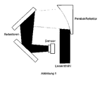
- the laser beam enters the opening of the meter.
- a parabolic reflector which deflects it in 90 ° and at the same time attenuates it.
- the attenuation is ensured by partially reflecting surfaces. Further reflectors direct the ever-decreasing beam to the sensor.
- the application targets lasers with very high powers.
- the relevant performance must be reduced to such an extent that the sensor is not damaged and is not overdriven.
- the coating of the heat sink surfaces plays the decisive role. Naked aluminum reflects almost 100%, black almost 0% of the power. In between are a few useful variants: Anodised silver : about 6% reflection Blue or red anodized: 2-3% reflection Black anodized: ⁇ 1% reflection
- the rough selection of the power class can take place through a replaceable reflector. Fine adjustment makes the electronics through adjustable gain and variable integration time. This makes it possible to realize a power range from 10W to 10kW.
- the necessary reflectors are mounted on a common heat sink, which is cooled by air or water.
- Another method is the electrical attenuation of the beam by electrical modulation.
- the light source laser
- the measured values may differ significantly from those that occur at full power.
- plexiblocks are being used, which are bombarded with short pulses. Corresponding to the beam profile, a part of the block evaporates. The remaining part of the block represents an "imprint" of the beam. The consumption of plexiblocks can therefore be very high. The resulting gases are poisonous and can cause deposits on the surrounding optical components.
Landscapes
- Physics & Mathematics (AREA)
- General Physics & Mathematics (AREA)
- Spectroscopy & Molecular Physics (AREA)
- Optics & Photonics (AREA)
- Electromagnetism (AREA)
- Lasers (AREA)
- Photometry And Measurement Of Optical Pulse Characteristics (AREA)
Abstract
Durch die Verwendung von Kühlkörpern mit speziellen Form, Ausrichtung und Oberfläche wird es möglich mit einem handelsüblichen Wärmekamera-Chip Infrarotstrahlen mit hoher Intensität (CO2 - Laser) zu analysieren. Es würde die Justage und Reparatur von Tausenden bereits installierten Laseranlagen erheblich erleichtern.
Description
- Bisher wird der Laserstrahl während der Montage/Justage durch einen einfachen Kühlkörper absorbiert, der per Luft oder Wasser gekühlt wird.
- Die Anwendung zielt in erster Linie auf Analyse von CO2-Laserstrahlen. Die Wellenlänge beträgt 10,6µm. Es eignen sich die Microbolometer Chips für diese Aufgabe. Sie sind bereits in den handelsüblichen Wärmebild-Kameras eingesetzt. Sie sind sehr empfindlich und lassen nur Energie im µW Bereich zu.
- Ein Industrielaser kann mehrere kW Leistung bringen, also die Leistung muss um mehrerer Größenordnungen verringert werden.
- Der Strahl kommt meistens mit bis zu 30-40mm Durchmesser heraus, die Sensorchips haben aber nur aktive Flächen von einigen mm Durchmesser. Ein oder mehrere Kühlkörper müssen den Strahl bündeln. Die Reflektoren sind z.B. aus Aluminium und die Oberflächen können eloxiert werden. Die scheinbar raue Fläche ist für diese Wellenlänge als Spiegel geeignet.
- Der Laserstrahl tritt in der Öffnung des Messgerätes ein. Als erstes trifft er auf einen Parabel-Refleflektor, der ihn in 90° ablenkt und gleichzeitig abschwächt. Die Abschwächung wird durch teilreflektierenden Oberflächen gewährleistet. Weitere reflektoren lenken den immer kleiner werdenden Strahl auf den Sensor.
- Bei richtiger Dimensionierung der Reflektor und deren Abstand kann eine naturgetreue, verkleinerte Abbildung des Strahl-Querschnitts erreicht werden. (siehe
Abbildung 1 ) - Die Anwendung zielt auf Laser mit sehr hohen Leistungen. Die Antreffende Leistung muss soweit vermindert werden, dass der Sensor kein Schaden nimmt und nicht übersteuert wird. Die Beschichtung der Kühlkörper-Oberflächen spielt die entscheidende Rolle. Blankes Aluminium reflektiert fast 100%, schwarze fast 0% der Leistung. Dazwischen liegen einige brauchbare Varianten:
Silber eloxiert : ca. 6% Reflexion Blau oder rot eloxiert: 2-3% Reflexion Schwarz eloxiert: < 1% Reflexion - 1 kW Leistung durch rot eloxierten Kühlkörper (3% Reflexion) abgelenkt:
1).1 kW-> (970 W Dissipation) 30W 2.)30 W-> (29,1 W Dissipation) 900 mW 3.)900mW-> (873 mW Dissipation) 27 mW 4.)27mW-> (26,19mW Dissipation) 810 µW - Die grobe Selektion der Leistungsklasse kann durch einen austauschbaren Reflektor stattfinden. Feineinstellung macht die Elektronik durch verstellbarer Verstärkung und variabler Integrationszeit. So wird es möglich einen Leistungsbereich von 10W bis 10kW zu realisieren.
- Die notwendigen Reflektoren werden auf einen gemeinsamen Kühlkörper montiert, der per Luft oder Wasser gekühlt wird.
- Bei der Strahlanalyse wird derzeit nur eine kleine Teilfläche ausgekoppelt und gemessen. Die Position dieser Teilfläche wird mechanisch verlagert. Das überwiegende Teil der Leistung muss ein separater Kühlkörper absorbieren.
- Eine weitere Methode ist die elektrische Abschwächung des Strahls durch elektrische Modulation. In diesem Fall arbeitet die Lichtquelle (Laser) nicht unter Betriebsbedingungen. Die gemessenen Werte können von denen, welche bei voller Leistung auftreten, erheblich abweichen.
- Eine optische Abschwächung durch teildurchlässige Fenster oder Linsen ist ebenfalls möglich, jedoch mit dieser Leistungsdichte sehr problematisch. Die absorbierte Leistung entsteht auf einigen mm2 oder bestenfalls auf einigen cm2. Die Abführung dieser Leistung ist sehr aufwendig.
- In der Praxis werden zurzeit Plexiblöcke eingesetzt, die mit kurzen Impulsen beschossen werden. Entsprechend des Strahlprofils verdampft ein Teil des Blocks. Der übrig gebliebene Teil des Blocks stellt einen "Abdruck" des Strahls dar. Der Verbrauch an Plexiblöcken kann also sehr hoch sein. Die entstehenden Gase sind giftig und können an den umliegenden optischen Komponenten Ablagerungen verursachen.
-
- robust
- preisgünstig
- keine bewegte Teile
- keine Verschleißteile
- Messzeit < 1 sec
- Absorbiert die volle Leistung, keine weitere Kühlkörper sind notwendig
Claims (3)
- Die Oberfläche der Kühlkörper ist nicht rechtwinklig zum Strahl ausgerichtet.
Die Reflexion hat eine vom Strahl abweichende Achse. Ein, in dieser Achse positionierter Detektor kann den Querschnitt des Strahls analysieren. - Die Oberfläche der Kühlkörper ist so gestaltet, dass ein Teil der eintreffenden Energie reflektiert wird.2.1 Farblich eloxierten Alu-Kühlkörper reflektieren einige Prozent der Energie2.2 Es können mehrere Reflektoren nacheinender den Strahl auf die gewünschte Intensität abschwächen.
- Durch eine entsprechende Krümmung der Oberfläche des Kühlkörpers kann man den reflektierten Strahl bündeln. Die Gestaltung der Oberfläche von einen oder mehreren Reflektoren ermöglicht es den Strahl zu verkleinern oder zu vergrößern bis der Strahldurchmesser mit dem Sensordurchmesser übereinstimmt
Priority Applications (1)
| Application Number | Priority Date | Filing Date | Title |
|---|---|---|---|
| EP09007968A EP2264414A1 (de) | 2009-06-18 | 2009-06-18 | Infrarot Strahlanalyse durch reflektierenden Kühlkörper |
Applications Claiming Priority (1)
| Application Number | Priority Date | Filing Date | Title |
|---|---|---|---|
| EP09007968A EP2264414A1 (de) | 2009-06-18 | 2009-06-18 | Infrarot Strahlanalyse durch reflektierenden Kühlkörper |
Publications (1)
| Publication Number | Publication Date |
|---|---|
| EP2264414A1 true EP2264414A1 (de) | 2010-12-22 |
Family
ID=41134608
Family Applications (1)
| Application Number | Title | Priority Date | Filing Date |
|---|---|---|---|
| EP09007968A Withdrawn EP2264414A1 (de) | 2009-06-18 | 2009-06-18 | Infrarot Strahlanalyse durch reflektierenden Kühlkörper |
Country Status (1)
| Country | Link |
|---|---|
| EP (1) | EP2264414A1 (de) |
Cited By (1)
| Publication number | Priority date | Publication date | Assignee | Title |
|---|---|---|---|---|
| DE102012106779A1 (de) * | 2012-07-25 | 2014-01-30 | Highyag Lasertechnologie Gmbh | Optik für Strahlvermessung |
Citations (1)
| Publication number | Priority date | Publication date | Assignee | Title |
|---|---|---|---|---|
| EP0421135A2 (de) * | 1989-10-04 | 1991-04-10 | DORRIES SCHARMANN GmbH | Verfahren und Vorrichtung zur Bestimmung der Position und des Durchmessers des Brennflecks (Fokus) eines Laserstrahls, insbesondere zur Verwendung für die Werkstoffbearbeitung mit einem Hochleistungs-Laserstrahl |
-
2009
- 2009-06-18 EP EP09007968A patent/EP2264414A1/de not_active Withdrawn
Patent Citations (1)
| Publication number | Priority date | Publication date | Assignee | Title |
|---|---|---|---|---|
| EP0421135A2 (de) * | 1989-10-04 | 1991-04-10 | DORRIES SCHARMANN GmbH | Verfahren und Vorrichtung zur Bestimmung der Position und des Durchmessers des Brennflecks (Fokus) eines Laserstrahls, insbesondere zur Verwendung für die Werkstoffbearbeitung mit einem Hochleistungs-Laserstrahl |
Non-Patent Citations (1)
| Title |
|---|
| ROACHE E ET AL: "Mirror Facets for the VERITAS Telescopes", 30TH INTERNATIONAL COSMIC RAY CONFERENCE MERIDA, YUCATAN, MEXICO,, 3 July 2007 (2007-07-03), XP007910111 * |
Cited By (2)
| Publication number | Priority date | Publication date | Assignee | Title |
|---|---|---|---|---|
| DE102012106779A1 (de) * | 2012-07-25 | 2014-01-30 | Highyag Lasertechnologie Gmbh | Optik für Strahlvermessung |
| DE102012106779B4 (de) * | 2012-07-25 | 2014-04-03 | Highyag Lasertechnologie Gmbh | Optik für Strahlvermessung |
Similar Documents
| Publication | Publication Date | Title |
|---|---|---|
| US11212512B2 (en) | System and method of imaging using multiple illumination pulses | |
| DE102012209593B4 (de) | Beleuchtungseinrichtung | |
| US6690472B2 (en) | Pulsed laser linescanner for a backscatter absorption gas imaging system | |
| EP1812913A4 (de) | Teilchendetektor, system und verfahren | |
| US11375174B2 (en) | System and method of reducing ambient background light in a pulse-illuminated image | |
| US11902494B2 (en) | System and method for glint reduction | |
| US10746875B2 (en) | Sensor system and method to operate a sensor system | |
| Mackinnon et al. | Implementation of a near backscattering imaging system on the National Ignition Facility | |
| EP2264414A1 (de) | Infrarot Strahlanalyse durch reflektierenden Kühlkörper | |
| US10458931B1 (en) | Contact imaging sensor head for computed radiography | |
| Eberle et al. | NATO SET-249 joint measurement campaign on laser dazzle effects in airborne scenarios | |
| US5604588A (en) | Imaging plasma in nonlinear limiter cells | |
| Peters et al. | Development of a novel low-cost NIR gated-viewing sensor for maritime search and rescue applications | |
| Mann et al. | Monitoring and shaping of excimer laser beam profiles | |
| WO2022040786A1 (en) | Method, system, and lighting module for fast-moving particle characterization | |
| Eetu et al. | Characterizing shockwave propagation in waveguides by Schlieren imaging | |
| US10690933B2 (en) | Speckle reduction instrument | |
| FI3821216T3 (fi) | Hyperspektrikamera | |
| Durécu et al. | Dazzling sensitivity analysis of a microbolometer array on an infrared laser irradiation breadboard | |
| US20240045069A1 (en) | Systems, methods and computer program products for generating depth images based on short-wave infrared detection information | |
| KR20140147069A (ko) | 적외선 서치 라이트 및 이를 이용한 감시 시스템 | |
| Göhler et al. | Gated viewing at 2.09 µm laser wavelength: experimental system assessment and comparison to 1.57 µm | |
| US7339972B2 (en) | Laser filament imager | |
| Churoux et al. | Model of a burst imaging lidar through the atmosphere | |
| Cohen et al. | Time-gated measurements of fusion-class laser beam profiles |
Legal Events
| Date | Code | Title | Description |
|---|---|---|---|
| PUAI | Public reference made under article 153(3) epc to a published international application that has entered the european phase |
Free format text: ORIGINAL CODE: 0009012 |
|
| AK | Designated contracting states |
Kind code of ref document: A1 Designated state(s): AT BE BG CH CY CZ DE DK EE ES FI FR GB GR HR HU IE IS IT LI LT LU LV MC MK MT NL NO PL PT RO SE SI SK TR |
|
| AX | Request for extension of the european patent |
Extension state: AL BA RS |
|
| 17P | Request for examination filed |
Effective date: 20101202 |
|
| 17Q | First examination report despatched |
Effective date: 20111213 |
|
| STAA | Information on the status of an ep patent application or granted ep patent |
Free format text: STATUS: THE APPLICATION IS DEEMED TO BE WITHDRAWN |
|
| 18D | Application deemed to be withdrawn |
Effective date: 20120424 |