EP2264313B1 - Verfahren zum Betreiben einer Windenergieanlage und Windenergieanlage - Google Patents
Verfahren zum Betreiben einer Windenergieanlage und Windenergieanlage Download PDFInfo
- Publication number
- EP2264313B1 EP2264313B1 EP10006200.9A EP10006200A EP2264313B1 EP 2264313 B1 EP2264313 B1 EP 2264313B1 EP 10006200 A EP10006200 A EP 10006200A EP 2264313 B1 EP2264313 B1 EP 2264313B1
- Authority
- EP
- European Patent Office
- Prior art keywords
- value
- wind
- boundary condition
- mass flow
- air mass
- Prior art date
- Legal status (The legal status is an assumption and is not a legal conclusion. Google has not performed a legal analysis and makes no representation as to the accuracy of the status listed.)
- Not-in-force
Links
Images

Classifications
-
- F—MECHANICAL ENGINEERING; LIGHTING; HEATING; WEAPONS; BLASTING
- F03—MACHINES OR ENGINES FOR LIQUIDS; WIND, SPRING, OR WEIGHT MOTORS; PRODUCING MECHANICAL POWER OR A REACTIVE PROPULSIVE THRUST, NOT OTHERWISE PROVIDED FOR
- F03D—WIND MOTORS
- F03D7/00—Controlling wind motors
- F03D7/02—Controlling wind motors the wind motors having rotation axis substantially parallel to the air flow entering the rotor
-
- F—MECHANICAL ENGINEERING; LIGHTING; HEATING; WEAPONS; BLASTING
- F05—INDEXING SCHEMES RELATING TO ENGINES OR PUMPS IN VARIOUS SUBCLASSES OF CLASSES F01-F04
- F05B—INDEXING SCHEME RELATING TO WIND, SPRING, WEIGHT, INERTIA OR LIKE MOTORS, TO MACHINES OR ENGINES FOR LIQUIDS COVERED BY SUBCLASSES F03B, F03D AND F03G
- F05B2260/00—Function
- F05B2260/70—Adjusting of angle of incidence or attack of rotating blades
- F05B2260/71—Adjusting of angle of incidence or attack of rotating blades as a function of flow velocity
-
- F—MECHANICAL ENGINEERING; LIGHTING; HEATING; WEAPONS; BLASTING
- F05—INDEXING SCHEMES RELATING TO ENGINES OR PUMPS IN VARIOUS SUBCLASSES OF CLASSES F01-F04
- F05B—INDEXING SCHEME RELATING TO WIND, SPRING, WEIGHT, INERTIA OR LIKE MOTORS, TO MACHINES OR ENGINES FOR LIQUIDS COVERED BY SUBCLASSES F03B, F03D AND F03G
- F05B2260/00—Function
- F05B2260/70—Adjusting of angle of incidence or attack of rotating blades
- F05B2260/74—Adjusting of angle of incidence or attack of rotating blades by turning around an axis perpendicular the rotor centre line
-
- F—MECHANICAL ENGINEERING; LIGHTING; HEATING; WEAPONS; BLASTING
- F05—INDEXING SCHEMES RELATING TO ENGINES OR PUMPS IN VARIOUS SUBCLASSES OF CLASSES F01-F04
- F05B—INDEXING SCHEME RELATING TO WIND, SPRING, WEIGHT, INERTIA OR LIKE MOTORS, TO MACHINES OR ENGINES FOR LIQUIDS COVERED BY SUBCLASSES F03B, F03D AND F03G
- F05B2270/00—Control
- F05B2270/10—Purpose of the control system
- F05B2270/103—Purpose of the control system to affect the output of the engine
- F05B2270/1033—Power (if explicitly mentioned)
-
- F—MECHANICAL ENGINEERING; LIGHTING; HEATING; WEAPONS; BLASTING
- F05—INDEXING SCHEMES RELATING TO ENGINES OR PUMPS IN VARIOUS SUBCLASSES OF CLASSES F01-F04
- F05B—INDEXING SCHEME RELATING TO WIND, SPRING, WEIGHT, INERTIA OR LIKE MOTORS, TO MACHINES OR ENGINES FOR LIQUIDS COVERED BY SUBCLASSES F03B, F03D AND F03G
- F05B2270/00—Control
- F05B2270/30—Control parameters, e.g. input parameters
- F05B2270/32—Wind speeds
- F05B2270/3201—"cut-off" or "shut-down" wind speed
-
- F—MECHANICAL ENGINEERING; LIGHTING; HEATING; WEAPONS; BLASTING
- F05—INDEXING SCHEMES RELATING TO ENGINES OR PUMPS IN VARIOUS SUBCLASSES OF CLASSES F01-F04
- F05B—INDEXING SCHEME RELATING TO WIND, SPRING, WEIGHT, INERTIA OR LIKE MOTORS, TO MACHINES OR ENGINES FOR LIQUIDS COVERED BY SUBCLASSES F03B, F03D AND F03G
- F05B2270/00—Control
- F05B2270/30—Control parameters, e.g. input parameters
- F05B2270/325—Air temperature
-
- Y—GENERAL TAGGING OF NEW TECHNOLOGICAL DEVELOPMENTS; GENERAL TAGGING OF CROSS-SECTIONAL TECHNOLOGIES SPANNING OVER SEVERAL SECTIONS OF THE IPC; TECHNICAL SUBJECTS COVERED BY FORMER USPC CROSS-REFERENCE ART COLLECTIONS [XRACs] AND DIGESTS
- Y02—TECHNOLOGIES OR APPLICATIONS FOR MITIGATION OR ADAPTATION AGAINST CLIMATE CHANGE
- Y02E—REDUCTION OF GREENHOUSE GAS [GHG] EMISSIONS, RELATED TO ENERGY GENERATION, TRANSMISSION OR DISTRIBUTION
- Y02E10/00—Energy generation through renewable energy sources
- Y02E10/70—Wind energy
- Y02E10/72—Wind turbines with rotation axis in wind direction
Definitions
- the invention relates to a method for operating a wind energy plant, in which a meteorological measured value is detected and, taking into account the measured value, a desired value for plant operation is selected, an operating state is selected and / or a boundary condition for plant operation is determined, and a wind energy plant for carrying out the method.
- the meteorological measured value central to the operation of a wind turbine is the wind speed.
- the wind speed is measured, for example, by a tray anemometer.
- the choice of an operating state as a function of the wind speed for example, a shutdown of the wind turbine above a Abschaltwind für, for example, under adjustment of the Blatteinstellwinkels in flag position.
- a meteorological measured value is recorded and, taking into account the measured value, a setpoint for the plant operation predetermined, selected an operating condition and / or determines a boundary condition for the plant operation, wherein the measured value is a wind mass flow caused by the wind.
- the invention is based on the recognition that the consideration of a wind mass flow caused by the wind can improve and simplify the control of the wind turbine in several respects.
- the air density can be taken into account implicitly without it having to be recorded as a separate measured value.
- the fundamental importance of the air mass flow for the operation of a wind energy plant is also apparent from the following consideration.
- the measurement of an air mass flow is widespread industrially, in particular it is used in the control of internal combustion engines, for example in automobiles. As a result, the process can possibly be carried out with less effort than a separate measurement of the air density.
- Another advantage is that when measuring the air mass flow, the actual air density can be detected.
- the measurement of the air density is not readily possible and is often approximated by measuring the air pressure. If necessary, a measured air temperature can also be taken into account when determining the air density, which allows a more accurate determination of the air density.
- air humidity also has a further influence on the air density, which, if necessary, must be measured separately to determine the air density.
- the consideration of the air mass flow according to the invention takes place within the operational management of the wind energy plant, which controls and regulates the components of the wind energy plant.
- the management can, for example, specify a generator torque, control a pitch angle controller, etc. That the Air mass flow is taken into account, may in particular mean that it flows into a mathematical calculation of an operating variable, or that upon reaching, falling below or exceeding defined limits of the air mass flow, an operating variable is adjusted.
- the measured value for the air mass flow caused by the wind is provided to the management.
- the actual measurand may e.g. the power consumption of a constant temperature controlled heating element, such as a hot wire, be arranged in the air flow.
- This measurand is a direct measure of the air mass flow. This measuring principle is known from industrially used hot-wire or hot-film air-mass sensors.
- a detection of the measured value for the air mass flow within a suitable air mass sensor by combining a plurality of measured variables, in particular for an air volume flow or a flow velocity, an air temperature, an air pressure and possibly an air humidity, for example based on stored in the air mass sensor curves or by calculation within the air mass sensor. This can be done for example with a so-called Karman vortex air mass sensor in which the flow rate is determined by means of ultrasonic Doppler anemometry.
- the management of the wind energy plant is ultimately provided a single measured value, which represents the air mass flow.
- the measured value can, for example, be in the unit kg / h or converted into it by applying a constant numerical factor.
- the measured value is always related to a defined area. This can be the area through which the airflow caused by the wind is measured flows through, or any other defined reference, for example, an area of 1 cm 2 .
- the air flow and the cross-sectional area used for the detection of the measured value can be limited for measuring purposes, for example by a pipe.
- the selection of an operating state can consist, for example, of switching off the wind power plant or putting it into spinning mode.
- This choice of operating mode can be made taking into account the air mass flow, for example, a certain operating mode can be selected from a certain air mass flow.
- the setpoint is a generator torque.
- the generator torque counteracts, possibly via a gear, the torque absorbed by the rotor from the wind.
- An optimum setpoint for the generator torque can therefore be specified, given the relationship given in Equation 4, taking into account the air mass flow ⁇ .
- the setpoint for the generator torque can be lowered from an average mass air flow.
- the desired value is an electrical power.
- the electrical power that can be provided by the wind turbine is according to Equation 5 developed above with the mass air flow correlated.
- An optimum setpoint for the electrical power can therefore be specified in particular taking into account the air mass flow. For example, the setpoint for the electrical power can be lowered from an average mass air flow.
- the boundary condition relates to a maximum permissible value of a load attributable to the wind.
- Wind load-related components of the wind turbine such as the rotor blades, are linked to the air mass flow because of Equation 4. It makes sense, the boundary condition, such as a maximum rotor speed, therefore, determined taking into account the air mass flow.
- the constraint is a turn-off wind speed.
- the wind turbine can be switched off or put into another operating state.
- a shutdown wind speed determined taking into account the air mass flow can more accurately reflect the actual loads which make the shutdown of the wind turbine system necessary than a fixed predetermined turn-off wind speed.
- a selection of the switch-off wind speed, which reflects the actual loads even more accurately is possible than with an additional consideration of the air density, such as DE 198 44 258 A1 known. The reason for this is that the air density considered in the known method often only approximates the actual air density, while in the measurement according to the invention of the air mass flow due to the measuring principle, it is always possible to take into account the actually present air density.
- the constraint is an on-wind speed.
- the switch-on wind speed is that wind speed at which the wind turbine is switched to the grid and put into production operation.
- the goal is to start the production operation of the wind turbine, as soon as this is economically possible.
- the air mass flow it is possible to assess more reliably whether a production operation is economically possible. For example, the production operation can already be recorded at a lower wind speed, if a relatively high air mass flow is already associated with this low wind speed due to a high air density. As a result, a better overall utilization of the wind supply is possible.
- the specification of the desired value or the determination of the boundary condition takes place on the basis of a characteristic curve which assigns to each value of the product of wind speed and air mass flow a desired value or a value for the boundary condition.
- the air mass flow can be taken into account by the operation management of the wind power plant in any manner, for example by calculating a setpoint based on a mathematical formula.
- the characteristic can be stored in a defined memory area of a computer which is evaluated by the management.
- the specification of the desired value or the determination of the boundary condition on the basis of the characteristic curve can then take place in that the operational management within the framework of a computer program forms the product of a measured wind speed and the measured air mass flow and determined by evaluation of the stored characteristic of this product associated setpoint or the value for the boundary condition and used for further plant operation.
- Deposition of a characteristic which is based on the product of wind speed and air mass flow is particularly expedient because, as can be seen from equation 4, there is a linear relationship between this product and the occurring forces.
- the specification of the desired value or the determination of the boundary condition takes place on the basis of a characteristic curve which assigns to each value of the product of rotor or generator speed and air mass flow a desired value or a value for the boundary condition.
- the characteristic thus defined is particularly useful for specifying a setpoint for the generator torque in partial load operation.
- Equation 6 The air density ⁇ air can in turn be eliminated by combining Equation 6 with Equation 3, resulting in the following expression for the generator torque:
- M gene c p ⁇ ⁇ ⁇ R 4 2 ⁇ ⁇ 2 ⁇ A LM ⁇ ⁇ ⁇ m ⁇
- This formula shows the proportionality of the generator torque to be specified to the product of rotor speed and air mass flow.
- the wind energy plant according to the invention has a rotor, which has at least one rotor blade, a generator, a device for detecting a meteorological measured value and an operational management, wherein the operational management is designed such that it sets a target value for the plant operation, taking into account the measured value, selects an operating state and / or determines a boundary condition for the plant operation, wherein the means for detecting the measured value is an air mass sensor for detecting a wind mass flow caused by the wind.
- the wind turbine is suitable for carrying out the method.
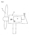
- Fig. 1 shows a wind turbine with a rotor 10 having at least one rotor blade, and a nacelle 12, in which a non-illustrated generator is arranged, which is driven by the rotor 10.
- the wind energy plant has an operation guide 14, which controls the wind energy plant.
- the operation guide 14 is connected to an air mass sensor 16 which provides the operation guide 14 with a measurement of the mass air flow passing through a defined area caused by the wind.
- the operating management 14, taking into account the measured value for the air mass flow, a setpoint 18 for the operation of the system, for example, a generator torque.
- the operating control 14 determines a boundary condition 20 taking into account the measured value for the air mass flow. This is, for example, a switch-off wind speed.
- Fig. 2 shows a load of a component of the wind turbine, such as a rotor blade, depending on the wind speed.
- the curve 30 shows the load at a first air density ⁇ 1 , the curve 32 at a second air density ⁇ 2 .
- the air density ⁇ 2 is greater than the air density ⁇ 1 , so that also the load associated with the curve 32 of a certain wind speed ⁇ is higher than that of the curve 30. Since the load basically increases quadratically with the wind speed, the curves 30 and 32 show the typical course of a quadratic function.
- Fig. 3 is the load not on the wind speed v, but on the product of the wind speed v and the air mass flow ⁇ applied.
- a single curve 34 results that applies equally to different airtightnesses.
- the curve 34 is a straight line.
Landscapes
- Engineering & Computer Science (AREA)
- Life Sciences & Earth Sciences (AREA)
- Sustainable Development (AREA)
- Sustainable Energy (AREA)
- Chemical & Material Sciences (AREA)
- Combustion & Propulsion (AREA)
- Mechanical Engineering (AREA)
- General Engineering & Computer Science (AREA)
- Wind Motors (AREA)
Priority Applications (1)
| Application Number | Priority Date | Filing Date | Title |
|---|---|---|---|
| PL10006200T PL2264313T3 (pl) | 2009-06-18 | 2010-06-15 | Sposób eksploatacji turbiny wiatrowej oraz turbina wiatrowa |
Applications Claiming Priority (1)
| Application Number | Priority Date | Filing Date | Title |
|---|---|---|---|
| DE102009025445A DE102009025445B3 (de) | 2009-06-18 | 2009-06-18 | Verfahren zum Betreiben einer Windenergieanlage und Windenergieanlage zur Ausführung des Verfahrens |
Publications (3)
| Publication Number | Publication Date |
|---|---|
| EP2264313A2 EP2264313A2 (de) | 2010-12-22 |
| EP2264313A3 EP2264313A3 (de) | 2014-03-05 |
| EP2264313B1 true EP2264313B1 (de) | 2015-07-29 |
Family
ID=42551688
Family Applications (1)
| Application Number | Title | Priority Date | Filing Date |
|---|---|---|---|
| EP10006200.9A Not-in-force EP2264313B1 (de) | 2009-06-18 | 2010-06-15 | Verfahren zum Betreiben einer Windenergieanlage und Windenergieanlage |
Country Status (5)
| Country | Link |
|---|---|
| US (1) | US8386085B2 (pl) |
| EP (1) | EP2264313B1 (pl) |
| DE (1) | DE102009025445B3 (pl) |
| DK (1) | DK2264313T3 (pl) |
| PL (1) | PL2264313T3 (pl) |
Cited By (1)
| Publication number | Priority date | Publication date | Assignee | Title |
|---|---|---|---|---|
| DE102016124703A1 (de) | 2016-12-16 | 2018-06-21 | Wobben Properties Gmbh | Verfahren zum Betrieb einer Windenergieanlage sowie Einrichtung zum Steuern und/oder Regeln einer Windenergieanlage und entsprechende Windenergieanlage mit einem Rotor und einem über den Rotor angetriebenen Generator zur Erzeugung einer elektrischen Leistung |
Families Citing this family (13)
| Publication number | Priority date | Publication date | Assignee | Title |
|---|---|---|---|---|
| DE102010054013A1 (de) | 2010-12-10 | 2012-06-14 | Nordex Energy Gmbh | Verfahren zum Betrieb einer pitchgeregelten Windenergieanlage |
| DE102010054014A1 (de) * | 2010-12-10 | 2012-06-14 | Nordex Energy Gmbh | Verfahren zum Betrieb einer pitchgeregelten Windenergieanlage |
| DE102011101897A1 (de) * | 2011-05-18 | 2012-11-22 | Nordex Energy Gmbh | Verfahren zum Betreiben einer Windenergieanlage |
| ES2398027B1 (es) | 2011-05-24 | 2014-09-05 | Gamesa Innovation & Technology, S.L. | Métodos y sistemas de control de aerogeneradores en condiciones de clima frio y baja altitud. |
| US20130003071A1 (en) * | 2011-06-30 | 2013-01-03 | Catch the Wind, Inc. | System and Method of In Situ Wind Turbine Blade Monitoring |
| EP2584193A1 (en) * | 2011-10-20 | 2013-04-24 | Siemens Aktiengesellschaft | Wind turbine with air density correction of pitch angle |
| US9404478B2 (en) * | 2012-04-24 | 2016-08-02 | General Electric Company | Methods and systems for operating a wind turbine in noise reduced operation modes |
| EP2840257B1 (en) * | 2013-08-23 | 2018-04-04 | Alstom Renovables España, S.L. | Method of determining a cut-in wind speed |
| US9920742B2 (en) | 2014-02-20 | 2018-03-20 | General Electric Company | Dynamic cut-in wind speed for wind turbines |
| CN105631126B (zh) * | 2015-12-28 | 2018-08-24 | 中国电建集团成都勘测设计研究院有限公司 | 一种生成原型水轮机运转综合特性曲线的方法 |
| DE102016110190A1 (de) * | 2016-06-02 | 2017-12-07 | Wobben Properties Gmbh | Verfahren zum Steuern einer Windenergieanlage und Windenergieanlage |
| DE102016015133A1 (de) | 2016-12-13 | 2018-06-14 | Senvion Gmbh | Windenergieanlage und Verfahren zum Starten einer Windenergieanlage |
| EP3489507B1 (de) * | 2017-11-28 | 2023-04-26 | Nordex Energy SE & Co. KG | Verfahren und vorrichtung zum betreiben einer windenergieanlage |
Family Cites Families (10)
| Publication number | Priority date | Publication date | Assignee | Title |
|---|---|---|---|---|
| US4333018A (en) * | 1977-11-21 | 1982-06-01 | Ventus Energy Corp. | Wind energy conversion system with reaction torque for power control |
| US4355955A (en) * | 1981-04-06 | 1982-10-26 | The Boeing Company | Wind turbine rotor speed control system |
| DE19844258A1 (de) * | 1998-09-26 | 2000-03-30 | Dewind Technik Gmbh | Windenergieanlage |
| JP3465246B2 (ja) * | 2001-11-08 | 2003-11-10 | 学校法人東海大学 | 流体発電装置 |
| US7317260B2 (en) * | 2004-05-11 | 2008-01-08 | Clipper Windpower Technology, Inc. | Wind flow estimation and tracking using tower dynamics |
| EP1596062B1 (de) * | 2004-05-14 | 2012-05-02 | Flytec AG | Flügelrad |
| IL165233A (en) * | 2004-11-16 | 2013-06-27 | Israel Hirshberg | Energy conversion facility |
| DE102006032007A1 (de) * | 2006-07-10 | 2008-01-24 | Patent-Treuhand-Gesellschaft für elektrische Glühlampen mbH | Energieumwandler-Modul und Leucht-Vorrichtung |
| US8183707B2 (en) * | 2007-10-30 | 2012-05-22 | General Electric Company | Method of controlling a wind energy system and wind speed sensor free wind energy system |
| US7999406B2 (en) * | 2008-02-29 | 2011-08-16 | General Electric Company | Wind turbine plant high wind derating control |
-
2009
- 2009-06-18 DE DE102009025445A patent/DE102009025445B3/de not_active Expired - Fee Related
- 2009-08-21 US US12/545,492 patent/US8386085B2/en not_active Expired - Fee Related
-
2010
- 2010-06-15 EP EP10006200.9A patent/EP2264313B1/de not_active Not-in-force
- 2010-06-15 PL PL10006200T patent/PL2264313T3/pl unknown
- 2010-06-15 DK DK10006200.9T patent/DK2264313T3/en active
Cited By (2)
| Publication number | Priority date | Publication date | Assignee | Title |
|---|---|---|---|---|
| DE102016124703A1 (de) | 2016-12-16 | 2018-06-21 | Wobben Properties Gmbh | Verfahren zum Betrieb einer Windenergieanlage sowie Einrichtung zum Steuern und/oder Regeln einer Windenergieanlage und entsprechende Windenergieanlage mit einem Rotor und einem über den Rotor angetriebenen Generator zur Erzeugung einer elektrischen Leistung |
| WO2018109100A1 (de) | 2016-12-16 | 2018-06-21 | Wobben Properties Gmbh | Verfahren zum betrieb einer windenergieanlage sowie einrichtung zum steuern und/oder regeln einer windenergieanlage und entsprechende windenergieanlage mit einem rotor und einem über den rotor angetriebenen generator zur erzeugung einer elektrischen leistung |
Also Published As
| Publication number | Publication date |
|---|---|
| PL2264313T3 (pl) | 2015-12-31 |
| US20100320761A1 (en) | 2010-12-23 |
| US8386085B2 (en) | 2013-02-26 |
| DE102009025445B3 (de) | 2010-09-23 |
| EP2264313A3 (de) | 2014-03-05 |
| DK2264313T3 (en) | 2015-11-02 |
| EP2264313A2 (de) | 2010-12-22 |
Similar Documents
| Publication | Publication Date | Title |
|---|---|---|
| EP2264313B1 (de) | Verfahren zum Betreiben einer Windenergieanlage und Windenergieanlage | |
| EP2112373B1 (de) | Verfahren zum Betreiben einer Windenergieanlage | |
| EP2861867B1 (de) | Windenergieanlage und verfahren zum steuern einer windenergieanlage oder eines windparks | |
| EP1923568B1 (de) | Verfahren zum Betrieb einer Windenergieanlage im leistungslimitiertenen Betrieb | |
| DE102011052666B4 (de) | Vorrichtung und Verfahren zum Betreiben einer Windkraftanlage | |
| EP3420226B1 (de) | Verfahren zum bestimmen einer äquivalenten windgeschwindigkeit | |
| DE102004056255B4 (de) | Verfahren zur Optimierung von Betriebsparametern bei Windenergieanlagen | |
| EP2028369B1 (de) | Verfahren und Vorrichtung zum Bestimmen einer Kennlinie für eine elektrische Größe einer Windenergieanlage | |
| EP2758659B1 (de) | Verfahren zum betrieb einer windenergieanlage | |
| EP3938651B1 (de) | Verfahren zum erkennen eines eisansatzes an einer windenergieanlage | |
| EP2998573B1 (de) | Verfahren zum Betreiben einer Windenergieanlage mit einer Rotorblattheizeinrichtung | |
| EP3555461B1 (de) | Verfahren zum betrieb einer windenergieanlage sowie einrichtung zum steuern und/oder regeln einer windenergieanlage und entsprechende windenergieanlage mit einem rotor und einem über den rotor angetriebenen generator zur erzeugung einer elektrischen leistung | |
| WO2018104299A1 (de) | Windenergieanlage und verfahren zum betreiben einer windenergieanlage | |
| EP3740674B1 (de) | Verfahren zum steuern einer windenergieanlage und windenergieanlage | |
| DE102017131241B4 (de) | Überwachungsverfahren für eine Windkraftanlage, zugehörige Überwachungsvorrichtung sowie Windkraftanlage mit Überwachungsvorrichtung | |
| EP2014916A2 (de) | Verfahren und Vorrichtung zur Ermittlung einer Belastung einer Windenergieanlage | |
| WO2023170138A1 (de) | Brennstoffzellensystem, fahrzeug, verfahren zum steuern einer brennstoffzellenanordnung und computerprogrammprodukt | |
| EP3495656B1 (de) | Verfahren zur bestimmung der belastungsdynamik einer windenergieanlage | |
| DE4231303A1 (de) | Vorrichtung zum feststellen der vereisung der rotorblaetter eines luftfahrzeuges | |
| EP4116576B1 (de) | Verfahren zum erkennen einer extremlast an einer windenergieanlage | |
| EP3768970A1 (de) | Verfahren zum betreiben einer windenergieanlage, windenergieanlage und windpark | |
| EP4671535A1 (de) | Verfahren zum validieren einer windenergieanlage | |
| DE102018007997A1 (de) | Verfahren und System zum Betreiben einer Windenergieanlage | |
| DE102010054632A1 (de) | Verfahren und Vorrichtung zur Steuerung eines Triebstrangs einer Windkraftanlage |
Legal Events
| Date | Code | Title | Description |
|---|---|---|---|
| PUAI | Public reference made under article 153(3) epc to a published international application that has entered the european phase |
Free format text: ORIGINAL CODE: 0009012 |
|
| AK | Designated contracting states |
Kind code of ref document: A2 Designated state(s): AL AT BE BG CH CY CZ DE DK EE ES FI FR GB GR HR HU IE IS IT LI LT LU LV MC MK MT NL NO PL PT RO SE SI SK SM TR |
|
| AX | Request for extension of the european patent |
Extension state: BA ME RS |
|
| PUAL | Search report despatched |
Free format text: ORIGINAL CODE: 0009013 |
|
| AK | Designated contracting states |
Kind code of ref document: A3 Designated state(s): AL AT BE BG CH CY CZ DE DK EE ES FI FR GB GR HR HU IE IS IT LI LT LU LV MC MK MT NL NO PL PT RO SE SI SK SM TR |
|
| AX | Request for extension of the european patent |
Extension state: BA ME RS |
|
| RIC1 | Information provided on ipc code assigned before grant |
Ipc: F03D 7/02 20060101AFI20140130BHEP |
|
| 17P | Request for examination filed |
Effective date: 20140902 |
|
| RBV | Designated contracting states (corrected) |
Designated state(s): AL AT BE BG CH CY CZ DE DK EE ES FI FR GB GR HR HU IE IS IT LI LT LU LV MC MK MT NL NO PL PT RO SE SI SK SM TR |
|
| GRAP | Despatch of communication of intention to grant a patent |
Free format text: ORIGINAL CODE: EPIDOSNIGR1 |
|
| INTG | Intention to grant announced |
Effective date: 20150213 |
|
| GRAS | Grant fee paid |
Free format text: ORIGINAL CODE: EPIDOSNIGR3 |
|
| GRAA | (expected) grant |
Free format text: ORIGINAL CODE: 0009210 |
|
| AK | Designated contracting states |
Kind code of ref document: B1 Designated state(s): AL AT BE BG CH CY CZ DE DK EE ES FI FR GB GR HR HU IE IS IT LI LT LU LV MC MK MT NL NO PL PT RO SE SI SK SM TR |
|
| RAP1 | Party data changed (applicant data changed or rights of an application transferred) |
Owner name: NORDEX ENERGY GMBH |
|
| REG | Reference to a national code |
Ref country code: GB Ref legal event code: FG4D Free format text: NOT ENGLISH |
|
| REG | Reference to a national code |
Ref country code: CH Ref legal event code: EP |
|
| REG | Reference to a national code |
Ref country code: AT Ref legal event code: REF Ref document number: 739523 Country of ref document: AT Kind code of ref document: T Effective date: 20150815 |
|
| REG | Reference to a national code |
Ref country code: IE Ref legal event code: FG4D Free format text: LANGUAGE OF EP DOCUMENT: GERMAN |
|
| REG | Reference to a national code |
Ref country code: DE Ref legal event code: R096 Ref document number: 502010009912 Country of ref document: DE |
|
| REG | Reference to a national code |
Ref country code: DK Ref legal event code: T3 Effective date: 20151030 |
|
| REG | Reference to a national code |
Ref country code: SE Ref legal event code: TRGR |
|
| REG | Reference to a national code |
Ref country code: LT Ref legal event code: MG4D |
|
| REG | Reference to a national code |
Ref country code: PL Ref legal event code: T3 |
|
| REG | Reference to a national code |
Ref country code: NL Ref legal event code: MP Effective date: 20150729 |
|
| PG25 | Lapsed in a contracting state [announced via postgrant information from national office to epo] |
Ref country code: NO Free format text: LAPSE BECAUSE OF FAILURE TO SUBMIT A TRANSLATION OF THE DESCRIPTION OR TO PAY THE FEE WITHIN THE PRESCRIBED TIME-LIMIT Effective date: 20151029 Ref country code: LV Free format text: LAPSE BECAUSE OF FAILURE TO SUBMIT A TRANSLATION OF THE DESCRIPTION OR TO PAY THE FEE WITHIN THE PRESCRIBED TIME-LIMIT Effective date: 20150729 Ref country code: FI Free format text: LAPSE BECAUSE OF FAILURE TO SUBMIT A TRANSLATION OF THE DESCRIPTION OR TO PAY THE FEE WITHIN THE PRESCRIBED TIME-LIMIT Effective date: 20150729 Ref country code: LT Free format text: LAPSE BECAUSE OF FAILURE TO SUBMIT A TRANSLATION OF THE DESCRIPTION OR TO PAY THE FEE WITHIN THE PRESCRIBED TIME-LIMIT Effective date: 20150729 Ref country code: GR Free format text: LAPSE BECAUSE OF FAILURE TO SUBMIT A TRANSLATION OF THE DESCRIPTION OR TO PAY THE FEE WITHIN THE PRESCRIBED TIME-LIMIT Effective date: 20151030 |
|
| PG25 | Lapsed in a contracting state [announced via postgrant information from national office to epo] |
Ref country code: PT Free format text: LAPSE BECAUSE OF FAILURE TO SUBMIT A TRANSLATION OF THE DESCRIPTION OR TO PAY THE FEE WITHIN THE PRESCRIBED TIME-LIMIT Effective date: 20151130 Ref country code: IS Free format text: LAPSE BECAUSE OF FAILURE TO SUBMIT A TRANSLATION OF THE DESCRIPTION OR TO PAY THE FEE WITHIN THE PRESCRIBED TIME-LIMIT Effective date: 20151129 Ref country code: ES Free format text: LAPSE BECAUSE OF FAILURE TO SUBMIT A TRANSLATION OF THE DESCRIPTION OR TO PAY THE FEE WITHIN THE PRESCRIBED TIME-LIMIT Effective date: 20150729 Ref country code: HR Free format text: LAPSE BECAUSE OF FAILURE TO SUBMIT A TRANSLATION OF THE DESCRIPTION OR TO PAY THE FEE WITHIN THE PRESCRIBED TIME-LIMIT Effective date: 20150729 |
|
| PG25 | Lapsed in a contracting state [announced via postgrant information from national office to epo] |
Ref country code: NL Free format text: LAPSE BECAUSE OF FAILURE TO SUBMIT A TRANSLATION OF THE DESCRIPTION OR TO PAY THE FEE WITHIN THE PRESCRIBED TIME-LIMIT Effective date: 20150729 |
|
| PG25 | Lapsed in a contracting state [announced via postgrant information from national office to epo] |
Ref country code: EE Free format text: LAPSE BECAUSE OF FAILURE TO SUBMIT A TRANSLATION OF THE DESCRIPTION OR TO PAY THE FEE WITHIN THE PRESCRIBED TIME-LIMIT Effective date: 20150729 Ref country code: CZ Free format text: LAPSE BECAUSE OF FAILURE TO SUBMIT A TRANSLATION OF THE DESCRIPTION OR TO PAY THE FEE WITHIN THE PRESCRIBED TIME-LIMIT Effective date: 20150729 Ref country code: SK Free format text: LAPSE BECAUSE OF FAILURE TO SUBMIT A TRANSLATION OF THE DESCRIPTION OR TO PAY THE FEE WITHIN THE PRESCRIBED TIME-LIMIT Effective date: 20150729 Ref country code: IT Free format text: LAPSE BECAUSE OF FAILURE TO SUBMIT A TRANSLATION OF THE DESCRIPTION OR TO PAY THE FEE WITHIN THE PRESCRIBED TIME-LIMIT Effective date: 20150729 |
|
| REG | Reference to a national code |
Ref country code: DE Ref legal event code: R097 Ref document number: 502010009912 Country of ref document: DE |
|
| PG25 | Lapsed in a contracting state [announced via postgrant information from national office to epo] |
Ref country code: RO Free format text: LAPSE BECAUSE OF FAILURE TO SUBMIT A TRANSLATION OF THE DESCRIPTION OR TO PAY THE FEE WITHIN THE PRESCRIBED TIME-LIMIT Effective date: 20150729 |
|
| PLBE | No opposition filed within time limit |
Free format text: ORIGINAL CODE: 0009261 |
|
| STAA | Information on the status of an ep patent application or granted ep patent |
Free format text: STATUS: NO OPPOSITION FILED WITHIN TIME LIMIT |
|
| REG | Reference to a national code |
Ref country code: FR Ref legal event code: PLFP Year of fee payment: 7 |
|
| 26N | No opposition filed |
Effective date: 20160502 |
|
| PG25 | Lapsed in a contracting state [announced via postgrant information from national office to epo] |
Ref country code: SI Free format text: LAPSE BECAUSE OF FAILURE TO SUBMIT A TRANSLATION OF THE DESCRIPTION OR TO PAY THE FEE WITHIN THE PRESCRIBED TIME-LIMIT Effective date: 20150729 |
|
| PG25 | Lapsed in a contracting state [announced via postgrant information from national office to epo] |
Ref country code: BE Free format text: LAPSE BECAUSE OF NON-PAYMENT OF DUE FEES Effective date: 20160630 |
|
| PG25 | Lapsed in a contracting state [announced via postgrant information from national office to epo] |
Ref country code: MC Free format text: LAPSE BECAUSE OF FAILURE TO SUBMIT A TRANSLATION OF THE DESCRIPTION OR TO PAY THE FEE WITHIN THE PRESCRIBED TIME-LIMIT Effective date: 20150729 |
|
| REG | Reference to a national code |
Ref country code: CH Ref legal event code: PL |
|
| PG25 | Lapsed in a contracting state [announced via postgrant information from national office to epo] |
Ref country code: CH Free format text: LAPSE BECAUSE OF NON-PAYMENT OF DUE FEES Effective date: 20160630 Ref country code: LI Free format text: LAPSE BECAUSE OF NON-PAYMENT OF DUE FEES Effective date: 20160630 |
|
| REG | Reference to a national code |
Ref country code: FR Ref legal event code: PLFP Year of fee payment: 8 |
|
| PGFP | Annual fee paid to national office [announced via postgrant information from national office to epo] |
Ref country code: FR Payment date: 20170724 Year of fee payment: 12 Ref country code: IE Payment date: 20170622 Year of fee payment: 8 |
|
| REG | Reference to a national code |
Ref country code: AT Ref legal event code: MM01 Ref document number: 739523 Country of ref document: AT Kind code of ref document: T Effective date: 20160615 |
|
| PGFP | Annual fee paid to national office [announced via postgrant information from national office to epo] |
Ref country code: PL Payment date: 20170509 Year of fee payment: 8 Ref country code: SE Payment date: 20170626 Year of fee payment: 8 |
|
| PGFP | Annual fee paid to national office [announced via postgrant information from national office to epo] |
Ref country code: TR Payment date: 20170608 Year of fee payment: 8 |
|
| PG25 | Lapsed in a contracting state [announced via postgrant information from national office to epo] |
Ref country code: AT Free format text: LAPSE BECAUSE OF NON-PAYMENT OF DUE FEES Effective date: 20160615 |
|
| PG25 | Lapsed in a contracting state [announced via postgrant information from national office to epo] |
Ref country code: SM Free format text: LAPSE BECAUSE OF FAILURE TO SUBMIT A TRANSLATION OF THE DESCRIPTION OR TO PAY THE FEE WITHIN THE PRESCRIBED TIME-LIMIT Effective date: 20150729 Ref country code: CY Free format text: LAPSE BECAUSE OF FAILURE TO SUBMIT A TRANSLATION OF THE DESCRIPTION OR TO PAY THE FEE WITHIN THE PRESCRIBED TIME-LIMIT Effective date: 20150729 Ref country code: HU Free format text: LAPSE BECAUSE OF FAILURE TO SUBMIT A TRANSLATION OF THE DESCRIPTION OR TO PAY THE FEE WITHIN THE PRESCRIBED TIME-LIMIT; INVALID AB INITIO Effective date: 20100615 |
|
| PG25 | Lapsed in a contracting state [announced via postgrant information from national office to epo] |
Ref country code: LU Free format text: LAPSE BECAUSE OF NON-PAYMENT OF DUE FEES Effective date: 20160615 Ref country code: MK Free format text: LAPSE BECAUSE OF FAILURE TO SUBMIT A TRANSLATION OF THE DESCRIPTION OR TO PAY THE FEE WITHIN THE PRESCRIBED TIME-LIMIT Effective date: 20150729 Ref country code: MT Free format text: LAPSE BECAUSE OF FAILURE TO SUBMIT A TRANSLATION OF THE DESCRIPTION OR TO PAY THE FEE WITHIN THE PRESCRIBED TIME-LIMIT Effective date: 20150729 |
|
| PG25 | Lapsed in a contracting state [announced via postgrant information from national office to epo] |
Ref country code: BG Free format text: LAPSE BECAUSE OF FAILURE TO SUBMIT A TRANSLATION OF THE DESCRIPTION OR TO PAY THE FEE WITHIN THE PRESCRIBED TIME-LIMIT Effective date: 20150729 |
|
| PG25 | Lapsed in a contracting state [announced via postgrant information from national office to epo] |
Ref country code: AL Free format text: LAPSE BECAUSE OF FAILURE TO SUBMIT A TRANSLATION OF THE DESCRIPTION OR TO PAY THE FEE WITHIN THE PRESCRIBED TIME-LIMIT Effective date: 20150729 |
|
| REG | Reference to a national code |
Ref country code: SE Ref legal event code: EUG |
|
| PG25 | Lapsed in a contracting state [announced via postgrant information from national office to epo] |
Ref country code: SE Free format text: LAPSE BECAUSE OF NON-PAYMENT OF DUE FEES Effective date: 20180616 |
|
| REG | Reference to a national code |
Ref country code: IE Ref legal event code: MM4A |
|
| PG25 | Lapsed in a contracting state [announced via postgrant information from national office to epo] |
Ref country code: FR Free format text: LAPSE BECAUSE OF NON-PAYMENT OF DUE FEES Effective date: 20180630 Ref country code: IE Free format text: LAPSE BECAUSE OF NON-PAYMENT OF DUE FEES Effective date: 20180615 |
|
| PGFP | Annual fee paid to national office [announced via postgrant information from national office to epo] |
Ref country code: DK Payment date: 20190624 Year of fee payment: 10 |
|
| PGFP | Annual fee paid to national office [announced via postgrant information from national office to epo] |
Ref country code: DE Payment date: 20190813 Year of fee payment: 10 Ref country code: GB Payment date: 20190624 Year of fee payment: 10 |
|
| PG25 | Lapsed in a contracting state [announced via postgrant information from national office to epo] |
Ref country code: PL Free format text: LAPSE BECAUSE OF NON-PAYMENT OF DUE FEES Effective date: 20180615 |
|
| REG | Reference to a national code |
Ref country code: DE Ref legal event code: R119 Ref document number: 502010009912 Country of ref document: DE |
|
| REG | Reference to a national code |
Ref country code: DK Ref legal event code: EBP Effective date: 20200630 |
|
| GBPC | Gb: european patent ceased through non-payment of renewal fee |
Effective date: 20200615 |
|
| PG25 | Lapsed in a contracting state [announced via postgrant information from national office to epo] |
Ref country code: GB Free format text: LAPSE BECAUSE OF NON-PAYMENT OF DUE FEES Effective date: 20200615 |
|
| PG25 | Lapsed in a contracting state [announced via postgrant information from national office to epo] |
Ref country code: DE Free format text: LAPSE BECAUSE OF NON-PAYMENT OF DUE FEES Effective date: 20210101 |
|
| PG25 | Lapsed in a contracting state [announced via postgrant information from national office to epo] |
Ref country code: DK Free format text: LAPSE BECAUSE OF NON-PAYMENT OF DUE FEES Effective date: 20200630 |
|
| PG25 | Lapsed in a contracting state [announced via postgrant information from national office to epo] |
Ref country code: TR Free format text: LAPSE BECAUSE OF NON-PAYMENT OF DUE FEES Effective date: 20180615 |