EP2264289A1 - Oil strainer for outboard motor unit - Google Patents
Oil strainer for outboard motor unit Download PDFInfo
- Publication number
- EP2264289A1 EP2264289A1 EP10250940A EP10250940A EP2264289A1 EP 2264289 A1 EP2264289 A1 EP 2264289A1 EP 10250940 A EP10250940 A EP 10250940A EP 10250940 A EP10250940 A EP 10250940A EP 2264289 A1 EP2264289 A1 EP 2264289A1
- Authority
- EP
- European Patent Office
- Prior art keywords
- oil
- strainer
- case
- seal member
- tube
- Prior art date
- Legal status (The legal status is an assumption and is not a legal conclusion. Google has not performed a legal analysis and makes no representation as to the accuracy of the status listed.)
- Granted
Links
Images



Classifications
-
- F—MECHANICAL ENGINEERING; LIGHTING; HEATING; WEAPONS; BLASTING
- F01—MACHINES OR ENGINES IN GENERAL; ENGINE PLANTS IN GENERAL; STEAM ENGINES
- F01M—LUBRICATING OF MACHINES OR ENGINES IN GENERAL; LUBRICATING INTERNAL COMBUSTION ENGINES; CRANKCASE VENTILATING
- F01M11/00—Component parts, details or accessories, not provided for in, or of interest apart from, groups F01M1/00 - F01M9/00
- F01M11/02—Arrangements of lubricant conduits
-
- F—MECHANICAL ENGINEERING; LIGHTING; HEATING; WEAPONS; BLASTING
- F01—MACHINES OR ENGINES IN GENERAL; ENGINE PLANTS IN GENERAL; STEAM ENGINES
- F01M—LUBRICATING OF MACHINES OR ENGINES IN GENERAL; LUBRICATING INTERNAL COMBUSTION ENGINES; CRANKCASE VENTILATING
- F01M11/00—Component parts, details or accessories, not provided for in, or of interest apart from, groups F01M1/00 - F01M9/00
-
- F—MECHANICAL ENGINEERING; LIGHTING; HEATING; WEAPONS; BLASTING
- F01—MACHINES OR ENGINES IN GENERAL; ENGINE PLANTS IN GENERAL; STEAM ENGINES
- F01M—LUBRICATING OF MACHINES OR ENGINES IN GENERAL; LUBRICATING INTERNAL COMBUSTION ENGINES; CRANKCASE VENTILATING
- F01M11/00—Component parts, details or accessories, not provided for in, or of interest apart from, groups F01M1/00 - F01M9/00
- F01M11/03—Mounting or connecting of lubricant purifying means relative to the machine or engine; Details of lubricant purifying means
Definitions
- This invention relates to an oil strainer housed in an outboard motor unit.
- Outboard motor units have been known in the past as apparatuses for providing propulsion force to boats and other waterborne vehicles, as disclosed, for example, in Japanese Patent Application Laid-Open Publication No. HEI-05-33779 ( JP H05-33779 A ).
- FIG. 7 hereof shows the outboard motor unit disclosed in JP H05-33779 A .
- An engine 102 covered by an engine cover 101 is provided to an upper part of the outboard motor unit 100, as shown in FIG. 7(a) .
- the outboard motor unit 100 has a stern bracket 105 and is attached to a back end 104 of a waterborne vehicle 103 via the stern bracket 105.
- the engine 102 is supported by a mount case 106.
- An oil pan 107 is attached to an underside of the mount case 106. The internal structure of the oil pan 107 is described on the basis of FIG. 7(b) .
- the oil strainer 109 is connected to the suction port 108 of an oil pump.
- the oil strainer 109 is attached to the mount case 106 via a supporting member 111.
- the oil strainer 109 disclosed in Japanese Laid-open Patent Application No. 5-33779 is integrally constructed from a strainer case 112 in which an element is housed, and an oil tube 113 for connecting the strainer case 112 and the suction port 108 of the oil pump. Therefore, the position of the strainer case 112 is fixed. It is necessary to newly prepare an oil strainer having an oil tube of a different length when the position of the strainer case 112 is changed as needed. The result is an increase in the replacement cost of oil strainers.
- an oil strainer adapted to be disposed in a suction area of an oil pump of an outboard engine unit, for filtering oil and supplying the filtered oil to the oil pump via an oil channel
- oil strainer comprises: a strainer case with a filtering element housed therein, the strainer case being provided with an oil inlet and an oil outlet; an oil tube extending from the oil outlet to an inlet of the oil channel; a first seal member fitted into one end of the oil tube and compressed at the oil outlet to operate as a seal; and a second seal member fitted into an opposite end of the oil tube and compressed at the inlet to the oil channel to operate as a seal, wherein the oil tube is supported at both ends by the first seal member and the second seal member.
- the oil tube can be easily removed from the strainer case.
- the strainer case In cases in which the situation demands that the position of the strainer case be changed, only the oil tube of a different length should be prepared, and the strainer case can be used with the new tube.
- the position of the strainer case can be changed at a lower cost compared with an oil strainer integrally constructed of a strainer case and an oil tube. Accordingly, there can be provided an oil strainer for use in an outboard motor unit wherein the position of the strainer case can be changed at a low cost.
- each of the first seal member and the second seal member comprises an O-ring.
- O-rings are readily available and inexpensive. Hence, it is possible to reduce the manufacturing cost of the oil strainer.
- the one end of the oil tube has a first stepped part for restricting axial movement of the first seal member while the opposite end of the oil tube has a second stepped part for restricting axial movement of the second seal member.
- the first seal member will not go beyond the first stepped part, and the second seal member will not go beyond the second stepped part.
- the first seal member and the second seal member remain in a predetermined area, allowing the sealing properties of the oil outlet of the strainer case and the inlet of the oil channel to be further improved.
- the strainer case include a case lower half formed of a resin material having the oil inlet, and a case upper half formed of a resin material having the oil outlet. Therefore, the strainer case can be made more lightweight compared with cases in which the two case halves are made of metal.
- the element be wedged between the case lower half and the case upper half, and be joined to the case lower half and the case upper half by a thermal welded part. Accordingly, the strainer case can be made more lightweight compared with cases in which the two case halves are integrated by bolting.
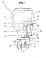
- An outboard motor unit 10 shown in FIG. 1 includes an engine cover 12 that covers an engine 11, the cover being provided to an upper part; an undercover 15 connected to a lower end of the engine cover 12 and made to extend downward while covering a lower part of the engine 11, a mount case 13, and an upper half of an oil pan 14; an extension cover 16 connected to a lower end of the undercover 15 and used to cover a lower half of the oil pan 14; and a gear case 21 connected to a lower end of the extension cover 16 and used to house a gear mechanism 18 and a drive shaft 17 linked to a crankshaft of the engine 11.
- a propeller 19 is rotated via the gear mechanism 18 and the drive shaft 17 by the running of the engine 11.
- the outboard motor unit 10 is provided with a stern bracket 24 attached to a back end 23 of a boat or other waterborne vehicle 22, a swivel case 25 rotatably attached to the stern bracket 24, a backwardly extending mount frame 27 supporting the mount case 13 and having a swivel shaft 26 rotatably inserted into the swivel case 25, and a backwardly extending lower mount center housing 28 linked to the lower end of the swivel shaft 26 and to the extension cover 16.
- an oil strainer 30 (described in detail below) is provided to the interior of the oil pan 14.
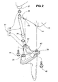
- the oil strainer 30 is constructed of a strainer case 31 disposed at the very bottom, a lower O-ring (first seal member) 32 disposed above the strainer case 31, an oil tube 33 disposed above the lower O-ring 32, and an upper O-ring (second seal member) 34 disposed above the oil tube 33, as shown in FIG. 2 .
- the oil strainer 30 is assembled by fitting the lower O-ring 32 and a lower end 36 of the oil tube 33 in an oil outlet 35 of the strainer case 31, fitting the upper O-ring 34 and an upper end 38 of the oil tube 33 in an inlet 37 of an oil channel (described in detail below), and attaching two bolts 45, 46 to two connector holes 41, 42 provided via a reinforcing part 39 to an upper part of the strainer case 31 and two connecting screw holes 43, 44 (described in detail below) provided to the mount case 13.
- the oil tube 33 has a shape symmetrical at the top and bottom. Because the shape is symmetrical at the top and bottom, the orientation has no effect when the oil tube 33 is inserted into the oil outlet 35 of the strainer case 31 and the inlet 37 to the oil channel. Therefore, the oil tube 33 is easier to assemble because the oil tube 33 can be inserted into the oil outlet 35 of the strainer case 31 and the inlet 37 to the oil channel without regard for the vertical direction.
- the following is a detailed description of the structure of the oil strainer 30.
- the oil strainer 30 includes the strainer case 31 constructed, for example, of a woven wire mesh, used to house an oil-filtering element 47, provided with an oil inlet 48 and the oil outlet 35, and connected to the mount case 13 (the connection structure is described below); the oil tube 33 extending from the oil outlet 35 to the inlet 37 of an oil channel 49 formed in the mount case 13; the lower O-ring 32 fitted into the lower end 36 of the oil tube 33, compressed at the oil outlet 35, and made to operate as a seal; and the upper O-ring 34 fitted into the upper end 38 of the oil tube 33, compressed at the inlet 37 of the oil channel 49, and made to operate as a seal.
- the strainer case 31 constructed, for example, of a woven wire mesh, used to house an oil-filtering element 47, provided with an oil inlet 48 and the oil outlet 35, and connected to the mount case 13 (the connection structure is described below); the oil tube 33 extending from the oil outlet 35 to the inlet 37 of an oil channel 49 formed in the mount case 13; the lower
- the element 47 in the embodiment is constructed of a woven metal mesh, but the element may be constructed of a perforated plate.
- An oil pump 51 is provided to the mount case 13 so as to be disposed on the right side of the oil channel 49.
- the oil pump 51 is constructed of an inner rotor 52 attached to the drive shaft 17 linked to the crankshaft of the engine 11, an outer rotor 53 in gear with the inner rotor 52, and a pump casing 54 for rotatably supporting the outer rotor 53.
- the oil strainer 30 is disposed in the suction area of the oil pump 51, the oil in the oil pan 14 is drawn through the oil inlet 48 of the oil strainer 30, the element 47, the oil tube 33, and the oil channel 49 along arrow (1) when the engine 11 is started and the oil pump 51 is operated. The indrawn oil is supplied to each part of the engine 11 from the oil pump 51.
- first seal member is the lower O-ring 32
- second seal member is the upper O-ring 34.
- O-rings are readily available and inexpensive. As a result, it is possible to reduce the manufacturing cost of the oil strainer 30.
- a first stepped part 55 for restricting axial movement of the lower O-ring 32 is provided to the lower end 36 of the oil tube 33
- a second stepped part 56 for restricting axial movement of the upper O-ring 34 is provided to the upper end 38 of the oil tube 33.
- the strainer case 31 is further constructed of a case lower half 57 formed of a resin material having the oil inlet 48, and a case upper half 58 formed of a resin material having the oil outlet 35. Because the two case halves 57, 58 are constructed of a resin material, the strainer case 31 can be made more lightweight compared with cases in which the two case halves are made of metal.
- Reinforcing ribs 59, 61 extending forward from the case upper half 58 are members that constitute one part of a reinforcing part 39 ( FIG. 2 ).
- case lower half 57 and the case upper half 58 are joined by a thermal welded part 62 (described in detail below).
- a thermal welded part 62 (described in detail below). The following is a description of the connection structure of the strainer case 31 and the mount case 13.
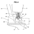
- the strainer case 31 is attached to the mount case 13 by passing the bolt 46 through the connector hole 42 and screwing the bolt into the connecting screw hole 44 in the mount case 13, as shown in FIG. 4 .
- the connector hole 42 is formed by attaching a cylindrical member 64 to a connector 63.
- the length L1 from a surface of the element (here, the thermal welded part 62) to the fastening part of the bolt 46 is made small. Therefore, even in cases in which the oil drawn up by the oil pump 51 ( FIG. 3 ) collides with the element 47 ( FIG. 3 ) and vibration occurs, the load applied to the fastening part of the bolt 46 can be reduced.
- the thermal welded part 62 is a region in which a welded member 72 extending upward from an end part 71 of the case lower half 57 is joined by heat to a welded surface 69 of a depressed part 68 formed so as to form a downward concavity in an end part 67 of the case upper half 58 in a state in which the element 47 is wedged between an upper surface 65 of the case lower half 57 and a lower surface 66 of the case upper half 58.
- a distal end of the welded member 72 protrudes before welding as shown by the imaginary line, and is flattened by heat after welding.
- the element 47 is wedged between the case lower half 57 and the case upper half 58 in the strainer case 31, and the case upper half 57 and the case lower half 58 are joined together by the thermal welded part 62. Because the case lower half 57 and the case upper half 58 are joined by the thermal welded part 62, the strainer case 31 can be made more lightweight compared with cases in which the two case halves 57, 58 are integrated by bolting.
- the lower O-ring 32 and the lower end 36 of the oil tube 33 are inserted into the oil outlet 35 of the strainer case 31 along arrow (2), as shown in FIG. 6(a) .
- the upper end 38 of the oil tube 33 and the upper O-ring 34 are then inserted into the inlet 37 of the oil channel 49 ( FIG. 3 ) along arrow (3), as shown in FIG. 6(b) .
- the lower end 36 of the oil tube 33 is supported by the lower O-ring 32 inserted into the oil outlet 35 of the strainer case 31, and the upper end 38 is supported by the upper O-ring 34 inserted into the inlet 37 of the oil channel. Therefore, the oil tube 33 can be easily removed from the strainer case 31. In cases in which the situation demands that the position of the strainer case 31 be changed, only the oil tube 33 of a different length should be prepared, and the strainer case 31 can be used with the new tube.
- the position of the strainer case 31 can therefore be changed at a lower cost compared with an oil strainer integrally constructed of a strainer case and an oil tube. Accordingly, there can be provided an oil strainer for use in an outboard motor unit wherein the position of the strainer case 31 can be changed at a low cost.
- the lower O-ring 32 is used to seal the lower end 36 of the oil tube 33
- the upper O-ring 34 is used to seal the upper end 38 of the oil tube 33.
- a tapered part 73 is further provided to an upper end of the strainer case 31, as shown in FIG. 6(c) .
- the presence of the tapered part 73 allows the lower O-ring 32 to be smoothly fitted into the oil outlet 35.
- a tapered part 74 is provided to a lower end of the mount case 13. The presence of the tapered part 74 allows the upper O-ring 34 to be smoothly fitted into the inlet 37 of the oil channel.
- O-rings are used for the first seal member and the second seal member according to the present invention, but soft resin members, rubber members, or members constructed by combining resin and rubber can also be used, making it possible to use a general seal material.
- the oil strainer of the present invention can be used in an outboard motor unit.
Landscapes
- Engineering & Computer Science (AREA)
- Mechanical Engineering (AREA)
- General Engineering & Computer Science (AREA)
- Lubrication Details And Ventilation Of Internal Combustion Engines (AREA)
Abstract
Description
- This invention relates to an oil strainer housed in an outboard motor unit.
- Outboard motor units have been known in the past as apparatuses for providing propulsion force to boats and other waterborne vehicles, as disclosed, for example, in Japanese Patent Application Laid-Open Publication No.
HEI-05-33779 JP H05-33779 A -
FIG. 7 hereof shows the outboard motor unit disclosed inJP H05-33779 A - An
engine 102 covered by anengine cover 101 is provided to an upper part of theoutboard motor unit 100, as shown inFIG. 7(a) . Theoutboard motor unit 100 has astern bracket 105 and is attached to aback end 104 of awaterborne vehicle 103 via thestern bracket 105. Theengine 102 is supported by amount case 106. Anoil pan 107 is attached to an underside of themount case 106. The internal structure of theoil pan 107 is described on the basis ofFIG. 7(b) . - With reference to
FIG. 7(b) , theoil strainer 109 is connected to thesuction port 108 of an oil pump. Theoil strainer 109 is attached to themount case 106 via a supportingmember 111. - The
oil strainer 109 disclosed in Japanese Laid-open Patent Application No.5-33779 strainer case 112 in which an element is housed, and anoil tube 113 for connecting thestrainer case 112 and thesuction port 108 of the oil pump. Therefore, the position of thestrainer case 112 is fixed. It is necessary to newly prepare an oil strainer having an oil tube of a different length when the position of thestrainer case 112 is changed as needed. The result is an increase in the replacement cost of oil strainers. - It is therefore an object of the present invention to provide an oil strainer for an engine used in an outboard motor unit wherein the position of the oil strainer can be varied at a low cost.
- According to an aspect of the present invention, there is provided an oil strainer adapted to be disposed in a suction area of an oil pump of an outboard engine unit, for filtering oil and supplying the filtered oil to the oil pump via an oil channel, which oil strainer comprises: a strainer case with a filtering element housed therein, the strainer case being provided with an oil inlet and an oil outlet; an oil tube extending from the oil outlet to an inlet of the oil channel; a first seal member fitted into one end of the oil tube and compressed at the oil outlet to operate as a seal; and a second seal member fitted into an opposite end of the oil tube and compressed at the inlet to the oil channel to operate as a seal, wherein the oil tube is supported at both ends by the first seal member and the second seal member.
- With this arrangement, the oil tube can be easily removed from the strainer case. In cases in which the situation demands that the position of the strainer case be changed, only the oil tube of a different length should be prepared, and the strainer case can be used with the new tube. Hence, the position of the strainer case can be changed at a lower cost compared with an oil strainer integrally constructed of a strainer case and an oil tube. Accordingly, there can be provided an oil strainer for use in an outboard motor unit wherein the position of the strainer case can be changed at a low cost.
- Preferably, each of the first seal member and the second seal member comprises an O-ring. O-rings are readily available and inexpensive. Hence, it is possible to reduce the manufacturing cost of the oil strainer.
- Desirably, the one end of the oil tube has a first stepped part for restricting axial movement of the first seal member while the opposite end of the oil tube has a second stepped part for restricting axial movement of the second seal member. As a result, the first seal member will not go beyond the first stepped part, and the second seal member will not go beyond the second stepped part. For this reason, the first seal member and the second seal member remain in a predetermined area, allowing the sealing properties of the oil outlet of the strainer case and the inlet of the oil channel to be further improved.
- In a preferred form, the strainer case include a case lower half formed of a resin material having the oil inlet, and a case upper half formed of a resin material having the oil outlet. Therefore, the strainer case can be made more lightweight compared with cases in which the two case halves are made of metal.
- It is desirable that the element be wedged between the case lower half and the case upper half, and be joined to the case lower half and the case upper half by a thermal welded part. Accordingly, the strainer case can be made more lightweight compared with cases in which the two case halves are integrated by bolting.
- A preferred embodiment of the present invention will be described in detail below, by way of example only, with reference to the accompanying drawings, in which:
-
FIG. 1 is a side elevational view showing an outboard engine unit having an oil strainer according to the present invention; -
FIG. 2 is an exploded perspective view of the oil strainer according to the present invention; -
FIG. 3 is a cross-sectional view illustrating the oil strainer ofFIG. 2 ; -
FIG. 4 is a partial cross-sectional view illustrating a strainer case and a mount case at a connection; -
FIG. 5 is an enlarged view ofregion 5 ofFIG. 3 ; -
FIG. 6 is a view illustrating a mode of attachment of an oil tube; and -
FIG. 7 is a view showing a conventional outboard motor unit and oil strainer. - An
outboard motor unit 10 shown inFIG. 1 includes anengine cover 12 that covers anengine 11, the cover being provided to an upper part; an undercover 15 connected to a lower end of theengine cover 12 and made to extend downward while covering a lower part of theengine 11, amount case 13, and an upper half of anoil pan 14; anextension cover 16 connected to a lower end of the undercover 15 and used to cover a lower half of theoil pan 14; and agear case 21 connected to a lower end of theextension cover 16 and used to house agear mechanism 18 and adrive shaft 17 linked to a crankshaft of theengine 11. Apropeller 19 is rotated via thegear mechanism 18 and thedrive shaft 17 by the running of theengine 11. - The
outboard motor unit 10 is provided with astern bracket 24 attached to aback end 23 of a boat or otherwaterborne vehicle 22, aswivel case 25 rotatably attached to thestern bracket 24, a backwardly extendingmount frame 27 supporting themount case 13 and having aswivel shaft 26 rotatably inserted into theswivel case 25, and a backwardly extending lowermount center housing 28 linked to the lower end of theswivel shaft 26 and to theextension cover 16. - In addition, an oil strainer 30 (described in detail below) is provided to the interior of the
oil pan 14. - The
oil strainer 30 is constructed of astrainer case 31 disposed at the very bottom, a lower O-ring (first seal member) 32 disposed above thestrainer case 31, anoil tube 33 disposed above the lower O-ring 32, and an upper O-ring (second seal member) 34 disposed above theoil tube 33, as shown inFIG. 2 . - The
oil strainer 30 is assembled by fitting the lower O-ring 32 and alower end 36 of theoil tube 33 in anoil outlet 35 of thestrainer case 31, fitting the upper O-ring 34 and anupper end 38 of theoil tube 33 in aninlet 37 of an oil channel (described in detail below), and attaching twobolts connector holes part 39 to an upper part of thestrainer case 31 and two connectingscrew holes 43, 44 (described in detail below) provided to themount case 13. - The
oil tube 33 has a shape symmetrical at the top and bottom. Because the shape is symmetrical at the top and bottom, the orientation has no effect when theoil tube 33 is inserted into theoil outlet 35 of thestrainer case 31 and theinlet 37 to the oil channel. Therefore, theoil tube 33 is easier to assemble because theoil tube 33 can be inserted into theoil outlet 35 of thestrainer case 31 and theinlet 37 to the oil channel without regard for the vertical direction. The following is a detailed description of the structure of theoil strainer 30. - As shown in
FIG. 3 , theoil strainer 30 includes thestrainer case 31 constructed, for example, of a woven wire mesh, used to house an oil-filteringelement 47, provided with anoil inlet 48 and theoil outlet 35, and connected to the mount case 13 (the connection structure is described below); theoil tube 33 extending from theoil outlet 35 to theinlet 37 of anoil channel 49 formed in themount case 13; the lower O-ring 32 fitted into thelower end 36 of theoil tube 33, compressed at theoil outlet 35, and made to operate as a seal; and the upper O-ring 34 fitted into theupper end 38 of theoil tube 33, compressed at theinlet 37 of theoil channel 49, and made to operate as a seal. - The
element 47 in the embodiment is constructed of a woven metal mesh, but the element may be constructed of a perforated plate. - An
oil pump 51 is provided to themount case 13 so as to be disposed on the right side of theoil channel 49. Theoil pump 51 is constructed of aninner rotor 52 attached to thedrive shaft 17 linked to the crankshaft of theengine 11, anouter rotor 53 in gear with theinner rotor 52, and apump casing 54 for rotatably supporting theouter rotor 53. - Because the
oil strainer 30 is disposed in the suction area of theoil pump 51, the oil in theoil pan 14 is drawn through theoil inlet 48 of theoil strainer 30, theelement 47, theoil tube 33, and theoil channel 49 along arrow (1) when theengine 11 is started and theoil pump 51 is operated. The indrawn oil is supplied to each part of theengine 11 from theoil pump 51. - In addition, the first seal member is the lower O-ring 32, and the second seal member is the upper O-ring 34. O-rings are readily available and inexpensive. As a result, it is possible to reduce the manufacturing cost of the
oil strainer 30. - Additionally, a first stepped
part 55 for restricting axial movement of the lower O-ring 32 is provided to thelower end 36 of theoil tube 33, and a second steppedpart 56 for restricting axial movement of the upper O-ring 34 is provided to theupper end 38 of theoil tube 33. The lower O-ring 32 will not go beyond the first steppedpart 55, and the upper O-ring 34 will not go beyond the second steppedpart 56. For this reason, the lower O-ring 32 and the upper O-ring 34 remain in a predetermined area, allowing the sealing properties of theoil outlet 35 of thestrainer case 31 and theinlet 37 of theoil channel 49 to be further improved. - The
strainer case 31 is further constructed of a caselower half 57 formed of a resin material having theoil inlet 48, and a caseupper half 58 formed of a resin material having theoil outlet 35. Because the twocase halves strainer case 31 can be made more lightweight compared with cases in which the two case halves are made of metal. - Reinforcing
ribs upper half 58 are members that constitute one part of a reinforcing part 39 (FIG. 2 ). - In addition, the case
lower half 57 and the caseupper half 58 are joined by a thermal welded part 62 (described in detail below). The following is a description of the connection structure of thestrainer case 31 and themount case 13. - The
strainer case 31 is attached to themount case 13 by passing thebolt 46 through theconnector hole 42 and screwing the bolt into the connectingscrew hole 44 in themount case 13, as shown inFIG. 4 . Theconnector hole 42 is formed by attaching acylindrical member 64 to aconnector 63. - In the
strainer case 31, the length L1 from a surface of the element (here, the thermal welded part 62) to the fastening part of thebolt 46 is made small. Therefore, even in cases in which the oil drawn up by the oil pump 51 (FIG. 3 ) collides with the element 47 (FIG. 3 ) and vibration occurs, the load applied to the fastening part of thebolt 46 can be reduced. The following describes the structure of the thermal weldedpart 62 of the caselower half 57 and the caseupper half 58. - As shown in
FIG. 5 , the thermal weldedpart 62 is a region in which a weldedmember 72 extending upward from anend part 71 of the caselower half 57 is joined by heat to a weldedsurface 69 of adepressed part 68 formed so as to form a downward concavity in anend part 67 of the caseupper half 58 in a state in which theelement 47 is wedged between anupper surface 65 of the caselower half 57 and alower surface 66 of the caseupper half 58. A distal end of the weldedmember 72 protrudes before welding as shown by the imaginary line, and is flattened by heat after welding. - That is, the
element 47 is wedged between the caselower half 57 and the caseupper half 58 in thestrainer case 31, and the caseupper half 57 and the caselower half 58 are joined together by the thermal weldedpart 62. Because the caselower half 57 and the caseupper half 58 are joined by the thermal weldedpart 62, thestrainer case 31 can be made more lightweight compared with cases in which the two case halves 57, 58 are integrated by bolting. - Described next is the operation of the oil strainer described above. Specifically, a description is given of the attachment sequence all the way to the attachment of the oil tube to the inlet of the oil channel, which continues to the oil outlet of the strainer case and the oil pump.
- The lower O-
ring 32 and thelower end 36 of theoil tube 33 are inserted into theoil outlet 35 of thestrainer case 31 along arrow (2), as shown inFIG. 6(a) . - The
upper end 38 of theoil tube 33 and the upper O-ring 34 are then inserted into theinlet 37 of the oil channel 49 (FIG. 3 ) along arrow (3), as shown inFIG. 6(b) . - The result is that the
lower end 36 of theoil tube 33 is supported by the lower O-ring 32 fitted into theoil outlet 35 of thestrainer case 31, and theupper end 38 is supported by the upper O-ring 34 fitted into theinlet 37 of the oil channel, as shown inFIG. 6(c) . - The
lower end 36 of theoil tube 33 is supported by the lower O-ring 32 inserted into theoil outlet 35 of thestrainer case 31, and theupper end 38 is supported by the upper O-ring 34 inserted into theinlet 37 of the oil channel. Therefore, theoil tube 33 can be easily removed from thestrainer case 31. In cases in which the situation demands that the position of thestrainer case 31 be changed, only theoil tube 33 of a different length should be prepared, and thestrainer case 31 can be used with the new tube. - In the oil strainer 30 (
FIG. 2 ) according to the present invention, the position of thestrainer case 31 can therefore be changed at a lower cost compared with an oil strainer integrally constructed of a strainer case and an oil tube. Accordingly, there can be provided an oil strainer for use in an outboard motor unit wherein the position of thestrainer case 31 can be changed at a low cost. - In addition, the lower O-
ring 32 is used to seal thelower end 36 of theoil tube 33, and the upper O-ring 34 is used to seal theupper end 38 of theoil tube 33. The oil-sealing properties can be maintained, and the vibrations transmitted from theoil tube 33 to thestrainer case 31 can be reduced by using the lower O-ring 32 and the upper O-ring 34. - A
tapered part 73 is further provided to an upper end of thestrainer case 31, as shown inFIG. 6(c) . The presence of thetapered part 73 allows the lower O-ring 32 to be smoothly fitted into theoil outlet 35. Atapered part 74 is provided to a lower end of themount case 13. The presence of thetapered part 74 allows the upper O-ring 34 to be smoothly fitted into theinlet 37 of the oil channel. - In this embodiment, O-rings are used for the first seal member and the second seal member according to the present invention, but soft resin members, rubber members, or members constructed by combining resin and rubber can also be used, making it possible to use a general seal material.
- The oil strainer of the present invention can be used in an outboard motor unit.
Claims (5)
- An oil strainer (30) adapted to be disposed in a suction area of an oil pump (51) of an outboard engine unit, for filtering oil and supplying the filtered oil to the oil pump (51) via an oil channel (49), the oil strainer comprising:a strainer case (31) with a filtering element (47) housed therein, the strainer case being provided with an oil inlet (48) and an oil outlet (35);an oil tube (33) extending from the oil outlet (35) to an inlet (37) of the oil channel (49);a first seal member (32) fitted into one end (36) of the oil tube (33) and compressed at the oil outlet (35) to operate as a seal; anda second seal member (34) fitted into an opposite end (38) of the oil tube (33) and compressed at the inlet (37) to the oil channel (49) to operate as a seal,wherein the oil tube (33) is supported at both ends by the first seal member (32) and the second seal member (34).
- The oil strainer of claim 1, wherein each of the first seal member (32) and the second seal member (34) comprises an O-ring.
- The oil strainer of claim 1 or 2, wherein the one end (36) of the oil tube (33) has a first stepped part (55) for restricting axial movement of the first seal member (32), and the opposite end (38) of the oil tube (33) has a second stepped part (56) for restricting axial movement of the second seal member (34).
- The oil strainer of claim 1, 2 or 3, wherein the strainer case (31) comprises a case lower half (57) formed of a resin material having the oil inlet (48), and a case upper half (58) formed of a resin material having the oil outlet (35).
- The oil strainer of claim 4, wherein the element (47) is wedged between the case lower half (57) and the case upper half (58), and is joined to the case lower half (57) and the case upper half (58) by a thermal welded part (62).
Applications Claiming Priority (1)
| Application Number | Priority Date | Filing Date | Title |
|---|---|---|---|
| JP2009128106A JP5279615B2 (en) | 2009-05-27 | 2009-05-27 | Oil strainer for outboard engine |
Publications (2)
| Publication Number | Publication Date |
|---|---|
| EP2264289A1 true EP2264289A1 (en) | 2010-12-22 |
| EP2264289B1 EP2264289B1 (en) | 2014-04-02 |
Family
ID=42668717
Family Applications (1)
| Application Number | Title | Priority Date | Filing Date |
|---|---|---|---|
| EP10250940.3A Active EP2264289B1 (en) | 2009-05-27 | 2010-05-17 | Oil strainer for outboard motor unit |
Country Status (4)
| Country | Link |
|---|---|
| US (1) | US8408401B2 (en) |
| EP (1) | EP2264289B1 (en) |
| JP (1) | JP5279615B2 (en) |
| CA (1) | CA2703420C (en) |
Cited By (1)
| Publication number | Priority date | Publication date | Assignee | Title |
|---|---|---|---|---|
| EP2754863A3 (en) * | 2013-01-15 | 2015-09-16 | MAN Truck & Bus AG | Device for the sealed connection of communicating channels in adjacent and/or connected parts of a combustion engine |
Families Citing this family (3)
| Publication number | Priority date | Publication date | Assignee | Title |
|---|---|---|---|---|
| CN106050357B (en) * | 2016-08-15 | 2018-08-07 | 潍柴动力股份有限公司 | A kind of internal combustion engine, lubricating system and sump strainer |
| US11028741B1 (en) * | 2020-08-24 | 2021-06-08 | Apq Development, Llc | Oil pick-up assembly |
| JP7586050B2 (en) | 2021-10-28 | 2024-11-19 | トヨタ自動車株式会社 | Oil strainer |
Citations (6)
| Publication number | Priority date | Publication date | Assignee | Title |
|---|---|---|---|---|
| JPS6365112A (en) * | 1986-09-04 | 1988-03-23 | Yamaha Motor Co Ltd | Engine lubrication device |
| DE3913813A1 (en) * | 1988-04-26 | 1989-11-09 | Honda Motor Co Ltd | OIL TANK ARRANGEMENT FOR MOTORS |
| JPH0533779A (en) | 1991-07-26 | 1993-02-09 | Suzuki Motor Corp | Outboard oil pump |
| EP1055803A1 (en) * | 1999-05-24 | 2000-11-29 | Yamaha Hatsudoki Kabushiki Kaisha | Engine device |
| EP1903191A2 (en) * | 2006-08-28 | 2008-03-26 | HONDA MOTOR CO., Ltd. | Oil strainer structure of engine and oil return structure of engine |
| US20080237111A1 (en) * | 2007-03-29 | 2008-10-02 | Toyota Engineering & Manufacturing North America, Inc. | Removable Shield In An Engine Oil Strainer |
Family Cites Families (14)
| Publication number | Priority date | Publication date | Assignee | Title |
|---|---|---|---|---|
| US4066281A (en) | 1976-07-16 | 1978-01-03 | Bonis John C De | Porsche automobile oil drain replacement tube |
| JPS6117111A (en) | 1984-07-02 | 1986-01-25 | Minolta Camera Co Ltd | Auto-focusing device with backlash compensation and interchangeable lens |
| JPS6117111U (en) * | 1984-07-04 | 1986-01-31 | 本田技研工業株式会社 | Oil strainer oil pipe connection device |
| JPH0248675Y2 (en) * | 1985-07-15 | 1990-12-20 | ||
| JPS6216734A (en) | 1985-07-17 | 1987-01-24 | 松下電器産業株式会社 | dishwasher |
| JPS6390012A (en) | 1986-10-01 | 1988-04-20 | Sharp Corp | Magnetic head |
| JPH0218258Y2 (en) * | 1986-12-02 | 1990-05-22 | ||
| JP2580247B2 (en) * | 1988-04-26 | 1997-02-12 | 本田技研工業株式会社 | Engine oil reservoir structure |
| JP3769070B2 (en) * | 1996-05-27 | 2006-04-19 | 本田技研工業株式会社 | Lubricating oil return passage device in an engine |
| JP2003334406A (en) * | 2002-05-21 | 2003-11-25 | Nok Corp | Oil strainer |
| JP2003262133A (en) * | 2003-02-10 | 2003-09-19 | Honda Motor Co Ltd | Outboard motor |
| US7087160B2 (en) * | 2003-05-29 | 2006-08-08 | Spx Corporation | Outside-in flow engine and transmission filter and method |
| JPWO2007010721A1 (en) * | 2005-07-21 | 2009-01-29 | Nok株式会社 | Oil strainer |
| JP2008232017A (en) * | 2007-03-20 | 2008-10-02 | Daikyo Nishikawa Kk | Oil strainer for engine |
-
2009
- 2009-05-27 JP JP2009128106A patent/JP5279615B2/en active Active
-
2010
- 2010-05-12 CA CA2703420A patent/CA2703420C/en not_active Expired - Fee Related
- 2010-05-17 EP EP10250940.3A patent/EP2264289B1/en active Active
- 2010-05-17 US US12/781,576 patent/US8408401B2/en active Active
Patent Citations (6)
| Publication number | Priority date | Publication date | Assignee | Title |
|---|---|---|---|---|
| JPS6365112A (en) * | 1986-09-04 | 1988-03-23 | Yamaha Motor Co Ltd | Engine lubrication device |
| DE3913813A1 (en) * | 1988-04-26 | 1989-11-09 | Honda Motor Co Ltd | OIL TANK ARRANGEMENT FOR MOTORS |
| JPH0533779A (en) | 1991-07-26 | 1993-02-09 | Suzuki Motor Corp | Outboard oil pump |
| EP1055803A1 (en) * | 1999-05-24 | 2000-11-29 | Yamaha Hatsudoki Kabushiki Kaisha | Engine device |
| EP1903191A2 (en) * | 2006-08-28 | 2008-03-26 | HONDA MOTOR CO., Ltd. | Oil strainer structure of engine and oil return structure of engine |
| US20080237111A1 (en) * | 2007-03-29 | 2008-10-02 | Toyota Engineering & Manufacturing North America, Inc. | Removable Shield In An Engine Oil Strainer |
Cited By (1)
| Publication number | Priority date | Publication date | Assignee | Title |
|---|---|---|---|---|
| EP2754863A3 (en) * | 2013-01-15 | 2015-09-16 | MAN Truck & Bus AG | Device for the sealed connection of communicating channels in adjacent and/or connected parts of a combustion engine |
Also Published As
| Publication number | Publication date |
|---|---|
| CA2703420A1 (en) | 2010-11-27 |
| US20100300958A1 (en) | 2010-12-02 |
| CA2703420C (en) | 2013-11-19 |
| JP5279615B2 (en) | 2013-09-04 |
| EP2264289B1 (en) | 2014-04-02 |
| US8408401B2 (en) | 2013-04-02 |
| JP2010275903A (en) | 2010-12-09 |
Similar Documents
| Publication | Publication Date | Title |
|---|---|---|
| KR101628674B1 (en) | Motor-pump assembly | |
| EP2264289B1 (en) | Oil strainer for outboard motor unit | |
| EP2233186B1 (en) | Vehicle fuel supply device and fuel filter structure | |
| WO2002016753A1 (en) | Fuel feeder | |
| JP2007055310A (en) | Outboard motor | |
| EP3372488A1 (en) | Outboard motor | |
| JPH02256809A (en) | Lubrication device for four-cycle outboard motor | |
| US6427655B2 (en) | Intake manifold of outboard motor | |
| JP2020101097A (en) | Outboard engine | |
| JP4572166B2 (en) | Oil strainer | |
| US6189501B1 (en) | Lubricating apparatus for engine | |
| JP4273324B2 (en) | Fuel filter | |
| JP4416642B2 (en) | Outboard motor | |
| US7217166B2 (en) | Cowling structure for outboard motor | |
| JP2005127161A (en) | Engine unit case | |
| JP2001050129A (en) | Fuel supply device in fuel injection device | |
| JP2001342815A (en) | Engine lubrication device | |
| JP4751247B2 (en) | Mounting structure of equipment to fuel tank | |
| JP2010007627A (en) | Strainer | |
| JP4602244B2 (en) | Motorcycle fuel supply system | |
| JP3917879B2 (en) | Engine mist separator | |
| JP4979350B2 (en) | Fuel pump unit, fuel pump module, fuel supply device, and fuel tank unit including any of these | |
| JP4387158B2 (en) | Drive shaft support structure for jet propulsion boat | |
| JP3864619B2 (en) | Outboard motor | |
| JP2009127607A (en) | Fuel supply device |
Legal Events
| Date | Code | Title | Description |
|---|---|---|---|
| PUAI | Public reference made under article 153(3) epc to a published international application that has entered the european phase |
Free format text: ORIGINAL CODE: 0009012 |
|
| 17P | Request for examination filed |
Effective date: 20100604 |
|
| AK | Designated contracting states |
Kind code of ref document: A1 Designated state(s): AL AT BE BG CH CY CZ DE DK EE ES FI FR GB GR HR HU IE IS IT LI LT LU LV MC MK MT NL NO PL PT RO SE SI SK SM TR |
|
| AX | Request for extension of the european patent |
Extension state: BA ME RS |
|
| 17Q | First examination report despatched |
Effective date: 20120312 |
|
| GRAP | Despatch of communication of intention to grant a patent |
Free format text: ORIGINAL CODE: EPIDOSNIGR1 |
|
| INTG | Intention to grant announced |
Effective date: 20130604 |
|
| GRAP | Despatch of communication of intention to grant a patent |
Free format text: ORIGINAL CODE: EPIDOSNIGR1 |
|
| INTG | Intention to grant announced |
Effective date: 20140121 |
|
| GRAS | Grant fee paid |
Free format text: ORIGINAL CODE: EPIDOSNIGR3 |
|
| GRAA | (expected) grant |
Free format text: ORIGINAL CODE: 0009210 |
|
| AK | Designated contracting states |
Kind code of ref document: B1 Designated state(s): AL AT BE BG CH CY CZ DE DK EE ES FI FR GB GR HR HU IE IS IT LI LT LU LV MC MK MT NL NO PL PT RO SE SI SK SM TR |
|
| REG | Reference to a national code |
Ref country code: GB Ref legal event code: FG4D |
|
| REG | Reference to a national code |
Ref country code: AT Ref legal event code: REF Ref document number: 660286 Country of ref document: AT Kind code of ref document: T Effective date: 20140415 Ref country code: CH Ref legal event code: EP |
|
| REG | Reference to a national code |
Ref country code: IE Ref legal event code: FG4D |
|
| REG | Reference to a national code |
Ref country code: DE Ref legal event code: R096 Ref document number: 602010014764 Country of ref document: DE Effective date: 20140515 |
|
| REG | Reference to a national code |
Ref country code: AT Ref legal event code: MK05 Ref document number: 660286 Country of ref document: AT Kind code of ref document: T Effective date: 20140402 |
|
| REG | Reference to a national code |
Ref country code: NL Ref legal event code: VDEP Effective date: 20140402 |
|
| REG | Reference to a national code |
Ref country code: LT Ref legal event code: MG4D |
|
| PG25 | Lapsed in a contracting state [announced via postgrant information from national office to epo] |
Ref country code: GR Free format text: LAPSE BECAUSE OF FAILURE TO SUBMIT A TRANSLATION OF THE DESCRIPTION OR TO PAY THE FEE WITHIN THE PRESCRIBED TIME-LIMIT Effective date: 20140703 Ref country code: BG Free format text: LAPSE BECAUSE OF FAILURE TO SUBMIT A TRANSLATION OF THE DESCRIPTION OR TO PAY THE FEE WITHIN THE PRESCRIBED TIME-LIMIT Effective date: 20140702 Ref country code: IS Free format text: LAPSE BECAUSE OF FAILURE TO SUBMIT A TRANSLATION OF THE DESCRIPTION OR TO PAY THE FEE WITHIN THE PRESCRIBED TIME-LIMIT Effective date: 20140802 Ref country code: FI Free format text: LAPSE BECAUSE OF FAILURE TO SUBMIT A TRANSLATION OF THE DESCRIPTION OR TO PAY THE FEE WITHIN THE PRESCRIBED TIME-LIMIT Effective date: 20140402 Ref country code: CY Free format text: LAPSE BECAUSE OF FAILURE TO SUBMIT A TRANSLATION OF THE DESCRIPTION OR TO PAY THE FEE WITHIN THE PRESCRIBED TIME-LIMIT Effective date: 20140402 Ref country code: NO Free format text: LAPSE BECAUSE OF FAILURE TO SUBMIT A TRANSLATION OF THE DESCRIPTION OR TO PAY THE FEE WITHIN THE PRESCRIBED TIME-LIMIT Effective date: 20140702 Ref country code: LT Free format text: LAPSE BECAUSE OF FAILURE TO SUBMIT A TRANSLATION OF THE DESCRIPTION OR TO PAY THE FEE WITHIN THE PRESCRIBED TIME-LIMIT Effective date: 20140402 Ref country code: NL Free format text: LAPSE BECAUSE OF FAILURE TO SUBMIT A TRANSLATION OF THE DESCRIPTION OR TO PAY THE FEE WITHIN THE PRESCRIBED TIME-LIMIT Effective date: 20140402 Ref country code: CZ Free format text: LAPSE BECAUSE OF FAILURE TO SUBMIT A TRANSLATION OF THE DESCRIPTION OR TO PAY THE FEE WITHIN THE PRESCRIBED TIME-LIMIT Effective date: 20140402 |
|
| PG25 | Lapsed in a contracting state [announced via postgrant information from national office to epo] |
Ref country code: AT Free format text: LAPSE BECAUSE OF FAILURE TO SUBMIT A TRANSLATION OF THE DESCRIPTION OR TO PAY THE FEE WITHIN THE PRESCRIBED TIME-LIMIT Effective date: 20140402 Ref country code: LV Free format text: LAPSE BECAUSE OF FAILURE TO SUBMIT A TRANSLATION OF THE DESCRIPTION OR TO PAY THE FEE WITHIN THE PRESCRIBED TIME-LIMIT Effective date: 20140402 Ref country code: PL Free format text: LAPSE BECAUSE OF FAILURE TO SUBMIT A TRANSLATION OF THE DESCRIPTION OR TO PAY THE FEE WITHIN THE PRESCRIBED TIME-LIMIT Effective date: 20140402 Ref country code: SE Free format text: LAPSE BECAUSE OF FAILURE TO SUBMIT A TRANSLATION OF THE DESCRIPTION OR TO PAY THE FEE WITHIN THE PRESCRIBED TIME-LIMIT Effective date: 20140402 Ref country code: HR Free format text: LAPSE BECAUSE OF FAILURE TO SUBMIT A TRANSLATION OF THE DESCRIPTION OR TO PAY THE FEE WITHIN THE PRESCRIBED TIME-LIMIT Effective date: 20140402 Ref country code: ES Free format text: LAPSE BECAUSE OF FAILURE TO SUBMIT A TRANSLATION OF THE DESCRIPTION OR TO PAY THE FEE WITHIN THE PRESCRIBED TIME-LIMIT Effective date: 20140402 |
|
| PG25 | Lapsed in a contracting state [announced via postgrant information from national office to epo] |
Ref country code: PT Free format text: LAPSE BECAUSE OF FAILURE TO SUBMIT A TRANSLATION OF THE DESCRIPTION OR TO PAY THE FEE WITHIN THE PRESCRIBED TIME-LIMIT Effective date: 20140804 |
|
| REG | Reference to a national code |
Ref country code: CH Ref legal event code: PL |
|
| REG | Reference to a national code |
Ref country code: DE Ref legal event code: R097 Ref document number: 602010014764 Country of ref document: DE |
|
| PG25 | Lapsed in a contracting state [announced via postgrant information from national office to epo] |
Ref country code: BE Free format text: LAPSE BECAUSE OF FAILURE TO SUBMIT A TRANSLATION OF THE DESCRIPTION OR TO PAY THE FEE WITHIN THE PRESCRIBED TIME-LIMIT Effective date: 20140402 Ref country code: CH Free format text: LAPSE BECAUSE OF NON-PAYMENT OF DUE FEES Effective date: 20140531 Ref country code: EE Free format text: LAPSE BECAUSE OF FAILURE TO SUBMIT A TRANSLATION OF THE DESCRIPTION OR TO PAY THE FEE WITHIN THE PRESCRIBED TIME-LIMIT Effective date: 20140402 Ref country code: SK Free format text: LAPSE BECAUSE OF FAILURE TO SUBMIT A TRANSLATION OF THE DESCRIPTION OR TO PAY THE FEE WITHIN THE PRESCRIBED TIME-LIMIT Effective date: 20140402 Ref country code: RO Free format text: LAPSE BECAUSE OF FAILURE TO SUBMIT A TRANSLATION OF THE DESCRIPTION OR TO PAY THE FEE WITHIN THE PRESCRIBED TIME-LIMIT Effective date: 20140402 Ref country code: DK Free format text: LAPSE BECAUSE OF FAILURE TO SUBMIT A TRANSLATION OF THE DESCRIPTION OR TO PAY THE FEE WITHIN THE PRESCRIBED TIME-LIMIT Effective date: 20140402 Ref country code: MC Free format text: LAPSE BECAUSE OF FAILURE TO SUBMIT A TRANSLATION OF THE DESCRIPTION OR TO PAY THE FEE WITHIN THE PRESCRIBED TIME-LIMIT Effective date: 20140402 Ref country code: LI Free format text: LAPSE BECAUSE OF NON-PAYMENT OF DUE FEES Effective date: 20140531 |
|
| PLBE | No opposition filed within time limit |
Free format text: ORIGINAL CODE: 0009261 |
|
| STAA | Information on the status of an ep patent application or granted ep patent |
Free format text: STATUS: NO OPPOSITION FILED WITHIN TIME LIMIT |
|
| REG | Reference to a national code |
Ref country code: IE Ref legal event code: MM4A |
|
| 26N | No opposition filed |
Effective date: 20150106 |
|
| REG | Reference to a national code |
Ref country code: DE Ref legal event code: R097 Ref document number: 602010014764 Country of ref document: DE Effective date: 20150106 |
|
| PG25 | Lapsed in a contracting state [announced via postgrant information from national office to epo] |
Ref country code: IE Free format text: LAPSE BECAUSE OF NON-PAYMENT OF DUE FEES Effective date: 20140517 |
|
| PG25 | Lapsed in a contracting state [announced via postgrant information from national office to epo] |
Ref country code: SI Free format text: LAPSE BECAUSE OF FAILURE TO SUBMIT A TRANSLATION OF THE DESCRIPTION OR TO PAY THE FEE WITHIN THE PRESCRIBED TIME-LIMIT Effective date: 20140402 |
|
| PG25 | Lapsed in a contracting state [announced via postgrant information from national office to epo] |
Ref country code: MT Free format text: LAPSE BECAUSE OF FAILURE TO SUBMIT A TRANSLATION OF THE DESCRIPTION OR TO PAY THE FEE WITHIN THE PRESCRIBED TIME-LIMIT Effective date: 20140402 |
|
| REG | Reference to a national code |
Ref country code: FR Ref legal event code: PLFP Year of fee payment: 7 |
|
| PG25 | Lapsed in a contracting state [announced via postgrant information from national office to epo] |
Ref country code: SM Free format text: LAPSE BECAUSE OF FAILURE TO SUBMIT A TRANSLATION OF THE DESCRIPTION OR TO PAY THE FEE WITHIN THE PRESCRIBED TIME-LIMIT Effective date: 20140402 |
|
| PG25 | Lapsed in a contracting state [announced via postgrant information from national office to epo] |
Ref country code: LU Free format text: LAPSE BECAUSE OF NON-PAYMENT OF DUE FEES Effective date: 20140517 Ref country code: HU Free format text: LAPSE BECAUSE OF FAILURE TO SUBMIT A TRANSLATION OF THE DESCRIPTION OR TO PAY THE FEE WITHIN THE PRESCRIBED TIME-LIMIT; INVALID AB INITIO Effective date: 20100517 Ref country code: TR Free format text: LAPSE BECAUSE OF FAILURE TO SUBMIT A TRANSLATION OF THE DESCRIPTION OR TO PAY THE FEE WITHIN THE PRESCRIBED TIME-LIMIT Effective date: 20140402 |
|
| REG | Reference to a national code |
Ref country code: FR Ref legal event code: PLFP Year of fee payment: 8 |
|
| REG | Reference to a national code |
Ref country code: FR Ref legal event code: PLFP Year of fee payment: 9 |
|
| PG25 | Lapsed in a contracting state [announced via postgrant information from national office to epo] |
Ref country code: MK Free format text: LAPSE BECAUSE OF FAILURE TO SUBMIT A TRANSLATION OF THE DESCRIPTION OR TO PAY THE FEE WITHIN THE PRESCRIBED TIME-LIMIT Effective date: 20140402 |
|
| PG25 | Lapsed in a contracting state [announced via postgrant information from national office to epo] |
Ref country code: AL Free format text: LAPSE BECAUSE OF FAILURE TO SUBMIT A TRANSLATION OF THE DESCRIPTION OR TO PAY THE FEE WITHIN THE PRESCRIBED TIME-LIMIT Effective date: 20140402 |
|
| REG | Reference to a national code |
Ref country code: DE Ref legal event code: R084 Ref document number: 602010014764 Country of ref document: DE |
|
| REG | Reference to a national code |
Ref country code: GB Ref legal event code: 746 Effective date: 20191219 |
|
| REG | Reference to a national code |
Ref country code: DE Ref legal event code: R082 Ref document number: 602010014764 Country of ref document: DE |
|
| PGFP | Annual fee paid to national office [announced via postgrant information from national office to epo] |
Ref country code: IT Payment date: 20210412 Year of fee payment: 12 |
|
| PGFP | Annual fee paid to national office [announced via postgrant information from national office to epo] |
Ref country code: GB Payment date: 20210422 Year of fee payment: 12 |
|
| PGFP | Annual fee paid to national office [announced via postgrant information from national office to epo] |
Ref country code: FR Payment date: 20220308 Year of fee payment: 13 |
|
| GBPC | Gb: european patent ceased through non-payment of renewal fee |
Effective date: 20220517 |
|
| PG25 | Lapsed in a contracting state [announced via postgrant information from national office to epo] |
Ref country code: GB Free format text: LAPSE BECAUSE OF NON-PAYMENT OF DUE FEES Effective date: 20220517 |
|
| PG25 | Lapsed in a contracting state [announced via postgrant information from national office to epo] |
Ref country code: IT Free format text: LAPSE BECAUSE OF NON-PAYMENT OF DUE FEES Effective date: 20220517 |
|
| PG25 | Lapsed in a contracting state [announced via postgrant information from national office to epo] |
Ref country code: FR Free format text: LAPSE BECAUSE OF NON-PAYMENT OF DUE FEES Effective date: 20230531 |
|
| PGFP | Annual fee paid to national office [announced via postgrant information from national office to epo] |
Ref country code: DE Payment date: 20250423 Year of fee payment: 16 |