EP2264282A2 - Gekühlte Gasturbinenstatoranordnung - Google Patents
Gekühlte Gasturbinenstatoranordnung Download PDFInfo
- Publication number
- EP2264282A2 EP2264282A2 EP10250997A EP10250997A EP2264282A2 EP 2264282 A2 EP2264282 A2 EP 2264282A2 EP 10250997 A EP10250997 A EP 10250997A EP 10250997 A EP10250997 A EP 10250997A EP 2264282 A2 EP2264282 A2 EP 2264282A2
- Authority
- EP
- European Patent Office
- Prior art keywords
- stator assembly
- disposed
- gas path
- annular cavity
- path platform
- Prior art date
- Legal status (The legal status is an assumption and is not a legal conclusion. Google has not performed a legal analysis and makes no representation as to the accuracy of the status listed.)
- Withdrawn
Links
- 238000001816 cooling Methods 0.000 claims abstract description 23
- 239000007789 gas Substances 0.000 description 31
- 239000000112 cooling gas Substances 0.000 description 6
- 230000000712 assembly Effects 0.000 description 5
- 238000000429 assembly Methods 0.000 description 5
- 239000012530 fluid Substances 0.000 description 1
- 238000000034 method Methods 0.000 description 1
- 238000009828 non-uniform distribution Methods 0.000 description 1
Images

Classifications
-
- F—MECHANICAL ENGINEERING; LIGHTING; HEATING; WEAPONS; BLASTING
- F01—MACHINES OR ENGINES IN GENERAL; ENGINE PLANTS IN GENERAL; STEAM ENGINES
- F01D—NON-POSITIVE DISPLACEMENT MACHINES OR ENGINES, e.g. STEAM TURBINES
- F01D5/00—Blades; Blade-carrying members; Heating, heat-insulating, cooling or antivibration means on the blades or the members
- F01D5/12—Blades
- F01D5/14—Form or construction
- F01D5/18—Hollow blades, i.e. blades with cooling or heating channels or cavities; Heating, heat-insulating or cooling means on blades
-
- F—MECHANICAL ENGINEERING; LIGHTING; HEATING; WEAPONS; BLASTING
- F01—MACHINES OR ENGINES IN GENERAL; ENGINE PLANTS IN GENERAL; STEAM ENGINES
- F01D—NON-POSITIVE DISPLACEMENT MACHINES OR ENGINES, e.g. STEAM TURBINES
- F01D25/00—Component parts, details, or accessories, not provided for in, or of interest apart from, other groups
- F01D25/08—Cooling; Heating; Heat-insulation
- F01D25/12—Cooling
-
- F—MECHANICAL ENGINEERING; LIGHTING; HEATING; WEAPONS; BLASTING
- F01—MACHINES OR ENGINES IN GENERAL; ENGINE PLANTS IN GENERAL; STEAM ENGINES
- F01D—NON-POSITIVE DISPLACEMENT MACHINES OR ENGINES, e.g. STEAM TURBINES
- F01D5/00—Blades; Blade-carrying members; Heating, heat-insulating, cooling or antivibration means on the blades or the members
- F01D5/12—Blades
- F01D5/14—Form or construction
- F01D5/18—Hollow blades, i.e. blades with cooling or heating channels or cavities; Heating, heat-insulating or cooling means on blades
- F01D5/187—Convection cooling
-
- F—MECHANICAL ENGINEERING; LIGHTING; HEATING; WEAPONS; BLASTING
- F01—MACHINES OR ENGINES IN GENERAL; ENGINE PLANTS IN GENERAL; STEAM ENGINES
- F01D—NON-POSITIVE DISPLACEMENT MACHINES OR ENGINES, e.g. STEAM TURBINES
- F01D9/00—Stators
- F01D9/02—Nozzles; Nozzle boxes; Stator blades; Guide conduits, e.g. individual nozzles
- F01D9/04—Nozzles; Nozzle boxes; Stator blades; Guide conduits, e.g. individual nozzles forming ring or sector
- F01D9/041—Nozzles; Nozzle boxes; Stator blades; Guide conduits, e.g. individual nozzles forming ring or sector using blades
-
- F—MECHANICAL ENGINEERING; LIGHTING; HEATING; WEAPONS; BLASTING
- F01—MACHINES OR ENGINES IN GENERAL; ENGINE PLANTS IN GENERAL; STEAM ENGINES
- F01D—NON-POSITIVE DISPLACEMENT MACHINES OR ENGINES, e.g. STEAM TURBINES
- F01D9/00—Stators
- F01D9/06—Fluid supply conduits to nozzles or the like
- F01D9/065—Fluid supply or removal conduits traversing the working fluid flow, e.g. for lubrication-, cooling-, or sealing fluids
-
- F—MECHANICAL ENGINEERING; LIGHTING; HEATING; WEAPONS; BLASTING
- F05—INDEXING SCHEMES RELATING TO ENGINES OR PUMPS IN VARIOUS SUBCLASSES OF CLASSES F01-F04
- F05D—INDEXING SCHEME FOR ASPECTS RELATING TO NON-POSITIVE-DISPLACEMENT MACHINES OR ENGINES, GAS-TURBINES OR JET-PROPULSION PLANTS
- F05D2240/00—Components
- F05D2240/80—Platforms for stationary or moving blades
- F05D2240/81—Cooled platforms
Definitions
- This disclosure relates generally to stators in a gas turbine engine and, in particular, to cooled stator fairings.
- Stator fairing assemblies also known in the art as stator vane assemblies and stator assemblies, are used to direct fluid flow entering or exiting rotor assemblies within a gas turbine engine.
- Each stator fairing assembly typically includes a plurality of stator fairings extending radially between an inner platform and an outer platform. The temperature of a core gas flow passing through the stator fairing assembly typically requires cooling within the stator fairing assembly.
- the inner radial region receives a circumferentially non-uniform distribution of cooling air which can lead to thermal distortion within the inner radial region and problems associated therewith. Therefore, there is a need for a stator fairing assembly with an internal structure that promotes uniform cooling within the assembly.
- a stator assembly for a gas turbine engine having an annular body, an inner gas path platform, a plurality of fairings, and at least one nozzle.
- the annular body has an outer gas path platform and a circumferentially extending annular cavity disposed radially outside of the outer gas path platform.
- the fairings extend radially between the inner gas path platform and the outer gas path platform.
- Each fairing includes a gas passage extending from the annular cavity through the inner gas path platform.
- the at least one nozzle has an inlet orifice disposed outside of the annular cavity and an exit orifice disposed within the annular cavity. The exit orifice is oriented within the annular cavity such that cooling air exiting the nozzle travels in a substantially circumferential direction within the annular cavity.
- a stator assembly 100 for a gas turbine engine is provided.
- the gas turbine engine has a plurality of rotor assemblies rotatable about an axial centerline 40 of the gas turbine engine.
- the stator assembly is shown as a mid turbine stator assembly disposed between a first rotor assembly 90 and a second rotor assembly 95 within the turbine section of the gas turbine engine.
- the present invention stator assembly 100 can be utilized in a plurality of positions within a gas turbine engine and is not, therefore, limited to the aforesaid mid turbine stator position.
- the stator assembly 100 has an annular body 10, an inner gas path platform 30, a plurality of fairings 20, and at least one nozzle 50.
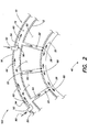
- the annular body 10 has an outer gas path platform 12, an outer body panel 16, and a circumferentially extending annular cavity 14 disposed between the outer gas path platform 12 and the outer body panel (illustrated in FIG. 2 ).
- the annular body 10 is formed as a single annular structure.
- the annular body 10 is manufactured in circumferentially defined sections that are combined to form the annular body 10.
- seals are typically disposed between adjacent sections to reduce leakage flow therebetween.
- the outer gas path platforms 12 and the outer body panel 16 are attached to one another by mechanical fasteners. In the embodiment shown in FIG.
- the annular cavity 14 has a height that is substantially uniform around the circumference of the annular body 10.
- the forward and aft sections of the annular body include one or more apertures that function as cooling gas leakage paths to permit flow of cooling air outside of the annular cavity 14 (not shown).
- Each of the plurality of fairings 20 extends radially between the inner gas path platform 30 and the outer gas path platform 12.
- the annular body 10 is disposed radially outside of the fairings 20.
- Each fairing 20 has a pair of faces extending between a leading edge 24 and a trailing edge 26.
- each fairing 20 includes a gas passage 22 extending radially through the fairing 20.
- the passage 22 provides a cooling air gas path from the cavity 14, through the inner annular platform 30, and into an inner cavity 32 defined in part by the inner gas path platform 30.
- one or more tie rods 80 and/or service lines are disposed within one or more of the plurality of fairings 20.
- the at least one nozzle 50 is mounted relative to the annular body 10, and extends through the outer body panel 16.
- the nozzle has an inlet orifice 52 disposed outside of the annular body 10 and an exit orifice 54 disposed within the cavity 14.
- the nozzle 50 is shaped and oriented within the cavity 14 such that cooling gas passing through the nozzle 50 and into the cavity 14 exits the nozzle 50 in a substantially circumferential direction.
- FIG. 2 diagrammatically illustrates a plurality of nozzles 50, each having an approximately ninety degree (90°) turn.
- the present invention is not limited to nozzles 50 of this configuration, however.
- the geometry of the nozzles 50 may vary from nozzle to nozzle, for example, to accommodate structure within the cavity 14, improve circumferential gas flow, etc.
- the number of nozzles 50 may vary between applications, and is not limited.
- the nozzles are uniformly disposed circumferentially around the annular body 10.
- at least one nozzle 50 may be provided in each section. The cooling gas flow within the cavity 14 collectively exiting from the plurality of nozzles 50 creates a circumferentially directed cooling gas flow within the cavity 14 (illustrated in FIG. 2 ).
- a metering plate 28 having at least one orifice is disposed within the passage 22 of at least one of the fairings 20 and is configured to create a pressure drop across the orifices in the metering plate.
- the use of a metering plate 28 within a particular passage 22, and the characteristics of the metering plate are varied to suit particular applications.
- a metering plate 28 may be disposed in each fairing 20 and the characteristics of each metering plate are "tuned" to create uniform cooling gas flow through each of the fairings 20.
- the position of the metering plate 28 within each fairing 20 is the same.
- FIG. 2 illustrates the metering plates 28 disposed at or near a radially inner end of the fairings 20. In other embodiment, the position of the metering plate 28 is varied between fairings 20.
- hot core gas 200 flows through the first rotor stage 90, between the outer gas path platform 12 and the inner gas path platform 30, around each of the fairings 20, and through to the second rotor stage 95.
- gas flow 200 travels through the assembly 100, it causes each fairing 20 to increase in temperature.
- cooling air flow 60 is injected into the cavity 14 through the nozzles 50.
- the cooling air exiting the nozzles 50 is directed in a substantially circumferential direction within the cavity 14.
- the circumferentially traveling cooling air flow 60 created by the cooling air exiting the nozzles 50 increases the uniformity of the cooling around the circumference of the annular body 10.
- the increased uniformity of the cooling air flow within the annular body 10 also increases the uniformity of the cooling air flow through the fairings 20 (illustrated in FIG. 3B ), as compared to the prior art (illustrated in FIG. 3A ).
- the metering plates 28 disposed within the passages 22 further increase the uniformity of the cooling air flow through the fairing passages 22, and thereby increase the uniformity of cooling gas flow into the region radially inside of the stator assembly 100.
Landscapes
- Engineering & Computer Science (AREA)
- Mechanical Engineering (AREA)
- General Engineering & Computer Science (AREA)
- Physics & Mathematics (AREA)
- Fluid Mechanics (AREA)
- Turbine Rotor Nozzle Sealing (AREA)
Applications Claiming Priority (1)
| Application Number | Priority Date | Filing Date | Title |
|---|---|---|---|
| US12/474,822 US20100303610A1 (en) | 2009-05-29 | 2009-05-29 | Cooled gas turbine stator assembly |
Publications (2)
| Publication Number | Publication Date |
|---|---|
| EP2264282A2 true EP2264282A2 (de) | 2010-12-22 |
| EP2264282A3 EP2264282A3 (de) | 2013-10-23 |
Family
ID=42729427
Family Applications (1)
| Application Number | Title | Priority Date | Filing Date |
|---|---|---|---|
| EP10250997.3A Withdrawn EP2264282A3 (de) | 2009-05-29 | 2010-05-28 | Gekühlte Gasturbinenstatoranordnung |
Country Status (2)
| Country | Link |
|---|---|
| US (1) | US20100303610A1 (de) |
| EP (1) | EP2264282A3 (de) |
Cited By (3)
| Publication number | Priority date | Publication date | Assignee | Title |
|---|---|---|---|---|
| EP2907978A1 (de) * | 2014-02-14 | 2015-08-19 | United Technologies Corporation | Turbinenzwischengehäuse mit defniertem kühlmittelverteilungsfluss |
| EP2971612A4 (de) * | 2013-03-13 | 2017-01-04 | United Technologies Corporation | Motormittelturbinenrahmen-transferröhre zur kühlung eines niederdruckturbinengehäuses |
| EP4667706A3 (de) * | 2024-06-17 | 2026-02-25 | RTX Corporation | Luftkühlsystem für aussenplattform einer leitschaufelstruktur |
Families Citing this family (25)
| Publication number | Priority date | Publication date | Assignee | Title |
|---|---|---|---|---|
| US9279341B2 (en) * | 2011-09-22 | 2016-03-08 | Pratt & Whitney Canada Corp. | Air system architecture for a mid-turbine frame module |
| US8932011B2 (en) | 2011-10-06 | 2015-01-13 | United Technologies Corporation | Shaft assembly for a gas turbine engine |
| US9316117B2 (en) | 2012-01-30 | 2016-04-19 | United Technologies Corporation | Internally cooled spoke |
| US9217371B2 (en) | 2012-07-13 | 2015-12-22 | United Technologies Corporation | Mid-turbine frame with tensioned spokes |
| US9587514B2 (en) | 2012-07-13 | 2017-03-07 | United Technologies Corporation | Vane insertable tie rods with keyed connections |
| US9222413B2 (en) * | 2012-07-13 | 2015-12-29 | United Technologies Corporation | Mid-turbine frame with threaded spokes |
| US9010122B2 (en) | 2012-07-27 | 2015-04-21 | United Technologies Corporation | Turbine engine combustor and stator vane assembly |
| US20140186160A1 (en) * | 2012-12-29 | 2014-07-03 | United Technologies Corporation | Slider seal |
| US9617870B2 (en) | 2013-02-05 | 2017-04-11 | United Technologies Corporation | Bracket for mounting a stator guide vane arrangement to a strut in a turbine engine |
| GB201305432D0 (en) | 2013-03-26 | 2013-05-08 | Rolls Royce Plc | A gas turbine engine cooling arrangement |
| ES2716100T3 (es) | 2014-06-12 | 2019-06-10 | MTU Aero Engines AG | Carcasa intermedia para una turbina de gas y turbina de gas con dicha carcasa intermedia |
| US10392969B2 (en) | 2014-12-02 | 2019-08-27 | United Technologies Corporation | Moment accommodating fastener assembly |
| US9856750B2 (en) * | 2015-01-16 | 2018-01-02 | United Technologies Corporation | Cooling passages for a mid-turbine frame |
| US9732628B2 (en) * | 2015-03-20 | 2017-08-15 | United Technologies Corporation | Cooling passages for a mid-turbine frame |
| EP3320183B1 (de) | 2015-07-06 | 2021-11-10 | Siemens Energy Global GmbH & Co. KG | Turbinenstatorschaufel und/oder turbinenrotorschaufel mit einer kühlmassenstromeinstelleinrichtung und zugehöriges verfahren zum anpassen einer schaufel |
| US10443449B2 (en) | 2015-07-24 | 2019-10-15 | Pratt & Whitney Canada Corp. | Spoke mounting arrangement |
| CN107849937B (zh) | 2015-07-24 | 2020-06-19 | 普拉特-惠特尼加拿大公司 | 涡轮中间框架辐条冷却系统及方法 |
| US10247035B2 (en) | 2015-07-24 | 2019-04-02 | Pratt & Whitney Canada Corp. | Spoke locking architecture |
| DE102015215144B4 (de) * | 2015-08-07 | 2017-11-09 | MTU Aero Engines AG | Vorrichtung und Verfahren zum Beeinflussen der Temperaturen in Innenringsegmenten einer Gasturbine |
| US10273812B2 (en) | 2015-12-18 | 2019-04-30 | Pratt & Whitney Canada Corp. | Turbine rotor coolant supply system |
| US11549396B2 (en) | 2019-11-12 | 2023-01-10 | Pratt & Whitney Canada Corp. | Mid-turbine frame for gas turbine engine |
| US11698005B2 (en) | 2020-02-07 | 2023-07-11 | Raytheon Technologies Corporation | Flow diverter for mid-turbine frame cooling air delivery |
| FR3110201B1 (fr) * | 2020-05-15 | 2022-04-08 | Safran Aircraft Engines | Carter d’échappement de turbomachine |
| CN114198153B (zh) * | 2020-09-17 | 2024-05-03 | 中国航发商用航空发动机有限责任公司 | 涡轮叶片冷却系统及航空发动机 |
| US11473439B1 (en) * | 2021-09-23 | 2022-10-18 | General Electric Company | Gas turbine engine with hollow rotor in fluid communication with a balance piston cavity |
Citations (1)
| Publication number | Priority date | Publication date | Assignee | Title |
|---|---|---|---|---|
| US20080232953A1 (en) * | 2007-03-20 | 2008-09-25 | Snecma | Inter-turbine casing with cooling circuit, and turbofan comprising it |
Family Cites Families (21)
| Publication number | Priority date | Publication date | Assignee | Title |
|---|---|---|---|---|
| US4478551A (en) * | 1981-12-08 | 1984-10-23 | United Technologies Corporation | Turbine exhaust case design |
| US4770608A (en) * | 1985-12-23 | 1988-09-13 | United Technologies Corporation | Film cooled vanes and turbines |
| US4767268A (en) * | 1987-08-06 | 1988-08-30 | United Technologies Corporation | Triple pass cooled airfoil |
| US4890978A (en) * | 1988-10-19 | 1990-01-02 | Westinghouse Electric Corp. | Method and apparatus for vane segment support and alignment in combustion turbines |
| US4979872A (en) * | 1989-06-22 | 1990-12-25 | United Technologies Corporation | Bearing compartment support |
| US5117626A (en) * | 1990-09-04 | 1992-06-02 | Westinghouse Electric Corp. | Apparatus for cooling rotating blades in a gas turbine |
| US5141394A (en) * | 1990-10-10 | 1992-08-25 | Westinghouse Electric Corp. | Apparatus and method for supporting a vane segment in a gas turbine |
| US5273397A (en) * | 1993-01-13 | 1993-12-28 | General Electric Company | Turbine casing and radiation shield |
| US5387086A (en) * | 1993-07-19 | 1995-02-07 | General Electric Company | Gas turbine blade with improved cooling |
| US5498126A (en) * | 1994-04-28 | 1996-03-12 | United Technologies Corporation | Airfoil with dual source cooling |
| US5609467A (en) * | 1995-09-28 | 1997-03-11 | Cooper Cameron Corporation | Floating interturbine duct assembly for high temperature power turbine |
| DE19549202B4 (de) * | 1995-12-30 | 2006-05-04 | Robert Bosch Gmbh | Gleichrichterdiode |
| US5741117A (en) * | 1996-10-22 | 1998-04-21 | United Technologies Corporation | Method for cooling a gas turbine stator vane |
| US5702214A (en) * | 1996-11-07 | 1997-12-30 | Avibank Mfg., Inc. | Non-removable structural fastener assembly |
| US5848874A (en) * | 1997-05-13 | 1998-12-15 | United Technologies Corporation | Gas turbine stator vane assembly |
| US6508620B2 (en) * | 2001-05-17 | 2003-01-21 | Pratt & Whitney Canada Corp. | Inner platform impingement cooling by supply air from outside |
| JP4040556B2 (ja) * | 2003-09-04 | 2008-01-30 | 株式会社日立製作所 | ガスタービン設備及び冷却空気供給方法 |
| US6929445B2 (en) * | 2003-10-22 | 2005-08-16 | General Electric Company | Split flow turbine nozzle |
| DE10352089A1 (de) * | 2003-11-07 | 2005-06-09 | Alstom Technology Ltd | Verfahren zum Betreiben einer Turbomaschine, und Turbomaschine |
| JP2006037855A (ja) * | 2004-07-28 | 2006-02-09 | Mitsubishi Heavy Ind Ltd | 車室ケーシング及びガスタービン |
| US7798765B2 (en) * | 2007-04-12 | 2010-09-21 | United Technologies Corporation | Out-flow margin protection for a gas turbine engine |
-
2009
- 2009-05-29 US US12/474,822 patent/US20100303610A1/en not_active Abandoned
-
2010
- 2010-05-28 EP EP10250997.3A patent/EP2264282A3/de not_active Withdrawn
Patent Citations (1)
| Publication number | Priority date | Publication date | Assignee | Title |
|---|---|---|---|---|
| US20080232953A1 (en) * | 2007-03-20 | 2008-09-25 | Snecma | Inter-turbine casing with cooling circuit, and turbofan comprising it |
Cited By (6)
| Publication number | Priority date | Publication date | Assignee | Title |
|---|---|---|---|---|
| EP2971612A4 (de) * | 2013-03-13 | 2017-01-04 | United Technologies Corporation | Motormittelturbinenrahmen-transferröhre zur kühlung eines niederdruckturbinengehäuses |
| EP3348803A1 (de) | 2013-03-13 | 2018-07-18 | United Technologies Corporation | Motormittelturbinenrahmen-transferröhre zur kühlung eines niederdruckturbinengehäuses |
| US10087782B2 (en) | 2013-03-13 | 2018-10-02 | United Technologies Corporation | Engine mid-turbine frame transfer tube for low pressure turbine case cooling |
| EP2907978A1 (de) * | 2014-02-14 | 2015-08-19 | United Technologies Corporation | Turbinenzwischengehäuse mit defniertem kühlmittelverteilungsfluss |
| US9803501B2 (en) | 2014-02-14 | 2017-10-31 | United Technologies Corporation | Engine mid-turbine frame distributive coolant flow |
| EP4667706A3 (de) * | 2024-06-17 | 2026-02-25 | RTX Corporation | Luftkühlsystem für aussenplattform einer leitschaufelstruktur |
Also Published As
| Publication number | Publication date |
|---|---|
| US20100303610A1 (en) | 2010-12-02 |
| EP2264282A3 (de) | 2013-10-23 |
Similar Documents
| Publication | Publication Date | Title |
|---|---|---|
| EP2264282A2 (de) | Gekühlte Gasturbinenstatoranordnung | |
| US9759092B2 (en) | Casing cooling duct | |
| EP2702250B1 (de) | Verfahren zur herstellung einer mehrtafeligen aussenwand eines bauteils zur verwendung bei einem gasturbinenmotor | |
| US4522557A (en) | Cooling device for movable turbine blade collars | |
| EP3124746B1 (de) | Verfahren zur kühlung einer turbomaschinenkomponente und turbomaschinenkomponente | |
| US7527470B2 (en) | Stator turbine vane with improved cooling | |
| US20200240638A1 (en) | Film-cooled multi-walled structure with one or more indentations | |
| CN106255806A (zh) | 涡轮组件和相应的操作方法 | |
| US10731855B2 (en) | Combustor panel cooling arrangements | |
| US10378372B2 (en) | Turbine with cooled turbine guide vanes | |
| US20190186272A1 (en) | Engine component with cooling hole | |
| US20130011238A1 (en) | Cooled ring segment | |
| US10385727B2 (en) | Turbine nozzle with cooling channel coolant distribution plenum | |
| EP3156609B1 (de) | Turbinenleitschaufel mit auslassplenum für kühlluft. | |
| US20180051580A1 (en) | Turbine engine with a rim seal between the rotor and stator | |
| US10598026B2 (en) | Engine component wall with a cooling circuit | |
| US7011492B2 (en) | Turbine vane cooled by a reduced cooling air leak | |
| US11391161B2 (en) | Component for a turbine engine with a cooling hole | |
| JP4234650B2 (ja) | 冷却式ガスタービンエンジン羽根 | |
| EP3044440B1 (de) | Fluidinjektor zur kühlung eines gasturbinenmotorbauteils | |
| CN103518037B (zh) | 一种用于涡轮发动机涡轮的扇形喷管和涡轮发动机 | |
| US10590788B2 (en) | Device and method for influencing the temperatures in inner ring segments of a gas turbine | |
| CN115349047B (zh) | 涡轮机涡轮环和定子的组件 | |
| CN113710875B (zh) | 涡轮发动机叶片、相关涡轮发动机分配器和涡轮发动机 | |
| US20170328213A1 (en) | Engine component wall with a cooling circuit |
Legal Events
| Date | Code | Title | Description |
|---|---|---|---|
| PUAI | Public reference made under article 153(3) epc to a published international application that has entered the european phase |
Free format text: ORIGINAL CODE: 0009012 |
|
| AK | Designated contracting states |
Kind code of ref document: A2 Designated state(s): AL AT BE BG CH CY CZ DE DK EE ES FI FR GB GR HR HU IE IS IT LI LT LU LV MC MK MT NL NO PL PT RO SE SI SK SM TR |
|
| AX | Request for extension of the european patent |
Extension state: BA ME RS |
|
| PUAL | Search report despatched |
Free format text: ORIGINAL CODE: 0009013 |
|
| AK | Designated contracting states |
Kind code of ref document: A3 Designated state(s): AL AT BE BG CH CY CZ DE DK EE ES FI FR GB GR HR HU IE IS IT LI LT LU LV MC MK MT NL NO PL PT RO SE SI SK SM TR |
|
| AX | Request for extension of the european patent |
Extension state: BA ME RS |
|
| RIC1 | Information provided on ipc code assigned before grant |
Ipc: F01D 5/18 20060101AFI20130916BHEP Ipc: F01D 9/04 20060101ALI20130916BHEP Ipc: F01D 25/12 20060101ALI20130916BHEP Ipc: F01D 9/06 20060101ALI20130916BHEP |
|
| 17P | Request for examination filed |
Effective date: 20140416 |
|
| RBV | Designated contracting states (corrected) |
Designated state(s): AL AT BE BG CH CY CZ DE DK EE ES FI FR GB GR HR HU IE IS IT LI LT LU LV MC MK MT NL NO PL PT RO SE SI SK SM TR |
|
| RAP1 | Party data changed (applicant data changed or rights of an application transferred) |
Owner name: UNITED TECHNOLOGIES CORPORATION |
|
| STAA | Information on the status of an ep patent application or granted ep patent |
Free format text: STATUS: EXAMINATION IS IN PROGRESS |
|
| 17Q | First examination report despatched |
Effective date: 20180104 |
|
| STAA | Information on the status of an ep patent application or granted ep patent |
Free format text: STATUS: THE APPLICATION IS DEEMED TO BE WITHDRAWN |
|
| 18D | Application deemed to be withdrawn |
Effective date: 20180515 |