EP2264279A2 - Perforating apparatus for enhanced performance in high pressure wellbores - Google Patents
Perforating apparatus for enhanced performance in high pressure wellbores Download PDFInfo
- Publication number
- EP2264279A2 EP2264279A2 EP10163698A EP10163698A EP2264279A2 EP 2264279 A2 EP2264279 A2 EP 2264279A2 EP 10163698 A EP10163698 A EP 10163698A EP 10163698 A EP10163698 A EP 10163698A EP 2264279 A2 EP2264279 A2 EP 2264279A2
- Authority
- EP
- European Patent Office
- Prior art keywords
- gun body
- carrier gun
- perforating apparatus
- nanocomposite
- carrier
- Prior art date
- Legal status (The legal status is an assumption and is not a legal conclusion. Google has not performed a legal analysis and makes no representation as to the accuracy of the status listed.)
- Withdrawn
Links
- 239000002114 nanocomposite Substances 0.000 abstract description 64
- 230000000977 initiatory effect Effects 0.000 abstract description 4
- 238000005474 detonation Methods 0.000 abstract description 3
- 238000000034 method Methods 0.000 description 22
- 230000008569 process Effects 0.000 description 19
- XEEYBQQBJWHFJM-UHFFFAOYSA-N Iron Chemical compound [Fe] XEEYBQQBJWHFJM-UHFFFAOYSA-N 0.000 description 16
- 239000000463 material Substances 0.000 description 16
- 230000015572 biosynthetic process Effects 0.000 description 13
- 235000020637 scallop Nutrition 0.000 description 13
- 238000003466 welding Methods 0.000 description 13
- 241000237503 Pectinidae Species 0.000 description 9
- 230000001965 increasing effect Effects 0.000 description 9
- 229910052751 metal Inorganic materials 0.000 description 9
- 239000002184 metal Substances 0.000 description 9
- 229910052742 iron Inorganic materials 0.000 description 8
- 239000002086 nanomaterial Substances 0.000 description 8
- 238000007751 thermal spraying Methods 0.000 description 8
- 229910000640 Fe alloy Inorganic materials 0.000 description 6
- PXHVJJICTQNCMI-UHFFFAOYSA-N Nickel Chemical compound [Ni] PXHVJJICTQNCMI-UHFFFAOYSA-N 0.000 description 6
- 238000005336 cracking Methods 0.000 description 6
- 239000007789 gas Substances 0.000 description 6
- 230000008961 swelling Effects 0.000 description 6
- 229910045601 alloy Inorganic materials 0.000 description 5
- 239000000956 alloy Substances 0.000 description 5
- 239000002360 explosive Substances 0.000 description 5
- 241000237509 Patinopecten sp. Species 0.000 description 4
- 238000005275 alloying Methods 0.000 description 4
- 239000000470 constituent Substances 0.000 description 4
- 230000005484 gravity Effects 0.000 description 4
- ZOXJGFHDIHLPTG-UHFFFAOYSA-N Boron Chemical compound [B] ZOXJGFHDIHLPTG-UHFFFAOYSA-N 0.000 description 3
- OKTJSMMVPCPJKN-UHFFFAOYSA-N Carbon Chemical compound [C] OKTJSMMVPCPJKN-UHFFFAOYSA-N 0.000 description 3
- VYZAMTAEIAYCRO-UHFFFAOYSA-N Chromium Chemical compound [Cr] VYZAMTAEIAYCRO-UHFFFAOYSA-N 0.000 description 3
- ZOKXTWBITQBERF-UHFFFAOYSA-N Molybdenum Chemical compound [Mo] ZOKXTWBITQBERF-UHFFFAOYSA-N 0.000 description 3
- XUIMIQQOPSSXEZ-UHFFFAOYSA-N Silicon Chemical compound [Si] XUIMIQQOPSSXEZ-UHFFFAOYSA-N 0.000 description 3
- 229910052796 boron Inorganic materials 0.000 description 3
- 229910052799 carbon Inorganic materials 0.000 description 3
- 239000004568 cement Substances 0.000 description 3
- 229910052804 chromium Inorganic materials 0.000 description 3
- 239000011651 chromium Substances 0.000 description 3
- 238000009826 distribution Methods 0.000 description 3
- 230000002708 enhancing effect Effects 0.000 description 3
- WPBNNNQJVZRUHP-UHFFFAOYSA-L manganese(2+);methyl n-[[2-(methoxycarbonylcarbamothioylamino)phenyl]carbamothioyl]carbamate;n-[2-(sulfidocarbothioylamino)ethyl]carbamodithioate Chemical compound [Mn+2].[S-]C(=S)NCCNC([S-])=S.COC(=O)NC(=S)NC1=CC=CC=C1NC(=S)NC(=O)OC WPBNNNQJVZRUHP-UHFFFAOYSA-L 0.000 description 3
- 229910052750 molybdenum Inorganic materials 0.000 description 3
- 239000011733 molybdenum Substances 0.000 description 3
- 229910052759 nickel Inorganic materials 0.000 description 3
- 229910052758 niobium Inorganic materials 0.000 description 3
- 239000010955 niobium Substances 0.000 description 3
- GUCVJGMIXFAOAE-UHFFFAOYSA-N niobium atom Chemical compound [Nb] GUCVJGMIXFAOAE-UHFFFAOYSA-N 0.000 description 3
- 239000003921 oil Substances 0.000 description 3
- 229910052710 silicon Inorganic materials 0.000 description 3
- 239000010703 silicon Substances 0.000 description 3
- WFKWXMTUELFFGS-UHFFFAOYSA-N tungsten Chemical compound [W] WFKWXMTUELFFGS-UHFFFAOYSA-N 0.000 description 3
- 229910052721 tungsten Inorganic materials 0.000 description 3
- 239000010937 tungsten Substances 0.000 description 3
- 229910052720 vanadium Inorganic materials 0.000 description 3
- LEONUFNNVUYDNQ-UHFFFAOYSA-N vanadium atom Chemical compound [V] LEONUFNNVUYDNQ-UHFFFAOYSA-N 0.000 description 3
- 239000004215 Carbon black (E152) Substances 0.000 description 2
- ATUOYWHBWRKTHZ-UHFFFAOYSA-N Propane Chemical compound CCC ATUOYWHBWRKTHZ-UHFFFAOYSA-N 0.000 description 2
- 229910000831 Steel Inorganic materials 0.000 description 2
- 238000004031 devitrification Methods 0.000 description 2
- 238000010891 electric arc Methods 0.000 description 2
- 239000012530 fluid Substances 0.000 description 2
- 239000011521 glass Substances 0.000 description 2
- 229930195733 hydrocarbon Natural products 0.000 description 2
- 150000002430 hydrocarbons Chemical group 0.000 description 2
- 239000000155 melt Substances 0.000 description 2
- 239000005300 metallic glass Substances 0.000 description 2
- 238000012986 modification Methods 0.000 description 2
- 230000004048 modification Effects 0.000 description 2
- 230000035515 penetration Effects 0.000 description 2
- 239000007787 solid Substances 0.000 description 2
- 239000010959 steel Substances 0.000 description 2
- 230000009466 transformation Effects 0.000 description 2
- 238000000844 transformation Methods 0.000 description 2
- QVGXLLKOCUKJST-UHFFFAOYSA-N atomic oxygen Chemical compound [O] QVGXLLKOCUKJST-UHFFFAOYSA-N 0.000 description 1
- 244000309464 bull Species 0.000 description 1
- 239000000567 combustion gas Substances 0.000 description 1
- 238000000354 decomposition reaction Methods 0.000 description 1
- 230000003292 diminished effect Effects 0.000 description 1
- 238000005553 drilling Methods 0.000 description 1
- 238000010304 firing Methods 0.000 description 1
- 239000000446 fuel Substances 0.000 description 1
- 239000001257 hydrogen Substances 0.000 description 1
- 229910052739 hydrogen Inorganic materials 0.000 description 1
- 125000004435 hydrogen atom Chemical class [H]* 0.000 description 1
- 238000009434 installation Methods 0.000 description 1
- 239000003350 kerosene Substances 0.000 description 1
- 238000005551 mechanical alloying Methods 0.000 description 1
- 239000001301 oxygen Substances 0.000 description 1
- 229910052760 oxygen Inorganic materials 0.000 description 1
- 230000000149 penetrating effect Effects 0.000 description 1
- 239000000843 powder Substances 0.000 description 1
- 239000012255 powdered metal Substances 0.000 description 1
- 238000012545 processing Methods 0.000 description 1
- 239000001294 propane Substances 0.000 description 1
- QQONPFPTGQHPMA-UHFFFAOYSA-N propylene Natural products CC=C QQONPFPTGQHPMA-UHFFFAOYSA-N 0.000 description 1
- 125000004805 propylene group Chemical group [H]C([H])([H])C([H])([*:1])C([H])([H])[*:2] 0.000 description 1
- 230000009467 reduction Effects 0.000 description 1
- 230000000717 retained effect Effects 0.000 description 1
- 238000005096 rolling process Methods 0.000 description 1
- 239000006104 solid solution Substances 0.000 description 1
- 238000001330 spinodal decomposition reaction Methods 0.000 description 1
- 239000007921 spray Substances 0.000 description 1
- 238000012546 transfer Methods 0.000 description 1
- 238000010284 wire arc spraying Methods 0.000 description 1
Images



Classifications
-
- E—FIXED CONSTRUCTIONS
- E21—EARTH OR ROCK DRILLING; MINING
- E21B—EARTH OR ROCK DRILLING; OBTAINING OIL, GAS, WATER, SOLUBLE OR MELTABLE MATERIALS OR A SLURRY OF MINERALS FROM WELLS
- E21B43/00—Methods or apparatus for obtaining oil, gas, water, soluble or meltable materials or a slurry of minerals from wells
- E21B43/11—Perforators; Permeators
- E21B43/116—Gun or shaped-charge perforators
- E21B43/117—Shaped-charge perforators
Definitions
- the present invention is directed to a perforating apparatus for high pressure and high temperature applications.
- the perforating apparatus includes a carrier gun body having a plurality of radially reduced sections that have a nanocomposite outer layer.
- a charge holder is positioned within the carrier gun body.
- a plurality of shaped charges are supported by the charge holder.
- the shaped charges each have an initiation end and a discharge end and are positioned such that the discharge ends are disposed proximate the radially reduced sections of the carrier gun body.
- the nanocomposite material that forms all or part of the carrier gun body may be a nanostructured alloy such as a nanostructured iron based alloy.
- the iron based alloy may be derived from metallic glass.
- the alloying constituents of the iron based alloy may be selected from the group consisting of boron, carbon, chromium, iron, manganese, molybdenum, nickel, niobium, silicon, tungsten and vanadium.
- the nanocomposite layers may be applied to the carrier gun body by a thermal spraying process. In another embodiment, the nanocomposite layers may be applied to the carrier gun body by a welding process. The nanocomposite layers may be so applied (i.e. by thermal spraying or welding) to the radially reduced sections. In additional embodiments, the nanocomposite layers may be integral with the carrier gun body material.
- Figure 1 is a schematic illustration of an offshore oil and gas platform operating a perforating apparatus according to an embodiment of the present invention
- Figure 5 is a cross sectional view of a carrier gun body of a perforating apparatus according to an embodiment of the present invention
- figure 1 depicts a vertical well
- the shaped charge perforating apparatus of the present invention is equally well-suited for use in wells having other configurations including deviated wells, inclined wells, horizontal wells, multilateral wells and the like. Accordingly, use of directional terms such as “above”, “below”, “upper”, “lower” and the like are used for convenience in referring to the illustrations.
- figure 1 depicts an offshore operation
- the shaped charge perforating apparatus of the present invention is equally well-suited for use in onshore operations.
- optional thrust bearings 112 may be positioned between supports 108 at each end of carrier gun body 106 and devices 114 attached at each end of carrier gun body 106.
- Devices 114 may be tandems used to couple two guns to each other, a bull plug used to terminate a gun string, a firing head or any other type of device which may be attached to a carrier gun body 106 in a gun string. In this configuration, charges 102 are permitted to rotate within carrier gun body 106.
- Nanocomposite outer layers 154 have a strength that is greater than the strength of the metal forming the remainder of carrier gun body 150.
- the carrier gun body 150 may be formed from conventional steel while nanocomposite outer layers 154 are formed from a nanostructured material having nanosized features such as nanograined iron alloys including nanograined steels.
- a nanostructured material will include materials having features from 1 to 500 nanometers and more preferably materials having features from 1 to 100 nanometers.
- the weight percents of the alloying constituents are between about 0% and 4% boron, between about 0.1% and 8% carbon, between about 0.5% and 21% chromium, between about 55% and 95% iron, between about 0% and 3% manganese, between about 0.5% and 8% molybdenum, between about 0% and 5% nickel, between about 0% and 4% niobium, between about 0% and 2% silicon, between about 0% and 7% tungsten and between about 0% and 4% vanadium.
- the material of nanocomposite outer layers 154 may be formed using a self-assembling phenomenon in solid state transformations involving decomposition of single phase supersaturated solid solutions into multiphase nanoscale microstructures.
- the self-assembled solid state nanostructures can be prepared using a variety of techniques including spinodal decomposition, eutectoid transformations, glass devitrification and the like.
- the material of nanocomposite outer layers 154 may be formed by using mechanical alloying of powdered metals.
- the material of nanocomposite outer layers 154 is formed using a glass devitrification process wherein the alloying constituents of the iron based system are heat treated in a metallic glass state then devitrified into a material having the desired multiphase nanoscale grain structure.
- Nanocomposite outer layers 154 may be applied to or formed on carrier gun body 150 using a variety of processing techniques including thermal spraying processes, welding processes or other suitable techniques or may be integrally formed with carrier gun body 150.
- nanocomposite outer layers 154 may be applied to the carrier gun body 150 using a high velocity oxy fuel (HVOF) thermal spraying process that utilizes a combination of oxygen and one or more combustion gases such as hydrogen, propane, propylene, kerosene and the like to spray on the nanocomposite layer.
- HVOF high velocity oxy fuel
- twin wire arc spraying (TWAS) process may be used wherein two electrically opposed charged metal wires are fed together to produce a controlled arc at their intersection to form a molten metal which is atomized and propelled onto the carrier gun body 150 by jets of compressed air or gas to form the nanocomposite layer.
- TWAS twin wire arc spraying
- Carrier gun body 160 includes a plurality of radially reduced areas 162 which may represent scallops, recesses or bands such as those discussed above or other configurations in which the wall of carrier gun body 160 has certain thin wall portions.
- Each radially reduced area 162 as well as the area proximate each radially reduced area 162 has a nanocomposite outer layer 164 that increases the strength of carrier gun body 160, thereby enabling a perforating apparatus including carrier gun body 160 to be operable in high pressure and high temperature wellbores.
- nanocomposite outer layers 164 have a strength that is greater than the strength of the metal forming the remainder of carrier gun body 160 and may be formed from a nanostructured material having nanosized features such as the nanograined iron alloys discussed above. Nanocomposite outer layers 164 may be applied to or formed on carrier gun body 160 using a variety of processes such as those discussed above including thermal spraying and welding processes or may be integrally formed with carrier gun body 160.
- nanocomposite outer layers 164 in and around radially reduced areas 162 of carrier gun body 160 enables enhanced perforating performance in high pressure and high temperature wellbores by increasing the strength of carrier gun body 160.
- nanocomposite outer layers 164 increase the survivability of carrier gun body 160 following the perforation event by minimizing swelling, cracking, catastrophic rupturing or splitting of carrier gun body 160.
- nanocomposite outer layer 174 has a strength that is greater than the strength of the metal forming the remainder of carrier gun body 170 and may be formed from a nanostructured material having nanosized features such as the nanograined iron alloys discussed above. Nanocomposite outer layer 174 may be applied to or formed on carrier gun body 170 using a variety of processes such as those discussed above including thermal spraying and welding processes or may be integrally formed with carrier gun body 170.
- nanocomposite outer layer 174 of carrier gun body 170 enables enhanced perforating performance in high pressure and high temperature wellbores by increasing the strength of carrier gun body 170.
- nanocomposite outer layer 174 increases the survivability of carrier gun body 170 following the perforation event by minimizing swelling, cracking, catastrophic rupturing or splitting of carrier gun body 170.
- Carrier gun body 180 includes a plurality of radially reduced areas 182 which may represent scallops, recesses or bands such as those discussed above or other configurations in which the wall of carrier gun body 180 has certain thin wall portions.
- the inner surface of carrier gun body 180 has a nanocomposite layer 184 that increases the strength of carrier gun body 180, thereby enabling a perforating apparatus including carrier gun body 180 to be operable in high pressure and high temperature wellbores.
- nanocomposite inner layer 184 has a strength that is greater than the strength of the metal forming the remainder of carrier gun body 180 and may be formed from a nanostructured material having nanosized features such as the nanograined iron alloys discussed above. Nanocomposite inner layer 184 may be applied to or formed on carrier gun body 180 using a variety of processes such as those discussed above including thermal spraying and welding processes or may be integrally formed with carrier gun body 180.
- nanocomposite inner layer 184 of carrier gun body 180 enables enhanced perforating performance in high pressure and high temperature wellbores by increasing the strength of carrier gun body 180.
- nanocomposite inner layer 184 increases the survivability of carrier gun body 180 following the perforation event by minimizing swelling, cracking, catastrophic rupturing or splitting of carrier gun body 180.
Landscapes
- Life Sciences & Earth Sciences (AREA)
- Engineering & Computer Science (AREA)
- Geology (AREA)
- Mining & Mineral Resources (AREA)
- Physics & Mathematics (AREA)
- Environmental & Geological Engineering (AREA)
- Fluid Mechanics (AREA)
- General Life Sciences & Earth Sciences (AREA)
- Geochemistry & Mineralogy (AREA)
- Coating By Spraying Or Casting (AREA)
- Perforating, Stamping-Out Or Severing By Means Other Than Cutting (AREA)
- Other Surface Treatments For Metallic Materials (AREA)
Abstract
A perforating apparatus (50) includes a carrier gun body (52) having a plurality of radially reduced sections (54). The radially reduced sections (54) have a nanocomposite outer layer (72). A charge holder (62) is positioned within the carrier gun body (52). A plurality of shaped charges (56) are supported by the charge holder (62). The shaped charges (56) each have an initiation end and a discharge end. The discharge ends of the shaped charges (56) are disposed proximate the radially reduced sections (54) of the carrier gun body (52) such that the jets formed upon detonation of the shaped charges (56) travel through the radially reduced sections (54). The nanocomposite outer layers (72) of the radially reduced sections (54) enable enhanced performance of the perforating apparatus (50) in high pressure and high temperature wellbores.
Description
- This invention relates, in general, to an apparatus for perforating subterranean wellbores using shaped charges and, in particular, to a perforating apparatus for enhanced performance in high pressure and high temperature wellbores.
- Without limiting the scope of the present invention, its background will be described with reference to perforating a hydrocarbon bearing subterranean formation with a shaped charge perforating apparatus, as an example.
- After drilling the section of a subterranean wellbore that traverses a hydrocarbon bearing subterranean formation, individual lengths of metal tubulars are typically secured together to form a casing string that is positioned within the wellbore. This casing string increases the integrity of the wellbore and provides a path through which fluids from the formation may be produced to the surface. Conventionally, the casing string is cemented within the wellbore. To produce fluids into the casing string, hydraulic openings or perforations must be made through the casing string, the cement and a distance into the formation.
- Typically, these perforations are created by detonating a series of shaped charges located within one or more perforating guns that are deployed within the casing string to a position adjacent to the desired formation. Conventionally, the perforating guns are formed from a closed, fluid-tight hollow carrier gun body adapted to be lowered on a wire line or tubing conveyed into the wellbore. Disposed within the hollow carrier gun body is a charge holder that supports and positions the shaped charges in a selected spatial distribution. The shaped charges have conically constrained explosive material therein. A detonating cord that is used to detonate the shaped charges is positioned adjacent to the rear of the shaped charges. The detonating cord can be activated electronically or mechanically when the perforating gun has been positioned in the wellbore.
- In such closed, fluid-tight type gun bodies, the explosive jets produced upon detonation of the shaped charges penetrate the hollow carrier gun body before penetrating the casing wall of the wellbore and the adjacent formation. To reduce the resistance produced by the hollow carrier gun body and increase the depth of perforation penetration into the formation, the perforating gun body may be provided with scallops or other radially reduced sections such as bands that leave relatively thin wall portions through which the explosive jets pass. The scallops in the hollow carrier gun body must be positioned in a spatial distribution that corresponds to the spatial distribution of the shaped charges held within the gun body by the charge holder.
- It has been found, however, that the reduction in thickness of the carrier gun body at and near the scallops, limits the strength of the perforating guns. Thus, to perforate in certain high pressure and high temperature wellbores, perforating guns of a given outer diameter must have increased wall thickness and/or reduced scallop depth. In either case, the performance of such perforating guns is diminished. Specifically, use of a carrier gun body with increased wall thickness reduces the available volume within the carrier gun body which necessitates the use of smaller shaped charges. Likewise, use of a carrier gun body with reduced scallop depth limits the penetration depth of the perforations into the formation.
- A need has therefore arisen for a perforating apparatus that is operable for use in high pressure and high temperature wellbores that does not require a carrier gun body with increased wall thickness. A need has also arisen for such a perforating apparatus that is operable for use in high pressure and high temperature wellbores that does not require a carrier gun body with reduced scallop depth. Further, a need has arisen for such a perforating apparatus that is operable to achieve enhanced perforating performance in high pressure and high temperature wellbores.
- The present invention disclosed herein comprises a perforating apparatus for enhancing perforating performance in high pressure and high temperature wellbores. The perforating apparatus of the present invention is operable for use in high pressure and high temperature wellbores without requiring a carrier gun body with increased wall thickness. In addition, the perforating apparatus of the present invention is operable for use in high pressure and high temperature wellbores without requiring a carrier gun body with reduced scallop depth.
- In one aspect, the present invention is directed to a perforating apparatus for high pressure and high temperature applications. The perforating apparatus includes a carrier gun body having a plurality of radially reduced sections that have a nanocomposite outer layer. A charge holder is positioned within the carrier gun body. A plurality of shaped charges are supported by the charge holder. The shaped charges each have an initiation end and a discharge end and are positioned such that the discharge ends are disposed proximate the radially reduced sections of the carrier gun body.
- In one embodiment, the radially reduced sections of the carrier gun body are recesses. In another embodiment, the radially reduced sections of the carrier gun body are bands. In certain embodiments, the use of a nanocomposite outer layer is not limited to the radially reduced sections of the carrier gun body. For example, a portion of the carrier gun body proximate the radially reduced sections may have a nanocomposite outer layer. Likewise, the entire carrier gun body may have a nanocomposite outer layer. Alternatively or additionally, the carrier gun body may have a nanocomposite inner layer or may be formed entirely from a nanocomposite material.
- In one embodiment, the nanocomposite material that forms all or part of the carrier gun body may be a nanostructured alloy such as a nanostructured iron based alloy. In this embodiment, the iron based alloy may be derived from metallic glass. Also, in this embodiment, the alloying constituents of the iron based alloy may be selected from the group consisting of boron, carbon, chromium, iron, manganese, molybdenum, nickel, niobium, silicon, tungsten and vanadium.
- In one embodiment, the nanocomposite layers may be applied to the carrier gun body by a thermal spraying process. In another embodiment, the nanocomposite layers may be applied to the carrier gun body by a welding process. The nanocomposite layers may be so applied (i.e. by thermal spraying or welding) to the radially reduced sections. In additional embodiments, the nanocomposite layers may be integral with the carrier gun body material.
- In another aspect, the present invention is directed to a perforating apparatus for high pressure and high temperature applications. The perforating apparatus includes a carrier gun body having an outer surface that is at least partially formed from a nanocomposite material. A charge holder is positioned within the carrier and a plurality of shaped charges are supported by the charge holder.
- For a more complete understanding of the features and advantages of the present invention, reference is now made to the detailed description of the invention along with the accompanying figures in which corresponding numerals in the different figures refer to corresponding parts and in which:
-
Figure 1 is a schematic illustration of an offshore oil and gas platform operating a perforating apparatus according to an embodiment of the present invention; -
Figure 2 is partial cut away view of a perforating apparatus according to an embodiment of the present invention; -
Figure 3 is partial cut away view of a perforating apparatus according to an embodiment of the present invention; -
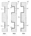
Figure 4 is a cross sectional view of a carrier gun body of a perforating apparatus according to an embodiment of the present invention; -
Figure 5 is a cross sectional view of a carrier gun body of a perforating apparatus according to an embodiment of the present invention; -
Figure 6 is a cross sectional view of a carrier gun body of a perforating apparatus according to an embodiment of the present invention; -
Figure 7 is a cross sectional view of a carrier gun body of a perforating apparatus according to an embodiment of the present invention; -
Figure 8 is a cross sectional view of a carrier gun body of a perforating apparatus according to an embodiment of the present invention; and -
Figure 9 is a cross sectional view of a carrier gun body of a perforating apparatus according to an embodiment of the present invention. - While the making and using of various embodiments of the present invention are discussed in detail below, it should be appreciated that the present invention provides many applicable inventive concepts which can be embodied in a wide variety of specific contexts. The specific embodiments discussed herein are merely illustrative of specific ways to make and use the invention, and do not delimit the scope of the present invention.
- Referring initially to
Figure 1 , a perforating apparatus of the present invention is operating from an offshore oil and gas platform is schematically illustrated and generally designated 10. Asemi-submersible platform 12 is centered over a submerged oil andgas formation 14 located belowsea floor 16. Asubsea conduit 18 extends fromdeck 20 ofplatform 12 towellhead installation 22 includingblowout preventers 24.Platform 12 has a hoistingapparatus 26 and aderrick 28 for raising and lowering pipe strings such as work sting 30. - A
wellbore 32 extends through the various earthstrata including formation 14. Acasing 34 is cemented withinwellbore 32 bycement 36.Work string 30 includes various tools including shapedcharge perforating apparatus 38 that is operable to enhance perforating performance in high pressure and high temperature wellbores. When it is desired to perforateformation 14,work string 30 is lowered throughcasing 34 until shapedcharge perforating apparatus 38 is positioned adjacent toformation 14. Thereafter, shapedcharge perforating apparatus 38 is fired by detonating the shaped charges that are disposed withincarrier gun body 40 and aligned withrecesses 42 formed in the outer surface ofcarrier gun body 40. In the present invention, at least the outer surface of eachrecess 42 includes a nanocomposite layer that increases the strength ofcarrier gun body 40 at the location of eachrecess 42. Use of the nanocomposite outer layer allowscarrier gun body 40 to have a relatively thin wall at the location of eachrecess 42, thereby enhancing perforating performance in high pressure and high temperature wellbores. As such, upon detonation, the liners of the shaped charges form jets that pass throughrecesses 42 and form a spaced series of perforations extending outwardly throughcasing 34,cement 36 and a desired depth intoformation 14. - Even though
figure 1 depicts a vertical well, it should be understood by those skilled in the art that the shaped charge perforating apparatus of the present invention is equally well-suited for use in wells having other configurations including deviated wells, inclined wells, horizontal wells, multilateral wells and the like. Accordingly, use of directional terms such as "above", "below", "upper", "lower" and the like are used for convenience in referring to the illustrations. Also, even thoughfigure 1 depicts an offshore operation, it should be understood by those skilled in the art that the shaped charge perforating apparatus of the present invention is equally well-suited for use in onshore operations. - Referring now to
figure 2 , therein is depicted a shaped charge perforating apparatus of the present invention that is generally designated 50.Perforating apparatus 50 includes acarrier gun body 52 made of a cylindrical sleeve having a plurality of radially reduced areas depicted as scallops or recesses 54. Radially aligned with each of therecesses 54 is a respective one of a plurality of shapedcharges 56. Each of the shapedcharges 56 includes an outer housing, such ashousing 58, and a liner, such asliner 60. Disposed between each housing and liner is a quantity of high explosive. - The shaped
charges 56 are retained withincarrier gun body 52 by acharge holder 62 which includes an outercharge holder sleeve 64, an innercharge holder sleeve 66. In this configuration,outer tube 64 supports the discharge ends ofshaped charges 56, whileinner tube 66 supports the initiation ends ofshaped charges 56. Disposed withininner tube 66 is adetonator cord 70, such as a Primacord, which is used to detonate shapedcharges 56. In the illustrated embodiment, the initiation ends ofshaped charges 56 extend across the central longitudinal axis of perforatingapparatus 50 allowingdetonator cord 70 to connect to the high explosive within shaped charges 56through an aperture defined at the apex of the housings of shapedcharges 56. - Each of the shaped
charges 56 is longitudinally and radially aligned with one of therecesses 54 incarrier gun body 52 when perforatingapparatus 50 is fully assembled. In the illustrated embodiment, shapedcharges 56 are arranged in a spiral pattern such that each shapedcharge 56 is disposed on its own level or height and is to be individually detonated so that only one shaped charge is fired at a time. It should be understood by those skilled in the art, however, that alternate arrangements of shaped charges may be used, including cluster type designs wherein more than one shaped charge is at the same level and is detonated at the same time, without departing from the principles of the present invention. As discussed below, each of therecesses 54 of perforatingapparatus 50 has a nanocompositeouter layer 72 that increases the strength ofcarrier gun body 52, thereby enabling perforatingapparatus 50 to be operable in high pressure and high temperature wellbores. - Referring now to
figure 3 , therein is depicted a shaped charge perforating apparatus of the present invention that is generally designated 100.Perforating apparatus 100 includes a plurality of shapedcharges 102 of which three are pictured.Shaped charges 102 are mounted within acharge holder 104 that is positioned within acarrier gun body 106. In the illustrated embodiment,charge holder 104 may including one or more longitudinal sections, each of which are rotatably supported incarrier gun body 106 by a pair ofsupports 108, only onesuch support 108 being visible infigure 2 . Each of thesupports 108 includes rolling elements orbearings 110 contacting the interior ofcarrier gun body 106. In addition,optional thrust bearings 112 may be positioned betweensupports 108 at each end ofcarrier gun body 106 anddevices 114 attached at each end ofcarrier gun body 106.Devices 114 may be tandems used to couple two guns to each other, a bull plug used to terminate a gun string, a firing head or any other type of device which may be attached to acarrier gun body 106 in a gun string. In this configuration,charges 102 are permitted to rotate withincarrier gun body 106. - In the illustrated embodiment, gravity is used to rotate
charges 102 withincarrier gun body 106 to the desired orientation. Specifically, by laterally offsetting the center of gravity of arotating assembly 118 that includescharge holder 104, shapedcharges 102 andweights 120,assembly 118 is biased by gravity to rotate to a specific position in which the center of gravity is located directly below the rotational axis. -
Carrier gun body 106 is provided with radially reduced portions depicted asbands 122.Bands 122 extend circumferentially aboutcarrier gun body 106 outwardly overlying each of thecharges 102. Thus, as each of the shapedcharges 102 rotates withincarrier gun body 106, they remain directed to shoot through one of thebands 122. As withrecesses 54 of perforatingapparatus 50 discussed above,bands 122 have a nanocompositeouter layer 124 that increases the strength ofcarrier gun body 106, thereby enabling perforatingapparatus 100 to be operable in high pressure and high temperature wellbores. - Referring now to
figure 4 , therein is depicted, in cross section, a portion of a carrier gun body of a perforating apparatus of the present invention that is generally designated 150.Carrier gun body 150 includes a plurality of radially reducedareas 152 which may represent scallops, recesses or bands such as those discussed above or other configurations in which the wall ofcarrier gun body 150 has certain thin wall portions. Each radially reducedarea 152 has a nanocompositeouter layer 154 that increases the strength ofcarrier gun body 150, thereby enabling a perforating apparatus includingcarrier gun body 150 to be operable in high pressure and high temperature wellbores. - Nanocomposite
outer layers 154 have a strength that is greater than the strength of the metal forming the remainder ofcarrier gun body 150. For example, thecarrier gun body 150 may be formed from conventional steel while nanocompositeouter layers 154 are formed from a nanostructured material having nanosized features such as nanograined iron alloys including nanograined steels. As used herein, a nanostructured material will include materials having features from 1 to 500 nanometers and more preferably materials having features from 1 to 100 nanometers. - Nanocomposite
outer layers 154 may be formed from an iron based alloy having alloying constituents selected from the group consisting of boron, carbon, chromium, iron, manganese, molybdenum, nickel, niobium, silicon, tungsten and vanadium. In one example, the weight percents of the alloying constituents are between about 0% and 4% boron, between about 0.1% and 8% carbon, between about 0.5% and 21% chromium, between about 55% and 95% iron, between about 0% and 3% manganese, between about 0.5% and 8% molybdenum, between about 0% and 5% nickel, between about 0% and 4% niobium, between about 0% and 2% silicon, between about 0% and 7% tungsten and between about 0% and 4% vanadium. - The material of nanocomposite
outer layers 154 may be formed using a self-assembling phenomenon in solid state transformations involving decomposition of single phase supersaturated solid solutions into multiphase nanoscale microstructures. The self-assembled solid state nanostructures can be prepared using a variety of techniques including spinodal decomposition, eutectoid transformations, glass devitrification and the like. Alternatively, the material of nanocompositeouter layers 154 may be formed by using mechanical alloying of powdered metals. Preferably, the material of nanocompositeouter layers 154 is formed using a glass devitrification process wherein the alloying constituents of the iron based system are heat treated in a metallic glass state then devitrified into a material having the desired multiphase nanoscale grain structure. - Nanocomposite
outer layers 154 may be applied to or formed oncarrier gun body 150 using a variety of processing techniques including thermal spraying processes, welding processes or other suitable techniques or may be integrally formed withcarrier gun body 150. For example, nanocompositeouter layers 154 may be applied to thecarrier gun body 150 using a high velocity oxy fuel (HVOF) thermal spraying process that utilizes a combination of oxygen and one or more combustion gases such as hydrogen, propane, propylene, kerosene and the like to spray on the nanocomposite layer. Likewise, a twin wire arc spraying (TWAS) process may be used wherein two electrically opposed charged metal wires are fed together to produce a controlled arc at their intersection to form a molten metal which is atomized and propelled onto thecarrier gun body 150 by jets of compressed air or gas to form the nanocomposite layer. - Alternatively, nanocomposite
outer layers 154 may be applied to or formed oncarrier gun body 150 using a variety of welding processes. For example, a plasma transfer arc welding (PTAW) process utilizes plasma to melt feedstock powder and form a fully dense and metallurgically bonded weld layer of the nanocomposite material on thecarrier gun body 150. Likewise, a gas metal arc welding (GMAW) process utilizes a continuous consumable wire electrode and a shielding gas which are fed through a welding torch such that an electric arc is transferred between the wire electrode and the surface of thecarrier gun body 150 and melts the wire to form the nanocomposite layer. Similarly, an open arc welding (OAW) process utilizes a continuous consumable wire electrode that is fed through a welding torch while an electric arc transferred between the wire electrode and thecarrier gun body 150 melts the wire to form the nanocomposite layer. - Use of nanocomposite
outer layers 154 in the radially reducedareas 152 ofcarrier gun body 150 enables enhanced perforating performance in high pressure and high temperature wellbores by increasing the strength ofcarrier gun body 150 at the radially reducedareas 152. In addition, nanocompositeouter layers 154 increase the survivability ofcarrier gun body 150 following the perforation event by minimizing swelling, cracking, catastrophic rupturing or splitting ofcarrier gun body 150. - Referring now to
figure 5 , therein is depicted, in cross section, a portion of a carrier gun body of a perforating apparatus of the present invention that is generally designated 160.Carrier gun body 160 includes a plurality of radially reducedareas 162 which may represent scallops, recesses or bands such as those discussed above or other configurations in which the wall ofcarrier gun body 160 has certain thin wall portions. Each radially reducedarea 162 as well as the area proximate each radially reducedarea 162 has a nanocompositeouter layer 164 that increases the strength ofcarrier gun body 160, thereby enabling a perforating apparatus includingcarrier gun body 160 to be operable in high pressure and high temperature wellbores. - As with nanocomposite
outer layers 154 discussed above, nanocompositeouter layers 164 have a strength that is greater than the strength of the metal forming the remainder ofcarrier gun body 160 and may be formed from a nanostructured material having nanosized features such as the nanograined iron alloys discussed above. Nanocompositeouter layers 164 may be applied to or formed oncarrier gun body 160 using a variety of processes such as those discussed above including thermal spraying and welding processes or may be integrally formed withcarrier gun body 160. - Use of nanocomposite
outer layers 164 in and around radially reducedareas 162 ofcarrier gun body 160 enables enhanced perforating performance in high pressure and high temperature wellbores by increasing the strength ofcarrier gun body 160. In addition, nanocompositeouter layers 164 increase the survivability ofcarrier gun body 160 following the perforation event by minimizing swelling, cracking, catastrophic rupturing or splitting ofcarrier gun body 160. - Referring now to
figure 6 , therein is depicted, in cross section, a portion of a carrier gun body of a perforating apparatus of the present invention that is generally designated 170.Carrier gun body 170 includes a plurality of radially reducedareas 172 which may represent scallops, recesses or bands such as those discussed above or other configurations in which the wall ofcarrier gun body 170 has certain thin wall portions. The outer surface ofcarrier gun body 170 has a nanocompositeouter layer 174 that increases the strength ofcarrier gun body 170, thereby enabling a perforating apparatus includingcarrier gun body 170 to be operable in high pressure and high temperature wellbores. - As with nanocomposite
outer layers outer layer 174 has a strength that is greater than the strength of the metal forming the remainder ofcarrier gun body 170 and may be formed from a nanostructured material having nanosized features such as the nanograined iron alloys discussed above. Nanocompositeouter layer 174 may be applied to or formed oncarrier gun body 170 using a variety of processes such as those discussed above including thermal spraying and welding processes or may be integrally formed withcarrier gun body 170. - Use of nanocomposite
outer layer 174 ofcarrier gun body 170 enables enhanced perforating performance in high pressure and high temperature wellbores by increasing the strength ofcarrier gun body 170. In addition, nanocompositeouter layer 174 increases the survivability ofcarrier gun body 170 following the perforation event by minimizing swelling, cracking, catastrophic rupturing or splitting ofcarrier gun body 170. - Referring now to
figure 7 , therein is depicted, in cross section, a portion of a carrier gun body of a perforating apparatus of the present invention that is generally designated 180.Carrier gun body 180 includes a plurality of radially reducedareas 182 which may represent scallops, recesses or bands such as those discussed above or other configurations in which the wall ofcarrier gun body 180 has certain thin wall portions. The inner surface ofcarrier gun body 180 has ananocomposite layer 184 that increases the strength ofcarrier gun body 180, thereby enabling a perforating apparatus includingcarrier gun body 180 to be operable in high pressure and high temperature wellbores. - As with nanocomposite
outer layers inner layer 184 has a strength that is greater than the strength of the metal forming the remainder ofcarrier gun body 180 and may be formed from a nanostructured material having nanosized features such as the nanograined iron alloys discussed above. Nanocompositeinner layer 184 may be applied to or formed oncarrier gun body 180 using a variety of processes such as those discussed above including thermal spraying and welding processes or may be integrally formed withcarrier gun body 180. - Use of nanocomposite
inner layer 184 ofcarrier gun body 180 enables enhanced perforating performance in high pressure and high temperature wellbores by increasing the strength ofcarrier gun body 180. In addition, nanocompositeinner layer 184 increases the survivability ofcarrier gun body 180 following the perforation event by minimizing swelling, cracking, catastrophic rupturing or splitting ofcarrier gun body 180. - Referring now to
figure 8 , therein is depicted, in cross section, a portion of a carrier gun body of a perforating apparatus of the present invention that is generally designated 190.Carrier gun body 190 includes a plurality of radially reducedareas 192 which may represent scallops, recesses or bands such as those discussed above or other configurations in which the wall ofcarrier gun body 190 has certain thin wall portions. Each radially reducedarea 192 has a nanocompositeouter layer 194 and the inner surface ofcarrier gun body 190 has ananocomposite layer 196 that increase the strength ofcarrier gun body 190, thereby enabling a perforating apparatus includingcarrier gun body 190 to be operable in high pressure and high temperature wellbores. - As with the nanocomposite outer layers discussed above, nanocomposite layers 194, 196 have a strength that is greater than the strength of the metal forming the remainder of
carrier gun body 190 and may be formed from a nanostructured material having nanosized features such as the nanograined iron alloys discussed above. Nanocomposite layers 194, 196 may be applied to or formed oncarrier gun body 190 using a variety of processes such as those discussed above including thermal spraying and welding processes or may be integrally formed withcarrier gun body 190. - Use of
nanocomposite layers carrier gun body 190 enables enhanced perforating performance in high pressure and high temperature wellbores by increasing the strength ofcarrier gun body 190. In addition, nanocomposite layers 194, 196 increase the survivability ofcarrier gun body 190 following the perforation event by minimizing swelling, cracking, catastrophic rupturing or splitting ofcarrier gun body 190. - Referring now to
figure 9 , therein is depicted, in cross section, a portion of a carrier gun body of a perforating apparatus of the present invention that is generally designated 200.Carrier gun body 200 is formed from ananocomposite material 202 that has a strength greater than a similarly dimensioned carrier gun body formed from conventional materials, thereby enabling a perforating apparatus includingcarrier gun body 200 to be operable in high pressure and high temperature wellbores. As with the nanocomposite layers discussed above,nanocomposite material 202 may be formed from a nanostructured material having nanosized features such as the nanograined iron alloys discussed above. In addition to enhancing perforating performance,carrier gun body 200 formed fromnanocomposite material 202 increases the survivability ofcarrier gun body 200 following the perforation event by minimizing swelling, cracking, catastrophic rupturing or splitting ofcarrier gun body 200. - While this invention has been described with reference to illustrative embodiments, this description is not intended to be construed in a limiting sense. Various modifications and combinations of the illustrative embodiments as well as other embodiments of the invention, will be apparent to persons skilled in the art upon reference to the description. It is, therefore, intended that the appended claims encompass any such modifications or embodiments.
Claims (15)
- A perforating apparatus comprising:a carrier gun body having a plurality of radially reduced sections, the radially reduced sections having a nanocomposite outer layer;a charge holder positioned within the carrier gun body; anda plurality of shaped charges supported by the charge holder, the shaped charges each having an initiation end and a discharge end, the discharge ends being disposed proximate the radially reduced sections of the carrier gun body.
- A perforating apparatus as claimed in claim 1, wherein the radially reduced sections further comprise recesses or bands.
- A perforating apparatus as claimed in claim 1 or 2, wherein at least a portion of the carrier gun body proximate the radially reduced sections further comprises a nanocomposite outer layer.
- A perforating apparatus as claimed in any of the predecing claims, wherein the carrier gun body further comprises a nanocomposite outer layer.
- A perforating apparatus as claimed in any of the preceding claims, wherein the carrier gun body further comprises a nanocomposite inner layer.
- A perforating apparatus comprising:a carrier gun body having a surface, the surface at least partially formed from a nanocomposite material;a charge holder positioned within the carrier; anda plurality of shaped charges supported by the charge holder.
- A perforating apparatus as claimed in claim 6, wherein the carrier gun body has a plurality of radially reduced sections and wherein the nanocomposite material forms an outer surface of the radially reduced sections of the carrier gun body.
- A perforating apparatus as claimed in claim 6 or 7, wherein the nanocomposite material forms an outer surface of at least a portion of the carrier gun body proximate the radially reduced sections.
- A perforating apparatus as claimed in any of claims 6 to 8, wherein the surface of the carrier gun body further comprises an outer surface and/or an inner surface.
- A perforating apparatus as claimed in any of claims 6 to 9, wherein the carrier gun body is entirely formed from nanocomposite material.
- A perforating apparatus as claimed in any of the preceding claims, wherein the nanocomposite material further comprises a nanostructured alloy.
- A perforating apparatus as claimed in any of claims 1 to 11, wherein the nanocomposite material further comprises an iron based alloy, and preferably wherein the iron based alloy is derived from a metallic glass, and/or preferably wherein alloying constituents of the iron based alloy are selected from the group consisting of boron, carbon, chromium, iron, manganese, molybdenum, nickel, niobium, silicon, tungsten and vanadium.
- A perforating apparatus as claimed in any of the preceding claims, wherein the nanocomposite is applied to the carrier gun body by a thermal spraying process.
- A perforating apparatus as claimed in any of claims 1 to 12, wherein the nanocomposite is applied to the carrier gun body by a welding process.
- A perforating apparatus as claimed in any of claims 1 to 12, wherein the nanocomposite is integral with the carrier gun body material.
Applications Claiming Priority (1)
| Application Number | Priority Date | Filing Date | Title |
|---|---|---|---|
| US12/473,569 US20100300750A1 (en) | 2009-05-28 | 2009-05-28 | Perforating Apparatus for Enhanced Performance in High Pressure Wellbores |
Publications (1)
| Publication Number | Publication Date |
|---|---|
| EP2264279A2 true EP2264279A2 (en) | 2010-12-22 |
Family
ID=42321175
Family Applications (1)
| Application Number | Title | Priority Date | Filing Date |
|---|---|---|---|
| EP10163698A Withdrawn EP2264279A2 (en) | 2009-05-28 | 2010-05-24 | Perforating apparatus for enhanced performance in high pressure wellbores |
Country Status (6)
| Country | Link |
|---|---|
| US (1) | US20100300750A1 (en) |
| EP (1) | EP2264279A2 (en) |
| JP (1) | JP2010281195A (en) |
| CN (1) | CN101899966A (en) |
| AR (1) | AR076933A1 (en) |
| MX (1) | MX2010005775A (en) |
Cited By (2)
| Publication number | Priority date | Publication date | Assignee | Title |
|---|---|---|---|---|
| WO2016036358A1 (en) * | 2014-09-03 | 2016-03-10 | Halliburton Energy Services, Inc. | Perforating systems with insensitive high explosive |
| WO2016036357A1 (en) * | 2014-09-03 | 2016-03-10 | Halliburton Energy Services, Inc. | Perforating systems with insensitive high explosive |
Families Citing this family (38)
| Publication number | Priority date | Publication date | Assignee | Title |
|---|---|---|---|---|
| US8919461B2 (en) * | 2010-07-21 | 2014-12-30 | Baker Hughes Incorporated | Well tool having a nanoparticle reinforced metallic coating |
| US9284824B2 (en) | 2011-04-21 | 2016-03-15 | Halliburton Energy Services, Inc. | Method and apparatus for expendable tubing-conveyed perforating gun |
| US8794335B2 (en) * | 2011-04-21 | 2014-08-05 | Halliburton Energy Services, Inc. | Method and apparatus for expendable tubing-conveyed perforating gun |
| WO2013130092A1 (en) * | 2012-03-02 | 2013-09-06 | Halliburton Energy Services, Inc. | Perforating apparatus and method having internal load path |
| BR112013026097A2 (en) * | 2012-04-22 | 2016-12-27 | Halliburton Energy Services Inc | method for drilling a well casing, and wearable pipe-carried drill |
| US9926777B2 (en) | 2012-12-01 | 2018-03-27 | Halliburton Energy Services, Inc. | Protection of electronic devices used with perforating guns |
| US9238956B2 (en) | 2013-05-09 | 2016-01-19 | Halliburton Energy Services, Inc. | Perforating gun apparatus for generating perforations having variable penetration profiles |
| EP2946069A4 (en) * | 2013-05-09 | 2016-11-02 | Halliburton Energy Services Inc | Perforating gun apparatus for generating perforations having variable penetration profiles |
| US9702680B2 (en) | 2013-07-18 | 2017-07-11 | Dynaenergetics Gmbh & Co. Kg | Perforation gun components and system |
| CA2916015C (en) | 2013-08-30 | 2018-03-20 | Halliburton Energy Services, Inc. | Lwd resistivity imaging tool with adjustable sensor pads |
| WO2015102620A1 (en) * | 2013-12-31 | 2015-07-09 | Halliburton Energy Services, Inc. | Selective annealing process for perforation guns |
| US9810048B2 (en) * | 2015-09-23 | 2017-11-07 | Benteler Steel/Tube Gmbh | Perforating gun |
| CN105545261B (en) * | 2015-12-28 | 2018-07-03 | 北方斯伦贝谢油田技术(西安)有限公司 | The pressure break perforating bullet and its shaped charge material of a kind of oil/gas well |
| US9896915B2 (en) | 2016-04-25 | 2018-02-20 | Benteler Steel/Tube Gmbh | Outer tube for a perforating gun |
| US20180299036A1 (en) * | 2017-04-13 | 2018-10-18 | Chevron U.S.A. Inc. | High strength downhole tubulars and methods for forming and systems for using |
| CA3073997C (en) | 2017-09-14 | 2022-06-21 | DynaEnergetics Europe GmbH | Shaped charge liner, shaped charge for high temperature wellbore operations and method of perforating a wellbore using same |
| US10669821B2 (en) * | 2018-04-25 | 2020-06-02 | G&H Diversified Manufacturing Lp | Charge tube assembly |
| US11808093B2 (en) | 2018-07-17 | 2023-11-07 | DynaEnergetics Europe GmbH | Oriented perforating system |
| US11339614B2 (en) | 2020-03-31 | 2022-05-24 | DynaEnergetics Europe GmbH | Alignment sub and orienting sub adapter |
| USD1034879S1 (en) | 2019-02-11 | 2024-07-09 | DynaEnergetics Europe GmbH | Gun body |
| USD1010758S1 (en) | 2019-02-11 | 2024-01-09 | DynaEnergetics Europe GmbH | Gun body |
| CN109737844B (en) * | 2019-03-20 | 2021-04-13 | 福建省新华都工程有限责任公司 | Mine big gun hole explosive distance installation mechanism |
| CA3140643A1 (en) | 2019-05-16 | 2020-11-19 | Schlumberger Canada Limited | Modular perforation tool |
| WO2020249744A2 (en) | 2019-06-14 | 2020-12-17 | DynaEnergetics Europe GmbH | Perforating gun assembly with rotating shaped charge holder |
| US11946728B2 (en) | 2019-12-10 | 2024-04-02 | DynaEnergetics Europe GmbH | Initiator head with circuit board |
| WO2021185749A1 (en) | 2020-03-16 | 2021-09-23 | DynaEnergetics Europe GmbH | Tandem seal adapter with integrated tracer material |
| US11988049B2 (en) | 2020-03-31 | 2024-05-21 | DynaEnergetics Europe GmbH | Alignment sub and perforating gun assembly with alignment sub |
| USD1016958S1 (en) | 2020-09-11 | 2024-03-05 | Schlumberger Technology Corporation | Shaped charge frame |
| US11293271B1 (en) * | 2020-10-28 | 2022-04-05 | Halliburton Energy Services, Inc. | Low-profile adjustable fastener for charge orientation of a downhole perforating tool |
| US12252964B2 (en) | 2020-11-13 | 2025-03-18 | Schlumberger Technology Corporation | Large shaped charge perforation tool |
| WO2022104220A1 (en) * | 2020-11-13 | 2022-05-19 | Schlumberger Technology Corporation | Oriented-perforation tool |
| US11499401B2 (en) | 2021-02-04 | 2022-11-15 | DynaEnergetics Europe GmbH | Perforating gun assembly with performance optimized shaped charge load |
| WO2022167297A1 (en) | 2021-02-04 | 2022-08-11 | DynaEnergetics Europe GmbH | Perforating gun assembly with performance optimized shaped charge load |
| US11732556B2 (en) | 2021-03-03 | 2023-08-22 | DynaEnergetics Europe GmbH | Orienting perforation gun assembly |
| US12366142B2 (en) | 2021-03-03 | 2025-07-22 | DynaEnergetics Europe GmbH | Modular perforating gun system |
| RU2759024C9 (en) * | 2021-04-19 | 2021-12-15 | Игорь Моисеевич Рафалович | Shaped-charge perforator |
| US12253339B2 (en) | 2021-10-25 | 2025-03-18 | DynaEnergetics Europe GmbH | Adapter and shaped charge apparatus for optimized perforation jet |
| CN116163688B (en) * | 2023-04-26 | 2023-06-27 | 山东成林石油工程技术有限公司 | Device for exploiting oil gas by gas-water relay jet flow and application method |
Family Cites Families (4)
| Publication number | Priority date | Publication date | Assignee | Title |
|---|---|---|---|---|
| US6767419B1 (en) * | 2000-11-09 | 2004-07-27 | Bechtel Bwxt Idaho, Llc | Methods of forming hardened surfaces |
| US6497285B2 (en) * | 2001-03-21 | 2002-12-24 | Halliburton Energy Services, Inc. | Low debris shaped charge perforating apparatus and method for use of same |
| US7360599B2 (en) * | 2004-11-18 | 2008-04-22 | Halliburton Energy Services, Inc. | Debris reduction perforating apparatus and method for use of same |
| US8704134B2 (en) * | 2005-02-11 | 2014-04-22 | The Nanosteel Company, Inc. | High hardness/high wear resistant iron based weld overlay materials |
-
2009
- 2009-05-28 US US12/473,569 patent/US20100300750A1/en not_active Abandoned
-
2010
- 2010-05-24 EP EP10163698A patent/EP2264279A2/en not_active Withdrawn
- 2010-05-26 MX MX2010005775A patent/MX2010005775A/en not_active Application Discontinuation
- 2010-05-27 AR ARP100101840A patent/AR076933A1/en unknown
- 2010-05-28 JP JP2010122469A patent/JP2010281195A/en not_active Withdrawn
- 2010-05-28 CN CN2010101946205A patent/CN101899966A/en active Pending
Non-Patent Citations (1)
| Title |
|---|
| None |
Cited By (9)
| Publication number | Priority date | Publication date | Assignee | Title |
|---|---|---|---|---|
| WO2016036358A1 (en) * | 2014-09-03 | 2016-03-10 | Halliburton Energy Services, Inc. | Perforating systems with insensitive high explosive |
| WO2016036357A1 (en) * | 2014-09-03 | 2016-03-10 | Halliburton Energy Services, Inc. | Perforating systems with insensitive high explosive |
| GB2544665A (en) * | 2014-09-03 | 2017-05-24 | Halliburton Energy Services Inc | Perforating systems with insensitive high explosive |
| GB2544663A (en) * | 2014-09-03 | 2017-05-24 | Halliburton Energy Services Inc | Perforating systems with insensitive high explosive |
| US10126103B2 (en) | 2014-09-03 | 2018-11-13 | Halliburton Energy Services, Inc. | Perforating systems with insensitive high explosive |
| GB2544665B (en) * | 2014-09-03 | 2019-04-10 | Halliburton Energy Services Inc | Perforating systems with insensitive high explosive |
| GB2544663B (en) * | 2014-09-03 | 2019-04-10 | Halliburton Energy Services Inc | Perforating systems with insensitive high explosive |
| US10677572B2 (en) | 2014-09-03 | 2020-06-09 | Halliburton Energy Services, Inc. | Perforating systems with insensitive high explosive |
| US10746002B2 (en) | 2014-09-03 | 2020-08-18 | Halliburton Energy Services, Inc. | Perforating systems with insensitive high explosive |
Also Published As
| Publication number | Publication date |
|---|---|
| CN101899966A (en) | 2010-12-01 |
| AR076933A1 (en) | 2011-07-20 |
| US20100300750A1 (en) | 2010-12-02 |
| MX2010005775A (en) | 2010-11-29 |
| JP2010281195A (en) | 2010-12-16 |
Similar Documents
| Publication | Publication Date | Title |
|---|---|---|
| EP2264279A2 (en) | Perforating apparatus for enhanced performance in high pressure wellbores | |
| US9238956B2 (en) | Perforating gun apparatus for generating perforations having variable penetration profiles | |
| CA2790693C (en) | Shaped charge liner comprised of reactive materials | |
| US9133695B2 (en) | Degradable shaped charge and perforating gun system | |
| US9187990B2 (en) | Method of using a degradable shaped charge and perforating gun system | |
| US8336437B2 (en) | Perforating gun assembly and method for controlling wellbore pressure regimes during perforating | |
| US10538997B2 (en) | Extended jet perforating device | |
| US7246548B2 (en) | Well perforating gun | |
| US9612095B2 (en) | Composite shaped charges | |
| US7055421B2 (en) | Well perforating gun | |
| US6926096B2 (en) | Method for using a well perforating gun | |
| US9347119B2 (en) | Degradable high shock impedance material | |
| US7360587B2 (en) | Debris reduction perforating apparatus | |
| WO2014182304A1 (en) | Perforating gun apparatus for generating perforations having variable penetration profiles | |
| US20060102352A1 (en) | Debris reduction perforating apparatus and method for use of same | |
| US10337299B2 (en) | Perforating apparatus and method having internal load path | |
| WO2013033535A2 (en) | Degradable high shock impedance material |
Legal Events
| Date | Code | Title | Description |
|---|---|---|---|
| PUAI | Public reference made under article 153(3) epc to a published international application that has entered the european phase |
Free format text: ORIGINAL CODE: 0009012 |
|
| AK | Designated contracting states |
Kind code of ref document: A2 Designated state(s): AL AT BE BG CH CY CZ DE DK EE ES FI FR GB GR HR HU IE IS IT LI LT LU LV MC MK MT NL NO PL PT RO SE SI SK SM TR |
|
| AX | Request for extension of the european patent |
Extension state: BA ME RS |
|
| STAA | Information on the status of an ep patent application or granted ep patent |
Free format text: STATUS: THE APPLICATION IS DEEMED TO BE WITHDRAWN |
|
| 18D | Application deemed to be withdrawn |
Effective date: 20121201 |