EP2264224A1 - Apparatus for depositing a thin film of material on a substrate and regeneration process for such an apparatus - Google Patents
Apparatus for depositing a thin film of material on a substrate and regeneration process for such an apparatus Download PDFInfo
- Publication number
- EP2264224A1 EP2264224A1 EP09305569A EP09305569A EP2264224A1 EP 2264224 A1 EP2264224 A1 EP 2264224A1 EP 09305569 A EP09305569 A EP 09305569A EP 09305569 A EP09305569 A EP 09305569A EP 2264224 A1 EP2264224 A1 EP 2264224A1
- Authority
- EP
- European Patent Office
- Prior art keywords
- cryogenic
- gaseous precursor
- vacuum chamber
- pressure
- trap means
- Prior art date
- Legal status (The legal status is an assumption and is not a legal conclusion. Google has not performed a legal analysis and makes no representation as to the accuracy of the status listed.)
- Granted
Links
- 239000000758 substrate Substances 0.000 title claims abstract description 46
- 230000008929 regeneration Effects 0.000 title claims abstract description 34
- 238000011069 regeneration method Methods 0.000 title claims abstract description 34
- 239000000463 material Substances 0.000 title claims abstract description 30
- 238000000034 method Methods 0.000 title claims abstract description 29
- 238000000151 deposition Methods 0.000 title claims abstract description 23
- 239000010409 thin film Substances 0.000 title claims abstract description 23
- 239000002243 precursor Substances 0.000 claims abstract description 98
- 238000005086 pumping Methods 0.000 claims abstract description 63
- 230000001105 regulatory effect Effects 0.000 claims abstract description 43
- QGZKDVFQNNGYKY-UHFFFAOYSA-N Ammonia Chemical compound N QGZKDVFQNNGYKY-UHFFFAOYSA-N 0.000 claims description 41
- 238000001451 molecular beam epitaxy Methods 0.000 claims description 23
- 229910021529 ammonia Inorganic materials 0.000 claims description 20
- 239000012530 fluid Substances 0.000 claims description 19
- 150000001875 compounds Chemical class 0.000 claims description 11
- 239000004065 semiconductor Substances 0.000 claims description 8
- 238000003795 desorption Methods 0.000 claims description 6
- 230000000295 complement effect Effects 0.000 claims description 5
- 238000010438 heat treatment Methods 0.000 claims description 5
- 235000012431 wafers Nutrition 0.000 claims description 3
- 239000005022 packaging material Substances 0.000 description 17
- IJGRMHOSHXDMSA-UHFFFAOYSA-N Atomic nitrogen Chemical compound N#N IJGRMHOSHXDMSA-UHFFFAOYSA-N 0.000 description 13
- LYCAIKOWRPUZTN-UHFFFAOYSA-N Ethylene glycol Chemical compound OCCO LYCAIKOWRPUZTN-UHFFFAOYSA-N 0.000 description 6
- 229910052757 nitrogen Inorganic materials 0.000 description 6
- 239000007789 gas Substances 0.000 description 5
- 239000007788 liquid Substances 0.000 description 5
- GYHNNYVSQQEPJS-UHFFFAOYSA-N Gallium Chemical compound [Ga] GYHNNYVSQQEPJS-UHFFFAOYSA-N 0.000 description 4
- JMASRVWKEDWRBT-UHFFFAOYSA-N Gallium nitride Chemical compound [Ga]#N JMASRVWKEDWRBT-UHFFFAOYSA-N 0.000 description 4
- 229910052733 gallium Inorganic materials 0.000 description 4
- 229910002601 GaN Inorganic materials 0.000 description 3
- XUIMIQQOPSSXEZ-UHFFFAOYSA-N Silicon Chemical compound [Si] XUIMIQQOPSSXEZ-UHFFFAOYSA-N 0.000 description 3
- 229910052782 aluminium Inorganic materials 0.000 description 3
- XAGFODPZIPBFFR-UHFFFAOYSA-N aluminium Chemical compound [Al] XAGFODPZIPBFFR-UHFFFAOYSA-N 0.000 description 3
- 230000007423 decrease Effects 0.000 description 3
- WGCNASOHLSPBMP-UHFFFAOYSA-N hydroxyacetaldehyde Natural products OCC=O WGCNASOHLSPBMP-UHFFFAOYSA-N 0.000 description 3
- 229910052751 metal Inorganic materials 0.000 description 3
- 239000002184 metal Substances 0.000 description 3
- 229910052710 silicon Inorganic materials 0.000 description 3
- 239000010703 silicon Substances 0.000 description 3
- 150000004767 nitrides Chemical class 0.000 description 2
- 238000010792 warming Methods 0.000 description 2
- 229910017083 AlN Inorganic materials 0.000 description 1
- PIGFYZPCRLYGLF-UHFFFAOYSA-N Aluminum nitride Chemical compound [Al]#N PIGFYZPCRLYGLF-UHFFFAOYSA-N 0.000 description 1
- 239000004411 aluminium Substances 0.000 description 1
- 230000033228 biological regulation Effects 0.000 description 1
- 238000005229 chemical vapour deposition Methods 0.000 description 1
- 238000011109 contamination Methods 0.000 description 1
- 230000001276 controlling effect Effects 0.000 description 1
- 238000001816 cooling Methods 0.000 description 1
- 229910003460 diamond Inorganic materials 0.000 description 1
- 239000010432 diamond Substances 0.000 description 1
- 238000000407 epitaxy Methods 0.000 description 1
- 230000001939 inductive effect Effects 0.000 description 1
- 238000004020 luminiscence type Methods 0.000 description 1
- 238000005121 nitriding Methods 0.000 description 1
- 229910000069 nitrogen hydride Inorganic materials 0.000 description 1
- 239000010980 sapphire Substances 0.000 description 1
- 229910052594 sapphire Inorganic materials 0.000 description 1
- HBMJWWWQQXIZIP-UHFFFAOYSA-N silicon carbide Chemical compound [Si+]#[C-] HBMJWWWQQXIZIP-UHFFFAOYSA-N 0.000 description 1
- 229910010271 silicon carbide Inorganic materials 0.000 description 1
- 238000007725 thermal activation Methods 0.000 description 1
Images
Classifications
-
- C—CHEMISTRY; METALLURGY
- C30—CRYSTAL GROWTH
- C30B—SINGLE-CRYSTAL GROWTH; UNIDIRECTIONAL SOLIDIFICATION OF EUTECTIC MATERIAL OR UNIDIRECTIONAL DEMIXING OF EUTECTOID MATERIAL; REFINING BY ZONE-MELTING OF MATERIAL; PRODUCTION OF A HOMOGENEOUS POLYCRYSTALLINE MATERIAL WITH DEFINED STRUCTURE; SINGLE CRYSTALS OR HOMOGENEOUS POLYCRYSTALLINE MATERIAL WITH DEFINED STRUCTURE; AFTER-TREATMENT OF SINGLE CRYSTALS OR A HOMOGENEOUS POLYCRYSTALLINE MATERIAL WITH DEFINED STRUCTURE; APPARATUS THEREFOR
- C30B23/00—Single-crystal growth by condensing evaporated or sublimed materials
- C30B23/02—Epitaxial-layer growth
-
- C—CHEMISTRY; METALLURGY
- C23—COATING METALLIC MATERIAL; COATING MATERIAL WITH METALLIC MATERIAL; CHEMICAL SURFACE TREATMENT; DIFFUSION TREATMENT OF METALLIC MATERIAL; COATING BY VACUUM EVAPORATION, BY SPUTTERING, BY ION IMPLANTATION OR BY CHEMICAL VAPOUR DEPOSITION, IN GENERAL; INHIBITING CORROSION OF METALLIC MATERIAL OR INCRUSTATION IN GENERAL
- C23C—COATING METALLIC MATERIAL; COATING MATERIAL WITH METALLIC MATERIAL; SURFACE TREATMENT OF METALLIC MATERIAL BY DIFFUSION INTO THE SURFACE, BY CHEMICAL CONVERSION OR SUBSTITUTION; COATING BY VACUUM EVAPORATION, BY SPUTTERING, BY ION IMPLANTATION OR BY CHEMICAL VAPOUR DEPOSITION, IN GENERAL
- C23C14/00—Coating by vacuum evaporation, by sputtering or by ion implantation of the coating forming material
- C23C14/22—Coating by vacuum evaporation, by sputtering or by ion implantation of the coating forming material characterised by the process of coating
- C23C14/56—Apparatus specially adapted for continuous coating; Arrangements for maintaining the vacuum, e.g. vacuum locks
-
- C—CHEMISTRY; METALLURGY
- C23—COATING METALLIC MATERIAL; COATING MATERIAL WITH METALLIC MATERIAL; CHEMICAL SURFACE TREATMENT; DIFFUSION TREATMENT OF METALLIC MATERIAL; COATING BY VACUUM EVAPORATION, BY SPUTTERING, BY ION IMPLANTATION OR BY CHEMICAL VAPOUR DEPOSITION, IN GENERAL; INHIBITING CORROSION OF METALLIC MATERIAL OR INCRUSTATION IN GENERAL
- C23C—COATING METALLIC MATERIAL; COATING MATERIAL WITH METALLIC MATERIAL; SURFACE TREATMENT OF METALLIC MATERIAL BY DIFFUSION INTO THE SURFACE, BY CHEMICAL CONVERSION OR SUBSTITUTION; COATING BY VACUUM EVAPORATION, BY SPUTTERING, BY ION IMPLANTATION OR BY CHEMICAL VAPOUR DEPOSITION, IN GENERAL
- C23C16/00—Chemical coating by decomposition of gaseous compounds, without leaving reaction products of surface material in the coating, i.e. chemical vapour deposition [CVD] processes
- C23C16/44—Chemical coating by decomposition of gaseous compounds, without leaving reaction products of surface material in the coating, i.e. chemical vapour deposition [CVD] processes characterised by the method of coating
- C23C16/4401—Means for minimising impurities, e.g. dust, moisture or residual gas, in the reaction chamber
- C23C16/4408—Means for minimising impurities, e.g. dust, moisture or residual gas, in the reaction chamber by purging residual gases from the reaction chamber or gas lines
-
- C—CHEMISTRY; METALLURGY
- C23—COATING METALLIC MATERIAL; COATING MATERIAL WITH METALLIC MATERIAL; CHEMICAL SURFACE TREATMENT; DIFFUSION TREATMENT OF METALLIC MATERIAL; COATING BY VACUUM EVAPORATION, BY SPUTTERING, BY ION IMPLANTATION OR BY CHEMICAL VAPOUR DEPOSITION, IN GENERAL; INHIBITING CORROSION OF METALLIC MATERIAL OR INCRUSTATION IN GENERAL
- C23C—COATING METALLIC MATERIAL; COATING MATERIAL WITH METALLIC MATERIAL; SURFACE TREATMENT OF METALLIC MATERIAL BY DIFFUSION INTO THE SURFACE, BY CHEMICAL CONVERSION OR SUBSTITUTION; COATING BY VACUUM EVAPORATION, BY SPUTTERING, BY ION IMPLANTATION OR BY CHEMICAL VAPOUR DEPOSITION, IN GENERAL
- C23C16/00—Chemical coating by decomposition of gaseous compounds, without leaving reaction products of surface material in the coating, i.e. chemical vapour deposition [CVD] processes
- C23C16/44—Chemical coating by decomposition of gaseous compounds, without leaving reaction products of surface material in the coating, i.e. chemical vapour deposition [CVD] processes characterised by the method of coating
- C23C16/455—Chemical coating by decomposition of gaseous compounds, without leaving reaction products of surface material in the coating, i.e. chemical vapour deposition [CVD] processes characterised by the method of coating characterised by the method used for introducing gases into reaction chamber or for modifying gas flows in reaction chamber
- C23C16/45502—Flow conditions in reaction chamber
-
- C—CHEMISTRY; METALLURGY
- C23—COATING METALLIC MATERIAL; COATING MATERIAL WITH METALLIC MATERIAL; CHEMICAL SURFACE TREATMENT; DIFFUSION TREATMENT OF METALLIC MATERIAL; COATING BY VACUUM EVAPORATION, BY SPUTTERING, BY ION IMPLANTATION OR BY CHEMICAL VAPOUR DEPOSITION, IN GENERAL; INHIBITING CORROSION OF METALLIC MATERIAL OR INCRUSTATION IN GENERAL
- C23C—COATING METALLIC MATERIAL; COATING MATERIAL WITH METALLIC MATERIAL; SURFACE TREATMENT OF METALLIC MATERIAL BY DIFFUSION INTO THE SURFACE, BY CHEMICAL CONVERSION OR SUBSTITUTION; COATING BY VACUUM EVAPORATION, BY SPUTTERING, BY ION IMPLANTATION OR BY CHEMICAL VAPOUR DEPOSITION, IN GENERAL
- C23C16/00—Chemical coating by decomposition of gaseous compounds, without leaving reaction products of surface material in the coating, i.e. chemical vapour deposition [CVD] processes
- C23C16/44—Chemical coating by decomposition of gaseous compounds, without leaving reaction products of surface material in the coating, i.e. chemical vapour deposition [CVD] processes characterised by the method of coating
- C23C16/455—Chemical coating by decomposition of gaseous compounds, without leaving reaction products of surface material in the coating, i.e. chemical vapour deposition [CVD] processes characterised by the method of coating characterised by the method used for introducing gases into reaction chamber or for modifying gas flows in reaction chamber
- C23C16/45523—Pulsed gas flow or change of composition over time
- C23C16/45525—Atomic layer deposition [ALD]
- C23C16/45544—Atomic layer deposition [ALD] characterized by the apparatus
-
- C—CHEMISTRY; METALLURGY
- C30—CRYSTAL GROWTH
- C30B—SINGLE-CRYSTAL GROWTH; UNIDIRECTIONAL SOLIDIFICATION OF EUTECTIC MATERIAL OR UNIDIRECTIONAL DEMIXING OF EUTECTOID MATERIAL; REFINING BY ZONE-MELTING OF MATERIAL; PRODUCTION OF A HOMOGENEOUS POLYCRYSTALLINE MATERIAL WITH DEFINED STRUCTURE; SINGLE CRYSTALS OR HOMOGENEOUS POLYCRYSTALLINE MATERIAL WITH DEFINED STRUCTURE; AFTER-TREATMENT OF SINGLE CRYSTALS OR A HOMOGENEOUS POLYCRYSTALLINE MATERIAL WITH DEFINED STRUCTURE; APPARATUS THEREFOR
- C30B23/00—Single-crystal growth by condensing evaporated or sublimed materials
- C30B23/002—Controlling or regulating
-
- C—CHEMISTRY; METALLURGY
- C30—CRYSTAL GROWTH
- C30B—SINGLE-CRYSTAL GROWTH; UNIDIRECTIONAL SOLIDIFICATION OF EUTECTIC MATERIAL OR UNIDIRECTIONAL DEMIXING OF EUTECTOID MATERIAL; REFINING BY ZONE-MELTING OF MATERIAL; PRODUCTION OF A HOMOGENEOUS POLYCRYSTALLINE MATERIAL WITH DEFINED STRUCTURE; SINGLE CRYSTALS OR HOMOGENEOUS POLYCRYSTALLINE MATERIAL WITH DEFINED STRUCTURE; AFTER-TREATMENT OF SINGLE CRYSTALS OR A HOMOGENEOUS POLYCRYSTALLINE MATERIAL WITH DEFINED STRUCTURE; APPARATUS THEREFOR
- C30B29/00—Single crystals or homogeneous polycrystalline material with defined structure characterised by the material or by their shape
- C30B29/10—Inorganic compounds or compositions
- C30B29/38—Nitrides
-
- C—CHEMISTRY; METALLURGY
- C30—CRYSTAL GROWTH
- C30B—SINGLE-CRYSTAL GROWTH; UNIDIRECTIONAL SOLIDIFICATION OF EUTECTIC MATERIAL OR UNIDIRECTIONAL DEMIXING OF EUTECTOID MATERIAL; REFINING BY ZONE-MELTING OF MATERIAL; PRODUCTION OF A HOMOGENEOUS POLYCRYSTALLINE MATERIAL WITH DEFINED STRUCTURE; SINGLE CRYSTALS OR HOMOGENEOUS POLYCRYSTALLINE MATERIAL WITH DEFINED STRUCTURE; AFTER-TREATMENT OF SINGLE CRYSTALS OR A HOMOGENEOUS POLYCRYSTALLINE MATERIAL WITH DEFINED STRUCTURE; APPARATUS THEREFOR
- C30B29/00—Single crystals or homogeneous polycrystalline material with defined structure characterised by the material or by their shape
- C30B29/10—Inorganic compounds or compositions
- C30B29/40—AIIIBV compounds wherein A is B, Al, Ga, In or Tl and B is N, P, As, Sb or Bi
- C30B29/403—AIII-nitrides
-
- Y—GENERAL TAGGING OF NEW TECHNOLOGICAL DEVELOPMENTS; GENERAL TAGGING OF CROSS-SECTIONAL TECHNOLOGIES SPANNING OVER SEVERAL SECTIONS OF THE IPC; TECHNICAL SUBJECTS COVERED BY FORMER USPC CROSS-REFERENCE ART COLLECTIONS [XRACs] AND DIGESTS
- Y10—TECHNICAL SUBJECTS COVERED BY FORMER USPC
- Y10T—TECHNICAL SUBJECTS COVERED BY FORMER US CLASSIFICATION
- Y10T29/00—Metal working
- Y10T29/49—Method of mechanical manufacture
- Y10T29/49718—Repairing
Abstract
Description
- The present invention relates to an apparatus for depositing a thin film of material on a substrate, and a regeneration process for such an apparatus.
- In particular, the present invention relates to apparatus like molecular beam epitaxy system.
- Epitaxial gallium nitride (GaN) semiconductor has shown very interesting semi conducting properties for high power and high frequency applications such as high luminescence LED or radiofrequence transistors.
- The epitaxy of thin layers of GaN can be done by two main techniques namely, Molecular Beam Epitaxy (MBE) and Metal Organic Chemical Vapor Deposition (MOCVD).
- In the case of molecular beam epitaxy technique, an element, Gallium for instance, is evaporated from a melted metal in an effusion cell and the nitrogen element can be supplied by molecular nitrogen cracked by a plasma source or from ammonia in gaseous state from a gas injector which decomposes chemically at the surface of the substrate by thermal activation.
- A molecular beam epitaxy device usually comprises a loading compartment wherein a substrate to be coated is introduced, a compartment wherein the substrate is dehydrated, a compartment wherein an operation of deoxidation of the substrate is performed, a growth chamber and trap means pumping the gaseous elements out of the growth chamber. We mean by "trap means", one or more active pumps associated with one or more cryogenic panels.
- The substrate, silicon for instance, is introduced in the growth chamber wherein a vacuum of about 10-8 Pascal is performed. The substrate is heated at a temperature between about 300°C and 1100°C. Then, gaseous precursor like ammonia is injected in the growth chamber and the atoms or molecules of elements or compounds in the effusion cell is heated to be evaporated. Gaseous ammonia reacts with the evaporated atoms or molecules of elements or compounds at the surface of the substrate to form an epitaxial layer of GaN, for example.
- A part of the gaseous precursor which is not cracked during the growth process is trapped on a cryogenic panel covering the inner surface of the lateral wall of the growth chamber and surrounding the process area, for example.
- The amount of frozen precursor on the cryogenic panel increases with the number of process runs inducing an extra increase of partial pressure of precursor in the system. Additionally, this precursor ice may clog or disturb system components such as moving parts, robots and gauges.
- To avoid these issues, it is then necessary to regenerate the cryogenic panels.
- The frozen precursor is re-evaporate by warming up the cryogenic panels. This can be done simply by limiting or switching off the cryogenic source therefore reducing or stopping the circulation of liquid nitrogen in the cryogenic panels.
- As the panels warming up to the temperature of the surrounding, precursor sublimates and the gaseous precursor is pumped out of the growth chamber by the trap means.
- However, the partial pressure of gaseous precursor increases exponentially with the temperature rise. The gaseous precursor partial pressure is high if the desorbed flow of gaseous precursor is high compared to the pumping capacity of the trap means. If the pumping capacity of the trap means is not efficient, the gaseous precursor partial pressure increases exponentially to a maximum of pressure.
- The high pressure of gaseous precursor during the regeneration process may damage heaters of effusion cells and substrate holder and also react with hot source materials like gallium or aluminum used in the semiconductor device structure, and in general all elements that can be sensitive to nitriding.
- Cooling down the material sources would prevent thermally activated reaction, but these sources can usually not be switched off during regeneration process for differential thermal expansion reasons like typically for aluminium source, or to prevent a contamination or pollution of a cold source surface, or because they can be the sources of heat to warm-up the system.
- In addition, when the partial pressure of gaseous precursor increases exponentially to high pressure, it could be dangerous for the operator manipulating the molecular beam epitaxy system.
- One object of the present invention is to provide an apparatus for depositing a thin film of material on a substrate wherein the gaseous precursor partial pressure is controlled during the regeneration of the cryogenic panels of the vacuum chamber.
- An other object of the present invention is to provide a regeneration process enabling to evacuate the gaseous precursor initially trapped on the cryogenic panels of the vacuum chamber, out of said vacuum chamber, and in a controlled and automatic manner.
- It is possible to not go over a given limit of pressure or determined pressure in order to avoid the saturation of the trap means and to nitride hot components like effusion cell or hot materials, for example. Abrupt increase of gaseous precursor pressure is avoided.
- To this end, the invention concerns an apparatus for depositing a thin film of material on a substrate comprising:
- a vacuum chamber,
- a sample holder disposed inside said vacuum chamber, said sample holder being able to support said substrate,
- a gas injector able to inject a gaseous precursor into the vacuum chamber, a part of said gaseous precursor being able to react at the surface of the substrate,
- at least one cryogenic panel positioned inside the vacuum chamber and able to adsorb a part of said gaseous precursor which has not reacted at the surface of the substrate, and to release said adsorbed gaseous precursor,
- first trap means connected to said vacuum chamber and able to trap a part of said gaseous precursor released by said cryogenic panel, said first trap means having a fixed pumping capacity S1.
- According to the invention, the apparatus for depositing a thin film of material on a substrate comprises:
- second trap means able to trap an other part of said gaseous precursor released by said cryogenic panel and having a variable pumping capacity S2 able to be regulated in function of the gaseous precursor partial pressure,
- said first and second trap means providing a total pumping capacity S = S1 + S2 sufficient to maintain the gaseous precursor partial pressure in the vacuum chamber under a determined pressure PL.
- The invention permits to control the gaseous precursor partial pressure in the vacuum.
- According to various embodiments, the present invention also concerns the characteristics below, considered individually or in all their technical possible combinations:
- said second trap means comprise:
- o at least a regulating cryogenic element positioned inside said vacuum chamber, said regulating cryogenic element being able to be supplied by a cryogenic fluid,
- o a pressure gauge able to measure the gaseous precursor partial pressure inside the vacuum chamber, generating a measured pressure PM,
- o a valve able to adjust the cryogenic fluid flow into said regulating cryogenic element, and
- o a control unit able to receive said measured pressure PM and compare this one to the determined pressure PL, if the measured pressure PM is different from the determined pressure PL, said control unit is able to command said valve for adjusting the cryogenic fluid flow in said regulating cryogenic element, such that the measured pressure PM reaches the determined pressure PL,
- said regulating cryogenic element is an additional cryogenic element,
- said additional cryogenic element is positioned at the lower part of the vacuum chamber.
- This position has some interests to trap the ammonia accumulated on the lower part of the cryogenic panel during its regeneration.
- said regulating cryogenic element consists in said at least one cryogenic panel positioned inside the vacuum chamber,
- said sample holder being surrounded by a secondary cryogenic panel, said regulating cryogenic element consists in said secondary cryogenic panel,
- said first trap means comprise a pumping duct having a wall, said pumping duct being connected to a pumping device by a first ends and emerging into the growth chamber by a second ends, and the wall inner surface of said pumping duct being covered by a cryogenic panel,
- said first trap means comprise closing means able to isolate the volume of the pumping duct of said first trap means from the volume of the vacuum chamber,
- the apparatus for depositing a thin film of material on a substrate consists in a molecular beam epitaxy system for producing wafers of semiconductor material comprising a substrate, said vacuum chamber being a growth chamber including further a lateral wall having an inner surface, a cryogenic panel covering the inner surface of said lateral wall, said apparatus for depositing a thin film of material on a substrate comprising at least one effusion cell able to evaporate said atoms or molecules of elements or compounds, a part of said gaseous precursor being able to react with the evaporated atoms or molecules of elements or compounds on the surface of the substrate to form the layer of semiconductor or insulating compound.
- The invention also concerns a regeneration process for the cryogenic panels of an apparatus for depositing a thin film of material on a substrate as described above, said regeneration process comprising further the successive steps of:
- a) evacuation of the precursor out of the vacuum chamber, said step a) including the operations of:
- heating at least a cryogenic panel located inside the vacuum chamber producing the desorption of the gaseous precursor initially adsorbed on said cryogenic panel,
- trapping at least a part of said desorbed gaseous precursor by first trap means having a fixed pumping capacity S1, a portion of said part of the desorbed gaseous precursor being trapped on the cryogenic panel of said first trap means,
- b) regeneration of the cryogenic panel of said first trap means, said step b) including the operations of:
- isolating said first trap means from the vacuum chamber,
- heating said cryogenic panel of the first trap means producing the desorption of the trapped gaseous precursor from the cryogenic panel, and
- pumping said desorbed gaseous precursor by one ore more pumps to reach a high vacuum.
- According to the invention, the regeneration process comprises, during the step a):
- a complementary trapping operation, by second trap means, of an other part of said gaseous precursor released by said cryogenic panel, said second trap means having a variable pumping capacity S2 able to be regulated in function of the gaseous precursor partial pressure,
- said trapping operations providing a total pumping capacity S = S1 + S2 sufficient to maintain the gaseous precursor partial pressure in the vacuum chamber under a determined pressure PL.
- According to various embodiments, the present invention also concerns the characteristics below, considered individually or in all their technical possible combinations:
- the complementary trapping operation comprises the steps of:
- o measuring the gaseous precursor partial pressure inside said vacuum chamber, generating a measured pressure PM,
- o comparing the measured pressure PM to the determined pressure PL, if the measured pressure PM is different from the determined pressure PL, the pumping capacity S2 of a regulating cryogenic element located inside said vacuum chamber is adjusted, such that the measured pressure PM reaches the determined pressure PL,
- the pumping capacity S2 of said regulating cryogenic element is adjusted by varying the cryogenic fluid flow in said regulating cryogenic element,
- the gaseous precursor is gaseous ammonia, the determined pressure PL being between 10-2 and 10-1 Pascal.
- The description of the invention is illustrated by the following drawings in which:
-
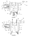
Figure 1 represents a molecular beam epitaxy system comprising a second trap means according to a first embodiment of the invention; -
Figure 2 represents a molecular beam epitaxy system comprising a second trap means according to a second embodiment of the invention; -
Figure 3 represents the evolution of gaseous precursor partial pressure in function of time, with and without second trap means; -
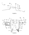
Figure 4 represents a molecular beam epitaxy system comprising a second trap means according to a third embodiment of the invention. -
Figure 1 represents a molecular beam epitaxy system comprising a second trap means according to a first embodiment of the invention. - The
figures 1, 2 and4 represent a molecular beam epitaxy system as an example of apparatus for depositing a thin film of material on a substrate. The invention is not limited to a molecular beam epitaxy system and can be applied to other apparatus for depositing a thin film of material on substrates, like CVD system for instance. - The molecular beam epitaxy system can produce wafers of semiconductor material comprising a substrate covered by a layer of semiconductor or insulating compound.
- The molecular beam epitaxy system of
figure 1 further comprises agrowth chamber 1 or vacuum chamber surrounding aprocess area 2. Thegrowth chamber 1 comprises alateral wall 3, a lower wall 4 and an upper wall 5. Each of these walls has an inner surface. Thegrowth chamber walls 3, 4, 5 form a unitary assembly which has the general shape of a cylinder. - The molecular beam epitaxy system comprises at least a
cryogenic panel 10. In the example offigure 1 , the molecular beam epitaxy system comprises onecryogenic panel 10 covering the inner surface of thelateral wall 3. We mean by "covering" the fact that thecryogenic panel 10 is disposed along this inner surface of thelateral wall 3 without contacting this last. - This
cryogenic panel 10 can be cooled with a cryogenic fluid like liquid nitrogen, glycol or other. Preferably, thecryogenic panel 10 has a cylindrical shape. - The molecular beam epitaxy system comprises a
sample holder 6 eventually surrounded by a secondarycryogenic panel 7 which has preferably a cylindrical shape. Thesample holder 6 is positioned at the top of thegrowth chamber 1 and is intended to support a substrate. - The substrate can be silicon, silicon carbide, sapphire, aluminium nitride, diamond, gallium nitride templates, for instance.
- The molecular beam epitaxy system comprises at least one
effusion cell 8 able to evaporate atoms or molecules of elements or compounds, and agas injector 9 able to inject a gaseous precursor into thegrowth chamber 1. Theeffusion cell 8 and thegas injector 9 are positioned at the bottom of thegrowth chamber 1. - The atoms or molecules of elements or compounds to be evaporated can be a metal of the group III and the element to be injected can be an element of the group V, for instance.
- Preferably, the molecular beam epitaxy system is used to obtain an epitaxial layer of GAN at the surface of a silicon substrate, the element of group III being gallium and the gaseous precursor comprising an element of the group V being ammonia (NH3).
- The molecular beam epitaxy system comprises first trap means 11 connected to the
growth chamber 1 and able to provide high vacuum capability. - The first trap means 11 can comprise a pumping
duct 30 having a wall. The pumpingduct 30 is connected to apumping device 21 by afirst end 12 and emerges into thegrowth chamber 1 by asecond end 13. - The
cryogenic panel 10 is provided with a hole 22 positioned in front of thesecond end 13 of the first trap means 11. - The first trap means 11 comprises a
cryogenic panel 17 covering the wall inner surface of the pumpingduct 30. Thecryogenic panel 17 is cooled with a cryogenic fluid like liquid nitrogen or glycol, for example. - We mean by "covering" the fact that the
cryogenic panel 17 is disposed along the wall inner surface of the pumpingduct 30 without contacting this last. - The
pumping device 21 can comprise a high vacuum pump associated with a low vacuum pump (not represented). It comprises switch means enabling to switch between the high vacuum pump and the low vacuum pump. - At high pressure, low vacuum pump which is more efficient, is used. When the pressure is sufficiently low, the high vacuum pump is used. Low vacuum pump can be a root pump and the high vacuum pump can be a turbomolecular pump, for example.
- During the growth process, the first trap means 11 is able to pump the gaseous elements which are not pumped by the
cryogenic panel 10. Thecryogenic panel 10 associated with the first trap means 11 can provide high vacuum capability. The first trap means 11 have a fixed pumping capacity S1 (I/s) and can provide a pumping flow Q1 (Pa.l.s-1). Q1 is defined by the relation: Q1 = P x S1 with P the gaseous precursor partial pressure (Pascal). - First trap means 11 comprise closing means 19 able to isolate the volume of the pumping
duct 30 of the first trap means 11 from the volume of thevacuum chamber 1 during the regeneration process. The pumpingduct 30 is like an intermediate volume. - These closing means 19 can consist in a valve disposed between the first trap means 11 and the
growth chamber 1. - When too much frozen precursor is accumulated on the
cryogenic panels 10 of thegrowth chamber 1, it is necessary to regenerate thesecryogenic panels 10. - The regeneration process of the
cryogenic panels 10 comprises a first step a) of evacuation of the precursor out of the vacuum chamber. During this step a), at least acryogenic panel 10 located inside thevacuum chamber 1 is heated, producing the desorption of the gaseous precursor initially adsorbed on thiscryogenic panel 10. - The
cryogenic panel 10 is heat-up freely (by stopping the cryogenic fluid flow for example) or with heating source fixed around the wall of thegrowth chamber 1. - When the flow of cryogenic fluid is stopped in this
cryogenic panel 10, the temperature of thecryogenic panel 10 increases and gaseous precursor desorbs from its surface. -
Figure 3 represents the evolution of gaseous precursor partial pressure in function of time. -
Abscise 31 represents the time andordinate 32 represents the pressure. The curve referred 49 represents the evolution of the pressure in function of time, for a prior art apparatus. - The curve referred 49 shows that the pressure in the
growth chamber 1 increases exponentially to a maximum ofpressure 52. - During this step a), a part of the desorbed gaseous precursor is trapped by the first trap means 11. In particular, a portion of this part of the desorbed gaseous precursor is trapped on the
cryogenic panel 17 of the first trap means 11. An other portion of this part of the desorbed gaseous precursor is pumped by thepumping device 21. - The principle is to transfer the majority of the gaseous precursor from the
cryogenic panels 10 of thegrowth chamber 1 toward thecryogenic panel 17 of the first trap means 11 which can be isolated later for its regeneration. - In the examples of
figures 1 to 3 , only thecryogenic panel 10 is regenerated. - The
cryogenic panel 17 of the first trap means 11 is cooled, and the closing means 19 are opened in order to permit the transfer of the gaseous precursor desorbing from thecryogenic panel 10 toward thecryogenic panel 17 of the first trap means 11. Thepumping device 21 of the first trap means 11 is working during this operation. - The pumping or trapping capacity S1 of the first trap means 11 is the combination of the pumping capacity of the pumping device 21 (actives pumps) and the pumping capacity of the
cryogenic panel 17 of the first trap means 11. - The regeneration process can be declined in various procedures.
- If the
growth chamber 1 comprises several cryogenic panels, the cryogenic panels can be heated simultaneously or sequentially. - For example, during the step a), the cryogenic panels can be heated sequentially.
- It permits to separate the different flows of evaporated gaseous precursor from the different cryogenic panels, and so to avoid the addition of pressure due to the addition of these flows.
- The regeneration process of the
cryogenic panels 10 comprises an operation of regeneration b) of thecryogenic panel 17 of the first trap means 11. During this step b) the first trap means 11 are isolated from thevacuum chamber 1 by the closing means 19. - The
cryogenic panel 17 of the first trap means 11 is heated, producing the desorption of the trapped gaseous precursor from thecryogenic panel 17. The desorbed gaseous precursor is pumped by thepumping device 21 to reach a high vacuum. - The pressure of gaseous precursor during the regeneration process of the
cryogenic panels 10 depends of three parameters: - The flow of gaseous precursor which depends of the remaining amount of gaseous precursor, the surface covered by frozen gaseous precursor and the temperature of this surface;
- The pumping capacity S of the pumps used to pump the gaseous precursor. It must be noticed that cryogenic panels which are cooled must be considered as pumps too, as they are collecting gaseous precursor;
- The conductance of the path between the gaseous precursor source (heated cryogenic panels) and the pumps (active pump or cold cryogenic panel).
- High gaseous precursor flow, coming from big amount of remaining gaseous precursor, large surface, high temperature, low pumping capacity and low conductance, induces a high pressure.
- To reduce this pressure, the regeneration process of the
cryogenic panels 10 comprises a complementary trapping operation of an other part of the gaseous precursor released by thecryogenic panels 10. - The molecular beam epitaxy system comprises second trap means 18 having a variable pumping capacity S2 able to be regulated in function of the gaseous precursor partial pressure. The first and second trap means provide a total pumping capacity S = S1 + S2, sufficient to maintain the gaseous precursor partial pressure in the
vacuum chamber 1 under a determined pressure PL. - The second trap means 18 permit to maintain the gas pressure in the
growth chamber 1 under a desired or determined pressure PL when the pumping capacity S1 of the first trap means 11 is not sufficient. The aim of the second trap means 18 is to not go over a given limit of pressure in order to avoid to nitride hot components (effusion cell for example) or hot materials. Advantageously, the pressure is linear. - This determined pressure PL can correspond to a limit wherein the aluminum or gallium source is not oxidized, for example.
- For example, when using gaseous ammonia as gaseous precursor, the determined pressure PL can be between 10-2 and 10-1 Pascal.
- This determined pressure PL can correspond to a limit wherein the molecular beam epitaxy system is secured (about 2.105 Pascal).
- For a given pumping capacity S, the pressure is proportional to the ammonia flow. Consequently, lowering the regulated pressure induce a lower flow of desorbing ammonia. For a given amount of ammonia, it leads to a longer regeneration time. So the closer the regulated pressure to the determined pressure is, the shorter the regeneration time is.
- The second trap means 18 comprise at least a regulating cryogenic element positioned inside the
vacuum chamber 1. The regulating cryogenic element is able to be supplied by a cryogenic fluid to be cooled. The cryogenic fluid can be liquid nitrogen or glycol, for example. - In a possible embodiment, represented in
figure 1 , the regulating cryogenic element consists in an additionalcryogenic element 55. Preferably, this additionalcryogenic element 55 is a small cryogenic panel. - This additional
cryogenic element 55 acts as a temporary pump to trap the extra ammonia coming from the big cryogenic panels. Controlling the temperature of a smaller cryogenic panel is easier thanks to its small inertia compared to a large one. - This additional
cryogenic element 55 is controlled by acontrol unit 48, and is preferably positioned at the lower part of thegrowth chamber 1. - This position has some interests to trap the ammonia accumulated on the lower part of the
cryogenic panel 10 during its regeneration. - Alternatively, the additional
cryogenic element 55 can be positioned at an other part of thegrowth chamber 1. - When the regeneration of the
cryogenic panel 10 is finished, ammonia is accumulated on the additionalcryogenic element 55 and can be evacuate later, for instance. - Cryogenic panels have a huge pumping capacity of ammonia. A surface at liquid nitrogen temperature (78 K) has a pumping capacity of 100 000 l/s per square meter for ammonia, which is huge, compared to the pumping capacity of a turbomolecular pump or cryogenic pump having a pumping speed of 5000 l/s.
- Alternatively, the regulating cryogenic element consists in the secondary
cryogenic panel 7. - Alternatively, as illustrated in
figure 4 , the regulating cryogenic element can consist in at least one of thecryogenic panels 10 positioned inside the vacuum chamber 1 (lateral or upper or lower cryogenic panel, for instance). - In the
figure 4 , the regulating cryogenic element consists in thecryogenic panel 10 covering the inner surface of thelateral wall 3. - Alternatively, the regulating cryogenic element can consist in a cryogenic panel covering the lateral, the upper and the lower part of the wall of the
vacuum chamber 1. - The second trap means 18 comprise a
pressure gauge 46 able to measure the gaseous precursor partial pressure inside thevacuum chamber 1, generating a measured pressure PM. - The second trap means 18 comprises a
valve 47 able to adjust the cryogenic fluid flow into the regulating cryogenic element. Thisvalve 47 can be an electronic valve. - The
control unit 48 of the second trap means 18 receives the measured pressure PM and compares this one to the determined pressure PL. - If the measured pressure PM is different from the determined pressure PL, the
control unit 48 is able to command thevalve 47 for adjusting the cryogenic fluid flow in the regulating cryogenic element, such that the measured pressure PM reaches the determined pressure PL. - For example, during regeneration of one or more
cryogenic panels 10 of thegrowth chamber 1, if the measured pressure PM of gaseous ammonia is superior to the determined pressure PL, thevalve 47 is opened in order to increase the flow of cryogenic fluid entering in the regulating cryogenic element. Thus the temperature of the regulating cryogenic element decreases. It adsorbs more gaseous ammonia such that the measured pressure PM decreases to reach the determined pressure PL. - The measured pressure PM can be around the determined pressure PL and not exactly equal to this last.
- If the measured pressure PM is inferior to the determined pressure PL, the
valve 47 is closed in order to decrease the flow of cryogenic fluid entering in the regulating cryogenic element. Thus the temperature of the regulating cryogenic element increases. It adsorbs less gaseous ammonia such that the measured pressure PM increases to reach the determined pressure PL. - In an other possible embodiment, the pressure regulation can be done by adjusting the flow of cryogenic fluid in several regulating cryogenic elements.
- This control can be done automatically using the
control unit 48 which can be closed loop system with a PID regulator or switch on/switch off hysteresis controller. Alternatively, relays switching electrical power can be used. - In
figure 3 , the curves referred 50 and 53 represent the evolution of the pressure in function of time during the regeneration process while the second trap means 18 control the regulating cryogenic element. Thiscurve 50 is given for a first example of determined pressure PL. - This
curve 50 shows that the pressure reaches a maximum ofpressure 51 which is inferior to the maximum ofpressure 52 reached without second trap means 18. - Others determined pressures PL are possible.
Curve 53 is given for a second example of determined pressure PL. This second determined pressure PL is lower than the first one, leading to a longer regeneration time. -
Curve 53 shows that the pressure in thegrowth chamber 1 reaches a second maximum ofpressure 54, lower than the first maximum ofpressure 51. - Gaseous precursor desorbing from one or more
cryogenic panels 10 is associated to a desorbing gaseous precursor flow Qdes. The first and second trap means 11, 18 provide a pumping flow Qpump, with Qpump = Qpump1 + Qpump2. Qpump1 is associated with the first trap means 11 and Qpump2 is associated with the second trap means 18. The invention enables to control the global flow Q = Qdes - Qpump, with Q = P x S (P being the pressure and S the pumping capacity). - Thus, the invention enables to limit the pressure of gaseous precursor, ammonia for instance, in a vacuum or growth chamber of an apparatus for depositing a thin film of material on a substrate, during the regeneration of the cryogenic panels of the growth chamber. For instance, components like effusion cell can be kept in a hot status without risk to damage them.
Claims (12)
- Apparatus for depositing a thin film of material on a substrate comprising:- a vacuum chamber (1),- a sample holder (6) disposed inside said vacuum chamber (1), said sample holder (6) being able to support said substrate,- a gas injector (9) able to inject a gaseous precursor into the vacuum chamber (1), a part of said gaseous precursor being able to react at the surface of the substrate,- at least one cryogenic panel (10) positioned inside the vacuum chamber (1) and able to adsorb a part of said gaseous precursor which has not reacted at the surface of the substrate, and to release said adsorbed gaseous precursor,- first trap means (11) connected to said vacuum chamber (1) and able to trap a part of said gaseous precursor released by said cryogenic panel (10), said first trap means (11) having a fixed pumping capacity S1, characterised in that it comprises:- second trap means (18) able to trap an other part of said gaseous precursor released by said cryogenic panel (10) and having a variable pumping capacity S2 able to be regulated in function of the gaseous precursor partial pressure,- said first and second trap means providing a total pumping capacity S = S1 + S2 sufficient to maintain the gaseous precursor partial pressure in the vacuum chamber (1) under a determined pressure PL.
- Apparatus for depositing a thin film of material on a substrate according to claim 1, characterised in that said second trap means (18) comprise:- at least a regulating cryogenic element positioned inside said vacuum chamber (1), said regulating cryogenic element being able to be supplied by a cryogenic fluid,- a pressure gauge (46) able to measure the gaseous precursor partial pressure inside the vacuum chamber (1), generating a measured pressure PM,- a valve (47) able to adjust the cryogenic fluid flow into said regulating cryogenic element, and- a control unit (48) able to receive said measured pressure PM and compare this one to the determined pressure PL, if the measured pressure PM is different from the determined pressure PL, said control unit (48) is able to command said valve (47) for adjusting the cryogenic fluid flow in said regulating cryogenic element, such that the measured pressure PM reaches the determined pressure PL.
- Apparatus for depositing a thin film of material on a substrate according to claim 2, characterised in that said regulating cryogenic element is an additional cryogenic element (55).
- Apparatus for depositing a thin film of material on a substrate according to claim 2, characterised in that said regulating cryogenic element consists in said at least one cryogenic panel (10) positioned inside the vacuum chamber (1).
- Apparatus for depositing a thin film of material on a substrate according to claim 2, characterised in that, said sample holder (6) being surrounded by a secondary cryogenic panel (7), said regulating cryogenic element consists in said secondary cryogenic panel (7).
- Apparatus for depositing a thin film of material on a substrate according to any one of claims 1 to 5, characterised in that said first trap means (11) comprise a pumping duct (30) having a wall, said pumping duct (30) being connected to a pumping device (21) by a first ends (12) and emerging into the growth chamber (1) by a second ends (13), and the wall inner surface of said pumping duct (30) being covered by a cryogenic panel (17).
- Apparatus for depositing a thin film of material on a substrate according to claim 6, characterised in that said first trap means (11) comprise closing means (19) able to isolate the volume of the pumping duct (30) of said first trap means (11) from the volume of the vacuum chamber (1).
- Apparatus for depositing a thin film of material on a substrate according to any one of claims 1 to 7, characterised in that it consists in a molecular beam epitaxy system for producing wafers of semiconductor material comprising a substrate, said vacuum chamber (1) being a growth chamber (1) including further a lateral wall (3) having an inner surface, a cryogenic panel (10) covering the inner surface of said lateral wall (3), said apparatus for depositing a thin film of material on a substrate comprising at least one effusion cell (8) able to evaporate atoms or molecules of elements or compounds, a part of said gaseous precursor being able to react with the evaporated atoms or molecules of elements or compounds on the surface of the substrate to form a layer of semiconductor or insulating compound.
- Regeneration process for cryogenic panels of an apparatus for depositing a thin film of material on a substrate according to any one of claims 1 to 8, said regeneration process comprising further the successive steps of:a) evacuation of the precursor out of the vacuum chamber, said step a) including the operations of:- heating at least a cryogenic panel (10) located inside the vacuum chamber (1) producing the desorption of the gaseous precursor initially adsorbed on said cryogenic panel (10),- trapping a part of said desorbed gaseous precursor by first trap means (11) having a fixed pumping capacity S1, a portion of said part of the desorbed gaseous precursor being trapped on the cryogenic panel (17) of said first trap means (11),b) regeneration of the cryogenic panel (17) of said first trap means (11), said step b) including the operations of:- isolating said first trap means (11) from the vacuum chamber (1),- heating said cryogenic panel (17) of the first trap means (11) producing the desorption of the trapped gaseous precursor from the cryogenic panel (17), and- pumping said desorbed gaseous precursor by one ore more pumps to reach a high vacuum,characterised in that it comprises, during the step a):- a complementary trapping operation, by second trap means (18), of an other part of said gaseous precursor released by said cryogenic panel (10), said second trap means (18) having a variable pumping capacity S2 able to be regulated in function of the gaseous precursor partial pressure,- said trapping operations providing a total pumping capacity S = S1 + S2 sufficient to maintain the gaseous precursor partial pressure in the vacuum chamber (1) under a determined pressure PL.
- Regeneration process according to claim 9, characterised in that the complementary trapping operation comprises the steps of:- measuring the gaseous precursor pressure inside said vacuum chamber (1), generating a measured pressure PM,- comparing the measured pressure PM to the determined pressure PL, if the measured pressure PM is different from the determined pressure PL, the pumping capacity S2 of a regulating cryogenic element located inside said vacuum chamber (1) is adjusted, such that the measured pressure PM reaches the determined pressure PL.
- Regeneration process according to any one of claims 9 or 10, characterised in that, the pumping capacity S2 of said regulating cryogenic element is adjusted by varying the cryogenic fluid flow in said regulating cryogenic element.
- Regeneration process according to any one of claims 9 to 11, characterised in that the gaseous precursor is gaseous ammonia, the determined pressure PL being between 10-2 and 10-1 Pascal.
Priority Applications (11)
| Application Number | Priority Date | Filing Date | Title |
|---|---|---|---|
| ES09305569T ES2385460T3 (en) | 2009-06-18 | 2009-06-18 | Apparatus for depositing a thin film of material on a substrate and regeneration process for such an apparatus |
| DK09305569.7T DK2264224T3 (en) | 2009-06-18 | 2009-06-18 | Apparatus for applying a thin film of a material to a substrate and regeneration method for such apparatus |
| PL09305569T PL2264224T3 (en) | 2009-06-18 | 2009-06-18 | Apparatus for depositing a thin film of material on a substrate and regeneration process for such an apparatus |
| AT09305569T ATE556160T1 (en) | 2009-06-18 | 2009-06-18 | DEVICE FOR DEPOSING A THIN LAYER OF A MATERIAL ON A SUBSTRATE AND REGENERATION METHOD FOR SUCH A DEVICE |
| EP09305569A EP2264224B1 (en) | 2009-06-18 | 2009-06-18 | Apparatus for depositing a thin film of material on a substrate and regeneration process for such an apparatus |
| CN201080036143.8A CN102803579B (en) | 2009-06-18 | 2010-06-17 | Apparatus for depositing a thin film of material on a substrate and regeneration process for such an apparatus |
| US13/379,220 US8858713B2 (en) | 2009-06-18 | 2010-06-17 | Apparatus for depositing a thin film of material on a substrate and regeneration process for such an apparatus |
| KR1020117030410A KR20120039549A (en) | 2009-06-18 | 2010-06-17 | Apparatus for depositing a thin film of material on a substrate and regeneration process for such an apparatus |
| PCT/EP2010/058571 WO2010146130A1 (en) | 2009-06-18 | 2010-06-17 | Apparatus for depositing a thin film of material on a substrate and regeneration process for such an apparatus |
| JP2012515502A JP2012530372A (en) | 2009-06-18 | 2010-06-17 | Apparatus for depositing a thin film of material on a substrate and method for regenerating such an apparatus |
| SG2011093846A SG176908A1 (en) | 2009-06-18 | 2010-06-17 | Apparatus for depositing a thin film of material on a substrate and regeneration process for such an apparatus |
Applications Claiming Priority (1)
| Application Number | Priority Date | Filing Date | Title |
|---|---|---|---|
| EP09305569A EP2264224B1 (en) | 2009-06-18 | 2009-06-18 | Apparatus for depositing a thin film of material on a substrate and regeneration process for such an apparatus |
Publications (2)
| Publication Number | Publication Date |
|---|---|
| EP2264224A1 true EP2264224A1 (en) | 2010-12-22 |
| EP2264224B1 EP2264224B1 (en) | 2012-05-02 |
Family
ID=41319802
Family Applications (1)
| Application Number | Title | Priority Date | Filing Date |
|---|---|---|---|
| EP09305569A Active EP2264224B1 (en) | 2009-06-18 | 2009-06-18 | Apparatus for depositing a thin film of material on a substrate and regeneration process for such an apparatus |
Country Status (11)
| Country | Link |
|---|---|
| US (1) | US8858713B2 (en) |
| EP (1) | EP2264224B1 (en) |
| JP (1) | JP2012530372A (en) |
| KR (1) | KR20120039549A (en) |
| CN (1) | CN102803579B (en) |
| AT (1) | ATE556160T1 (en) |
| DK (1) | DK2264224T3 (en) |
| ES (1) | ES2385460T3 (en) |
| PL (1) | PL2264224T3 (en) |
| SG (1) | SG176908A1 (en) |
| WO (1) | WO2010146130A1 (en) |
Families Citing this family (4)
| Publication number | Priority date | Publication date | Assignee | Title |
|---|---|---|---|---|
| KR102052074B1 (en) | 2013-04-04 | 2019-12-05 | 삼성디스플레이 주식회사 | Deposition apparatus, method for forming thin film using the same and method for manufacturing organic light emitting display apparatus |
| DE102017106431A1 (en) | 2017-03-24 | 2018-09-27 | Aixtron Se | Apparatus and method for reducing the water partial pressure in an OVPD coating device |
| US11519095B2 (en) | 2019-04-22 | 2022-12-06 | Peng DU | MBE system with direct evaporation pump to cold panel |
| WO2021030336A1 (en) | 2019-08-12 | 2021-02-18 | Kurt J. Lesker Company | Ultra high purity conditions for atomic scale processing |
Citations (3)
| Publication number | Priority date | Publication date | Assignee | Title |
|---|---|---|---|---|
| JPS6130664A (en) * | 1984-07-18 | 1986-02-12 | Rohm Co Ltd | Method of vapor deposition |
| US20020005566A1 (en) * | 1999-09-01 | 2002-01-17 | Weber Eicke R. | Process for growing epitaxial gallium nitride and composite wafers |
| EP2060662A2 (en) * | 2007-11-16 | 2009-05-20 | Forschungsverbund Berlin E.V. | MBE device and method of its operation |
Family Cites Families (7)
| Publication number | Priority date | Publication date | Assignee | Title |
|---|---|---|---|---|
| JPH0788578B2 (en) * | 1991-07-10 | 1995-09-27 | 財団法人国際超電導産業技術研究センター | Method and apparatus for manufacturing oxide thin film |
| JPH069297A (en) * | 1991-12-09 | 1994-01-18 | Sumitomo Electric Ind Ltd | Film forming device |
| WO1994003931A1 (en) * | 1992-08-07 | 1994-02-17 | Asahi Kasei Kogyo Kabushiki Kaisha | Nitride based semiconductor device and manufacture thereof |
| JPH0897147A (en) * | 1994-09-29 | 1996-04-12 | Mitsubishi Electric Corp | Epitaxial crystal growth device |
| FR2840925B1 (en) * | 2002-06-18 | 2005-04-01 | Riber | VAPOR MATERIAL EVAPORATION CHAMBER WITH DIFFERENTIAL PUMPING |
| JP4397655B2 (en) * | 2003-08-28 | 2010-01-13 | キヤノンアネルバ株式会社 | Sputtering apparatus, electronic component manufacturing apparatus, and electronic component manufacturing method |
| EP2066415A2 (en) * | 2006-09-25 | 2009-06-10 | Veeco Instruments Inc. | Thermally isolated cryopanel for vacuum deposition sytems |
-
2009
- 2009-06-18 EP EP09305569A patent/EP2264224B1/en active Active
- 2009-06-18 AT AT09305569T patent/ATE556160T1/en active
- 2009-06-18 ES ES09305569T patent/ES2385460T3/en active Active
- 2009-06-18 PL PL09305569T patent/PL2264224T3/en unknown
- 2009-06-18 DK DK09305569.7T patent/DK2264224T3/en active
-
2010
- 2010-06-17 US US13/379,220 patent/US8858713B2/en active Active
- 2010-06-17 KR KR1020117030410A patent/KR20120039549A/en not_active Application Discontinuation
- 2010-06-17 SG SG2011093846A patent/SG176908A1/en unknown
- 2010-06-17 JP JP2012515502A patent/JP2012530372A/en active Pending
- 2010-06-17 WO PCT/EP2010/058571 patent/WO2010146130A1/en active Application Filing
- 2010-06-17 CN CN201080036143.8A patent/CN102803579B/en active Active
Patent Citations (3)
| Publication number | Priority date | Publication date | Assignee | Title |
|---|---|---|---|---|
| JPS6130664A (en) * | 1984-07-18 | 1986-02-12 | Rohm Co Ltd | Method of vapor deposition |
| US20020005566A1 (en) * | 1999-09-01 | 2002-01-17 | Weber Eicke R. | Process for growing epitaxial gallium nitride and composite wafers |
| EP2060662A2 (en) * | 2007-11-16 | 2009-05-20 | Forschungsverbund Berlin E.V. | MBE device and method of its operation |
Also Published As
| Publication number | Publication date |
|---|---|
| SG176908A1 (en) | 2012-01-30 |
| US20120097102A1 (en) | 2012-04-26 |
| WO2010146130A1 (en) | 2010-12-23 |
| KR20120039549A (en) | 2012-04-25 |
| EP2264224B1 (en) | 2012-05-02 |
| ATE556160T1 (en) | 2012-05-15 |
| ES2385460T3 (en) | 2012-07-25 |
| US8858713B2 (en) | 2014-10-14 |
| CN102803579B (en) | 2015-04-22 |
| CN102803579A (en) | 2012-11-28 |
| JP2012530372A (en) | 2012-11-29 |
| PL2264224T3 (en) | 2012-09-28 |
| DK2264224T3 (en) | 2012-07-23 |
Similar Documents
| Publication | Publication Date | Title |
|---|---|---|
| US9938620B2 (en) | Gas supply mechanism, gas supplying method, film forming apparatus and film forming method using the same | |
| CN101365823B (en) | Film forming apparatus and film forming method | |
| US8858713B2 (en) | Apparatus for depositing a thin film of material on a substrate and regeneration process for such an apparatus | |
| JP5645718B2 (en) | Heat treatment equipment | |
| KR101799156B1 (en) | Source gas supply apparatus and film forming apparatus | |
| JP2011023706A5 (en) | ||
| WO2014007028A1 (en) | Film forming method and film forming device | |
| US6107198A (en) | Ammonium chloride vaporizer cold trap | |
| JP4074574B2 (en) | Organic vapor deposition equipment | |
| US20170130331A1 (en) | Method for mocvd gas showerhead pretreatment | |
| JP4359965B2 (en) | Deposition equipment | |
| JP2004047887A (en) | Sheet-fed cvd device | |
| EP2251451B1 (en) | Raw material supplying device | |
| JP7382893B2 (en) | Raw material supply equipment and film forming equipment | |
| US20200071827A1 (en) | Precursor Delivery System | |
| JP2006501639A (en) | Dual chamber integrated phase separator for ultra-high vacuum system This application is a PCT international application on July 29, 2003 in the name of Becoins Instruments Inc. It has been filed. | |
| US20180045697A1 (en) | Thermal desorption system and method of analyzing a substrate using the same | |
| EP2264225B1 (en) | Molecular beam epitaxy apparatus for producing wafers of semiconductor material | |
| KR200294169Y1 (en) | A heating device for manufacturing the wafer | |
| KR101375616B1 (en) | Bubbler for high temperature chemical vapor deposition | |
| JP2012160585A (en) | Raw material supply device and film forming apparatus | |
| US8900991B2 (en) | Film forming method and storage medium | |
| KR20230091780A (en) | Systems and methods for controlling moisture in semiconductor processing systems | |
| JP2014033143A (en) | Deposition method and deposition apparatus of compound semiconductor film | |
| JP2009088305A (en) | Method of manufacturing semiconductor device |
Legal Events
| Date | Code | Title | Description |
|---|---|---|---|
| PUAI | Public reference made under article 153(3) epc to a published international application that has entered the european phase |
Free format text: ORIGINAL CODE: 0009012 |
|
| AK | Designated contracting states |
Kind code of ref document: A1 Designated state(s): AT BE BG CH CY CZ DE DK EE ES FI FR GB GR HR HU IE IS IT LI LT LU LV MC MK MT NL NO PL PT RO SE SI SK TR |
|
| 17P | Request for examination filed |
Effective date: 20110503 |
|
| 17Q | First examination report despatched |
Effective date: 20110808 |
|
| REG | Reference to a national code |
Ref country code: DE Ref legal event code: R079 Ref document number: 602009006749 Country of ref document: DE Free format text: PREVIOUS MAIN CLASS: C30B0023020000 Ipc: C30B0029400000 |
|
| GRAP | Despatch of communication of intention to grant a patent |
Free format text: ORIGINAL CODE: EPIDOSNIGR1 |
|
| RIC1 | Information provided on ipc code assigned before grant |
Ipc: C30B 29/40 20060101AFI20111028BHEP |
|
| GRAS | Grant fee paid |
Free format text: ORIGINAL CODE: EPIDOSNIGR3 |
|
| GRAA | (expected) grant |
Free format text: ORIGINAL CODE: 0009210 |
|
| AK | Designated contracting states |
Kind code of ref document: B1 Designated state(s): AT BE BG CH CY CZ DE DK EE ES FI FR GB GR HR HU IE IS IT LI LT LU LV MC MK MT NL NO PL PT RO SE SI SK TR |
|
| REG | Reference to a national code |
Ref country code: GB Ref legal event code: FG4D |
|
| REG | Reference to a national code |
Ref country code: AT Ref legal event code: REF Ref document number: 556160 Country of ref document: AT Kind code of ref document: T Effective date: 20120515 Ref country code: CH Ref legal event code: EP |
|
| REG | Reference to a national code |
Ref country code: IE Ref legal event code: FG4D |
|
| REG | Reference to a national code |
Ref country code: CH Ref legal event code: NV Representative=s name: KIRKER & CIE S.A. |
|
| REG | Reference to a national code |
Ref country code: NL Ref legal event code: T3 |
|
| REG | Reference to a national code |
Ref country code: DE Ref legal event code: R096 Ref document number: 602009006749 Country of ref document: DE Effective date: 20120705 |
|
| REG | Reference to a national code |
Ref country code: DK Ref legal event code: T3 |
|
| REG | Reference to a national code |
Ref country code: SE Ref legal event code: TRGR |
|
| REG | Reference to a national code |
Ref country code: ES Ref legal event code: FG2A Ref document number: 2385460 Country of ref document: ES Kind code of ref document: T3 Effective date: 20120725 |
|
| REG | Reference to a national code |
Ref country code: NO Ref legal event code: T2 Effective date: 20120502 |
|
| REG | Reference to a national code |
Ref country code: PL Ref legal event code: T3 |
|
| REG | Reference to a national code |
Ref country code: LT Ref legal event code: MG4D Effective date: 20120502 |
|
| PG25 | Lapsed in a contracting state [announced via postgrant information from national office to epo] |
Ref country code: CY Free format text: LAPSE BECAUSE OF FAILURE TO SUBMIT A TRANSLATION OF THE DESCRIPTION OR TO PAY THE FEE WITHIN THE PRESCRIBED TIME-LIMIT Effective date: 20120502 Ref country code: IS Free format text: LAPSE BECAUSE OF FAILURE TO SUBMIT A TRANSLATION OF THE DESCRIPTION OR TO PAY THE FEE WITHIN THE PRESCRIBED TIME-LIMIT Effective date: 20120902 Ref country code: LT Free format text: LAPSE BECAUSE OF FAILURE TO SUBMIT A TRANSLATION OF THE DESCRIPTION OR TO PAY THE FEE WITHIN THE PRESCRIBED TIME-LIMIT Effective date: 20120502 |
|
| REG | Reference to a national code |
Ref country code: HU Ref legal event code: AG4A Ref document number: E014244 Country of ref document: HU |
|
| PG25 | Lapsed in a contracting state [announced via postgrant information from national office to epo] |
Ref country code: LV Free format text: LAPSE BECAUSE OF FAILURE TO SUBMIT A TRANSLATION OF THE DESCRIPTION OR TO PAY THE FEE WITHIN THE PRESCRIBED TIME-LIMIT Effective date: 20120502 Ref country code: GR Free format text: LAPSE BECAUSE OF FAILURE TO SUBMIT A TRANSLATION OF THE DESCRIPTION OR TO PAY THE FEE WITHIN THE PRESCRIBED TIME-LIMIT Effective date: 20120803 Ref country code: SI Free format text: LAPSE BECAUSE OF FAILURE TO SUBMIT A TRANSLATION OF THE DESCRIPTION OR TO PAY THE FEE WITHIN THE PRESCRIBED TIME-LIMIT Effective date: 20120502 Ref country code: HR Free format text: LAPSE BECAUSE OF FAILURE TO SUBMIT A TRANSLATION OF THE DESCRIPTION OR TO PAY THE FEE WITHIN THE PRESCRIBED TIME-LIMIT Effective date: 20120502 Ref country code: PT Free format text: LAPSE BECAUSE OF FAILURE TO SUBMIT A TRANSLATION OF THE DESCRIPTION OR TO PAY THE FEE WITHIN THE PRESCRIBED TIME-LIMIT Effective date: 20120903 |
|
| PG25 | Lapsed in a contracting state [announced via postgrant information from national office to epo] |
Ref country code: EE Free format text: LAPSE BECAUSE OF FAILURE TO SUBMIT A TRANSLATION OF THE DESCRIPTION OR TO PAY THE FEE WITHIN THE PRESCRIBED TIME-LIMIT Effective date: 20120502 Ref country code: RO Free format text: LAPSE BECAUSE OF FAILURE TO SUBMIT A TRANSLATION OF THE DESCRIPTION OR TO PAY THE FEE WITHIN THE PRESCRIBED TIME-LIMIT Effective date: 20120502 Ref country code: SK Free format text: LAPSE BECAUSE OF FAILURE TO SUBMIT A TRANSLATION OF THE DESCRIPTION OR TO PAY THE FEE WITHIN THE PRESCRIBED TIME-LIMIT Effective date: 20120502 Ref country code: MC Free format text: LAPSE BECAUSE OF NON-PAYMENT OF DUE FEES Effective date: 20120630 |
|
| PG25 | Lapsed in a contracting state [announced via postgrant information from national office to epo] |
Ref country code: MK Free format text: LAPSE BECAUSE OF FAILURE TO SUBMIT A TRANSLATION OF THE DESCRIPTION OR TO PAY THE FEE WITHIN THE PRESCRIBED TIME-LIMIT Effective date: 20120502 |
|
| PLBE | No opposition filed within time limit |
Free format text: ORIGINAL CODE: 0009261 |
|
| STAA | Information on the status of an ep patent application or granted ep patent |
Free format text: STATUS: NO OPPOSITION FILED WITHIN TIME LIMIT |
|
| 26N | No opposition filed |
Effective date: 20130205 |
|
| REG | Reference to a national code |
Ref country code: DE Ref legal event code: R097 Ref document number: 602009006749 Country of ref document: DE Effective date: 20130205 |
|
| PG25 | Lapsed in a contracting state [announced via postgrant information from national office to epo] |
Ref country code: BG Free format text: LAPSE BECAUSE OF FAILURE TO SUBMIT A TRANSLATION OF THE DESCRIPTION OR TO PAY THE FEE WITHIN THE PRESCRIBED TIME-LIMIT Effective date: 20120802 Ref country code: MT Free format text: LAPSE BECAUSE OF FAILURE TO SUBMIT A TRANSLATION OF THE DESCRIPTION OR TO PAY THE FEE WITHIN THE PRESCRIBED TIME-LIMIT Effective date: 20120502 |
|
| PGFP | Annual fee paid to national office [announced via postgrant information from national office to epo] |
Ref country code: DK Payment date: 20140307 Year of fee payment: 6 Ref country code: IE Payment date: 20140307 Year of fee payment: 6 Ref country code: SE Payment date: 20140311 Year of fee payment: 6 |
|
| PG25 | Lapsed in a contracting state [announced via postgrant information from national office to epo] |
Ref country code: LU Free format text: LAPSE BECAUSE OF NON-PAYMENT OF DUE FEES Effective date: 20120618 |
|
| PGFP | Annual fee paid to national office [announced via postgrant information from national office to epo] |
Ref country code: BE Payment date: 20140307 Year of fee payment: 6 |
|
| PGFP | Annual fee paid to national office [announced via postgrant information from national office to epo] |
Ref country code: AT Payment date: 20140414 Year of fee payment: 6 Ref country code: IT Payment date: 20140626 Year of fee payment: 6 Ref country code: CZ Payment date: 20140612 Year of fee payment: 6 Ref country code: NL Payment date: 20140618 Year of fee payment: 6 Ref country code: ES Payment date: 20140416 Year of fee payment: 6 Ref country code: NO Payment date: 20140612 Year of fee payment: 6 Ref country code: TR Payment date: 20140528 Year of fee payment: 6 |
|
| PGFP | Annual fee paid to national office [announced via postgrant information from national office to epo] |
Ref country code: PL Payment date: 20140523 Year of fee payment: 6 Ref country code: HU Payment date: 20140618 Year of fee payment: 6 |
|
| PGFP | Annual fee paid to national office [announced via postgrant information from national office to epo] |
Ref country code: CH Payment date: 20150508 Year of fee payment: 7 |
|
| REG | Reference to a national code |
Ref country code: NO Ref legal event code: MMEP Ref country code: DK Ref legal event code: EBP Effective date: 20150630 |
|
| PG25 | Lapsed in a contracting state [announced via postgrant information from national office to epo] |
Ref country code: IT Free format text: LAPSE BECAUSE OF NON-PAYMENT OF DUE FEES Effective date: 20150618 |
|
| REG | Reference to a national code |
Ref country code: SE Ref legal event code: EUG |
|
| REG | Reference to a national code |
Ref country code: AT Ref legal event code: MM01 Ref document number: 556160 Country of ref document: AT Kind code of ref document: T Effective date: 20150618 |
|
| PG25 | Lapsed in a contracting state [announced via postgrant information from national office to epo] |
Ref country code: CZ Free format text: LAPSE BECAUSE OF NON-PAYMENT OF DUE FEES Effective date: 20150618 Ref country code: SE Free format text: LAPSE BECAUSE OF NON-PAYMENT OF DUE FEES Effective date: 20150619 |
|
| REG | Reference to a national code |
Ref country code: NL Ref legal event code: MM Effective date: 20150701 |
|
| REG | Reference to a national code |
Ref country code: FR Ref legal event code: PLFP Year of fee payment: 8 |
|
| REG | Reference to a national code |
Ref country code: IE Ref legal event code: MM4A |
|
| PG25 | Lapsed in a contracting state [announced via postgrant information from national office to epo] |
Ref country code: NL Free format text: LAPSE BECAUSE OF NON-PAYMENT OF DUE FEES Effective date: 20150701 Ref country code: IE Free format text: LAPSE BECAUSE OF NON-PAYMENT OF DUE FEES Effective date: 20150618 Ref country code: NO Free format text: LAPSE BECAUSE OF NON-PAYMENT OF DUE FEES Effective date: 20150630 |
|
| PG25 | Lapsed in a contracting state [announced via postgrant information from national office to epo] |
Ref country code: HU Free format text: LAPSE BECAUSE OF NON-PAYMENT OF DUE FEES Effective date: 20150619 Ref country code: AT Free format text: LAPSE BECAUSE OF NON-PAYMENT OF DUE FEES Effective date: 20150618 |
|
| PG25 | Lapsed in a contracting state [announced via postgrant information from national office to epo] |
Ref country code: DK Free format text: LAPSE BECAUSE OF NON-PAYMENT OF DUE FEES Effective date: 20150630 |
|
| PG25 | Lapsed in a contracting state [announced via postgrant information from national office to epo] |
Ref country code: PL Free format text: LAPSE BECAUSE OF NON-PAYMENT OF DUE FEES Effective date: 20150618 |
|
| REG | Reference to a national code |
Ref country code: CH Ref legal event code: PL |
|
| REG | Reference to a national code |
Ref country code: ES Ref legal event code: FD2A Effective date: 20170224 |
|
| REG | Reference to a national code |
Ref country code: FR Ref legal event code: PLFP Year of fee payment: 9 |
|
| PG25 | Lapsed in a contracting state [announced via postgrant information from national office to epo] |
Ref country code: CH Free format text: LAPSE BECAUSE OF NON-PAYMENT OF DUE FEES Effective date: 20160630 Ref country code: LI Free format text: LAPSE BECAUSE OF NON-PAYMENT OF DUE FEES Effective date: 20160630 |
|
| PG25 | Lapsed in a contracting state [announced via postgrant information from national office to epo] |
Ref country code: ES Free format text: LAPSE BECAUSE OF NON-PAYMENT OF DUE FEES Effective date: 20150619 |
|
| PG25 | Lapsed in a contracting state [announced via postgrant information from national office to epo] |
Ref country code: BE Free format text: LAPSE BECAUSE OF NON-PAYMENT OF DUE FEES Effective date: 20150630 |
|
| PG25 | Lapsed in a contracting state [announced via postgrant information from national office to epo] |
Ref country code: TR Free format text: LAPSE BECAUSE OF NON-PAYMENT OF DUE FEES Effective date: 20150618 |
|
| REG | Reference to a national code |
Ref country code: FR Ref legal event code: PLFP Year of fee payment: 10 |
|
| PGFP | Annual fee paid to national office [announced via postgrant information from national office to epo] |
Ref country code: FR Payment date: 20230307 Year of fee payment: 15 Ref country code: FI Payment date: 20230302 Year of fee payment: 15 |
|
| PGFP | Annual fee paid to national office [announced via postgrant information from national office to epo] |
Ref country code: DE Payment date: 20230302 Year of fee payment: 15 |
|
| PGFP | Annual fee paid to national office [announced via postgrant information from national office to epo] |
Ref country code: GB Payment date: 20230405 Year of fee payment: 15 |
|
| PGFP | Annual fee paid to national office [announced via postgrant information from national office to epo] |
Ref country code: FI Payment date: 20240306 Year of fee payment: 16 |