EP2263944A1 - Installation for the processing of trays - Google Patents
Installation for the processing of trays Download PDFInfo
- Publication number
- EP2263944A1 EP2263944A1 EP09380120A EP09380120A EP2263944A1 EP 2263944 A1 EP2263944 A1 EP 2263944A1 EP 09380120 A EP09380120 A EP 09380120A EP 09380120 A EP09380120 A EP 09380120A EP 2263944 A1 EP2263944 A1 EP 2263944A1
- Authority
- EP
- European Patent Office
- Prior art keywords
- trays
- machine
- installation
- stack
- dirt
- Prior art date
- Legal status (The legal status is an assumption and is not a legal conclusion. Google has not performed a legal analysis and makes no representation as to the accuracy of the status listed.)
- Granted
Links
- 238000009434 installation Methods 0.000 title claims abstract description 22
- 230000003749 cleanliness Effects 0.000 claims abstract description 5
- 210000000078 claw Anatomy 0.000 claims description 6
- 230000004888 barrier function Effects 0.000 claims description 2
- 230000000694 effects Effects 0.000 claims description 2
- 230000005484 gravity Effects 0.000 claims description 2
- 238000000034 method Methods 0.000 description 4
- 238000004140 cleaning Methods 0.000 description 3
- 230000000295 complement effect Effects 0.000 description 2
- 239000007787 solid Substances 0.000 description 2
- 239000002699 waste material Substances 0.000 description 2
- 230000001143 conditioned effect Effects 0.000 description 1
- 238000000151 deposition Methods 0.000 description 1
- 238000001514 detection method Methods 0.000 description 1
- 239000003814 drug Substances 0.000 description 1
- 230000005611 electricity Effects 0.000 description 1
- 230000008030 elimination Effects 0.000 description 1
- 238000003379 elimination reaction Methods 0.000 description 1
- 238000005516 engineering process Methods 0.000 description 1
- 230000003068 static effect Effects 0.000 description 1
Images


Classifications
-
- B—PERFORMING OPERATIONS; TRANSPORTING
- B65—CONVEYING; PACKING; STORING; HANDLING THIN OR FILAMENTARY MATERIAL
- B65B—MACHINES, APPARATUS OR DEVICES FOR, OR METHODS OF, PACKAGING ARTICLES OR MATERIALS; UNPACKING
- B65B69/00—Unpacking of articles or materials, not otherwise provided for
-
- B—PERFORMING OPERATIONS; TRANSPORTING
- B65—CONVEYING; PACKING; STORING; HANDLING THIN OR FILAMENTARY MATERIAL
- B65G—TRANSPORT OR STORAGE DEVICES, e.g. CONVEYORS FOR LOADING OR TIPPING, SHOP CONVEYOR SYSTEMS OR PNEUMATIC TUBE CONVEYORS
- B65G47/00—Article or material-handling devices associated with conveyors; Methods employing such devices
- B65G47/22—Devices influencing the relative position or the attitude of articles during transit by conveyors
- B65G47/24—Devices influencing the relative position or the attitude of articles during transit by conveyors orientating the articles
- B65G47/248—Devices influencing the relative position or the attitude of articles during transit by conveyors orientating the articles by turning over or inverting them
- B65G47/252—Devices influencing the relative position or the attitude of articles during transit by conveyors orientating the articles by turning over or inverting them about an axis substantially perpendicular to the conveying direction
-
- G—PHYSICS
- G01—MEASURING; TESTING
- G01N—INVESTIGATING OR ANALYSING MATERIALS BY DETERMINING THEIR CHEMICAL OR PHYSICAL PROPERTIES
- G01N21/00—Investigating or analysing materials by the use of optical means, i.e. using sub-millimetre waves, infrared, visible or ultraviolet light
- G01N21/84—Systems specially adapted for particular applications
- G01N21/88—Investigating the presence of flaws or contamination
- G01N21/90—Investigating the presence of flaws or contamination in a container or its contents
- G01N21/9018—Dirt detection in containers
Definitions
- This invention refers to an installation that has been especially conceived for the processing of trays, of the kind used in product distribution lines of very diverse types, in which, once the content is extracted from them, they are returned to the distribution line to be used again.
- the purpose of the invention is to provide an installation by which the emptying of solids that may be in each tray is carried out in a totally automatic way prior to its subsequent use, including means to discriminate the entering trays, so that the trays that arrive wet or are dirtier than the established work levels are diverted to an area where the entering trays will be processed corresponding to their cleaning.
- the purpose of the invention is to provide an installation by which standards of cleanliness are guaranteed for the trays that are delivered to the warehouse.
- the invention has been especially conceived to be applied in the pharmaceutical sector, but obviously it can be applicable in other sectors in which similar features are required.
- distribution lines are used in factories in which the products, such as boxes of medicine and similar, are placed in trays, appropriately identified by means of bar codes or any other technology, so that by the conveyor belts, roller chains and similar, and the corresponding sensors and readers, the products are classified and distributed, according to the logistics of each case.
- the used trays are stacked and transported to a tray processing line, in which a separating machine is set up that puts the trays on a conveyor belt of the same type as used in the overturning machine, which hooks onto the trays, either lengthwise or crosswise, and turns them over a discard bin, in order to then return them to their initial position on the transport line.
- a separating machine is set up that puts the trays on a conveyor belt of the same type as used in the overturning machine, which hooks onto the trays, either lengthwise or crosswise, and turns them over a discard bin, in order to then return them to their initial position on the transport line.
- the tray processing installation that the invention proposes solves in a fully satisfactory way the aforementioned problem expressed in the different aspects, providing a high-quality cleaning system, totally automated, and with noticeable less work time.
- the invention is comprised by a roller line, in which four stages are set up: a first stage of separating the trays, a second stage of overturning and emptying them, a third stage of inspecting for dirt and discrimination, and a fourth stage of stacking in uniform stacks.
- a lifting machine is connected which is in charge of raising the stack of trays to the level of the conveyor rollers where this stack is transported to a separator, which, by means of some claws driven hydraulically and vertically moveable, allow separating the lower tray from the stack by raising said stack; this tray will advance through the roller line to an overturning machine, in which a series of slanted conveyor belts and rotating supports receive and overturn the trays; the tray is overturned by the simple effect of gravity, dumping its contents into a waste collection bin, proceeding then and in the same manner to being overturned again to adopt its initial position.
- the empty tray is taken, on the aforementioned roller line to a machine that inspects for dirt by artificial vision, in which is attached a camera connected to hardware with programmed software which detects the possible adhered dirt as well as moisture, so that at the outlet of this machine the roller line diverges into two branches, one towards the belts corresponding to the trays that did not pass the required standards of cleanliness and a main branch that leads to a stacking machine, with a structure similar to the separating machine, but with the opposite function.
- a diverter is set up which sends each stack of trays towards different roller chains that take these stacks to the different warehouses.
- the machine In order to avoid collisions in raising and lowering the stacks, the machine includes two photoelectric barriers (10-10').
- the roller line (1) takes the stack to the separating machine (11), that shown in Figure 3 , comprised of a column in whose middle area there is a section of rollers (14) continuing the roller line (1) next to which there are two sensors (32) to control the position of the stack at the time of entering the machine.
- This column incorporates some pneumatic claws (15) that are closed on the sides of the tray, holding it, and consequently the rest of the trays are stacked into it above, so that to separate it the machine is situated at the level of the second tray from the bottom, it closes on it, holding it, and proceeds to move said tray vertically, so that the lower tray is automatically separated, immediately connecting the drive of the roller section (14) that takes the separated tray alone towards the overturning machine (15), that shown in Figure 4 , which, through a pair of conveyor belts (16), open in their middle area and assisted on the ends by the respective overturning supports (17), allow in the first place to turn the tray over 180°, emptying its content into a bin (18), and subsequently returning to its initial position by means of the corresponding overturning.
- roller line section (1) with sufficient length as to permit accumulating several stacks of trays, including a photoelectric saturation sensor (12) and a pneumatic limit (13) that doses out and controls the entry of stacks to the separator.
- the outlet of the overturning machine is connected to a machine that inspects for dirt by artificial vision (19), in which there is a roller section (20), as a continuation of the roller line (1), a mechanism activated by means of a geared motor group (21).
- the machine includes a casing (22), open on both ends, in which a system of artificial vision is set up, which is comprised of a camera (23), a data processing unit, as well as LED projectors (24) that provide stable lighting conditions, so that through image-comparing software it detects the possible adhered dirt, as well as moisture, having provided that the flash of the camera (23) is done through a photoelectric sensor (25) that would detect the presence of the tray in the proper position to be photographed.
- roller line (1) diverges into two branches, a first branch (1') that takes the clean trays to a stacking machine (26), and a second branch (1") that by means of a diverter (27), that shown in the close up of Figure 6 , takes away the dirty trays for their proper cleaning.
- This diverter (27) is automatically activated upon detection of a dirty tray, so that through a photoelectric sensor (33) the drive of the rollers of the branch (1') stops and some belts (28) driven by a geared motor group (29) start up and move the tray to the branch (1"), a position that is detected through the corresponding photoelectric sensor (30), with this branch (1") including a photoelectric sensor (31) for the saturation of the line.
- the aforementioned stacking machine (26) will have a structure similar to that of the separator (11), with a column in the middle of which is a section of rollers (14'), two photoelectric sensors (32') for the control of the tray's position at the time it enters the machine, as well as some pneumatic claws (15') that close on the trays and move vertically, so that in this case, the claws (15) also move to the position immediately above the lower tray in order to proceed to open, depositing in that tray the set of trays that may have accumulated and stacked, in order to then move downwards a certain distance in order to hold the lower tray, and raise the entire stack allowing the entry of a new tray, and inserting in it the accumulated stack, repeating the process until reaching the programmed stack level.
- a second diverter in charge of taking the checked and stacked trays to the two warehouses with rollers (35) and (36), for which a photoelectric sensor (37) to stop/start the motion of the corresponding rollers of the stopped line (1") after which some belts (3 8) connected to a geared motor group (41) start up which will divert crosswise the stacks of trays towards the corresponding roller warehouses (35) and (36), which will have photoelectric sensors (39-40) to stop the corresponding belts and activate the complementary rollers.
Landscapes
- Engineering & Computer Science (AREA)
- Mechanical Engineering (AREA)
- Sorting Of Articles (AREA)
- De-Stacking Of Articles (AREA)
- Warehouses Or Storage Devices (AREA)
- Cleaning In General (AREA)
- Attitude Control For Articles On Conveyors (AREA)
Abstract
Description
- This invention refers to an installation that has been especially conceived for the processing of trays, of the kind used in product distribution lines of very diverse types, in which, once the content is extracted from them, they are returned to the distribution line to be used again.
- The purpose of the invention is to provide an installation by which the emptying of solids that may be in each tray is carried out in a totally automatic way prior to its subsequent use, including means to discriminate the entering trays, so that the trays that arrive wet or are dirtier than the established work levels are diverted to an area where the entering trays will be processed corresponding to their cleaning.
- Thus, the purpose of the invention is to provide an installation by which standards of cleanliness are guaranteed for the trays that are delivered to the warehouse.
- The invention has been especially conceived to be applied in the pharmaceutical sector, but obviously it can be applicable in other sectors in which similar features are required.
- As it is well known, in the preferred area of application of the invention, as well as in other areas, distribution lines are used in factories in which the products, such as boxes of medicine and similar, are placed in trays, appropriately identified by means of bar codes or any other technology, so that by the conveyor belts, roller chains and similar, and the corresponding sensors and readers, the products are classified and distributed, according to the logistics of each case.
- As a logical result, once the products are extracted from the trays, the latter are reused indefinitely, for which, and due to the generation of waste in them, such as scraps of papers, cardboard, dirt, etc., these trays need to be processed so that they present an acceptable level of cleanliness.
- In this regard, the used trays are stacked and transported to a tray processing line, in which a separating machine is set up that puts the trays on a conveyor belt of the same type as used in the overturning machine, which hooks onto the trays, either lengthwise or crosswise, and turns them over a discard bin, in order to then return them to their initial position on the transport line.
- This type of machine presents a problem, which is basically focused on the follow aspects:
- Turning the trays over does not achieve as effective an emptying as in the case in which these trays were turned over and thumped, since the papers, due to static electricity, tend to adhere to the walls of the tray, not being released on many occasions.
- This type of machinery is complex, and consequently costly.
- The overturning process is conditioned by the process of separating the trays, so that the chain continually has to be stopping, in such a way that until the overturning machine has finished its work, the separator does not proceed to separate a new tray, producing unproductive dead time.
- The overturning process in the best of the cases only permits the elimination of solid contents in the trays, but it does not however eliminate the dirt or moisture that might be inside them.
- The tray processing installation that the invention proposes solves in a fully satisfactory way the aforementioned problem expressed in the different aspects, providing a high-quality cleaning system, totally automated, and with noticeable less work time.
- To achieve this, the invention is comprised by a roller line, in which four stages are set up: a first stage of separating the trays, a second stage of overturning and emptying them, a third stage of inspecting for dirt and discrimination, and a fourth stage of stacking in uniform stacks.
- Specifically, at the entry of the roller line a lifting machine is connected which is in charge of raising the stack of trays to the level of the conveyor rollers where this stack is transported to a separator, which, by means of some claws driven hydraulically and vertically moveable, allow separating the lower tray from the stack by raising said stack; this tray will advance through the roller line to an overturning machine, in which a series of slanted conveyor belts and rotating supports receive and overturn the trays; the tray is overturned by the simple effect of gravity, dumping its contents into a waste collection bin, proceeding then and in the same manner to being overturned again to adopt its initial position.
- The empty tray is taken, on the aforementioned roller line to a machine that inspects for dirt by artificial vision, in which is attached a camera connected to hardware with programmed software which detects the possible adhered dirt as well as moisture, so that at the outlet of this machine the roller line diverges into two branches, one towards the belts corresponding to the trays that did not pass the required standards of cleanliness and a main branch that leads to a stacking machine, with a structure similar to the separating machine, but with the opposite function.
- Finally, at the outlet of the stacking machine, a diverter is set up which sends each stack of trays towards different roller chains that take these stacks to the different warehouses.
- In order to complement the description that is being made and for the purpose of helping to understand better the characteristics of the invention, in accordance with a preferred example of its practical realisation, a set of drawings are attached in which the following has been presented as an example but it is not limited to it:
-
Figure 1 . It shows a layout of an installation for the processing of trays in accordance with the purpose of this invention. -
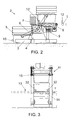
Figure 2 . Shows a close up of the lifting device that is included in the installation of the previous figure, in which, for reasons of simplification, a stack of trays is presented in which only a small number of them is shown although the system is planned to work with stacks of around 25 trays. -
Figure 3 . This shows a side-view close up of the separating machine that is included in the installation ofFigure 1 . -
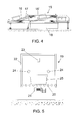
Figure 4 . It shows a side-view close up of the overturning machine that is included in the installation ofFigure 1 . -
Figure 5 . It shows a side-view and sectional close up of the machine that inspects for dirt by artificial vision that is included in the installation ofFigure 1 . -
Figure 6 . This shows a close-up profile of the diverter that is included in the installation ofFigure 1 , located at the outlet of the machine that inspects for dirt by artificial vision. -
Figure 7 . This shows a side-view close up of the stacking machine that is included in the installation ofFigure 1 . -
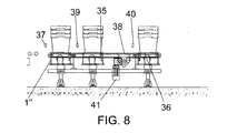
Figure 8 . This shows a close-up profile of the diverter that is located at the outlet of the installation ofFigure 1 . - In view of the indicated figures, and especially
Figures 1 and2 , it can be observed how the installation proposes having a motorised line of rollers (1), at whose entrance there is a lift (2), in charge of raising stacks of 25 trays from the floor to the roller line (1), incorporating a lower chassis (3), a photoelectric sensor (4) that detects the presence of the trays (5), so that using a pair of arms (5) driven by a geared motor group (7), the stack of trays is placed on a roller line driven by a geared motor group (9) moving this stack to the roller line (1). - In order to avoid collisions in raising and lowering the stacks, the machine includes two photoelectric barriers (10-10').
- The roller line (1) takes the stack to the separating machine (11), that shown in
Figure 3 , comprised of a column in whose middle area there is a section of rollers (14) continuing the roller line (1) next to which there are two sensors (32) to control the position of the stack at the time of entering the machine. - This column incorporates some pneumatic claws (15) that are closed on the sides of the tray, holding it, and consequently the rest of the trays are stacked into it above, so that to separate it the machine is situated at the level of the second tray from the bottom, it closes on it, holding it, and proceeds to move said tray vertically, so that the lower tray is automatically separated, immediately connecting the drive of the roller section (14) that takes the separated tray alone towards the overturning machine (15), that shown in
Figure 4 , which, through a pair of conveyor belts (16), open in their middle area and assisted on the ends by the respective overturning supports (17), allow in the first place to turn the tray over 180°, emptying its content into a bin (18), and subsequently returning to its initial position by means of the corresponding overturning. - It can be highlighted that between the lift (2) and the separator (11) there is a roller line section (1) with sufficient length as to permit accumulating several stacks of trays, including a photoelectric saturation sensor (12) and a pneumatic limit (13) that doses out and controls the entry of stacks to the separator.
- The outlet of the overturning machine is connected to a machine that inspects for dirt by artificial vision (19), in which there is a roller section (20), as a continuation of the roller line (1), a mechanism activated by means of a geared motor group (21). The machine includes a casing (22), open on both ends, in which a system of artificial vision is set up, which is comprised of a camera (23), a data processing unit, as well as LED projectors (24) that provide stable lighting conditions, so that through image-comparing software it detects the possible adhered dirt, as well as moisture, having provided that the flash of the camera (23) is done through a photoelectric sensor (25) that would detect the presence of the tray in the proper position to be photographed.
- At the outlet of this machine that inspects for dirt by artificial vision (19) the roller line (1) diverges into two branches, a first branch (1') that takes the clean trays to a stacking machine (26), and a second branch (1") that by means of a diverter (27), that shown in the close up of
Figure 6 , takes away the dirty trays for their proper cleaning. - This diverter (27) is automatically activated upon detection of a dirty tray, so that through a photoelectric sensor (33) the drive of the rollers of the branch (1') stops and some belts (28) driven by a geared motor group (29) start up and move the tray to the branch (1"), a position that is detected through the corresponding photoelectric sensor (30), with this branch (1") including a photoelectric sensor (31) for the saturation of the line.
- The aforementioned stacking machine (26) will have a structure similar to that of the separator (11), with a column in the middle of which is a section of rollers (14'), two photoelectric sensors (32') for the control of the tray's position at the time it enters the machine, as well as some pneumatic claws (15') that close on the trays and move vertically, so that in this case, the claws (15) also move to the position immediately above the lower tray in order to proceed to open, depositing in that tray the set of trays that may have accumulated and stacked, in order to then move downwards a certain distance in order to hold the lower tray, and raise the entire stack allowing the entry of a new tray, and inserting in it the accumulated stack, repeating the process until reaching the programmed stack level.
- Finally, and as an option, at the outlet of the installation there can be a second diverter (34), in charge of taking the checked and stacked trays to the two warehouses with rollers (35) and (36), for which a photoelectric sensor (37) to stop/start the motion of the corresponding rollers of the stopped line (1") after which some belts (3 8) connected to a geared motor group (41) start up which will divert crosswise the stacks of trays towards the corresponding roller warehouses (35) and (36), which will have photoelectric sensors (39-40) to stop the corresponding belts and activate the complementary rollers.
Claims (6)
- Installation for the processing of trays, characterised by being comprised by a roller line (1) at the entrance of which is set up a lifting machine (), equipped with means for lifting a stack of trays up to the level of the conveyor rollers of the roller line (1), a roller line (1) that, after a warehouse section includes a separating machine (11), equipped with hydraulically driven claws (15) that can move vertically, formally and dimensionally appropriate for separating the stack into units by means of raising the stack, after which an overturning machine (15) is set up, in which there is a series of slanted conveyor belts (16-16') and rotating supports that receive and overturn the trays, by which the tray is overturned through the simple effect of gravity; after this overturning machine (15) a machine to inspect for dirt by artificial vision (19) is set up, equipped with a camera connected to hardware with a software program through which possible dirt adhered to the trays, as well as moisture, is detected, including at the outlet of this machine two branches, one branch (1") diverts the trays that are considered not to have passed the required standards of cleanliness, and a main branch (1') that leads to a stacking machine (26'), with a structure similar to that of the separating machine (11), but with the opposite function.
- Installation for the processing of trays, according to claim 1, characterised by setting up at the outlet of the stacker (26) a diverter (34) in which a series of belts (38) are included driven by a geared motor group (41), that, through the use of a series of photoelectric sensors (37, 30, 40) to position the stacks of trays, divert them towards different roller warehouses (35-36).
- Installation for the processing of trays, according to claim 1, characterised by the lift (2) including a lower chassis (3) on which there is a photoelectric sensor (4) that detects the presence of trays (5), having a pair of arms (6) that lift the stack of trays, driven by a geared motor group (7), that discharge said stack on a line of rollers driven by a geared motor group (9) aligned with the roller line (1), having provided that the machine with two photoelectric barriers (10-10') to limit the movement of the arms (6).
- Installation for the processing of trays, according to claim 1, characterised by the separator (11); this is comprised by a column in whose middle area there is a section of rollers (14) continuing from the roller line (1) next to which there are two photoelectric sensors (32) for the control of the position of the stack at the time of entering the machine, a column that includes some pneumatic claws (15), equipped with means to close on the sides of the second tray from the bottom, as well as moving upwards.
- Installation for the processing of trays, according to claim 1, characterised by the machine to inspect for dirt by artificial vision (19); it includes a roller section (20), continuing the roller line (1), a mechanism driven by a geared motor group (21), as well as a casing (22), open on both ends, in which there is a system of artificial vision, which includes a camera (23), a data processing unit, as well as LED projectors (24) to light the inside of the tray, and a photoelectric sensor (25) for positioning the trays and shooting the camera (23), a set that includes dirt detection software, as well as moisture, for the discrimination of the trays leaving the machine.
- Installation for the processing of trays, according to claim 1, characterised by setting up, at the outlet of the machine to inspect for dirt by artificial vision (19), a diverter (27), which functions according to the indications sent by the preceding machine, equipped with a photoelectric sensor (33) so that it stops the rollers of branch (1') and activates some belts (28) driven by a geared motor group (29) that move the tray to the branch (1"), position that is detected through the corresponding photoelectric sensor (30), with this branch (1") including a photoelectric sensor (31) for the saturation of the line.
Priority Applications (3)
| Application Number | Priority Date | Filing Date | Title |
|---|---|---|---|
| EP09380120A EP2263944B1 (en) | 2009-06-17 | 2009-06-17 | Installation for the processing of trays |
| ES09380120T ES2358716T1 (en) | 2009-06-17 | 2009-06-17 | INSTALLATION FOR TREATMENT OF BUCKETS. |
| AT09380120T ATE555990T1 (en) | 2009-06-17 | 2009-06-17 | PLANT FOR PROCESSING SHELLS |
Applications Claiming Priority (1)
| Application Number | Priority Date | Filing Date | Title |
|---|---|---|---|
| EP09380120A EP2263944B1 (en) | 2009-06-17 | 2009-06-17 | Installation for the processing of trays |
Publications (2)
| Publication Number | Publication Date |
|---|---|
| EP2263944A1 true EP2263944A1 (en) | 2010-12-22 |
| EP2263944B1 EP2263944B1 (en) | 2012-05-02 |
Family
ID=41127898
Family Applications (1)
| Application Number | Title | Priority Date | Filing Date |
|---|---|---|---|
| EP09380120A Not-in-force EP2263944B1 (en) | 2009-06-17 | 2009-06-17 | Installation for the processing of trays |
Country Status (3)
| Country | Link |
|---|---|
| EP (1) | EP2263944B1 (en) |
| AT (1) | ATE555990T1 (en) |
| ES (1) | ES2358716T1 (en) |
Cited By (7)
| Publication number | Priority date | Publication date | Assignee | Title |
|---|---|---|---|---|
| WO2016173739A1 (en) * | 2015-04-30 | 2016-11-03 | Marianne Zippel | Method and inspection system for determining and checking the degree of surface cleanliness of industrially cleaned workpieces or machine parts |
| CN106124520A (en) * | 2016-08-26 | 2016-11-16 | 武汉捷普瑞科技有限公司 | A kind of full-automatic loading and unloading and the device of vision-based detection |
| WO2020221767A1 (en) * | 2019-05-02 | 2020-11-05 | Ocado Innovation Limited | An apparatus and method for imaging containers |
| US20210121041A1 (en) * | 2019-09-02 | 2021-04-29 | Norman Schmidt | Pan cleaning machine and a method of operating the machine to clean pans |
| US20210169303A1 (en) * | 2019-09-02 | 2021-06-10 | Food Machinery Ltd. | Pan cleaning system and improved cleaning stations |
| CN114308743A (en) * | 2021-12-21 | 2022-04-12 | 重庆特斯联智慧科技股份有限公司 | Commodity security inspection and loading system for logistics robot |
| WO2022189129A1 (en) * | 2021-03-08 | 2022-09-15 | Grinnory Ip B.V. | An ultraviolet radiation cleaning system for baggage trays in an airport security environment |
Citations (5)
| Publication number | Priority date | Publication date | Assignee | Title |
|---|---|---|---|---|
| GB710251A (en) * | 1950-05-18 | 1954-06-09 | Samuel John Young | Improvements in and relating to machines for emptying crates and like containers of bodies such as crown corks |
| GB900058A (en) * | 1959-11-19 | 1962-07-04 | Samuel John Young | Apparatus for inverting crates and like containers |
| US3651937A (en) * | 1969-05-02 | 1972-03-28 | Hermann Kronseder | Automatic inspection machine |
| DE4116183A1 (en) * | 1991-05-17 | 1992-11-19 | Kronseder Maschf Krones | Machine for sorting re-usable beverage bottles - has chute to collect bottles and rotating disc to arrange bottles in line for refilling |
| FR2746502A1 (en) * | 1996-03-22 | 1997-09-26 | Kronenbourg Brasseries | Detecting glass fragments in glass containers |
-
2009
- 2009-06-17 AT AT09380120T patent/ATE555990T1/en active
- 2009-06-17 EP EP09380120A patent/EP2263944B1/en not_active Not-in-force
- 2009-06-17 ES ES09380120T patent/ES2358716T1/en active Pending
Patent Citations (5)
| Publication number | Priority date | Publication date | Assignee | Title |
|---|---|---|---|---|
| GB710251A (en) * | 1950-05-18 | 1954-06-09 | Samuel John Young | Improvements in and relating to machines for emptying crates and like containers of bodies such as crown corks |
| GB900058A (en) * | 1959-11-19 | 1962-07-04 | Samuel John Young | Apparatus for inverting crates and like containers |
| US3651937A (en) * | 1969-05-02 | 1972-03-28 | Hermann Kronseder | Automatic inspection machine |
| DE4116183A1 (en) * | 1991-05-17 | 1992-11-19 | Kronseder Maschf Krones | Machine for sorting re-usable beverage bottles - has chute to collect bottles and rotating disc to arrange bottles in line for refilling |
| FR2746502A1 (en) * | 1996-03-22 | 1997-09-26 | Kronenbourg Brasseries | Detecting glass fragments in glass containers |
Cited By (22)
| Publication number | Priority date | Publication date | Assignee | Title |
|---|---|---|---|---|
| WO2016173739A1 (en) * | 2015-04-30 | 2016-11-03 | Marianne Zippel | Method and inspection system for determining and checking the degree of surface cleanliness of industrially cleaned workpieces or machine parts |
| CN106124520A (en) * | 2016-08-26 | 2016-11-16 | 武汉捷普瑞科技有限公司 | A kind of full-automatic loading and unloading and the device of vision-based detection |
| CN106124520B (en) * | 2016-08-26 | 2018-08-28 | 武汉捷普瑞科技有限公司 | A kind of device of full-automatic loading and unloading and vision-based detection |
| AU2020264742B2 (en) * | 2019-05-02 | 2023-04-13 | Ocado Innovation Limited | An apparatus and method for imaging containers |
| JP2022531420A (en) * | 2019-05-02 | 2022-07-06 | オカド・イノベーション・リミテッド | Equipment and methods for imaging containers |
| CN113825709B (en) * | 2019-05-02 | 2024-05-28 | 奥卡多创新有限公司 | Container imaging apparatus and method |
| JP2023166477A (en) * | 2019-05-02 | 2023-11-21 | オカド・イノベーション・リミテッド | Control unit and preservation system |
| GB2584789B (en) * | 2019-05-02 | 2021-09-22 | Ocado Innovation Ltd | An apparatus and method for imaging containers |
| CN113825709A (en) * | 2019-05-02 | 2021-12-21 | 奥卡多创新有限公司 | Vessel imaging apparatus and method |
| KR20220005052A (en) * | 2019-05-02 | 2022-01-12 | 오카도 이노베이션 리미티드 | Apparatus and method for imaging containers |
| GB2598688A (en) * | 2019-05-02 | 2022-03-09 | Ocado Innovation Ltd | An apparatus and method for imaging containers |
| GB2598688B (en) * | 2019-05-02 | 2023-07-19 | Ocado Innovation Ltd | An apparatus and method for imaging containers |
| GB2584789A (en) * | 2019-05-02 | 2020-12-16 | Ocado Innovation Ltd | An apparatus and method for imaging containers |
| WO2020221767A1 (en) * | 2019-05-02 | 2020-11-05 | Ocado Innovation Limited | An apparatus and method for imaging containers |
| US20210169303A1 (en) * | 2019-09-02 | 2021-06-10 | Food Machinery Ltd. | Pan cleaning system and improved cleaning stations |
| US20210121041A1 (en) * | 2019-09-02 | 2021-04-29 | Norman Schmidt | Pan cleaning machine and a method of operating the machine to clean pans |
| US12102277B2 (en) * | 2019-09-02 | 2024-10-01 | Food Machinery Engineering, LMTD | Pan cleaning system and improved cleaning stations |
| US12357145B2 (en) * | 2019-09-02 | 2025-07-15 | Food Machinery Engineering, LMTD | Pan cleaning machine and a method of operating the machine to clean pans |
| NL2027720B1 (en) * | 2021-03-08 | 2022-09-26 | One Tray S R L | An ultraviolet radiation cleaning system for baggage trays in an airport security environment |
| WO2022189129A1 (en) * | 2021-03-08 | 2022-09-15 | Grinnory Ip B.V. | An ultraviolet radiation cleaning system for baggage trays in an airport security environment |
| CN114308743A (en) * | 2021-12-21 | 2022-04-12 | 重庆特斯联智慧科技股份有限公司 | Commodity security inspection and loading system for logistics robot |
| CN114308743B (en) * | 2021-12-21 | 2024-04-05 | 重庆特斯联智慧科技股份有限公司 | Logistics robot-oriented article security inspection and loading system |
Also Published As
| Publication number | Publication date |
|---|---|
| EP2263944B1 (en) | 2012-05-02 |
| ATE555990T1 (en) | 2012-05-15 |
| ES2358716T1 (en) | 2011-05-13 |
Similar Documents
| Publication | Publication Date | Title |
|---|---|---|
| EP2263944B1 (en) | Installation for the processing of trays | |
| EP2794439B1 (en) | Depalletizing system and removal unit | |
| EP2125587B1 (en) | Apparatus and method for transferring part loads | |
| EP2573012B1 (en) | Device and method for singulating piece goods to be stored in an automated storage | |
| CN102781796B (en) | Waste separating device | |
| EP3814252B1 (en) | Apparatus and method for inspecting suspendedly conveyable transport bags | |
| DE69720094T2 (en) | Feeder for successively feeding objects to an alignment mechanism | |
| EP2263943A1 (en) | Tray overturning device | |
| CA2970735A1 (en) | Sorting system with multiple sorting devices | |
| US20230011190A1 (en) | Stacking and packaging device | |
| AT521112A1 (en) | Robotic system for gripping a product in a storage and picking system and method of operation therefor | |
| JPH02150221A (en) | Device and method for delivering and piling chicken housing container | |
| US10583998B2 (en) | Egg tray stacking machine | |
| CA2629264A1 (en) | System and method of sorting elongated wood boards for preparing rows | |
| US12428245B2 (en) | Device and conveyance system for packaging elongated items | |
| CN110540032A (en) | Feeding machine | |
| US20060219610A1 (en) | Tray stacking and buffer system and method of use | |
| CN103979298B (en) | ATM palletizer | |
| CN212821173U (en) | An intelligent sorting system for iron blocks | |
| JP2524927B2 (en) | Conveyor retention prevention device | |
| CN212607458U (en) | Automatic iron block pouring machine | |
| JPH05185039A (en) | Automatic tableware screening device | |
| DE202008001683U1 (en) | Automated storage device for a pharmacy warehouse | |
| CN107848716A (en) | Transport chute with drive mechanism | |
| JPS61136820A (en) | Cage piling-up machine |
Legal Events
| Date | Code | Title | Description |
|---|---|---|---|
| PUAI | Public reference made under article 153(3) epc to a published international application that has entered the european phase |
Free format text: ORIGINAL CODE: 0009012 |
|
| AK | Designated contracting states |
Kind code of ref document: A1 Designated state(s): AT BE BG CH CY CZ DE DK EE ES FI FR GB GR HR HU IE IS IT LI LT LU LV MC MK MT NL NO PL PT RO SE SI SK TR |
|
| AX | Request for extension of the european patent |
Extension state: AL BA RS |
|
| 17P | Request for examination filed |
Effective date: 20110325 |
|
| GRAP | Despatch of communication of intention to grant a patent |
Free format text: ORIGINAL CODE: EPIDOSNIGR1 |
|
| GRAS | Grant fee paid |
Free format text: ORIGINAL CODE: EPIDOSNIGR3 |
|
| GRAA | (expected) grant |
Free format text: ORIGINAL CODE: 0009210 |
|
| AK | Designated contracting states |
Kind code of ref document: B1 Designated state(s): AT BE BG CH CY CZ DE DK EE ES FI FR GB GR HR HU IE IS IT LI LT LU LV MC MK MT NL NO PL PT RO SE SI SK TR |
|
| REG | Reference to a national code |
Ref country code: GB Ref legal event code: FG4D |
|
| REG | Reference to a national code |
Ref country code: AT Ref legal event code: REF Ref document number: 555990 Country of ref document: AT Kind code of ref document: T Effective date: 20120515 Ref country code: CH Ref legal event code: EP |
|
| REG | Reference to a national code |
Ref country code: IE Ref legal event code: FG4D |
|
| REG | Reference to a national code |
Ref country code: DE Ref legal event code: R096 Ref document number: 602009006754 Country of ref document: DE Effective date: 20120621 |
|
| REG | Reference to a national code |
Ref country code: NL Ref legal event code: VDEP Effective date: 20120502 |
|
| REG | Reference to a national code |
Ref country code: LT Ref legal event code: MG4D Effective date: 20120502 |
|
| PG25 | Lapsed in a contracting state [announced via postgrant information from national office to epo] |
Ref country code: LT Free format text: LAPSE BECAUSE OF FAILURE TO SUBMIT A TRANSLATION OF THE DESCRIPTION OR TO PAY THE FEE WITHIN THE PRESCRIBED TIME-LIMIT Effective date: 20120502 Ref country code: CY Free format text: LAPSE BECAUSE OF FAILURE TO SUBMIT A TRANSLATION OF THE DESCRIPTION OR TO PAY THE FEE WITHIN THE PRESCRIBED TIME-LIMIT Effective date: 20120502 Ref country code: PL Free format text: LAPSE BECAUSE OF FAILURE TO SUBMIT A TRANSLATION OF THE DESCRIPTION OR TO PAY THE FEE WITHIN THE PRESCRIBED TIME-LIMIT Effective date: 20120502 Ref country code: SE Free format text: LAPSE BECAUSE OF FAILURE TO SUBMIT A TRANSLATION OF THE DESCRIPTION OR TO PAY THE FEE WITHIN THE PRESCRIBED TIME-LIMIT Effective date: 20120502 Ref country code: NO Free format text: LAPSE BECAUSE OF FAILURE TO SUBMIT A TRANSLATION OF THE DESCRIPTION OR TO PAY THE FEE WITHIN THE PRESCRIBED TIME-LIMIT Effective date: 20120802 Ref country code: IS Free format text: LAPSE BECAUSE OF FAILURE TO SUBMIT A TRANSLATION OF THE DESCRIPTION OR TO PAY THE FEE WITHIN THE PRESCRIBED TIME-LIMIT Effective date: 20120902 Ref country code: FI Free format text: LAPSE BECAUSE OF FAILURE TO SUBMIT A TRANSLATION OF THE DESCRIPTION OR TO PAY THE FEE WITHIN THE PRESCRIBED TIME-LIMIT Effective date: 20120502 |
|
| REG | Reference to a national code |
Ref country code: AT Ref legal event code: MK05 Ref document number: 555990 Country of ref document: AT Kind code of ref document: T Effective date: 20120502 |
|
| PG25 | Lapsed in a contracting state [announced via postgrant information from national office to epo] |
Ref country code: HR Free format text: LAPSE BECAUSE OF FAILURE TO SUBMIT A TRANSLATION OF THE DESCRIPTION OR TO PAY THE FEE WITHIN THE PRESCRIBED TIME-LIMIT Effective date: 20120502 Ref country code: PT Free format text: LAPSE BECAUSE OF FAILURE TO SUBMIT A TRANSLATION OF THE DESCRIPTION OR TO PAY THE FEE WITHIN THE PRESCRIBED TIME-LIMIT Effective date: 20120903 Ref country code: GR Free format text: LAPSE BECAUSE OF FAILURE TO SUBMIT A TRANSLATION OF THE DESCRIPTION OR TO PAY THE FEE WITHIN THE PRESCRIBED TIME-LIMIT Effective date: 20120803 Ref country code: LV Free format text: LAPSE BECAUSE OF FAILURE TO SUBMIT A TRANSLATION OF THE DESCRIPTION OR TO PAY THE FEE WITHIN THE PRESCRIBED TIME-LIMIT Effective date: 20120502 Ref country code: SI Free format text: LAPSE BECAUSE OF FAILURE TO SUBMIT A TRANSLATION OF THE DESCRIPTION OR TO PAY THE FEE WITHIN THE PRESCRIBED TIME-LIMIT Effective date: 20120502 |
|
| PG25 | Lapsed in a contracting state [announced via postgrant information from national office to epo] |
Ref country code: BE Free format text: LAPSE BECAUSE OF FAILURE TO SUBMIT A TRANSLATION OF THE DESCRIPTION OR TO PAY THE FEE WITHIN THE PRESCRIBED TIME-LIMIT Effective date: 20120502 |
|
| PG25 | Lapsed in a contracting state [announced via postgrant information from national office to epo] |
Ref country code: RO Free format text: LAPSE BECAUSE OF FAILURE TO SUBMIT A TRANSLATION OF THE DESCRIPTION OR TO PAY THE FEE WITHIN THE PRESCRIBED TIME-LIMIT Effective date: 20120502 Ref country code: EE Free format text: LAPSE BECAUSE OF FAILURE TO SUBMIT A TRANSLATION OF THE DESCRIPTION OR TO PAY THE FEE WITHIN THE PRESCRIBED TIME-LIMIT Effective date: 20120502 Ref country code: DK Free format text: LAPSE BECAUSE OF FAILURE TO SUBMIT A TRANSLATION OF THE DESCRIPTION OR TO PAY THE FEE WITHIN THE PRESCRIBED TIME-LIMIT Effective date: 20120502 Ref country code: NL Free format text: LAPSE BECAUSE OF FAILURE TO SUBMIT A TRANSLATION OF THE DESCRIPTION OR TO PAY THE FEE WITHIN THE PRESCRIBED TIME-LIMIT Effective date: 20120502 Ref country code: SK Free format text: LAPSE BECAUSE OF FAILURE TO SUBMIT A TRANSLATION OF THE DESCRIPTION OR TO PAY THE FEE WITHIN THE PRESCRIBED TIME-LIMIT Effective date: 20120502 Ref country code: AT Free format text: LAPSE BECAUSE OF FAILURE TO SUBMIT A TRANSLATION OF THE DESCRIPTION OR TO PAY THE FEE WITHIN THE PRESCRIBED TIME-LIMIT Effective date: 20120502 Ref country code: MC Free format text: LAPSE BECAUSE OF NON-PAYMENT OF DUE FEES Effective date: 20120630 Ref country code: CZ Free format text: LAPSE BECAUSE OF FAILURE TO SUBMIT A TRANSLATION OF THE DESCRIPTION OR TO PAY THE FEE WITHIN THE PRESCRIBED TIME-LIMIT Effective date: 20120502 |
|
| PG25 | Lapsed in a contracting state [announced via postgrant information from national office to epo] |
Ref country code: IT Free format text: LAPSE BECAUSE OF FAILURE TO SUBMIT A TRANSLATION OF THE DESCRIPTION OR TO PAY THE FEE WITHIN THE PRESCRIBED TIME-LIMIT Effective date: 20120502 Ref country code: MK Free format text: LAPSE BECAUSE OF FAILURE TO SUBMIT A TRANSLATION OF THE DESCRIPTION OR TO PAY THE FEE WITHIN THE PRESCRIBED TIME-LIMIT Effective date: 20120502 |
|
| PLBE | No opposition filed within time limit |
Free format text: ORIGINAL CODE: 0009261 |
|
| STAA | Information on the status of an ep patent application or granted ep patent |
Free format text: STATUS: NO OPPOSITION FILED WITHIN TIME LIMIT |
|
| REG | Reference to a national code |
Ref country code: IE Ref legal event code: MM4A |
|
| REG | Reference to a national code |
Ref country code: FR Ref legal event code: ST Effective date: 20130228 |
|
| 26N | No opposition filed |
Effective date: 20130205 |
|
| REG | Reference to a national code |
Ref country code: DE Ref legal event code: R119 Ref document number: 602009006754 Country of ref document: DE Effective date: 20130101 |
|
| PG25 | Lapsed in a contracting state [announced via postgrant information from national office to epo] |
Ref country code: ES Free format text: LAPSE BECAUSE OF FAILURE TO SUBMIT A TRANSLATION OF THE DESCRIPTION OR TO PAY THE FEE WITHIN THE PRESCRIBED TIME-LIMIT Effective date: 20120813 Ref country code: FR Free format text: LAPSE BECAUSE OF NON-PAYMENT OF DUE FEES Effective date: 20120702 Ref country code: DE Free format text: LAPSE BECAUSE OF NON-PAYMENT OF DUE FEES Effective date: 20130101 Ref country code: IE Free format text: LAPSE BECAUSE OF NON-PAYMENT OF DUE FEES Effective date: 20120617 |
|
| PG25 | Lapsed in a contracting state [announced via postgrant information from national office to epo] |
Ref country code: MT Free format text: LAPSE BECAUSE OF FAILURE TO SUBMIT A TRANSLATION OF THE DESCRIPTION OR TO PAY THE FEE WITHIN THE PRESCRIBED TIME-LIMIT Effective date: 20120502 Ref country code: BG Free format text: LAPSE BECAUSE OF FAILURE TO SUBMIT A TRANSLATION OF THE DESCRIPTION OR TO PAY THE FEE WITHIN THE PRESCRIBED TIME-LIMIT Effective date: 20120802 |
|
| REG | Reference to a national code |
Ref country code: CH Ref legal event code: PL |
|
| GBPC | Gb: european patent ceased through non-payment of renewal fee |
Effective date: 20130617 |
|
| PG25 | Lapsed in a contracting state [announced via postgrant information from national office to epo] |
Ref country code: TR Free format text: LAPSE BECAUSE OF FAILURE TO SUBMIT A TRANSLATION OF THE DESCRIPTION OR TO PAY THE FEE WITHIN THE PRESCRIBED TIME-LIMIT Effective date: 20120502 Ref country code: CH Free format text: LAPSE BECAUSE OF NON-PAYMENT OF DUE FEES Effective date: 20130630 Ref country code: LI Free format text: LAPSE BECAUSE OF NON-PAYMENT OF DUE FEES Effective date: 20130630 Ref country code: GB Free format text: LAPSE BECAUSE OF NON-PAYMENT OF DUE FEES Effective date: 20130617 |
|
| PG25 | Lapsed in a contracting state [announced via postgrant information from national office to epo] |
Ref country code: LU Free format text: LAPSE BECAUSE OF NON-PAYMENT OF DUE FEES Effective date: 20120617 |
|
| PG25 | Lapsed in a contracting state [announced via postgrant information from national office to epo] |
Ref country code: HU Free format text: LAPSE BECAUSE OF FAILURE TO SUBMIT A TRANSLATION OF THE DESCRIPTION OR TO PAY THE FEE WITHIN THE PRESCRIBED TIME-LIMIT Effective date: 20090617 |