EP2263603B1 - Method for tuning a spring element used in a resonant driving system for an appliance which includes a work piece - Google Patents
Method for tuning a spring element used in a resonant driving system for an appliance which includes a work piece Download PDFInfo
- Publication number
- EP2263603B1 EP2263603B1 EP10178883.4A EP10178883A EP2263603B1 EP 2263603 B1 EP2263603 B1 EP 2263603B1 EP 10178883 A EP10178883 A EP 10178883A EP 2263603 B1 EP2263603 B1 EP 2263603B1
- Authority
- EP
- European Patent Office
- Prior art keywords
- spring
- cut
- spring element
- appliance
- frequency
- Prior art date
- Legal status (The legal status is an assumption and is not a legal conclusion. Google has not performed a legal analysis and makes no representation as to the accuracy of the status listed.)
- Expired - Lifetime
Links
- 238000000034 method Methods 0.000 title claims abstract description 27
- 230000001419 dependent effect Effects 0.000 claims abstract 2
- 230000009471 action Effects 0.000 claims description 26
- 239000000463 material Substances 0.000 claims description 8
- 230000008859 change Effects 0.000 claims description 3
- 230000009467 reduction Effects 0.000 claims description 2
- 230000003247 decreasing effect Effects 0.000 abstract description 5
- 230000033001 locomotion Effects 0.000 description 39
- 238000006243 chemical reaction Methods 0.000 description 26
- 238000004519 manufacturing process Methods 0.000 description 14
- 238000005452 bending Methods 0.000 description 5
- 238000013459 approach Methods 0.000 description 4
- 239000002184 metal Substances 0.000 description 3
- 230000008569 process Effects 0.000 description 3
- 230000000712 assembly Effects 0.000 description 2
- 238000000429 assembly Methods 0.000 description 2
- 230000008901 benefit Effects 0.000 description 2
- 238000012360 testing method Methods 0.000 description 2
- 238000013016 damping Methods 0.000 description 1
- 230000000694 effects Effects 0.000 description 1
- 239000013536 elastomeric material Substances 0.000 description 1
- 239000012530 fluid Substances 0.000 description 1
- 230000009021 linear effect Effects 0.000 description 1
- 230000013011 mating Effects 0.000 description 1
- 238000005259 measurement Methods 0.000 description 1
- 230000004048 modification Effects 0.000 description 1
- 238000012986 modification Methods 0.000 description 1
- 238000000926 separation method Methods 0.000 description 1
- 238000006467 substitution reaction Methods 0.000 description 1
- 239000013585 weight reducing agent Substances 0.000 description 1
Images


Classifications
-
- A—HUMAN NECESSITIES
- A61—MEDICAL OR VETERINARY SCIENCE; HYGIENE
- A61C—DENTISTRY; APPARATUS OR METHODS FOR ORAL OR DENTAL HYGIENE
- A61C17/00—Devices for cleaning, polishing, rinsing or drying teeth, teeth cavities or prostheses; Saliva removers; Dental appliances for receiving spittle
- A61C17/16—Power-driven cleaning or polishing devices
- A61C17/22—Power-driven cleaning or polishing devices with brushes, cushions, cups, or the like
- A61C17/32—Power-driven cleaning or polishing devices with brushes, cushions, cups, or the like reciprocating or oscillating
- A61C17/34—Power-driven cleaning or polishing devices with brushes, cushions, cups, or the like reciprocating or oscillating driven by electric motor
-
- A—HUMAN NECESSITIES
- A61—MEDICAL OR VETERINARY SCIENCE; HYGIENE
- A61C—DENTISTRY; APPARATUS OR METHODS FOR ORAL OR DENTAL HYGIENE
- A61C17/00—Devices for cleaning, polishing, rinsing or drying teeth, teeth cavities or prostheses; Saliva removers; Dental appliances for receiving spittle
- A61C17/16—Power-driven cleaning or polishing devices
- A61C17/22—Power-driven cleaning or polishing devices with brushes, cushions, cups, or the like
- A61C17/32—Power-driven cleaning or polishing devices with brushes, cushions, cups, or the like reciprocating or oscillating
- A61C17/34—Power-driven cleaning or polishing devices with brushes, cushions, cups, or the like reciprocating or oscillating driven by electric motor
- A61C17/3409—Power-driven cleaning or polishing devices with brushes, cushions, cups, or the like reciprocating or oscillating driven by electric motor characterized by the movement of the brush body
- A61C17/3481—Vibrating brush body, e.g. by using eccentric weights
-
- A—HUMAN NECESSITIES
- A61—MEDICAL OR VETERINARY SCIENCE; HYGIENE
- A61C—DENTISTRY; APPARATUS OR METHODS FOR ORAL OR DENTAL HYGIENE
- A61C17/00—Devices for cleaning, polishing, rinsing or drying teeth, teeth cavities or prostheses; Saliva removers; Dental appliances for receiving spittle
- A61C17/16—Power-driven cleaning or polishing devices
- A61C17/22—Power-driven cleaning or polishing devices with brushes, cushions, cups, or the like
- A61C17/32—Power-driven cleaning or polishing devices with brushes, cushions, cups, or the like reciprocating or oscillating
- A61C17/34—Power-driven cleaning or polishing devices with brushes, cushions, cups, or the like reciprocating or oscillating driven by electric motor
- A61C17/3409—Power-driven cleaning or polishing devices with brushes, cushions, cups, or the like reciprocating or oscillating driven by electric motor characterized by the movement of the brush body
- A61C17/3418—Rotation around the axis of the toothbrush handle
-
- B—PERFORMING OPERATIONS; TRANSPORTING
- B26—HAND CUTTING TOOLS; CUTTING; SEVERING
- B26B—HAND-HELD CUTTING TOOLS NOT OTHERWISE PROVIDED FOR
- B26B19/00—Clippers or shavers operating with a plurality of cutting edges, e.g. hair clippers, dry shavers
- B26B19/28—Drive layout for hair clippers or dry shavers, e.g. providing for electromotive drive
- B26B19/282—Motors without a rotating central drive shaft, e.g. linear motors
-
- F—MECHANICAL ENGINEERING; LIGHTING; HEATING; WEAPONS; BLASTING
- F16—ENGINEERING ELEMENTS AND UNITS; GENERAL MEASURES FOR PRODUCING AND MAINTAINING EFFECTIVE FUNCTIONING OF MACHINES OR INSTALLATIONS; THERMAL INSULATION IN GENERAL
- F16H—GEARING
- F16H25/00—Gearings comprising primarily only cams, cam-followers and screw-and-nut mechanisms
- F16H25/18—Gearings comprising primarily only cams, cam-followers and screw-and-nut mechanisms for conveying or interconverting oscillating or reciprocating motions
-
- Y—GENERAL TAGGING OF NEW TECHNOLOGICAL DEVELOPMENTS; GENERAL TAGGING OF CROSS-SECTIONAL TECHNOLOGIES SPANNING OVER SEVERAL SECTIONS OF THE IPC; TECHNICAL SUBJECTS COVERED BY FORMER USPC CROSS-REFERENCE ART COLLECTIONS [XRACs] AND DIGESTS
- Y10—TECHNICAL SUBJECTS COVERED BY FORMER USPC
- Y10T—TECHNICAL SUBJECTS COVERED BY FORMER US CLASSIFICATION
- Y10T29/00—Metal working
- Y10T29/49—Method of mechanical manufacture
- Y10T29/49718—Repairing
Definitions
- the invention concerns a method for tuning the spring structure of small appliances to a selected natural resonant frequency or amplitude during manufacture.
- Small appliances such as, for instance, toothbrushes, comprise a spring structure for converting a side-to-side driving action into a rotary work piece action.
- Small appliances have various work piece motions.
- the drive motion is the same as the work piece motion; in other cases, it is desirable to convert a particular drive motion into a different work piece motion, such as a side-to-side drive motion to a rotary motion.
- the magnetic driver shown in U.S. Patent No. 5,189,751 moves one end of an elongated pivoted arm to which is attached a toothbrush element, in a side-to-side (back and forth), slightly arcuate manner.
- the work piece vibrates in a particular manner accordingly. While that work piece motion does provide good results, it may be desirable, for various reasons, to have the work piece rotate through a selected arc (rotational motion), while retaining the side-to-side driving action. This would require, however, a motion conversion assembly, from side-to-side to rotational.
- Apparatus for converting a side-by-side driving action, such as produced by the electromagnetic driver of the '751 patent, to a work piece rotary action are known.
- Some devices involve linkage-type arrangements. However, such linkage arrangements frequently have undesirable backlash action, which can cause damping, vibration and noise.
- Pivot assemblies are also used, in combination with a spring element. Torsion springs can be used, but they are usually made from coil-type springs, which typically do not combine the required radial stiffness with an acceptably low torsion spring rate.
- Most of these known devices require various bearing structures, which are often complex, noisy and unreliable. Bearings also have their own backlash conditions.
- spring elements are often used as part of a driving assembly in a resonant system, such as the spring assembly of the present invention.
- These spring assemblies usually require either tuning in some fashion or very close manufacturing tolerances, so that the resonant frequency of the spring assembly is acceptably close to the operating or driving frequency of the device, to maintain the efficiency of the resonant system. It is desirable that the tuning be accomplished with a simple method which can be carried out during manufacture of the assembly so that the manufacturing tolerances of the appliance can be increased (greater tolerances), thereby decreasing the cost of manufacture of the appliance, as well as substantially reducing the number of appliances rejected during manufacture.
- a method of tuning a vibrator structure such as a tuning fork is disclosed in US 3 759 133 .
- the method disclosed therein shows the features of the preamble of claim 1.
- the method comprises the step of removing or adding material to adjust the frequency of the vibrator structure.
- a method for tuning a spring element used in a resonant driving system for an appliance which includes a work piece and which has a driving frequency is known from GB 1 403 606 A .
- the present invention comprises the step of changing the spring rate of the spring element, and hence its resonant frequency, by removing a portion of the spring element to decrease its spring rate or adding material to the spring element to increase its spring rate sufficiently that it closely approximates the driving frequency of the appliance, and is characterised in that the work piece has a rotatable action.
- the spring element comprises a leaf spring assembly, and wherein said portion of the spring element is removed by cutting a part of the leaf spring away from one edge thereof.
- the step of cutting includes the steps of controlling the width of the cut, the length of the cut, the curvature of the cut and the position of the cut along the length of the leaf spring to provide the required change in spring rate.
- the configuration of the removed portion may define a gradual reduction of the spring width over the length of the cut, with the maximum extent of the cut approximately at the midpoint of the cut, the cut being located approximately midway between the two ends of the leaf spring.
- the removed portion may be a cut which is curved between the respective ends thereof.
- the spring element comprises two leaf springs positioned at a selected angle to each other, including the step of removing a portion of each leaf spring.
- the portion is removed from an interior portion of at least one of the leaf springs, the removed portion being football shaped.
- the appliance is a toothbrush having a rotatable work piece action.
- Figures 1 and 1A show a power toothbrush 10 which includes a handle portion 12 and a head portion 14.
- the handle portion includes a power source, such as a rechargeable
- Figures 1 and 1A are exploded views of a power toothbrush comprising a motion conversion assembly.
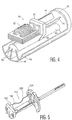
- Figure 2 is a perspective view of the motion conversion assembly portion of the toothbrush of Figure 1 .
- Figure 3 is an elevational view showing an angled orientation of a drive shaft and a brush arm of the motion conversion assembly relative to a longitudinal axis of the toothbrush.
- Figure 4 shows a modified motion conversion assembly used for a shaving appliance.
- Figure 5 shows the result of the frequency tuning method of the present invention on the motion conversion assembly of Figure 2 .
- Figures 1 and 1A show a power toothbrush 10 which includes a handle portion 12 and a head portion 14.
- the handle portion includes a power source, such as a rechargeable battery 16, and a drive assembly, shown generally at 18.
- the head portion 14 includes a work piece element, e.g. a brush head 20, which comprises a plurality of bristles arranged in a selected pattern, a brush head arm 22 on which brush head 10 is mounted, a motion conversion assembly, shown generally at 26, and a mounting assembly 27 for the motion conversion assembly.
- the motion conversion assembly 26 in the embodiment shown converts a linear action to rotation of a drive shaft 28 which extends into and joins with brush head arm 22 for rotation thereof and rotation of brush head 20.
- Head portion 14 also includes a nut element 30, which connects head portion 14 to handle portion 12 and to which the mounting assembly 27 is fixedly secured.
- the driving assembly 18 is an electromagnet, which produces a side-to-side force and cooperates in operation with two permanent magnets 32 mounted to a movable end piece 40 at the rear end of the motion conversion assembly 26 to move end piece 40 in a side-to-side slightly arcuate, translational manner.
- "Side-to-side" herein refers to a straight side-to-side motion or a side-to-side path which is slightly arcuate.
- the motion conversion assembly 26 converts the drive action of the drive assembly via a leaf spring arrangement into a twisting or rotational action of drive shaft 28, which in turn rotates brush head arm 22 and brush head 20 about the longitudinal axis A-A of drive shaft 28 ( Figure 2 ).
- the included angle (arc) of rotation of the brush head is approximately 11°, although this angle can be varied and is not an essential part of the present invention.
- the motion conversion assembly 26 is shown in more detail in Figure 2 . It includes movable end piece 40, which in the embodiment shown is made from a plastic material and is approximately 0.6 inches long, approximately 0.6 inches wide at its widest dimension, and approximately 0.1 inches thick. Extending from the rear face 44 of end piece 40 is a small, centrally located mounting stub 46. Mounted on stub 46 is a permanent magnet assembly, which in the embodiment shown comprises a metal mounting plate 50 ( Figure 1 ) and two spaced rectangular permanent magnets 32-32. Permanent magnets 32-32 interact with electromagnet 18 in handle 12 such that the movable end piece 40 moves from side-to-side in a slightly arcuate path.
- each leaf spring 60, 62 is approximately 1 inch long, 0.2 inches wide and approximately 0.02 inches thick.
- Leaf springs 60, 62 in the embodiment shown are made from metal. However, they could be made from other materials, such as plastic.
- the two leaf springs 60, 62 in the embodiment shown are positioned at an angle of 70° relative to each other.
- the two leaf springs extend between and are fixedly mounted to both movable end piece 40 and fixed end piece 64.
- Fixed end piece 64 is generally circular, approximately 0.1 inches thick, and in the embodiment shown is made from plastic. It has two opposed notch openings 67, 69 at the top and bottom portions thereof.
- the planes of the two springs 60 and 62 intersect at the center of rotation of the motion conversion assembly, where the drive shaft is located.
- drive shaft 28 is metal and is rectangular in cross-section.
- the leaf springs twist and also bend somewhat as well, producing a rotation of the drive shaft.
- the relative position and dimensions of the springs can be optimized to reduce stress in each spring independently.
- Drive shaft 28 in the embodiment shown extends through notched opening 69 in the fixed end piece 64, so that it is free to rotate relative to fixed end piece 64.
- Drive shaft 28 extends to and is joined to brush head arm 22, so that rotation of drive shaft 28 produced by the action of the motion conversion assembly produces a rotation of brush head arm 22 and brush head 20 mounted at the distal end thereof.
- the fixed end piece 64 is secured by mounting assembly 27 so that it does not rotate relative thereto.
- the mounting assembly 27 includes as a portion thereof a ring of plastic material 72, with two opposing flanges 74 and 76 which extend rearwardly there from.
- the two flanges 74 and 76 extend through the notched openings 67, 69 in the fixed end piece 64.
- the two flanges 74 and 76 are configured to mate with corresponding receiving portions (not shown) in handle 12 of the toothbrush to produce a secure mating connection between the mounting assembly 27 (and head portion 14) and handle 12.
- connecting nut element 30 Fitting over the mounting assembly 27 and the motion conversion assembly 26 is connecting nut element 30.
- the connecting nut element has threads 77 on its internal surface so that it can be screwed onto an external threaded portion 67 of the handle 12.
- the nut 30 clamps flanges 74 and 76 to the handle, with fixed end piece 64 being held in place by flanges 74 and 76.
- a flexible connecting member 78 which in the embodiment shown is made from an elastomeric material.
- the lower edge of connecting member 78 fits flush with upper edge 79 of nut 30.
- Member 78 extends to a seal element 77, which provides a fluid seal between brush head arm 22 and the upper end of connecting member 78.
- the side-to-side drive produced by the electromagnetic driver 18 in the handle (or any other side-to-side driver) produces a slightly arcuate action of movable end piece 40, resulting in a rotation of the brush head 20 through a specific angle.
- the two leaf springs 60 and 62 and the drive shaft 28 are mounted in the fixed and movable end pieces such that they extend at an angle ⁇ away from the longitudinal axis B-B of the toothbrush ( Figure 3 ).
- This angle is within the range of 5-15° and preferably 10°.
- This angle of the brush head arm provides an increased reach for the toothbrush into the user's mouth. This is an advantage in many instances.
- the center of rotation is on a different axis than the axis of the handle.
- While the embodiment described includes two separate leaf springs which are at a specific angle (70°) to each other, two separate leaf springs are not necessary.
- the separation angle could vary within a range of 90° ⁇ 40%.
- more than two leaf springs could be used, in a radial pattern, with the plane of the leaf springs intersecting the center of rotation of the drive shaft.
- the two leaf springs could be joined into a single leaf spring in a "V" or a "U” form, an open square or a rectangle. Other configurations are also possible.
- the drive shaft must be connected to the movable end piece portion of the system, with the springs.
- the drive shaft cannot be connected to any other part of the springs. This structure could be a single part.
- the spring element must be configured so that it is substantially less resistant to twisting than to bending, i.e. so that the side-to-side action of the movable end piece results in a twisting of the springs and a resulting rotation of the drive shaft.
- the arrangement shown and described herein produces such an action.
- Other spring arrangements could be used, however, for example, an arrangement of a wire form spring, an arrangement of a single-piece, multi-leaf spring, comprising three separate legs joined together at one end, or an arrangement having a plurality of spring elements which extend from a rear movable mounting member to a fixed mounting member in a somewhat basket-like arrangement.
- FIG. 4 shows an alternative application for the motion conversion assembly.
- This application which is an electric shaver 80, also includes a movable end piece 81 with permanent magnets, driven by a magnetic driver arrangement, shown generally at 82. Extending from the movable end piece 81 are the two angled leaf springs 84 and 86, which are fixedly secured at their other ends to a fixed end piece 88.
- a drive shaft 90 extends rearwardly from the fixed end piece 81, parallel with the leaf springs 84, 86. The drive shaft 90 is suspended from the movable end piece 81 by support elements 82 and extends beneath the driver assembly 82.
- This embodiment demonstrates that the position and arrangement of the drive shaft on which the work piece is mounted can take various configurations relative to the motion conversion spring assembly.
- a movable end piece is driven in a side-by-side fashion, with a spring assembly extending from the movable end piece to a fixed end piece, which produces a rotary action of the drive shaft which is mounted to the movable end piece and hence a rotary action of the work piece mounted thereon.
- a motion conversion spring assembly eliminates the need for any bearing elements or flex elements, primarily because there is little bending of the spring element. It is, however, a strong, reliable and effective structure. Furthermore, it is a resonant assembly, which can be matched to an operating (driving) frequency of the appliance. For instance, in the toothbrush embodiment, the desired operating frequency is approximately 261 Hz.
- the spring assembly can be arranged and constructed so that it provides rotational action at that frequency.
- the toothbrush of Figure 1 is a "resonant" system. That is, the natural resonant frequency of the mechanical elements of the system are designed to match the operating or driving frequency of the toothbrush, which in the case of the present toothbrush is approximately 261 Hz. Such a resonant system is more efficient than a non-resonant system.
- a method for tuning a resonant spring system of a high volume product using leaf springs.
- the present method can be used to either increase or decrease (tuning up or tuning down) the resonant frequency of the spring assembly to match the operating frequency.
- a first step of the process measurement of amplitude of the work piece is made at a test frequency or vice versa.
- a fixed amplitude can be used with a variable frequency or a fixed frequency can be used with a variable amplitude. Both techniques can be used for tuning. Tuning the spring assembly shifts the operating point of the spring assembly on the operating characteristic curves to match the desired operating frequency or amplitude.
- the point on the characteristic operating curve can be decreased (a decrease in frequency) by reducing the spring rate of the spring assembly.
- the operating point can be increased (an increase in frequency) by increasing the spring rate.
- tuning systems increase or decrease the inertia of the system by increasing or decreasing the weight of the spring system, this approach is often not very accurate and requires a fairly high amount of weight reduction or increase to produce the desired frequency matching effect.
- the focus is on increasing or decreasing the spring rate (instead of inertia) by changing the configuration of the spring assembly which, in the present case, are leaf springs.
- cut 110 reduces the spring width, as shown at 100, the cut being centered generally at a point equidistant between the two ends 102, 104 of the spring element 106, to minimize fatigue-generating stresses.
- the depth of the cut is selected to produce the degree of tuning required.
- the variables of the cut include the overall length of the cut, the configuration, i.e . the curvature of the cut, and the width of the cut. In the specific embodiment shown, the cut 110 is curved in configuration.
- cut configurations can be used.
- One alternative is a "football" shaped slot in the center of one or both springs. Variables for this cut include the location of the slot, the length and/or width of the slot and the curvature of the slot.
- the cut can be accomplished by a number of techniques, including a laser, a grinder or a conventional cutting tool. The manner in which the material is removed is not significant to the invention.
- a new motion conversion assembly from side-by-side to rotary action for an appliance such as a toothbrush
- leaf springs which are configured to be less resistant to twisting than to bending, even though there is some bending by the spring assembly, in addition to the twisting, to produce the desired rotary action of a drive shaft on which the work piece is mounted.
- High resistance to bending eliminates the need for bearings.
- the motion being converted is referred to as side-to-side, which includes a straight line movement as well as movement which includes a slight arc, as in the present embodiment.
- the work piece motion is rotary, about the axis of the drive shaft on which the work piece is mounted.
- a method has been disclosed for tuning a spring assembly system to change the resonant frequency of the system during manufacturing to conform to the desired operating frequency (driving frequency) of the system. This permits the use of less severe manufacturing tolerances.
Landscapes
- Health & Medical Sciences (AREA)
- Life Sciences & Earth Sciences (AREA)
- Dentistry (AREA)
- Epidemiology (AREA)
- Animal Behavior & Ethology (AREA)
- General Health & Medical Sciences (AREA)
- Public Health (AREA)
- Veterinary Medicine (AREA)
- Forests & Forestry (AREA)
- Engineering & Computer Science (AREA)
- Mechanical Engineering (AREA)
- Brushes (AREA)
- Transmission Devices (AREA)
- Reciprocating, Oscillating Or Vibrating Motors (AREA)
- Apparatuses For Generation Of Mechanical Vibrations (AREA)
- Input Circuits Of Receivers And Coupling Of Receivers And Audio Equipment (AREA)
- Springs (AREA)
Abstract
Description
- The invention concerns a method for tuning the spring structure of small appliances to a selected natural resonant frequency or amplitude during manufacture. Small appliances, such as, for instance, toothbrushes, comprise a spring structure for converting a side-to-side driving action into a rotary work piece action.
- Small appliances have various work piece motions. In some cases, the drive motion is the same as the work piece motion; in other cases, it is desirable to convert a particular drive motion into a different work piece motion, such as a side-to-side drive motion to a rotary motion. The magnetic driver shown in
U.S. Patent No. 5,189,751 moves one end of an elongated pivoted arm to which is attached a toothbrush element, in a side-to-side (back and forth), slightly arcuate manner. The work piece vibrates in a particular manner accordingly. While that work piece motion does provide good results, it may be desirable, for various reasons, to have the work piece rotate through a selected arc (rotational motion), while retaining the side-to-side driving action. This would require, however, a motion conversion assembly, from side-to-side to rotational. - Apparatus for converting a side-by-side driving action, such as produced by the electromagnetic driver of the '751 patent, to a work piece rotary action are known. Some devices involve linkage-type arrangements. However, such linkage arrangements frequently have undesirable backlash action, which can cause damping, vibration and noise. Pivot assemblies are also used, in combination with a spring element. Torsion springs can be used, but they are usually made from coil-type springs, which typically do not combine the required radial stiffness with an acceptably low torsion spring rate. Most of these known devices require various bearing structures, which are often complex, noisy and unreliable. Bearings also have their own backlash conditions.
- Further, in the present invention, spring elements are often used as part of a driving assembly in a resonant system, such as the spring assembly of the present invention. These spring assemblies usually require either tuning in some fashion or very close manufacturing tolerances, so that the resonant frequency of the spring assembly is acceptably close to the operating or driving frequency of the device, to maintain the efficiency of the resonant system. It is desirable that the tuning be accomplished with a simple method which can be carried out during manufacture of the assembly so that the manufacturing tolerances of the appliance can be increased (greater tolerances), thereby decreasing the cost of manufacture of the appliance, as well as substantially reducing the number of appliances rejected during manufacture.
- A method of tuning a vibrator structure such as a tuning fork is disclosed in
US 3 759 133 . The method disclosed therein shows the features of the preamble of claim 1. The method comprises the step of removing or adding material to adjust the frequency of the vibrator structure. - A method for tuning a spring element used in a resonant driving system for an appliance which includes a work piece and which has a driving frequency is known from
GB 1 403 606 A - Accordingly, the present invention comprises the step of changing the spring rate of the spring element, and hence its resonant frequency, by removing a portion of the spring element to decrease its spring rate or adding material to the spring element to increase its spring rate sufficiently that it closely approximates the driving frequency of the appliance, and is characterised in that the work piece has a rotatable action..
- Advantageously, the spring element comprises a leaf spring assembly, and wherein said portion of the spring element is removed by cutting a part of the leaf spring away from one edge thereof.
- Conveniently, the step of cutting includes the steps of controlling the width of the cut, the length of the cut, the curvature of the cut and the position of the cut along the length of the leaf spring to provide the required change in spring rate.
- The configuration of the removed portion may define a gradual reduction of the spring width over the length of the cut, with the maximum extent of the cut approximately at the midpoint of the cut, the cut being located approximately midway between the two ends of the leaf spring.
- The removed portion may be a cut which is curved between the respective ends thereof.
- In one embodiment, the spring element comprises two leaf springs positioned at a selected angle to each other, including the step of removing a portion of each leaf spring.
- Advantageously, the portion is removed from an interior portion of at least one of the leaf springs, the removed portion being football shaped.
- Conveniently, the appliance is a toothbrush having a rotatable work piece action.
-
Figures 1 and 1A are exploded views of a power toothbrush comprising a motion conversion assembly. -
Figure 2 is a perspective view of the motion conversion assembly portion of the toothbrush ofFigure 1 . -
Figure 3 is an elevational view showing an angled orientation of a drive shaft and a brush arm of the motion conversion assembly relative to a longitudinal axis of the toothbrush. -
Figure 4 shows a modified motion conversion assembly used for a shaving appliance. -
Figure 5 shows the result of the frequency tuning method of the present invention on the motion conversion assembly ofFigure 2 . -
Figures 1 and 1A show apower toothbrush 10 which includes ahandle portion 12 and ahead portion 14. The handle portion includes a power source, such as a rechargeable
Figures 1 and 1A are exploded views of a power toothbrush comprising a motion conversion assembly.
Figure 2 is a perspective view of the motion conversion assembly portion of the toothbrush ofFigure 1 .
Figure 3 is an elevational view showing an angled orientation of a drive shaft and a brush arm of the motion conversion assembly relative to a longitudinal axis of the toothbrush.
Figure 4 shows a modified motion conversion assembly used for a shaving appliance.
Figure 5 shows the result of the frequency tuning method of the present invention on the motion conversion assembly ofFigure 2 . -
Figures 1 and 1A show apower toothbrush 10 which includes ahandle portion 12 and ahead portion 14. The handle portion includes a power source, such as arechargeable battery 16, and a drive assembly, shown generally at 18. Thehead portion 14 includes a work piece element, e.g. abrush head 20, which comprises a plurality of bristles arranged in a selected pattern, abrush head arm 22 on whichbrush head 10 is mounted, a motion conversion assembly, shown generally at 26, and amounting assembly 27 for the motion conversion assembly. - The
motion conversion assembly 26 in the embodiment shown converts a linear action to rotation of adrive shaft 28 which extends into and joins withbrush head arm 22 for rotation thereof and rotation ofbrush head 20.Head portion 14 also includes anut element 30, which connectshead portion 14 to handleportion 12 and to which themounting assembly 27 is fixedly secured. - In the appliance shown, the
driving assembly 18 is an electromagnet, which produces a side-to-side force and cooperates in operation with twopermanent magnets 32 mounted to amovable end piece 40 at the rear end of themotion conversion assembly 26 to moveend piece 40 in a side-to-side slightly arcuate, translational manner. "Side-to-side" herein refers to a straight side-to-side motion or a side-to-side path which is slightly arcuate. Themotion conversion assembly 26 converts the drive action of the drive assembly via a leaf spring arrangement into a twisting or rotational action ofdrive shaft 28, which in turn rotatesbrush head arm 22 and brushhead 20 about the longitudinal axis A-A of drive shaft 28 (Figure 2 ). In the embodiment shown, the included angle (arc) of rotation of the brush head is approximately 11°, although this angle can be varied and is not an essential part of the present invention. - The
motion conversion assembly 26 is shown in more detail inFigure 2 . It includesmovable end piece 40, which in the embodiment shown is made from a plastic material and is approximately 0.6 inches long, approximately 0.6 inches wide at its widest dimension, and approximately 0.1 inches thick. Extending from therear face 44 ofend piece 40 is a small, centrally locatedmounting stub 46. Mounted onstub 46 is a permanent magnet assembly, which in the embodiment shown comprises a metal mounting plate 50 (Figure 1 ) and two spaced rectangular permanent magnets 32-32. Permanent magnets 32-32 interact withelectromagnet 18 inhandle 12 such that themovable end piece 40 moves from side-to-side in a slightly arcuate path. This action is explained in more detail in the '751 patent, the contents of which are hereby incorporated herein by reference. However, it should be understood that the side-to-side drive action by thedrive assembly 18 is only one such arrangement. Many other side-to-side drivers are known and can be used with the conversion assembly. - On the
opposing face 56 ofmovable end piece 40 is amounting piece 58 which is either integral withend piece 40 or is securely attached thereto. Extending forwardly from mountingpiece 58 are twoelongated leaf springs leaf spring Leaf springs - The two
leaf springs movable end piece 40 and fixedend piece 64.Fixed end piece 64 is generally circular, approximately 0.1 inches thick, and in the embodiment shown is made from plastic. It has two opposednotch openings - Extending from mounting
piece 58 approximately at what would be the intersection of the twoleaf springs elongated drive shaft 28. The planes of the twosprings shaft 28 is metal and is rectangular in cross-section. Thedrive shaft 28, however, could have other configurations. In operation, the leaf springs twist and also bend somewhat as well, producing a rotation of the drive shaft. The relative position and dimensions of the springs can be optimized to reduce stress in each spring independently. - Drive
shaft 28 in the embodiment shown extends through notched opening 69 in thefixed end piece 64, so that it is free to rotate relative to fixedend piece 64. Driveshaft 28 extends to and is joined to brushhead arm 22, so that rotation ofdrive shaft 28 produced by the action of the motion conversion assembly produces a rotation ofbrush head arm 22 andbrush head 20 mounted at the distal end thereof. - The
fixed end piece 64 is secured by mountingassembly 27 so that it does not rotate relative thereto. The mountingassembly 27 includes as a portion thereof a ring ofplastic material 72, with two opposingflanges flanges openings fixed end piece 64. The twoflanges handle 12 of the toothbrush to produce a secure mating connection between the mounting assembly 27 (and head portion 14) and handle 12. Whenflanges assembly 27 are properly positioned in the receiving portions ofhandle 12 andnut 30 is in place, as described below, the mountingassembly 27 and, hence, thefixed end piece 64 are held firmly from, i.e. prevented from, any rotational action. The distal ends of the twoleaf springs end piece 64 and also hence prevented from moving. - Fitting over the mounting
assembly 27 and themotion conversion assembly 26 is connectingnut element 30. The connecting nut element hasthreads 77 on its internal surface so that it can be screwed onto an external threadedportion 67 of thehandle 12. Thenut 30clamps flanges end piece 64 being held in place byflanges upper edge 79 ofnut 30 is a flexible connectingmember 78, which in the embodiment shown is made from an elastomeric material. The lower edge of connectingmember 78 fits flush withupper edge 79 ofnut 30.Member 78 extends to aseal element 77, which provides a fluid seal betweenbrush head arm 22 and the upper end of connectingmember 78. - In operation, the side-to-side drive produced by the
electromagnetic driver 18 in the handle (or any other side-to-side driver) produces a slightly arcuate action ofmovable end piece 40, resulting in a rotation of thebrush head 20 through a specific angle. - In the embodiment shown, the two
leaf springs drive shaft 28 are mounted in the fixed and movable end pieces such that they extend at an angle α away from the longitudinal axis B-B of the toothbrush (Figure 3 ). This angle is within the range of 5-15° and preferably 10°. This angle of the brush head arm provides an increased reach for the toothbrush into the user's mouth. This is an advantage in many instances. Further, with this arrangement, the center of rotation is on a different axis than the axis of the handle. As the center of rotation is tilted away from the longitudinal axis of the appliance, the moment of inertia of the rest of the appliance relative to the axis of rotation of the drive shaft increases rapidly, thereby reducing the vibration of the handle, since the greater the moment of inertia, the less resulting vibration in the appliance, including the handle. This is a desirable advantage for the user. - While the embodiment described includes two separate leaf springs which are at a specific angle (70°) to each other, two separate leaf springs are not necessary. The separation angle could vary within a range of 90° ±40%. In addition, more than two leaf springs could be used, in a radial pattern, with the plane of the leaf springs intersecting the center of rotation of the drive shaft. The two leaf springs could be joined into a single leaf spring in a "V" or a "U" form, an open square or a rectangle. Other configurations are also possible. The drive shaft must be connected to the movable end piece portion of the system, with the springs. The drive shaft cannot be connected to any other part of the springs. This structure could be a single part. The key structural requirement is that the spring element must be configured so that it is substantially less resistant to twisting than to bending, i.e. so that the side-to-side action of the movable end piece results in a twisting of the springs and a resulting rotation of the drive shaft. The arrangement shown and described herein produces such an action. Other spring arrangements could be used, however, for example, an arrangement of a wire form spring, an arrangement of a single-piece, multi-leaf spring, comprising three separate legs joined together at one end, or an arrangement having a plurality of spring elements which extend from a rear movable mounting member to a fixed mounting member in a somewhat basket-like arrangement.
-
Figure 4 shows an alternative application for the motion conversion assembly. This application, which is anelectric shaver 80, also includes amovable end piece 81 with permanent magnets, driven by a magnetic driver arrangement, shown generally at 82. Extending from themovable end piece 81 are the twoangled leaf springs drive shaft 90 extends rearwardly from the fixedend piece 81, parallel with theleaf springs drive shaft 90 is suspended from themovable end piece 81 bysupport elements 82 and extends beneath thedriver assembly 82. - Fixedly attached to and extending radially outwardly from
drive shaft 90 are a plurality ofelongated cutter blades 94, the outboard edges of which are sharpened. The outboard edges mate against a curvedshaver screen element 96. In operation, the side-to-side action of theend piece 81 results in a rotation ofdrive shaft 90, and in turn a rotation of thecutter blades 84 through a specific angle, providing the cutting action for the shaver. - This embodiment demonstrates that the position and arrangement of the drive shaft on which the work piece is mounted can take various configurations relative to the motion conversion spring assembly. In all cases, however, a movable end piece is driven in a side-by-side fashion, with a spring assembly extending from the movable end piece to a fixed end piece, which produces a rotary action of the drive shaft which is mounted to the movable end piece and hence a rotary action of the work piece mounted thereon.
- The use of a motion conversion spring assembly eliminates the need for any bearing elements or flex elements, primarily because there is little bending of the spring element. It is, however, a strong, reliable and effective structure. Furthermore, it is a resonant assembly, which can be matched to an operating (driving) frequency of the appliance. For instance, in the toothbrush embodiment, the desired operating frequency is approximately 261 Hz. The spring assembly can be arranged and constructed so that it provides rotational action at that frequency.
- As indicated above, the toothbrush of
Figure 1 , including the motion conversion assembly, is a "resonant" system. That is, the natural resonant frequency of the mechanical elements of the system are designed to match the operating or driving frequency of the toothbrush, which in the case of the present toothbrush is approximately 261 Hz. Such a resonant system is more efficient than a non-resonant system. - As discussed above, many approaches are known for ensuring that the resonant frequency of the spring system matches the operating frequency of the appliance. In one approach, the configuration and arrangement of the mechanical system is sufficiently accurately controlled during manufacture to provide the desired frequency match without tuning. Manufacturing tolerances must, however, be quite tight (including using more precise parts), and a substantial number of appliances are usually discarded because they do not meet the required strict manufacturing tolerances.
- In another approach, various actions are taken to "tune" or modify the spring structure to produce the required frequency match with the operating frequency of the appliance. The typical tuning process usually takes a substantial amount of time and expertise and is hence typically not cost-effective. Such tuning can be accomplished during manufacture or at times thereafter, even when the appliance is in the possession of the user.
- According to the present invention, a method is disclosed for tuning a resonant spring system of a high volume product using leaf springs. The present method can be used to either increase or decrease (tuning up or tuning down) the resonant frequency of the spring assembly to match the operating frequency.
- In a first step of the process, measurement of amplitude of the work piece is made at a test frequency or vice versa. A fixed amplitude can be used with a variable frequency or a fixed frequency can be used with a variable amplitude. Both techniques can be used for tuning. Tuning the spring assembly shifts the operating point of the spring assembly on the operating characteristic curves to match the desired operating frequency or amplitude.
- The point on the characteristic operating curve can be decreased (a decrease in frequency) by reducing the spring rate of the spring assembly. Alternatively, the operating point can be increased (an increase in frequency) by increasing the spring rate. While many tuning systems increase or decrease the inertia of the system by increasing or decreasing the weight of the spring system, this approach is often not very accurate and requires a fairly high amount of weight reduction or increase to produce the desired frequency matching effect. In the present invention, however, the focus is on increasing or decreasing the spring rate (instead of inertia) by changing the configuration of the spring assembly which, in the present case, are leaf springs.
- In the process to reduce the spring rate, the individual leaf springs as manufactured are cut, as shown in
Figure 5 , to alter their configuration, which changes the spring rate of the leaf spring, while material can be added to the springs to increase the spring rate. In the embodiment shown, cut 110 reduces the spring width, as shown at 100, the cut being centered generally at a point equidistant between the two ends 102, 104 of thespring element 106, to minimize fatigue-generating stresses. The depth of the cut (across the width of the spring) is selected to produce the degree of tuning required. The variables of the cut include the overall length of the cut, the configuration, i.e. the curvature of the cut, and the width of the cut. In the specific embodiment shown, thecut 110 is curved in configuration. It should be understood, however, that other cut configurations can be used. One alternative is a "football" shaped slot in the center of one or both springs. Variables for this cut include the location of the slot, the length and/or width of the slot and the curvature of the slot. The cut can be accomplished by a number of techniques, including a laser, a grinder or a conventional cutting tool. The manner in which the material is removed is not significant to the invention. - After the cut has been made, another test is made to confirm that the frequency of the structure is within accepted tolerance. If not, additional cuts can be made to bring the device into tolerance. The result of the tuning of the present system is that the manufacturing tolerance of such appliances need no longer be as severe as heretofore. This will reduce the number of rejects of the manufactured product. In addition, the tuning can be accomplished quickly and efficiently during manufacturing and the appliance requires no additional tuning thereafter.
- Hence, first, a new motion conversion assembly from side-by-side to rotary action for an appliance such as a toothbrush has been disclosed, using in one preferred embodiment leaf springs which are configured to be less resistant to twisting than to bending, even though there is some bending by the spring assembly, in addition to the twisting, to produce the desired rotary action of a drive shaft on which the work piece is mounted. High resistance to bending eliminates the need for bearings. The motion being converted is referred to as side-to-side, which includes a straight line movement as well as movement which includes a slight arc, as in the present embodiment. The work piece motion is rotary, about the axis of the drive shaft on which the work piece is mounted. Second, a method has been disclosed for tuning a spring assembly system to change the resonant frequency of the system during manufacturing to conform to the desired operating frequency (driving frequency) of the system. This permits the use of less severe manufacturing tolerances.
- Although a preferred embodiment of the method of tuning has been described for purposes of illustration, it should be understood that various changes, modification and substitutions can be made herein without departing from the invention which is defined by the claims which follow.
Claims (8)
- A method for tuning a spring element (106) used in a resonant driving system (26) for an appliance (10) which includes a work piece (20) and which has a driving frequency, comprising the steps of:measuring the frequency dependent amplitude of the work piece, which vibrates by means of operation of the spring element, wherein the measured frequency of the appliance is either above or below a driving frequency; andchanging the spring rate of the spring element, and hence its resonant frequency, by removing a portion of the spring element (106) to decrease its spring rate or adding material to the spring element to increase its spring rate sufficiently that it closely approximates the driving frequency of the appliance, characterised in that the work piece has a rotatable action.
- A method of claim 1, wherein the spring element (106) comprises a leaf spring assembly, and wherein said portion of the spring element is removed by cutting a part of the leaf spring away from one edge thereof.
- A method of claim 2, wherein the step of cutting includes the steps of controlling the width of the cut (110), the length of the cut, the curvature of the cut and the position of the cut along the length of the leaf spring to provide the required change in spring rate.
- A method of claim 2, wherein the configuration of the removed portion defines a gradual reduction of the spring width over the length of the cut (110), with the maximum extent of the cut approximately at the midpoint of the cut, the cut being located approximately midway between the two ends of the leaf spring.
- A method of claim 4, wherein the removed portion is a cut which is curved between the respective ends thereof.
- A method of claim 1, wherein the spring element (106) comprises two leaf springs positioned at a selected angle to each other, including the step of removing a portion of each leaf spring.
- A method of claim 6, wherein the portion is removed from an interior portion of at least one of the leaf springs, the removed portion being football shaped.
- A method of claim 1, wherein the appliance is a toothbrush.
Applications Claiming Priority (3)
| Application Number | Priority Date | Filing Date | Title |
|---|---|---|---|
| US10/137,962 US7067945B2 (en) | 2002-05-03 | 2002-05-03 | Apparatus for converting side-to-side driving motion to rotational motion with a spring assembly and system for tuning the spring assembly |
| PCT/IB2003/001848 WO2003092535A2 (en) | 2002-05-03 | 2003-04-25 | Apparatus for converting side-to-side driving motion to oscillating motion with a spring assembly and system for tuning the spring assembly |
| EP03720792A EP1503693B1 (en) | 2002-05-03 | 2003-04-25 | Apparatus for converting side-to-side driving motion to rotational motion with a spring assembly |
Related Parent Applications (2)
| Application Number | Title | Priority Date | Filing Date |
|---|---|---|---|
| EP03720792A Division EP1503693B1 (en) | 2002-05-03 | 2003-04-25 | Apparatus for converting side-to-side driving motion to rotational motion with a spring assembly |
| EP03720792.5 Division | 2003-04-25 |
Publications (2)
| Publication Number | Publication Date |
|---|---|
| EP2263603A1 EP2263603A1 (en) | 2010-12-22 |
| EP2263603B1 true EP2263603B1 (en) | 2019-02-20 |
Family
ID=29269219
Family Applications (3)
| Application Number | Title | Priority Date | Filing Date |
|---|---|---|---|
| EP03720792A Expired - Lifetime EP1503693B1 (en) | 2002-05-03 | 2003-04-25 | Apparatus for converting side-to-side driving motion to rotational motion with a spring assembly |
| EP10178839.6A Expired - Lifetime EP2263602B1 (en) | 2002-05-03 | 2003-04-25 | Power toothbrush comprising a handle portion and a drive shaft wherein the drive shaft is tilted relative to the longitudinal axis of the handle portion |
| EP10178883.4A Expired - Lifetime EP2263603B1 (en) | 2002-05-03 | 2003-04-25 | Method for tuning a spring element used in a resonant driving system for an appliance which includes a work piece |
Family Applications Before (2)
| Application Number | Title | Priority Date | Filing Date |
|---|---|---|---|
| EP03720792A Expired - Lifetime EP1503693B1 (en) | 2002-05-03 | 2003-04-25 | Apparatus for converting side-to-side driving motion to rotational motion with a spring assembly |
| EP10178839.6A Expired - Lifetime EP2263602B1 (en) | 2002-05-03 | 2003-04-25 | Power toothbrush comprising a handle portion and a drive shaft wherein the drive shaft is tilted relative to the longitudinal axis of the handle portion |
Country Status (13)
| Country | Link |
|---|---|
| US (3) | US7067945B2 (en) |
| EP (3) | EP1503693B1 (en) |
| JP (3) | JP4384973B2 (en) |
| KR (1) | KR100959542B1 (en) |
| CN (3) | CN101297775B (en) |
| AT (1) | ATE533431T1 (en) |
| AU (1) | AU2003224366A1 (en) |
| CA (3) | CA2484593C (en) |
| DE (1) | DE20321198U1 (en) |
| DK (1) | DK1503693T3 (en) |
| ES (1) | ES2377115T3 (en) |
| TR (1) | TR201905368T4 (en) |
| WO (1) | WO2003092535A2 (en) |
Families Citing this family (90)
| Publication number | Priority date | Publication date | Assignee | Title |
|---|---|---|---|---|
| US7086111B2 (en) * | 2001-03-16 | 2006-08-08 | Braun Gmbh | Electric dental cleaning device |
| DE10159395B4 (en) * | 2001-12-04 | 2010-11-11 | Braun Gmbh | Device for cleaning teeth |
| DK1367958T3 (en) * | 2001-03-14 | 2008-01-28 | Braun Gmbh | Dental cleaning device |
| US8443476B2 (en) | 2001-12-04 | 2013-05-21 | Braun Gmbh | Dental cleaning device |
| US6997446B2 (en) * | 2001-12-20 | 2006-02-14 | Koninklijke Philips Electronics N.V. | Spring member for rotational action |
| US7067945B2 (en) * | 2002-05-03 | 2006-06-27 | Koninklijke Philips Electronics N.V. | Apparatus for converting side-to-side driving motion to rotational motion with a spring assembly and system for tuning the spring assembly |
| US6859968B2 (en) * | 2002-06-24 | 2005-03-01 | Koninklijke Philips Electronics N.V. | Nodal mounted system for driving a power appliance |
| CA2529773A1 (en) * | 2003-06-20 | 2004-12-29 | Sunstar Inc. | Electric toothbrush |
| WO2005000149A1 (en) * | 2003-06-27 | 2005-01-06 | Koninklijke Philips Electronics, N.V. | Brushhead attachment system for a power toothbrush |
| EP1530955B1 (en) * | 2003-11-13 | 2008-12-10 | Trisa Holding AG | Toothbrush |
| DE10355446A1 (en) * | 2003-11-27 | 2005-06-30 | Braun Gmbh | Electric motor for a small electrical appliance |
| US7561015B2 (en) * | 2003-12-02 | 2009-07-14 | Applied Materials, Inc. | Magnet secured in a two part shell |
| CA2560708C (en) * | 2003-12-11 | 2014-02-11 | Jerry C. Wood | Mounted beam brushhead for a transverse drive power toothbrush |
| DE602004022721D1 (en) * | 2003-12-11 | 2009-10-01 | Koninkl Philips Electronics Nv | ONE-WAY HEAD FOR A NODAL MOUNTED TOOTHBRUSH |
| DE102004022663B4 (en) * | 2004-05-07 | 2016-07-21 | Braun Gmbh | Electric toothbrush with oscillation motor, brush attachment and method for operating the electric toothbrush |
| DE102004062150A1 (en) * | 2004-12-23 | 2006-07-13 | Braun Gmbh | Interchangeable accessory for a small electrical appliance and method for determining the service life of the accessory |
| USD572007S1 (en) * | 2004-12-28 | 2008-07-01 | Koninklijke Philips Electronics N. V. | Electric toothbrush |
| US7627922B2 (en) * | 2005-01-10 | 2009-12-08 | Koninklijke Philips Electronics N.V. | Nodal mounted system for driving a power appliance |
| WO2007004180A2 (en) | 2005-06-30 | 2007-01-11 | Koninklijke Philips Electronics N.V. | A reciprocating workpiece device with a drive system seeking the resonance of the driven system portion thereof |
| EP1926447B1 (en) * | 2005-09-08 | 2014-11-12 | Koninklijke Philips N.V. | Actuation system for personal care appliance using linear actuators |
| US9410593B2 (en) * | 2006-06-30 | 2016-08-09 | Koninklijke Philips N.V. | Nodal spring assembly for an electronic toothbrush |
| CN101479497B (en) * | 2006-06-30 | 2012-12-05 | 皇家飞利浦电子股份有限公司 | Nodal spring assembly for an electronic toothbrush |
| EP1905382A1 (en) * | 2006-09-29 | 2008-04-02 | Trisa Holding AG | Electric toothbrush and transmission for an electric toothbrush |
| WO2008053455A1 (en) * | 2006-11-03 | 2008-05-08 | Koninklijke Philips Electronics, N.V. | Vibration-canceling secondary resonator for use in a personal care appliance |
| US7786626B2 (en) | 2006-11-03 | 2010-08-31 | Pacific Bioscience Laboratories, Inc. | Oscillating motor for a personal care appliance |
| DE102007022827A1 (en) * | 2007-05-15 | 2008-11-20 | Braun Gmbh | Toothbrush attachment and method for its production |
| DE102007029972A1 (en) * | 2007-06-28 | 2009-01-08 | Braun Gmbh | Electric toothbrush |
| US8291537B2 (en) * | 2008-01-10 | 2012-10-23 | Nottingham-Spirk Design Associates, Inc. | Oral hygiene device and method of assembly |
| US20110119848A1 (en) * | 2008-07-02 | 2011-05-26 | Koninklijke Philips Electronics N.V. | V-spring configuration and end attachment assemblies therefor for use in a personal care appliance |
| JP5168087B2 (en) * | 2008-10-31 | 2013-03-21 | ミツミ電機株式会社 | Actuator and electric toothbrush using the same |
| WO2010050224A1 (en) * | 2008-10-31 | 2010-05-06 | ミツミ電機株式会社 | Actuator and electric toothbrush using the same |
| JP5168086B2 (en) * | 2008-10-31 | 2013-03-21 | ミツミ電機株式会社 | Actuator and electric toothbrush using the same |
| US8336155B2 (en) * | 2009-04-21 | 2012-12-25 | Ranir, Llc | Replacement head for electric toothbrush |
| EP2246009A1 (en) | 2009-05-02 | 2010-11-03 | Braun GmbH | Oscillatory system for a motorized drive unit |
| JP5744386B2 (en) | 2009-10-07 | 2015-07-08 | 日東電工株式会社 | Optical semiconductor encapsulant |
| JP5764136B2 (en) * | 2009-11-16 | 2015-08-12 | コーニンクレッカ フィリップス エヌ ヴェ | Mechanically driven resonance-driven electric toothbrush |
| EP2515792B1 (en) * | 2009-12-23 | 2018-02-21 | Koninklijke Philips N.V. | A mechanical drive train with a motor and an eccentric for a resonant power toothbrush |
| US8875335B2 (en) * | 2009-12-23 | 2014-11-04 | Koninklijke Philips N.V. | Mechanically driven resonant drive train for a power toothbrush |
| JP5477050B2 (en) | 2010-02-26 | 2014-04-23 | オムロンヘルスケア株式会社 | Eccentric rod fixing structure and vibration generator |
| CN102111032B (en) * | 2010-04-26 | 2012-12-05 | 王凤梅 | High-frequency vibration motor for electric toothbrush |
| US9154025B2 (en) | 2010-07-23 | 2015-10-06 | Braun Gmbh | Personal care device |
| EP2410641A1 (en) * | 2010-07-23 | 2012-01-25 | Braun GmbH | Linear electric motor |
| WO2012020351A2 (en) * | 2010-08-09 | 2012-02-16 | Koninklijke Philips Electronics N.V. | A flexible drive shaft for an eccentric weight-driven personal care appliance |
| EP2420203B1 (en) | 2010-08-19 | 2019-10-23 | Braun GmbH | Resonant motor unit and electric device with resonant motor unit |
| EP2550938B1 (en) | 2011-07-25 | 2015-01-14 | Braun GmbH | Oral hygiene device |
| EP2550937B1 (en) | 2011-07-25 | 2014-02-26 | Braun GmbH | Magnetic connection between a toothbrush handle and a brush head |
| CN103703668B (en) | 2011-07-25 | 2016-12-07 | 博朗有限公司 | Linear electro-polymer motor and the device with described linear electro-polymer motor |
| US20130074620A1 (en) * | 2011-09-23 | 2013-03-28 | First Dome Corporation | Semiautomatic rotational/swinging device |
| JP6339016B2 (en) | 2011-10-24 | 2018-06-06 | コーニンクレッカ フィリップス エヌ ヴェKoninklijke Philips N.V. | Vibration compensation system for electric toothbrush |
| ES2693620T3 (en) | 2012-07-13 | 2018-12-13 | Braun Gmbh | Linear motor and electrical device with linear motor |
| RU2641159C2 (en) * | 2012-08-31 | 2018-01-16 | Конинклейке Филипс Н.В. | Power sensor providing continuous feedback for toothbrush actuated by resonance using hall sensor |
| JP6126708B2 (en) * | 2013-03-11 | 2017-05-10 | コーニンクレッカ フィリップス エヌ ヴェKoninklijke Philips N.V. | Force sensor providing continuous feedback for resonant drive toothbrushes using Hall sensors |
| US9062736B2 (en) | 2013-04-09 | 2015-06-23 | Koninklijke Philips N.V. | Nodal spring assembly for an electronic toothbrush |
| US10952833B2 (en) | 2013-12-04 | 2021-03-23 | Ranir, Llc | Spring mechanism for power device |
| CN103758920B (en) * | 2013-12-16 | 2016-08-17 | 宁波赛嘉电机有限公司 | The vibration absorber used in appliance for personal care |
| US9775976B2 (en) * | 2013-12-17 | 2017-10-03 | L'oreal | Skin cleansing apparatus with oscillation motion converter |
| US10548687B2 (en) | 2014-01-06 | 2020-02-04 | Koninklijke Philips N.V. | System for reminding use of an oral care appliance |
| CN105530889B (en) | 2014-04-16 | 2017-08-11 | 皇家飞利浦有限公司 | Suspension motor installation system in electric toothbrush |
| CN106232057B (en) | 2014-04-16 | 2018-11-13 | 皇家飞利浦有限公司 | Electric toothbrush and its single charging wire coil |
| TR201901773T4 (en) | 2014-04-16 | 2019-03-21 | Koninklijke Philips Nv | Multifunctional engine mounting pad. |
| US9787167B2 (en) * | 2014-12-31 | 2017-10-10 | L'oreal | Oscillating motor for a personal care appliance |
| CN104588307B (en) * | 2015-01-09 | 2017-02-22 | 上海大学 | Circumference oscillating mechanism with adjustable amplitude |
| CN104617732B (en) * | 2015-01-28 | 2017-04-12 | 上海携福电器有限公司 | Personal cleaning and care appliance |
| EP3251629B1 (en) * | 2015-01-28 | 2020-10-14 | Shanghai Shift Electrics Co., Ltd. | Cleaning device for personal cleaning care |
| CN104617704B (en) * | 2015-01-28 | 2017-06-27 | 上海携福电器有限公司 | A kind of cleaning device |
| KR101971043B1 (en) * | 2015-01-28 | 2019-04-23 | 상하이 쉬프트 일렉트릭스 컴퍼니 리미티드 | Personal cleanliness management tool |
| CN104665948B (en) * | 2015-02-26 | 2016-04-27 | 爱芽(北京)科技有限公司 | A kind of driver output mechanism and electric toothbrush |
| US9999486B2 (en) | 2015-03-18 | 2018-06-19 | Ranir, Llc | Spring mechanism for power device |
| US9929621B2 (en) * | 2015-03-18 | 2018-03-27 | Ranir, Llc | Spring mechanism for power device |
| JP6706103B2 (en) * | 2016-03-15 | 2020-06-03 | オムロンヘルスケア株式会社 | Electric toothbrush with a firm connection between the grip and the brush |
| CN105827091B (en) * | 2016-03-16 | 2018-07-10 | 宁波赛嘉电器有限公司 | A kind of motor |
| WO2017220355A1 (en) * | 2016-06-24 | 2017-12-28 | Koninklijke Philips N.V. | Drive train assembly for an oral care device |
| JP7587919B2 (en) * | 2016-09-12 | 2024-11-21 | コーニンクレッカ フィリップス エヌ ヴェ | DRIVE TRAIN ASSEMBLY FOR A PERSONAL CARE DEVICE - Patent application |
| CN109793348B (en) | 2017-11-17 | 2021-12-10 | 高露洁-棕榄公司 | Oral care device |
| CN108095845A (en) * | 2018-01-26 | 2018-06-01 | 冯纲 | A kind of elastic construction inside electric toothbrush |
| CN112204859A (en) | 2018-05-31 | 2021-01-08 | 皇家飞利浦有限公司 | Drive train assembly for a personal care appliance |
| EP3643461A1 (en) * | 2018-10-23 | 2020-04-29 | Koninklijke Philips N.V. | Hand-held appliance with improved coupling structure for a functional attachment of the appliance |
| CN109662159B (en) * | 2019-02-28 | 2021-07-27 | 南京溧水高新产业股权投资有限公司 | Bottom driving piece for bean curd processing device |
| CN113543748B (en) * | 2019-03-08 | 2024-07-05 | 皇家飞利浦有限公司 | Flexible spring and motor assembly |
| EP3733118B1 (en) * | 2019-05-02 | 2022-08-24 | Braun GmbH | Personal care device with separable coupling in drive train |
| USD950729S1 (en) | 2019-09-30 | 2022-05-03 | Water Pik, Inc. | Toothbrush drive train |
| WO2021067019A1 (en) | 2019-09-30 | 2021-04-08 | Water Pik, Inc. | Electric toothbrush |
| US12215753B2 (en) * | 2019-10-21 | 2025-02-04 | Koninklijke Philips N.V. | Sound isolation suspension system |
| CN114099033B (en) * | 2020-08-27 | 2025-06-13 | 上海携福电器有限公司 | Support structure |
| CN115337125B (en) * | 2021-05-14 | 2024-07-23 | 广东小天才科技有限公司 | Brush handle assembly and electric toothbrush |
| CN113437851A (en) * | 2021-06-03 | 2021-09-24 | 宁波艾优生物科技有限公司 | Axial linear reciprocating oscillation micromotor and electric toothbrush |
| CN114211244A (en) * | 2021-12-13 | 2022-03-22 | 深圳市云顶信息技术有限公司 | Assembling method of electric toothbrush |
| US11291294B1 (en) * | 2021-12-16 | 2022-04-05 | Shenzhen E-World Technology Limiied | Magnetically driven electric toothbrush head |
| US11730578B1 (en) * | 2023-01-16 | 2023-08-22 | Guangdong Yingxin Technology Co., Ltd. | Electric toothbrush replacement head device |
| CN121987378A (en) * | 2024-11-04 | 2026-05-08 | 戴晓国 | Toothbrush head for electric toothbrush |
Citations (4)
| Publication number | Priority date | Publication date | Assignee | Title |
|---|---|---|---|---|
| US3759133A (en) * | 1972-01-24 | 1973-09-18 | Bunker Ramo | Vibrator structure and method and apparatus for adjusting the frequency thereof |
| CA1042510A (en) * | 1975-12-18 | 1978-11-14 | Gunter Luplow | Apparatus for measuring resonance frequency of mechanical resonators |
| US20020170180A1 (en) * | 2001-05-15 | 2002-11-21 | Wahl Clipper Corp. | Vibrator motor |
| JP2002346475A (en) * | 2001-05-23 | 2002-12-03 | Citizen Electronics Co Ltd | Method for adjusting resonance frequency of multifunctional sounder |
Family Cites Families (46)
| Publication number | Priority date | Publication date | Assignee | Title |
|---|---|---|---|---|
| US2917758A (en) * | 1956-02-21 | 1959-12-22 | Aesup | Electrically controlled tooth-brush |
| US3113226A (en) | 1961-11-28 | 1963-12-03 | Aesup Ets | Oscillating drive hand motor |
| US3258111A (en) * | 1965-01-26 | 1966-06-28 | Link Belt Co | Adjustable feed angle parts feeder |
| FR1525112A (en) * | 1967-01-30 | 1968-05-17 | Electric toothbrush with longitudinal and helical movement with inclined head | |
| DE1757384A1 (en) * | 1968-05-02 | 1971-04-15 | Braun Ag | Swing armature drive for electric toothbrush |
| US3683213A (en) | 1971-03-09 | 1972-08-08 | Statek Corp | Microresonator of tuning fork configuration |
| BE790092A (en) * | 1971-10-14 | 1973-04-13 | Philips Nv | VIBRATING ELECTRIC MOTOR |
| US3840760A (en) * | 1971-10-14 | 1974-10-08 | Philips Corp | Electric vibrator motor |
| AT319807B (en) * | 1973-03-08 | 1975-01-10 | Philips Nv | Dry shaver |
| CH636509A5 (en) * | 1978-11-17 | 1983-06-15 | Lpa Les Produits Associes | ELECTRICALLY OPERATED HAND DEVICE FOR BODY CARE. |
| US4259563A (en) * | 1979-03-19 | 1981-03-31 | Litton Resources Systems, Inc. | Method for dynamically tuning a seismic transducer |
| US4331263A (en) * | 1979-11-30 | 1982-05-25 | Christopher Scientific Co., Inc. | Control unit for use in a vibratory feeder system |
| SU1015927A1 (en) | 1981-11-27 | 1983-05-07 | Предприятие П/Я А-1393 | Method of bringing tuning fork to resonance |
| DE3341465A1 (en) * | 1983-11-17 | 1985-05-30 | Franz Georg 7250 Leonberg Miller | Cleaning device |
| JPS6329604A (en) * | 1986-07-22 | 1988-02-08 | 松下電工株式会社 | Electromotive toothbrush |
| US4984985A (en) * | 1988-09-26 | 1991-01-15 | Dentatus International Ab | Dental instrument |
| JPH0443127A (en) | 1990-06-07 | 1992-02-13 | Mazda Motor Corp | Power transmission device for vehicle |
| JP2545239Y2 (en) * | 1990-08-13 | 1997-08-25 | 花王株式会社 | toothbrush |
| DE4032691C1 (en) * | 1990-10-15 | 1992-04-23 | Blendax Gmbh, 6500 Mainz, De | |
| US5328369A (en) * | 1990-11-15 | 1994-07-12 | Young Dental Manufacturing Company | Dental prophylaxis angle |
| US5189751A (en) * | 1991-03-21 | 1993-03-02 | Gemtech, Inc. | Vibrating toothbrush using a magnetic driver |
| US5263218A (en) * | 1991-03-21 | 1993-11-23 | Gemtech | Vibrating toothbrush using a magnetic driver |
| CA2066469A1 (en) * | 1991-04-22 | 1992-10-23 | Hiroshi Hukuba | Toothbrush |
| JPH0582998A (en) * | 1991-05-17 | 1993-04-02 | Tokico Ltd | Parts mounting device |
| JP3005093B2 (en) * | 1991-09-20 | 2000-01-31 | 株式会社ハーモニック・ドライブ・システムズ | Translational rotary vibration transducer |
| US5378153A (en) * | 1992-02-07 | 1995-01-03 | Gemtech, Inc. | High performance acoustical cleaning apparatus for teeth |
| US5285890A (en) * | 1992-04-24 | 1994-02-15 | Spirol International Corporation | Vibratory feeder |
| US5374189A (en) * | 1992-09-09 | 1994-12-20 | Denticator International, Inc. | Integrally formed disposable prophy angle and drive mechanism therefor |
| CN2145591Y (en) * | 1992-12-14 | 1993-11-10 | 杜长春 | Electric toothbrush cooperated with razor |
| WO1995033419A1 (en) * | 1994-06-06 | 1995-12-14 | Teledyne Water Pik Division Of Teledyne Industries, Inc. | High frequency electric toothbrush |
| JPH09187319A (en) * | 1996-01-05 | 1997-07-22 | Jiro Sakurai | Toothbrush |
| WO1997034710A1 (en) * | 1996-03-21 | 1997-09-25 | Sunstar Inc. | Vibration generating device and oral hygiene device using same |
| DE29616907U1 (en) * | 1996-09-27 | 1996-11-14 | Romboy, Hans, 85551 Kirchheim | Electric shaver |
| JPH10184750A (en) * | 1996-12-26 | 1998-07-14 | Nhk Spring Co Ltd | Compression coil spring |
| JP3674216B2 (en) * | 1997-02-25 | 2005-07-20 | 松下電工株式会社 | Drive control method for linear vibration motor |
| JP2995550B2 (en) | 1997-05-14 | 1999-12-27 | セイコーエプソン株式会社 | Manufacturing method of crystal resonator element |
| US6000083A (en) * | 1998-09-30 | 1999-12-14 | Dr. Johns Products, Ltd. | Electric toothbrush |
| GB0010115D0 (en) * | 2000-04-27 | 2000-06-14 | Smithkline Beecham Gmbh & Co | Toothbrush |
| US6760945B2 (en) * | 2001-01-12 | 2004-07-13 | Homedics, Inc. | Acoustic toothbrush |
| DE10113888C1 (en) * | 2001-03-21 | 2003-02-13 | Rittal Rcs Comm Systems Gmbh & Co Kg | Control cabinet with frame, cladding and base |
| US6594902B1 (en) * | 2001-05-07 | 2003-07-22 | Hutchinson Technology Incorporated | Active spring rate adjust |
| KR20030025801A (en) * | 2001-09-21 | 2003-03-29 | 로오젠스타즈가부시키가이샤 | High-speed electric toothbrush |
| US6895624B2 (en) * | 2002-03-07 | 2005-05-24 | Ultradent Products, Inc. | Powered tongue cleaning device |
| US6779215B2 (en) * | 2002-03-28 | 2004-08-24 | Mcneil-Ppc, Inc. | Power toothbrush |
| US7067945B2 (en) * | 2002-05-03 | 2006-06-27 | Koninklijke Philips Electronics N.V. | Apparatus for converting side-to-side driving motion to rotational motion with a spring assembly and system for tuning the spring assembly |
| US6918300B2 (en) * | 2002-06-24 | 2005-07-19 | Koninklijke Philips Electronics N.V. | System and method for determining the resonant frequency and/or amplitude of an oscillating appliance such as a power toothbrush |
-
2002
- 2002-05-03 US US10/137,962 patent/US7067945B2/en not_active Expired - Lifetime
-
2003
- 2003-04-25 KR KR1020047017442A patent/KR100959542B1/en not_active Expired - Fee Related
- 2003-04-25 TR TR2019/05368T patent/TR201905368T4/en unknown
- 2003-04-25 DK DK03720792.5T patent/DK1503693T3/en active
- 2003-04-25 WO PCT/IB2003/001848 patent/WO2003092535A2/en not_active Ceased
- 2003-04-25 AU AU2003224366A patent/AU2003224366A1/en not_active Abandoned
- 2003-04-25 CA CA2484593A patent/CA2484593C/en not_active Expired - Lifetime
- 2003-04-25 CN CN2008101285455A patent/CN101297775B/en not_active Expired - Fee Related
- 2003-04-25 CA CA2705571A patent/CA2705571C/en not_active Expired - Lifetime
- 2003-04-25 CA CA2705572A patent/CA2705572C/en not_active Expired - Lifetime
- 2003-04-25 DE DE20321198U patent/DE20321198U1/en not_active Expired - Lifetime
- 2003-04-25 EP EP03720792A patent/EP1503693B1/en not_active Expired - Lifetime
- 2003-04-25 CN CN03809887A patent/CN100591301C/en not_active Expired - Fee Related
- 2003-04-25 EP EP10178839.6A patent/EP2263602B1/en not_active Expired - Lifetime
- 2003-04-25 EP EP10178883.4A patent/EP2263603B1/en not_active Expired - Lifetime
- 2003-04-25 AT AT03720792T patent/ATE533431T1/en active
- 2003-04-25 JP JP2004500723A patent/JP4384973B2/en not_active Expired - Fee Related
- 2003-04-25 CN CN200810128546XA patent/CN101297776B/en not_active Expired - Fee Related
- 2003-04-25 ES ES03720792T patent/ES2377115T3/en not_active Expired - Lifetime
-
2006
- 2006-04-03 US US11/397,072 patent/US20060170293A1/en not_active Abandoned
-
2009
- 2009-07-07 JP JP2009160546A patent/JP5129202B2/en not_active Expired - Fee Related
- 2009-07-07 JP JP2009160547A patent/JP5377122B2/en not_active Expired - Fee Related
-
2012
- 2012-07-02 US US13/540,291 patent/US8813330B2/en not_active Expired - Fee Related
Patent Citations (4)
| Publication number | Priority date | Publication date | Assignee | Title |
|---|---|---|---|---|
| US3759133A (en) * | 1972-01-24 | 1973-09-18 | Bunker Ramo | Vibrator structure and method and apparatus for adjusting the frequency thereof |
| CA1042510A (en) * | 1975-12-18 | 1978-11-14 | Gunter Luplow | Apparatus for measuring resonance frequency of mechanical resonators |
| US20020170180A1 (en) * | 2001-05-15 | 2002-11-21 | Wahl Clipper Corp. | Vibrator motor |
| JP2002346475A (en) * | 2001-05-23 | 2002-12-03 | Citizen Electronics Co Ltd | Method for adjusting resonance frequency of multifunctional sounder |
Also Published As
Similar Documents
| Publication | Publication Date | Title |
|---|---|---|
| EP2263603A1 (en) | Method for tuning a spring element used in a resonant driving system for an appliance which includes a work piece | |
| US6441517B1 (en) | Drive mechanism for oscillating electric products of personal use, particularly dry shavers | |
| CN100448582C (en) | Reciprocating saw and method of operating a reciprocating saw | |
| EP1791479B1 (en) | Electric toothbrushes | |
| US7065877B2 (en) | Undercutter for a shaving apparatus | |
| CN1816426A (en) | Electrical hair cutting appliance | |
| CN102076469A (en) | small appliances for hair removal | |
| US7239053B2 (en) | Vibrator motor | |
| EP1753586B1 (en) | Electric shaving appliance comprising a pivotable shaving head | |
| EP3078348B1 (en) | Spring mechanism for power device | |
| JPS6059461B2 (en) | Reciprocating mechanism | |
| EP3069833B1 (en) | Spring mechanism for power device | |
| JPH0813315B2 (en) | Reciprocating electric razor | |
| WO2005105395A1 (en) | A razor | |
| GB2408291A (en) | Holder for a hinge. |
Legal Events
| Date | Code | Title | Description |
|---|---|---|---|
| PUAI | Public reference made under article 153(3) epc to a published international application that has entered the european phase |
Free format text: ORIGINAL CODE: 0009012 |
|
| AC | Divisional application: reference to earlier application |
Ref document number: 1503693 Country of ref document: EP Kind code of ref document: P |
|
| AK | Designated contracting states |
Kind code of ref document: A1 Designated state(s): AT BE BG CH CY CZ DE DK EE ES FI FR GB GR HU IE IT LI LU MC NL PT RO SE SI SK TR |
|
| 17P | Request for examination filed |
Effective date: 20110622 |
|
| 17Q | First examination report despatched |
Effective date: 20110719 |
|
| RIC1 | Information provided on ipc code assigned before grant |
Ipc: A61C 17/22 20060101AFI20111123BHEP |
|
| RAP1 | Party data changed (applicant data changed or rights of an application transferred) |
Owner name: KONINKLIJKE PHILIPS N.V. |
|
| GRAP | Despatch of communication of intention to grant a patent |
Free format text: ORIGINAL CODE: EPIDOSNIGR1 |
|
| STAA | Information on the status of an ep patent application or granted ep patent |
Free format text: STATUS: GRANT OF PATENT IS INTENDED |
|
| INTG | Intention to grant announced |
Effective date: 20180821 |
|
| GRAS | Grant fee paid |
Free format text: ORIGINAL CODE: EPIDOSNIGR3 |
|
| GRAA | (expected) grant |
Free format text: ORIGINAL CODE: 0009210 |
|
| STAA | Information on the status of an ep patent application or granted ep patent |
Free format text: STATUS: THE PATENT HAS BEEN GRANTED |
|
| AC | Divisional application: reference to earlier application |
Ref document number: 1503693 Country of ref document: EP Kind code of ref document: P |
|
| AK | Designated contracting states |
Kind code of ref document: B1 Designated state(s): AT BE BG CH CY CZ DE DK EE ES FI FR GB GR HU IE IT LI LU MC NL PT RO SE SI SK TR |
|
| REG | Reference to a national code |
Ref country code: GB Ref legal event code: FG4D |
|
| REG | Reference to a national code |
Ref country code: CH Ref legal event code: EP |
|
| REG | Reference to a national code |
Ref country code: DE Ref legal event code: R096 Ref document number: 60351827 Country of ref document: DE |
|
| REG | Reference to a national code |
Ref country code: AT Ref legal event code: REF Ref document number: 1097180 Country of ref document: AT Kind code of ref document: T Effective date: 20190315 |
|
| REG | Reference to a national code |
Ref country code: IE Ref legal event code: FG4D |
|
| REG | Reference to a national code |
Ref country code: NL Ref legal event code: MP Effective date: 20190220 |
|
| PG25 | Lapsed in a contracting state [announced via postgrant information from national office to epo] |
Ref country code: FI Free format text: LAPSE BECAUSE OF FAILURE TO SUBMIT A TRANSLATION OF THE DESCRIPTION OR TO PAY THE FEE WITHIN THE PRESCRIBED TIME-LIMIT Effective date: 20190220 Ref country code: PT Free format text: LAPSE BECAUSE OF FAILURE TO SUBMIT A TRANSLATION OF THE DESCRIPTION OR TO PAY THE FEE WITHIN THE PRESCRIBED TIME-LIMIT Effective date: 20190620 Ref country code: SE Free format text: LAPSE BECAUSE OF FAILURE TO SUBMIT A TRANSLATION OF THE DESCRIPTION OR TO PAY THE FEE WITHIN THE PRESCRIBED TIME-LIMIT Effective date: 20190220 |
|
| PG25 | Lapsed in a contracting state [announced via postgrant information from national office to epo] |
Ref country code: BG Free format text: LAPSE BECAUSE OF FAILURE TO SUBMIT A TRANSLATION OF THE DESCRIPTION OR TO PAY THE FEE WITHIN THE PRESCRIBED TIME-LIMIT Effective date: 20190520 Ref country code: GR Free format text: LAPSE BECAUSE OF FAILURE TO SUBMIT A TRANSLATION OF THE DESCRIPTION OR TO PAY THE FEE WITHIN THE PRESCRIBED TIME-LIMIT Effective date: 20190521 Ref country code: NL Free format text: LAPSE BECAUSE OF FAILURE TO SUBMIT A TRANSLATION OF THE DESCRIPTION OR TO PAY THE FEE WITHIN THE PRESCRIBED TIME-LIMIT Effective date: 20190220 |
|
| REG | Reference to a national code |
Ref country code: AT Ref legal event code: MK05 Ref document number: 1097180 Country of ref document: AT Kind code of ref document: T Effective date: 20190220 |
|
| PG25 | Lapsed in a contracting state [announced via postgrant information from national office to epo] |
Ref country code: ES Free format text: LAPSE BECAUSE OF FAILURE TO SUBMIT A TRANSLATION OF THE DESCRIPTION OR TO PAY THE FEE WITHIN THE PRESCRIBED TIME-LIMIT Effective date: 20190220 Ref country code: SK Free format text: LAPSE BECAUSE OF FAILURE TO SUBMIT A TRANSLATION OF THE DESCRIPTION OR TO PAY THE FEE WITHIN THE PRESCRIBED TIME-LIMIT Effective date: 20190220 Ref country code: RO Free format text: LAPSE BECAUSE OF FAILURE TO SUBMIT A TRANSLATION OF THE DESCRIPTION OR TO PAY THE FEE WITHIN THE PRESCRIBED TIME-LIMIT Effective date: 20190220 Ref country code: CZ Free format text: LAPSE BECAUSE OF FAILURE TO SUBMIT A TRANSLATION OF THE DESCRIPTION OR TO PAY THE FEE WITHIN THE PRESCRIBED TIME-LIMIT Effective date: 20190220 Ref country code: DK Free format text: LAPSE BECAUSE OF FAILURE TO SUBMIT A TRANSLATION OF THE DESCRIPTION OR TO PAY THE FEE WITHIN THE PRESCRIBED TIME-LIMIT Effective date: 20190220 Ref country code: IT Free format text: LAPSE BECAUSE OF FAILURE TO SUBMIT A TRANSLATION OF THE DESCRIPTION OR TO PAY THE FEE WITHIN THE PRESCRIBED TIME-LIMIT Effective date: 20190220 Ref country code: EE Free format text: LAPSE BECAUSE OF FAILURE TO SUBMIT A TRANSLATION OF THE DESCRIPTION OR TO PAY THE FEE WITHIN THE PRESCRIBED TIME-LIMIT Effective date: 20190220 |
|
| REG | Reference to a national code |
Ref country code: DE Ref legal event code: R097 Ref document number: 60351827 Country of ref document: DE |
|
| REG | Reference to a national code |
Ref country code: CH Ref legal event code: PL |
|
| REG | Reference to a national code |
Ref country code: BE Ref legal event code: MM Effective date: 20190430 |
|
| PLBE | No opposition filed within time limit |
Free format text: ORIGINAL CODE: 0009261 |
|
| STAA | Information on the status of an ep patent application or granted ep patent |
Free format text: STATUS: NO OPPOSITION FILED WITHIN TIME LIMIT |
|
| PG25 | Lapsed in a contracting state [announced via postgrant information from national office to epo] |
Ref country code: MC Free format text: LAPSE BECAUSE OF FAILURE TO SUBMIT A TRANSLATION OF THE DESCRIPTION OR TO PAY THE FEE WITHIN THE PRESCRIBED TIME-LIMIT Effective date: 20190220 Ref country code: LU Free format text: LAPSE BECAUSE OF NON-PAYMENT OF DUE FEES Effective date: 20190425 Ref country code: AT Free format text: LAPSE BECAUSE OF FAILURE TO SUBMIT A TRANSLATION OF THE DESCRIPTION OR TO PAY THE FEE WITHIN THE PRESCRIBED TIME-LIMIT Effective date: 20190220 |
|
| 26N | No opposition filed |
Effective date: 20191121 |
|
| PG25 | Lapsed in a contracting state [announced via postgrant information from national office to epo] |
Ref country code: CH Free format text: LAPSE BECAUSE OF NON-PAYMENT OF DUE FEES Effective date: 20190430 Ref country code: LI Free format text: LAPSE BECAUSE OF NON-PAYMENT OF DUE FEES Effective date: 20190430 |
|
| PG25 | Lapsed in a contracting state [announced via postgrant information from national office to epo] |
Ref country code: BE Free format text: LAPSE BECAUSE OF NON-PAYMENT OF DUE FEES Effective date: 20190430 Ref country code: SI Free format text: LAPSE BECAUSE OF FAILURE TO SUBMIT A TRANSLATION OF THE DESCRIPTION OR TO PAY THE FEE WITHIN THE PRESCRIBED TIME-LIMIT Effective date: 20190220 |
|
| PG25 | Lapsed in a contracting state [announced via postgrant information from national office to epo] |
Ref country code: IE Free format text: LAPSE BECAUSE OF NON-PAYMENT OF DUE FEES Effective date: 20190425 |
|
| PG25 | Lapsed in a contracting state [announced via postgrant information from national office to epo] |
Ref country code: CY Free format text: LAPSE BECAUSE OF FAILURE TO SUBMIT A TRANSLATION OF THE DESCRIPTION OR TO PAY THE FEE WITHIN THE PRESCRIBED TIME-LIMIT Effective date: 20190220 |
|
| PG25 | Lapsed in a contracting state [announced via postgrant information from national office to epo] |
Ref country code: HU Free format text: LAPSE BECAUSE OF FAILURE TO SUBMIT A TRANSLATION OF THE DESCRIPTION OR TO PAY THE FEE WITHIN THE PRESCRIBED TIME-LIMIT; INVALID AB INITIO Effective date: 20030425 |
|
| PGFP | Annual fee paid to national office [announced via postgrant information from national office to epo] |
Ref country code: DE Payment date: 20210428 Year of fee payment: 19 Ref country code: FR Payment date: 20210427 Year of fee payment: 19 |
|
| PGFP | Annual fee paid to national office [announced via postgrant information from national office to epo] |
Ref country code: TR Payment date: 20210422 Year of fee payment: 19 Ref country code: GB Payment date: 20210426 Year of fee payment: 19 |
|
| REG | Reference to a national code |
Ref country code: DE Ref legal event code: R119 Ref document number: 60351827 Country of ref document: DE |
|
| GBPC | Gb: european patent ceased through non-payment of renewal fee |
Effective date: 20220425 |
|
| PG25 | Lapsed in a contracting state [announced via postgrant information from national office to epo] |
Ref country code: GB Free format text: LAPSE BECAUSE OF NON-PAYMENT OF DUE FEES Effective date: 20220425 Ref country code: FR Free format text: LAPSE BECAUSE OF NON-PAYMENT OF DUE FEES Effective date: 20220430 Ref country code: DE Free format text: LAPSE BECAUSE OF NON-PAYMENT OF DUE FEES Effective date: 20221103 |
|
| PG25 | Lapsed in a contracting state [announced via postgrant information from national office to epo] |
Ref country code: TR Free format text: LAPSE BECAUSE OF NON-PAYMENT OF DUE FEES Effective date: 20220425 |