EP2263501A1 - Opening means for a capsule-based beverage preparation device - Google Patents
Opening means for a capsule-based beverage preparation device Download PDFInfo
- Publication number
- EP2263501A1 EP2263501A1 EP20090162921 EP09162921A EP2263501A1 EP 2263501 A1 EP2263501 A1 EP 2263501A1 EP 20090162921 EP20090162921 EP 20090162921 EP 09162921 A EP09162921 A EP 09162921A EP 2263501 A1 EP2263501 A1 EP 2263501A1
- Authority
- EP
- European Patent Office
- Prior art keywords
- capsule
- cover
- beverage
- opening means
- outlet face
- Prior art date
- Legal status (The legal status is an assumption and is not a legal conclusion. Google has not performed a legal analysis and makes no representation as to the accuracy of the status listed.)
- Granted
Links
Images


Classifications
-
- A—HUMAN NECESSITIES
- A47—FURNITURE; DOMESTIC ARTICLES OR APPLIANCES; COFFEE MILLS; SPICE MILLS; SUCTION CLEANERS IN GENERAL
- A47J—KITCHEN EQUIPMENT; COFFEE MILLS; SPICE MILLS; APPARATUS FOR MAKING BEVERAGES
- A47J31/00—Apparatus for making beverages
- A47J31/06—Filters or strainers for coffee or tea makers ; Holders therefor
- A47J31/0657—Filters or strainers for coffee or tea makers ; Holders therefor for brewing coffee under pressure, e.g. for espresso machines
- A47J31/0668—Filters or strainers for coffee or tea makers ; Holders therefor for brewing coffee under pressure, e.g. for espresso machines specially adapted for cartridges
- A47J31/0673—Means to perforate the cartridge for creating the beverage outlet
-
- A—HUMAN NECESSITIES
- A47—FURNITURE; DOMESTIC ARTICLES OR APPLIANCES; COFFEE MILLS; SPICE MILLS; SUCTION CLEANERS IN GENERAL
- A47J—KITCHEN EQUIPMENT; COFFEE MILLS; SPICE MILLS; APPARATUS FOR MAKING BEVERAGES
- A47J31/00—Apparatus for making beverages
- A47J31/02—Coffee-making machines with removable extraction cups, to be placed on top of drinking-vessels i.e. coffee-makers with removable brewing vessels, to be placed on top of beverage containers, into which hot water is poured, e.g. cafe filter
-
- B—PERFORMING OPERATIONS; TRANSPORTING
- B65—CONVEYING; PACKING; STORING; HANDLING THIN OR FILAMENTARY MATERIAL
- B65D—CONTAINERS FOR STORAGE OR TRANSPORT OF ARTICLES OR MATERIALS, e.g. BAGS, BARRELS, BOTTLES, BOXES, CANS, CARTONS, CRATES, DRUMS, JARS, TANKS, HOPPERS, FORWARDING CONTAINERS; ACCESSORIES, CLOSURES, OR FITTINGS THEREFOR; PACKAGING ELEMENTS; PACKAGES
- B65D85/00—Containers, packaging elements or packages, specially adapted for particular articles or materials
- B65D85/70—Containers, packaging elements or packages, specially adapted for particular articles or materials for materials not otherwise provided for
- B65D85/804—Disposable containers or packages with contents which are mixed, infused or dissolved in situ, i.e. without having been previously removed from the package
- B65D85/8043—Packages adapted to allow liquid to pass through the contents
-
- B—PERFORMING OPERATIONS; TRANSPORTING
- B65—CONVEYING; PACKING; STORING; HANDLING THIN OR FILAMENTARY MATERIAL
- B65D—CONTAINERS FOR STORAGE OR TRANSPORT OF ARTICLES OR MATERIALS, e.g. BAGS, BARRELS, BOTTLES, BOXES, CANS, CARTONS, CRATES, DRUMS, JARS, TANKS, HOPPERS, FORWARDING CONTAINERS; ACCESSORIES, CLOSURES, OR FITTINGS THEREFOR; PACKAGING ELEMENTS; PACKAGES
- B65D85/00—Containers, packaging elements or packages, specially adapted for particular articles or materials
- B65D85/70—Containers, packaging elements or packages, specially adapted for particular articles or materials for materials not otherwise provided for
- B65D85/804—Disposable containers or packages with contents which are mixed, infused or dissolved in situ, i.e. without having been previously removed from the package
- B65D85/8043—Packages adapted to allow liquid to pass through the contents
- B65D85/8049—Details of the inlet
-
- B—PERFORMING OPERATIONS; TRANSPORTING
- B65—CONVEYING; PACKING; STORING; HANDLING THIN OR FILAMENTARY MATERIAL
- B65D—CONTAINERS FOR STORAGE OR TRANSPORT OF ARTICLES OR MATERIALS, e.g. BAGS, BARRELS, BOTTLES, BOXES, CANS, CARTONS, CRATES, DRUMS, JARS, TANKS, HOPPERS, FORWARDING CONTAINERS; ACCESSORIES, CLOSURES, OR FITTINGS THEREFOR; PACKAGING ELEMENTS; PACKAGES
- B65D85/00—Containers, packaging elements or packages, specially adapted for particular articles or materials
- B65D85/70—Containers, packaging elements or packages, specially adapted for particular articles or materials for materials not otherwise provided for
- B65D85/804—Disposable containers or packages with contents which are mixed, infused or dissolved in situ, i.e. without having been previously removed from the package
- B65D85/8043—Packages adapted to allow liquid to pass through the contents
- B65D85/8061—Filters
Definitions
- the opening means comprises an essentially longitudinal cutting edge.
- the opening means preferably comprise integrally formed guiding means designed to redirect a beverage from the capsule to a receptacle.
- the guiding means comprise a collecting member situated at a basis of the opening means.
- the collecting member may be a hopper-like recession designed for collecting the beverage which is being dispensed from the aperture created in the cover.
- the at least one recess provided within the wall member is preferably positioned inwardly from the rim portion of the capsule at the outlet face which is essentially opposite to the rim portion at which the aperture is positioned. Hence, the beverage being dispensed from the at least one aperture in the wall member is guided from the aperture towards a rim portion essentially opposite to the aperture and is then forced to flow inwardly, i.e. towards a centre axis of the capsule perpendicular to the outlet face thereof.
- the cover is a mono-layer or a multi-layer cover.
- the cover preferably comprises at least aluminum.
- the wall member is provided with at least one preformed channel at the outlet face of the capsule and designed to guide a fluid from at least one overflow aperture of the wall member in fluid communication with the ingredients compartment to at least one recess being designed to receive dedicated opening means of a beverage preparation device.
- the wall member 4 preferably comprises at least one overflow aperture 22.
- the at least one overflow aperture 22 is in fluid communication with the ingredients compartment 2.
- These enclosing members 8,9 can be machine jaws or any suitable mechanical enclosing means that can open and close about the capsule and can maintain it firmly in place. There is no need for providing high closing forces since the involved fluid pressure in the capsule remains relatively low and, preferably, as close as possible to the atmospheric pressure. Also, since the capsule can withstand the low brewing pressure, the capsule does not necessarily need to be entirely enclosed but simply held water tightly in place during brewing. This participates to a simplification of the device and it reduces machine costs.
- the filtering wall 33 and the wall member 4 are spaced apart a short distance sufficient to create an interstitial space 's' that is supposed, without being bound by theory, to work as a sort of 'siphon' that can promote the upward motion of the denser beverage portion that is predominantly localized in the bottom of the enclosure.
- the interstitial space can range of from 0.1 to 8 mm, preferably, about 0.5 to 3 mm.
- the overflow aperture 22 should preferably be placed above the median of the total height of the ingredients compartment and even preferably be placed above the 4/5 of the total height thereof; thus ensuring a more complete submergence of the beverage ingredients and a slower evacuation of the beverage from the compartment which favors a better infusion process.
- the 'total height' of the compartment is meant to be the total distance separating the lowermost point of the compartment to the uppermost point thereof when the capsule is positioned in the beverage device ready for the brewing operation.
- the filtering wall 33 can be substantially equal to the total height of the compartment.
- the outlet opening 38 created in the cover 11 is preferably positioned downwardly the aperture 22. Hence, liquid being ejected from the overflow aperture 22 is guided essentially parallel to the outlet face 6b of the capsule before reaching the outlet opening 38 of the capsule.
- at least one guiding channel 23 is preferably arranged at the outlet face 6b of the capsule.
- the beverage After ejecting from the capsule 1, the beverage is preferably guided by guiding means 13 (see figure 3a, 3b ) towards a receptacle 20 such as for example a cup or a mug.
- the opening member 7 When the opening member 7 is made to cut the cover 11 (cf. figure 2 ), a portion of the cover 11 is deflected by the upper surface 7b of the hook-like member 7. Thereby, the upper surface 7b may be curved or gradually stepped as indicated in figure 3b .
- the base of the opening means 3 is preferably disposed between two vertically arranged side walls 12a, thereby constituting an open fluid channel 13 for guiding the liquid provided to the hopper-shaped collecting member 14 to a receptacle 20 positioned underneath the opening member 3 (cf. figure 2 ).
- an essentially vertically arranged ridge 15 is protruding.
- an upper portion 15a of the ridge 15 preferably protrudes from the center of the hopper-shaped collecting member 14.
- the protruding ridge 15 extends within the guiding means 13 towards a lower end portion 15b thereof, said lower end portion 15b is designed to act as a tearing edge of the guiding means 13. Accordingly any beverage ejected through the outlet opening 38 of the capsule 1 is collected by the recessed collecting member 14 and is then guided by means of the guiding means 13 towards a receptacle 20.
- the provision of common guiding means such as for example a tube can be prevented and thus, the remaining of liquid staying inside the guiding means can be prevented.
- the pre-formed channel 23 is designed to guide beverage which is ejected from the apertures 22 at an upper portion of the wall member 4 towards a lower portion of the wall member.
- the preformed channel 23 preferably comprises no sharp corners or edges such that the liquid can be smoothly guided from aperture 22 towards the lower portion.
- the interstitial space 't' is preferably between 1 and 10 mm. (cf. figure 2 ).
- the wall member 4 comprises a recess 26 which is designed to accommodate the hook-shaped opening member 7 of the opening means 3 during an engagement of the opening means 3 and the capsule 1.
- the recess 26 is in fluid connection with the preformed channel 23.
- a shearing member 27 is provided within the recess 26 which is designed to interact with the longitudinal cutting edge 8 of the opening member 7.
- the shearing member 27 holds up the cover 11 when the opening member (7) comes into contact with it which increases the tension on the cover 11 and facilitates its shearing.
- the shearing member 27 is preferably wedge-shaped, having a linear shearing edge which is preferably arranged in parallel to the longitudinal cutting edge 8 of the opening member 7 during interaction of the opening means 3 and the capsule 1.
- the wall member 4 may comprise additional apertures respectively holes 41 which are preferably arranged at a center portion of the wall member 4. Said recesses or holes 41 are designed to enable an interaction of the wall member 4 with dedicated decoding means (not shown) of the device in order to determine the particular ingredients provided within the capsule 4.
- dedicated decoding means not shown
- the nature of the ingredients contained within the capsule can be decoded by means of dedicated pins which are provided at the enclosing member 8 to enable the identification of the type of capsule to be extracted. Accordingly, for example the brewing parameters of the capsule may be altered by the device as explained in EP 1 950 150 .
- apertures 22 are preferably preformed apertures which do not need to be pierced by any opening means.
- the apertures 22 may be equipped with filter elements in order to prevent any leaf tea to leave the ingredients compartment 2.
- Figure 5 is a perspective side view of a preferred embodiment of the capsule and the opening means interacting with each other.
- the opening means 3 are connected to the enclosing member 8 by means of the connection pins 43.
- the enclosing members 8 and 9 can be moved relatively to each other in order to assume a first capsule insertion position (cf. figure 1 ) and a second capsule enclosing position (cf. figure 2 ) by means of a linear movement.
- the first and second enclosing members 8, 9 may as well be moved relatively to each other by means of a combined linear and swiveling movement.
- the hook-shaped opening member 7 punctures the cover 11 sealed to the wall member 4 at the outlet face 6b.
- the cover 11 is not depicted in figure 5 .
- gas is enclosed by the cover 11 such that the surface of the cover puffs out at the outlet face of the capsule and thus, puncturing respectively cutting of the cover 11 by means of the opening member 7 is facilitated.
- the opening of the cover 11 is particularly obtained by shearing the cover between the shearing member 27 abutting on the inner surface of the cover 11 and the longitudinal cutting edge 8 of the opening member 7.
- a linear shearing edge 27a is preferably interacting with the longitudinal cutting edge 8 and/or a recess 8a provided preferably at a center portion of the longitudinal cutting edge 8 such that cover 11 is sheared there between.
- a portion of the cover 11 is inwardly deflected towards the recess 26 of the wall member 4 of the capsule in which the hook-shaped member 7 is accommodated.
- Figure 6 is an enlarged perspective view of the embodiment of the capsule and the opening means according to figure 5 .
- the hook-shaped opening member 7 is preferably fully received in the recess 26 of the wall member 4. Please note that again the cover 11 is not shown in figure 6 .
- beverage is ejected from the apertures 22 and guided by means of the preformed channel 23 at a rim portion 21 of the capsule to the created outlet opening 38.
- the beverage is collected by the hopper-shaped collecting recess 14 of the hook-shaped member 7 and is thus guided by means of the guiding means 13 towards a receptacle 20.
- the opening means 3 and in particular the opening member 7 does not obstruct the created outlet opening 38 and thus, the creation of pressure within the capsule can be effectively prevented during brewing.
- the ejection characteristics of the capsule are significantly enhanced.
Landscapes
- Engineering & Computer Science (AREA)
- Mechanical Engineering (AREA)
- Food Science & Technology (AREA)
- Apparatus For Making Beverages (AREA)
- Packging For Living Organisms, Food Or Medicinal Products That Are Sensitive To Environmental Conditiond (AREA)
- Packages (AREA)
- Tea And Coffee (AREA)
- Closures For Containers (AREA)
Abstract
Description
- The present invention relates to a capsule for preparing and delivering a beverage in a beverage preparation device. The present invention more particularly aims at providing opening means suitable for opening a capsule to create a beverage outlet with enhanced liquid ejection characteristics.
- Capsules containing roast and ground coffee in which hot water flows under gravimetric force through the capsule are known from the prior art. A capsule of this general type is described in British Patent No.
1397116 US 2002/0148356 or using rectangular cartridges such as inUS 2002/0148357 . - One commercially successful capsule system for extracting coffee beverage from capsules consists in placing an air- and water-impermeable capsule into an extraction device, injecting hot water into the capsule until the internal pressure in the capsule reaches the value at which a closing membrane is torn or pierced so that liquid extract can be released out of the capsule. A capsule adapted for such a process of extraction is described in
EP 0 512 468 . The process itself is described inEP 0 512 470 . This method provides a high quality espresso-type coffee. The ground coffee is filled in the capsule fresh and can be stored many months without significant loss of aroma. The release of the coffee is slightly delayed due to a retarded opening of the membrane under pressure from the time water starts to be injected in the capsule. As a result, coffee can be fully extracted under optimal pressure and heat conditions. A stable and thick crema or foam is also produced due to high stress, pressure release and gas-entrapment conditions which are specific to this method. - However, such capsule and process are not optimal for carrying out the infusion or brewing of beverages such as tea or herbal tea.
- Therefore, capsules containing leaf tea products and the like have been introduced to the market. It should be understood that the quality of a tea beverage to be prepared is highly dependent on the quality of the leaf tea ingredients, i.e., the tea origin used (soil, drying, blending, etc.) and their storage conditions. For instance, tea ingredients are usually sensitive to oxygen and light. Preferred tea ingredients are taken from loose leaves, chiselled or broken in small fragments. However, brewing conditions are also important to take full advantage of the quality of the ingredients used.
- Another problem with tea beverages resides in that taste cross-contamination must be preferably avoided. Taste cross-contamination happens when two capsules are sequentially brewed in the machine and when a taste residue is left by the first capsule on permanent parts of the machine that can consequently affect the taste of the second capsule which is brewed just after the first capsule. For tea, this can be an issue with certain tea varieties that deliver a high aroma profile such as mint tea or other highly flavoured varieties.
-
WO 2007/042414 A1 relates to a beverage preparation device and a dedicated capsule designed for delivering a brewed liquid at relatively low pressure and is more particularly suited for tea beverages. Thereby, the capsule comprises an enclosure containing one or more beverage ingredients, a filtering wall delimiting at least one filtering side of the enclosure, and an overflow wall that is positioned in the path of the brewed liquid after the filtering wall and which comprises at least one overflow aperture or is associated with at least one puncture means or, respectively, puncture indication means capable of producing or, respectively, indicating at least one overflow aperture. - Based on the known prior art, the present invention aims at further enhancing the quality of the tea beverage to be prepared. Moreover, the invention aims at proposing a design of a capsule and a dedicated opening member of the beverage preparation device for enhancing and facilitating the preparation of a tea or herbal tea beverage.
- In particular, an enhancement of the beverage ejection characteristics of the capsule is sought-after which avoids the creation of pressure when delivering the beverage out of the capsule.
- The present invention further aims at other objects and particularly the solution to other problems as will appear in the rest of the present description.
- It should be understood that in the present application, the term 'tea' encompasses all type of leaf tea such as green tea, black tea, white tea, chai tea, flavoured tea and herbal or fruit tea. Moreover, the term 'leaf tea' or 'leaf ingredient' refers to brewable tea or other ingredients in whatever form such as complete, cut or chiselled leaves, small fragments of leaves, powder or dust.
- The above-outlined objects are especially achieved, according to a first aspect of the invention, by a system comprising a beverage preparation device and a capsule for preparing a beverage from a food substance contained in a compartment of the capsule by injection of a liquid into the capsule, the beverage preparation device having opening means which are designed to interact with a wall member provided at an outlet face of the capsule, wherein the opening means comprise an opening member having a hook-like shape designed to shear and move away at least a portion of a cover sealed to the outlet face of the capsule.
- Accordingly, the opening means provide a cut at the cover sealed to the outlet face of the capsule in order to establish a liquid outlet for the beverage to be dispensed from the capsule.
- The opening member is a hook-like member which is designed to deflect at least a portion of the cover towards an upper face of the hook-like member.
- Accordingly, a sufficiently broad aperture is provided which avoids pressure rise within the capsule when delivering the beverage out of the capsule.
- Accordingly, the ejection characteristics of the beverage from the capsule are enhanced. Thereby, no parts of the cover are obstructing the created beverage outlet and thus, whipping of the beverage to be dispensed from the capsule is prevented. Hence, no bubbles are created and a nice appear of the tea beverage is obtained.
- Preferably, the opening means comprises an essentially longitudinal cutting edge.
- The beverage preparation device may further be equipped with at least one enclosing member connected to a closing mechanism for selectively enclosing said capsule in a receiving chamber of the device. Moreover, the device may comprise an external or internal liquid supply and a pump connected to the liquid supply for supplying liquid to the receiving chamber.
- In a preferred embodiment, the opening means are designed to be moveable relative to the capsule. Thereby, the opening means are preferably connected to the at least one enclosing member and hence, during a closure movement of the closing mechanism to which the enclosing member is connected, the opening means are brought to interact with the wall member provided at an outlet face of the capsule.
- The hook-like member of the opening means is preferably curved or slanted with respect to the vertically arranged base of the opening means. Hence, deflection of the portion of the cover towards an upper face of the hook-like member is facilitated.
- In a preferred embodiment, the hook-like member presents a longitudinal cutting edge. This edge may comprise a central recession which is formed in the longitudinal cutting edge. A shearing member of the wall member is preferably abutting on the cover. The shearing member is preferably wedge-shaped with its tip portion being able to slide in the recess formed in the longitudinal cutting edge of the hook-like member.
- The shearing member may be of any other geometrical shape suitable for interacting with the essentially longitudinal cutting edge of the hook-like member.
- Furthermore, the opening means preferably comprise integrally formed guiding means designed to redirect a beverage from the capsule to a receptacle. In a preferred embodiment, the guiding means comprise a collecting member situated at a basis of the opening means. Thereby, the collecting member may be a hopper-like recession designed for collecting the beverage which is being dispensed from the aperture created in the cover.
- The hook-like opening member is preferably designed to be fully introduced into the cover to be pierced such that the guiding means abut onto the created outlet opening in the cover. Thereby, the created outlet opening is preferably arranged such that beverage being ejected through the created outlet opening is not obstructed by the opening member. Accordingly, the opening created in the outlet cover is not diminished by the opening means and hence, an enhanced flow rate of the beverage from the capsule is obtained.
- Moreover, the guiding means preferably comprise an essentially vertical ridge protruding from the base of the opening means. Preferably the vertical ridge protrudes from the collecting member. Accordingly, beverage being dispensed from the outlet aperture of the capsule is collected by the collecting member and guided from the base of the opening means vertically downwardly towards a receptacle. Thereby, the beverage is guided by the vertical ridge towards a receptacle. In particular, any remaining drops are guided along the ridge by means of adhesion forces between the drops and the surface of the guiding means. The guiding ridge may as well be arranged slightly slanted with respect to the vertical.
- The lower end portion of the guiding means is preferably constituted by means of a tip of the vertical ridge. Hence, the dispensed beverage runs down the ridge and is finally disconnected therefrom by means of gravity. Accordingly, no tube or tubular means have to be provided for guiding the liquids to the receptacle. Thus, cross contamination during use of different capsules with the beverage device is effectively prevented and hence, the brewed liquid can be dispensed properly and hygienically into a receptacle such as an underlying cup or mug.
- In a second aspect, the present invention proposes a capsule for preparing a beverage in a beverage device comprising:
- an ingredients compartment,
- a wall member provided at an outlet face of the capsule (1), the wall member (4) comprising at least one overflow aperture in fluid communication with the ingredients compartment,
- a cover sealed to the outlet face and wherein the wall member is provided with at least one preformed channel at the outlet face of the capsule and designed to guide a fluid from the at least one overflow aperture to at least one recess being designed to receive dedicated opening means of a beverage preparation device.
- Hence, when fluid is injected to the capsule, e.g. by piercing the inlet face, it is made to interact with the ingredients enclosed within the compartment. With a continuous fluid injection into the capsule, the fluid level within the capsule rises and thus, the beverage resulting from the interaction of the fluid and the beverage ingredients provided within the ingredients compartment exits the compartment via the at least one aperture of the wall member.
- In a preferred embodiment, the at least one aperture is provided at a first rim portion of the capsule. Moreover, the at least one recess being designed to receive dedicated opening means of a beverage preparation device is preferably arranged at a second rim portion of the capsule which is essentially opposite to the first rim portion.
- Preferably, the at least one preformed channel is arranged in an interstitial space between the outlet face and the cover sealed to the outlet face. Thereby, for avoiding an adhesion of the cover to the wall member constituting the outlet face of the capsule, gas under pressure is enclosed by the cover sealed to the rigid wall member constituting the outlet face of the capsule. The adhesion of the wall member and the cover is effectively prevented. Accordingly, opening of the capsule by dedicated opening means which preferably shear at least a portion of the cover connected to the wall member is facilitated.
- Due to the gas pressure and the puffing of the cover, the wall member can be placed at the outermost side of the capsule opening while avoiding the cover to stick to the wall member and enabling to safe as much as possible place for the ingredients in the capsule compartment. This puffing also provides an aesthetic aspect to the capsule.
- The at least one preformed channel is preferably formed in the rigid wall member. More preferably, the at least one preformed channel is designed to force fluid to meander at a rim portion of the capsule. Thereby, the beverage being dispensed from the ingredients compartment by means of the at least one aperture provided in the outlet face is preferably forced through the preformed channels by means of gravity.
- The at least one recess provided within the wall member is preferably positioned inwardly from the rim portion of the capsule at the outlet face which is essentially opposite to the rim portion at which the aperture is positioned. Hence, the beverage being dispensed from the at least one aperture in the wall member is guided from the aperture towards a rim portion essentially opposite to the aperture and is then forced to flow inwardly, i.e. towards a centre axis of the capsule perpendicular to the outlet face thereof.
- In addition, the wall member preferably comprises a shearing member, abutting on the cover and designed to interact with the dedicated opening means such that during opening of the capsule at least a portion of the cover is sheared between the shearing member and the opening means.
- Thereby, the shearing member is designed to interact with a longitudinal cutting edge of the dedicated opening means.
- In a preferred embodiment, the cover is a mono-layer or a multi-layer cover. Thereby, the cover preferably comprises at least aluminum.
- In a further aspect, the present invention relates to a capsule for preparing a beverage in a beverage machine comprising an ingredients compartment, a wall member provided at an outlet face of the capsule, a cover sealed to the outlet face, the wall member being provided with functional hollows and/or bulges facing the outlet face, and gas being enclosed by the cover sealed to the outlet face of the capsule, wherein the pressure of the gas is sufficient to puff out the cover.
- In a preferred embodiment, the wall member is provided with at least one preformed channel at the outlet face of the capsule and designed to guide a fluid from at least one overflow aperture of the wall member in fluid communication with the ingredients compartment to at least one recess being designed to receive dedicated opening means of a beverage preparation device.
- The capsule according to the present invention may be asymmetrically shaped in order to facilitate a proper insertion in the brewing device by the user. For this, the capsule can have an elongated shape with an axial distance and a shorter transversal distance, wherein the outlet aperture and the recessed portion of the wall member are preferably aligned along the axial distance. Preferably, two outlet apertures are provided which are symmetrically arranged with respect to the axial distance. As a result, the user is forced to insert the capsule in a predetermined orientation that is desirable for a correct operation of the capsule as aforementioned.
- Further features, advantages and objects of the present invention will become apparent for the skilled person when reading the following detailed description of embodiments of the present invention, when taken in conjunction with the figures of the enclosed drawings.
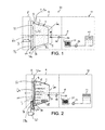
- Fig. 1
- is a schematic drawing of a preferred embodiment of a beverage preparation device according to the present invention in a capsule insert position.
- Fig. 2
- is a schematic drawing of the beverage preparation device of
figure 1 in a capsule enclosing and extracting position. - Fig. 3a
- is a perspective view of a preferred embodiment of the opening means according to the invention.
- Fig. 3b
- is a sectional side view of the opening means according to
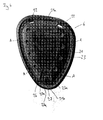
figure 3a . - Fig. 4
- is a perspective view of a preferred embodiment of the wall member of the capsule according to the present invention.
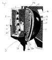
- Fig. 5
- is a perspective side view of a preferred embodiment of the capsule and the opening means according to the present invention interacting with each other.
- Fig. 6
- is an enlarged perspective side view of the embodiment of the capsule and the opening means according to
figure 5 . - First of all, the general brewing principle of the invention will be explained in relation to
figures 1 and 2 and a preferred embodiment of the capsule according to the invention. - A
capsule system 30 is provided that comprises a capsule 1 and abeverage preparation device 10. For simplicity, the beverage preparation device is only schematically depicted and may, in reality, comprise additional technical features within the normal knowledge of the person skilled in the art. - The capsule 1 comprises an ingredients compartment 2 containing beverage ingredients such as leaf tea and the like. The ingredients compartment is demarcated by a cup-shaped housing 32 and a
wall member 4. Thereby, the capsule 1 comprises an inlet face 6a which is constituted by a portion of the cup-shaped housing 32. Moreover, the capsule comprises anoutlet face 6b which comprises thewall member 4 and a cover 11 overlaying the wall member - Preferably, a
filtering wall 33 is fixedly attached to peripheral inner step 34 of the housing 32, thereby enclosing the beverage ingredients within the cup-shaped housing. The ingredients compartment is preferably impermeable to gas and light. - The housing 32 may encompass different cross sections such as a circular, ellipsoid, square, rectangular or polygonal section that determine as a matter of fact the general profile of the
filtering wall 33. The ingredients compartment is sized to accommodate a dose of leaf beverage ingredient of typically about between 1 to 10 grams, preferably 2 to 5 grams. The dose of leaf ingredient may depend on the final volume of beverage to produce. For an individual cup of tea, a typical dose can be of about 2 grams whereas for a tea pot, a typical dose can be of about 8 to 10 grams. As clearly apparent infigure 1 , the capsule is positioned relative to the brewing device so that thewall member 4 and thefiltering wall 33 extend substantially vertical and from substantially the bottom of the enclosure. For this, the capsule is preferably positioned in a 'vertical' arrangement in thebeverage preparation device 10. Thus, the cup-shaped housing 32 is preferably oriented with its inlet and outlet faces 6a, 6b being orientated essentially vertically. - At the
outlet face 6b, thewall member 4 preferably comprises at least oneoverflow aperture 22. The at least oneoverflow aperture 22 is in fluid communication with the ingredients compartment 2. - The capsule 1 is closed by the cover 11 that hermetically closes the enclosure of the capsule 1 and thus, the ingredients compartment 2 and the
wall member 4. The cover 11 is preferably attached to an outercircumferential rim portion 21 of the housing 32, for example a flange as illustrated inFigures 5 and6 . Thereby, achannel 23 is formed at the outlet face of the capsule 1 which is designed to guide a fluid downward from the at least oneoverflow aperture 22. Thesecond rim portion 21b is preferably essentially opposite to the first rim portion 21a at which the aperture of the cover member is provided. Accordingly, liquid which exits the ingredients compartment by means ofaperture 22 is guided essentially parallel to theoutlet face 6b of the capsule 1 downward. - Both the cover 11 and the housing 32 can be made of oxygen barrier materials and the enclosure can be substantially free of oxygen so that the freshness of the beverage ingredients can be preserved during an extended period of time. The sealing wall is preferably a flexible and puncturable sealing cover, e.g. a monolayer or a multi-layer cover, typically, laminates of PET/Aluminium/PP, PE/EVOH/PP, PET/Metallised/PP, Aluminum/PP, paper.
- The enclosure may contain flushed gas such as N2, N2O or CO2.
- The housing can be manufactured industrially at lower cost by plastic thermoforming or aluminium deep drawing. This shape with smoother corners also favours the removal of the handling engagement members and so ejection of the capsule.
- The beverage
preparation brewing device 10 preferably comprises two enclosingmembers members members members members figure 1 to a capsule enclosing position as shown infigure 2 . - These enclosing
members - The beverage preparation device comprises an external or internal liquid supply 11, such as a water tank, a
water pump 12, heating means 37, e.g. a thermoblock, and a hotwater injection line 35 that is managed through the enclosingmember 9. The beverage preparation device may also comprise a controller and a user interface board (not shown) to manage the beverage preparation cycles as known in the art. - A
backpressure valve 36 may be provided at the entry side of an injection member 39 (such as a needle(s) or blade(s) and a water inlet) in the capsule. - The brewing device further comprises opening means 3 which are designed to shear the cover 11 by interaction with the
wall member 4 of the capsule. The opening means 3 are preferably connected to one of the enclosingmembers 8. Thereby, the opening means 3 are configured to open the cover 11 of the capsule by creating anoutlet aperture 38. Preferably, the opening means 3 are designed to shear the cover 11 by interacting with a dedicated shearing member 27 (seefigure 4 ) of thewall member 4. - The opening of the cover 11 and thus, the engagement of the opening means 3 and the
wall member 4 preferably takes place when the enclosingmembers device 10 are brought from their capsule insertion position as shown infigure 1 into their capsule enclosing position as shown infigure 2 . The movement of the enclosingmembers - In the brewing operation as shown in
figure 2 , thewall member 4 constitutes an overflow wall with theaperture 22 acting as overflow aperture. Thereby, the capsule is preferably orientated in the device such that theoverflow aperture 22 is above a median horizontal plane P of the capsule. - As also apparent in
figure 2 , thefiltering wall 33 and thewall member 4 are spaced apart a short distance sufficient to create an interstitial space 's' that is supposed, without being bound by theory, to work as a sort of 'siphon' that can promote the upward motion of the denser beverage portion that is predominantly localized in the bottom of the enclosure. The interstitial space can range of from 0.1 to 8 mm, preferably, about 0.5 to 3 mm. - In relation to
figure 2 , the method of the invention works as follows. The capsule is inserted in the beverage preparation device and thecapsule enclosing members outlet face 6a, 6b being substantially vertically oriented. Thereby, the opening means 3 create anoutlet aperture 38 in the cover 11 sealed to thecapsule rim 21. On the opposite side of the capsule, thefluid injection member 39 is introduced in the capsule's ingredients compartment 2. Hot water is thus injected into the capsule at relatively low pressure, preferably, at a pressure not exceeding 0.2 bar. Hot water slowly fills the capsule and submerges the beverage ingredients in the enclosure. The brewed beverage is filtered through thefiltering wall 33. A denser portion 40 of the beverage may tend to settle in the bottom of the enclosure; which portion is also filtered through thefiltering wall 33 since it is properly placed adjacent this portion. The denser beverage is evacuated through the interstitial space 's' as caused by the variation of pressure between the lower part of the space and the upper part of said space therefore acting similarly to a 'siphon'. The rest of the beverage is also filtered also by passing through thefiltering wall 33 at different vertical levels up to the upper level of the fluid in the enclosure and is evacuated to theoverflow aperture 22. - It should be noted that the
overflow aperture 22 should preferably be placed above the median of the total height of the ingredients compartment and even preferably be placed above the 4/5 of the total height thereof; thus ensuring a more complete submergence of the beverage ingredients and a slower evacuation of the beverage from the compartment which favors a better infusion process. The 'total height' of the compartment is meant to be the total distance separating the lowermost point of the compartment to the uppermost point thereof when the capsule is positioned in the beverage device ready for the brewing operation. In a possible mode, thefiltering wall 33 can be substantially equal to the total height of the compartment. - The
outlet opening 38 created in the cover 11 is preferably positioned downwardly theaperture 22. Hence, liquid being ejected from theoverflow aperture 22 is guided essentially parallel to theoutlet face 6b of the capsule before reaching the outlet opening 38 of the capsule. For the guidance of the beverage betweenaperture 22 andoutlet opening 38, at least one guiding channel 23 (seefigure 3 ) is preferably arranged at theoutlet face 6b of the capsule. - After ejecting from the capsule 1, the beverage is preferably guided by guiding means 13 (see
figure 3a, 3b ) towards areceptacle 20 such as for example a cup or a mug. - A preferred embodiment of the opening means according to the present invention will now be described with reference to
figures 3a and 3b , wherein 3a is perspective view of the opening means andfigure 3b is a sectional side view of the opening means. - The opening means are preferably made of plastic material by means of injection moulding. As can be seen in
figure 3a , the opening means 3 preferably compriseconnection members 43, for example pins, which are designed to enable a connection between the opening means 3 and an enclosingmember 8 of the device 10 (cf.figure 5 ). - The opening means 3 comprise an opening member 7 protruding from an essentially vertically arranged
base portion 12 of the opening means 3. The opening member 7 is preferably a hook-shaped member which is arranged slanted at an angle α with respect to thebase 12 of the opening means 3. The angle α preferably lies between 40 and 65°. - The hook-like member 7 comprises a slanted wall portion 7a and two side wall portions 7c which enclose a hopper-shaped recess 14. A longitudinal edge of the slanted wall portion 7a constitutes the
cutting edge 8 of the hook-like member 7. Thereby, thelongitudinal edge portion 8 is preferably arranged essentially horizontal within thedevice 10. Optionally, thelongitudinal cutting edge 8 may comprise acentral recession 8a to avoid that the opening member 7 bumps against the edge 27a (seefigure 4 ) of the shearing member. Thelongitudinal edge 8 is preferably between 1 and 25 mm. - Accordingly, a large opening in the cover is provided when the hook-like member 7 is engaging with the cover 11 of the capsule.
- When the opening member 7 is made to cut the cover 11 (cf.
figure 2 ), a portion of the cover 11 is deflected by the upper surface 7b of the hook-like member 7. Thereby, the upper surface 7b may be curved or gradually stepped as indicated infigure 3b . - The base of the opening means 3 is preferably disposed between two vertically arranged
side walls 12a, thereby constituting anopen fluid channel 13 for guiding the liquid provided to the hopper-shaped collecting member 14 to areceptacle 20 positioned underneath the opening member 3 (cf.figure 2 ). - Furthermore, from the
base portion 12 respectively from theopen channel 13, an essentially vertically arrangedridge 15 is protruding. Thereby, anupper portion 15a of theridge 15 preferably protrudes from the center of the hopper-shaped collecting member 14. From there, the protrudingridge 15 extends within the guiding means 13 towards a lower end portion 15b thereof, said lower end portion 15b is designed to act as a tearing edge of the guiding means 13. Accordingly any beverage ejected through the outlet opening 38 of the capsule 1 is collected by the recessed collecting member 14 and is then guided by means of the guiding means 13 towards areceptacle 20. Thereby, any remaining drops of the beverage are guided by means of gravity towards a lower end portion of theridge 15 at which tip the drops are torn off such that essentially no beverage remains sticking at/or within the guiding means. Hence, cross contamination can be effectively minimized. - Moreover, due to the channel or groove-like design of the guiding means 13, the provision of common guiding means such as for example a tube can be prevented and thus, the remaining of liquid staying inside the guiding means can be prevented.
-
Figure 4 shows a preferred embodiment of thewall member 4 according to the present invention which is preferably connected to the capsule housing 32. Thewall member 4 is preferably made of plastic material by injection molding. As shown infigure 4 , the wall member comprises a preformedchannel 23 arranged at the circumference of thewall member 4. Thereby, the preformedchannel 23 is in fluid connection with at least oneaperture 22 being in fluid connection with the ingredients compartment 2 (c.f.figure 1 and 2 ). Preferably, as shown infigure 4 , twoapertures 22 are provided at an upper portion of thewall member 4. - As indicated by arrows A, the
pre-formed channel 23 is designed to guide beverage which is ejected from theapertures 22 at an upper portion of thewall member 4 towards a lower portion of the wall member. The preformedchannel 23 preferably comprises no sharp corners or edges such that the liquid can be smoothly guided fromaperture 22 towards the lower portion. - In order to provide sufficient space for the beverage to be guided by the interstitial space between the cover 11 and the
wall member 4, i.e. by the preformedchannel 23, the interstitial space 't' is preferably between 1 and 10 mm. (cf.figure 2 ). - At its
lower portion 21b, thewall member 4 comprises a recess 26 which is designed to accommodate the hook-shaped opening member 7 of the opening means 3 during an engagement of the opening means 3 and the capsule 1. - The recess 26 is in fluid connection with the preformed
channel 23. - In addition, a shearing
member 27 is provided within the recess 26 which is designed to interact with thelongitudinal cutting edge 8 of the opening member 7. The shearingmember 27 holds up the cover 11 when the opening member (7) comes into contact with it which increases the tension on the cover 11 and facilitates its shearing. Thereby, the shearingmember 27 is preferably wedge-shaped, having a linear shearing edge which is preferably arranged in parallel to thelongitudinal cutting edge 8 of the opening member 7 during interaction of the opening means 3 and the capsule 1. - Furthermore, the
wall member 4 may comprise additional apertures respectively holes 41 which are preferably arranged at a center portion of thewall member 4. Said recesses or holes 41 are designed to enable an interaction of thewall member 4 with dedicated decoding means (not shown) of the device in order to determine the particular ingredients provided within thecapsule 4. Thus, the nature of the ingredients contained within the capsule can be decoded by means of dedicated pins which are provided at the enclosingmember 8 to enable the identification of the type of capsule to be extracted. Accordingly, for example the brewing parameters of the capsule may be altered by the device as explained inEP 1 950 150 . - It should be noted that the
apertures 22 are preferably preformed apertures which do not need to be pierced by any opening means. However, theapertures 22 may be equipped with filter elements in order to prevent any leaf tea to leave the ingredients compartment 2. -
Figure 5 is a perspective side view of a preferred embodiment of the capsule and the opening means interacting with each other. - As shown, the opening means 3 are connected to the enclosing
member 8 by means of the connection pins 43. It should be noted that the enclosingmembers figure 1 ) and a second capsule enclosing position (cf.figure 2 ) by means of a linear movement. However, the first andsecond enclosing members - As the enclosing
member 8 is approached to theoutlet face 6b of the capsule, at which thewall member 4 is provided, the hook-shaped opening member 7 punctures the cover 11 sealed to thewall member 4 at theoutlet face 6b. Please note that the cover 11 is not depicted infigure 5 . Thereby, preferably gas is enclosed by the cover 11 such that the surface of the cover puffs out at the outlet face of the capsule and thus, puncturing respectively cutting of the cover 11 by means of the opening member 7 is facilitated. - The opening of the cover 11 is particularly obtained by shearing the cover between the shearing
member 27 abutting on the inner surface of the cover 11 and thelongitudinal cutting edge 8 of the opening member 7. Thereby, a linear shearing edge 27a is preferably interacting with thelongitudinal cutting edge 8 and/or arecess 8a provided preferably at a center portion of thelongitudinal cutting edge 8 such that cover 11 is sheared there between. Thereby, a portion of the cover 11 is inwardly deflected towards the recess 26 of thewall member 4 of the capsule in which the hook-shaped member 7 is accommodated. - The enclosing
member 8 may be equipped with identification means 42 which comprise recesses 42a in which pins (not shown) are guided which enable an identification of the inserted capsule 1 by means of interacting with holes or recesses 41 provided at awall member 4 of the capsule. Thereby, the cover 11 sealed to thewall member 4 may be punctured at a central portion thereof for enabling identification. -
Figure 6 is an enlarged perspective view of the embodiment of the capsule and the opening means according tofigure 5 . - As shown in
figure 6 , the hook-shaped opening member 7 is preferably fully received in the recess 26 of thewall member 4. Please note that again the cover 11 is not shown infigure 6 . - According to that, the portion of the cover 11 is fully deflected towards the center of the capsule 1 due to the slanted surface 7a of the hook-shaped member 7. Hence, an outlet opening 38 (cf.
figure 2 ) is created which is large enough to enable an ejection of the liquid from the capsule without a pressure rise within the capsule. In particular, due to the deflection of the sheared cover 11, no parts of the cover obstruct the createdoutlet opening 38. Moreover, since the hook-shaped member 7a is fully received in the dedicated recess 26 of thewall member 4, the opening means 3 do not obstruct the created outlet opening 38 as well. - As indicated by arrows A, beverage is ejected from the
apertures 22 and guided by means of the preformedchannel 23 at arim portion 21 of the capsule to the createdoutlet opening 38. Thereby, the beverage is collected by the hopper-shaped collecting recess 14 of the hook-shaped member 7 and is thus guided by means of the guiding means 13 towards areceptacle 20. Thereby, as the hopper-shaped collecting recess is formed at abase portion 12 of the opening means 3, and due to the fact that the beverage approaches the hook-shaped member 7 from below, the opening means 3 and in particular the opening member 7 does not obstruct the createdoutlet opening 38 and thus, the creation of pressure within the capsule can be effectively prevented during brewing. Hence, the ejection characteristics of the capsule are significantly enhanced. - Although the present invention has been described with reference to preferred embodiments thereof, many modifications and alternations may be made by a person having ordinary skill in the art without departing from the scope of this invention which is defined by the appended claims.
Claims (13)
- A system comprising a beverage preparation device (10) and a capsule (1) for preparing a beverage from a food substance contained in a compartment (2) of the capsule by injection of a liquid into the capsule, the beverage preparation device (10) having
opening means (3) which are designed to interact with a wall member (4) provided at an outlet face (6b) of the capsule (1),
wherein the opening means (3) comprise an opening member (7) having a hook-like shape designed to shear and move away at least a portion of a cover (11) sealed to the outlet face (6b) of the capsule. - A system according to claim 1,
wherein the opening member (7) is a hook-like member which is designed to deflect at least a portion of the cover (11) towards an upper face (12a) of the hook-like member. - A system according to claim 1 or 2,
wherein the hook-like member (7) is curved or slanted with respect to the vertically arranged base (12) of the opening means - A system according to any of the preceding claims,
wherein the opening means (3) further comprise integrally formed guiding means (13) designed to redirect a beverage from the capsule (1) to a receptacle (20). - A system according to claim 4,
wherein the guiding means (13) comprise a recessed collecting member (14) situated at the base (12) of the opening means (3). - A system according to claim 4 or 5,
wherein the guiding means (13) further comprise a essentially vertical ridge (15) protruding from the base (12) of the opening means (3). - A system according to claim 6,
wherein a tearing edge (15b) of the guiding means (13) is constituted by means of a tip of the vertical ridge(15). - A system according to any of the preceding claims,
wherein gas under pressure is enclosed by the cover (11) sealed to the outlet face (6b) of the capsule (1). - A capsule (1) for preparing a beverage in a beverage machine comprising :- an ingredients compartment (2),- a wall member (4) provided at an outlet face (6b) of the capsule (1), the wall member comprising at least one overflow aperture (22) in fluid communication with the ingredients compartment (2),- a cover (11) sealed to the outlet face (6b) and wherein the wall member (4) is provided with at least one preformed channel (23) at the outlet face of the capsule and designed to guide a fluid from the at least one overflow aperture (22) to at leat one recess (26) being designed to receive dedicated opening means (3) of a beverage preparation device.
- A capsule according to claim 9,
wherein the wall member (4) comprises a shearing member (27) abutting on the cover (11) and designed to interact with the dedicated opening means (3) such that at least a portion of the cover (11) is sheared between the shearing member (27) and the opening means (3). - A capsule according to claim 9,
wherein the cover (11) is a mono-layer or a multi-layer cover comprising at least aluminium. - A capsule (1) for preparing a beverage in a beverage machine comprising :- an ingredients compartment (2),- a wall member (4) provided at an outlet face (6b) of the capsule (1),- a cover (11) sealed to the outlet face (6b),
the wall member (4) being provided with functional hollows (41, 23) and/or bulges facing the outlet face (6b), and
gas being enclosed by the cover (11) sealed to the outlet face (6b) of the capsule (1),
wherein the pressure of the gas is sufficient to puff out the cover. - A capsule according to claim 12, wherein the wall member (4) is provided with at least one preformed channel (23) at the outlet face of the capsule and designed to guide a fluid from at least one overflow aperture (22) of the wall member in fluid communication with the ingredients compartment to at least one recess (26) being designed to receive dedicated opening means (3) of a beverage preparation device (10).
Priority Applications (14)
| Application Number | Priority Date | Filing Date | Title |
|---|---|---|---|
| EP09162921.2A EP2263501B1 (en) | 2009-06-17 | 2009-06-17 | Opening means for a capsule-based beverage preparation device |
| DK09162921.2T DK2263501T3 (en) | 2009-06-17 | 2009-06-17 | Means for opening a capsule-based device for preparing a beverage |
| ES09162921.2T ES2556265T3 (en) | 2009-06-17 | 2009-06-17 | Opening means for a capsule-based beverage preparation device |
| CA2763394A CA2763394C (en) | 2009-06-17 | 2010-06-17 | Opening means for a capsule-based beverage preparation device |
| PCT/EP2010/058506 WO2010146101A1 (en) | 2009-06-17 | 2010-06-17 | Opening means for a capsule-based beverage preparation device |
| US13/375,390 US8820216B2 (en) | 2009-06-17 | 2010-06-17 | Opening means for a capsule-based beverage preparation device |
| JP2012515485A JP5528548B2 (en) | 2009-06-17 | 2010-06-17 | Opening means for a capsule-type beverage preparation device |
| KR1020117030214A KR101755208B1 (en) | 2009-06-17 | 2010-06-17 | Opening means for a capsule-based beverage preparation device |
| AU2010261809A AU2010261809B2 (en) | 2009-06-17 | 2010-06-17 | Opening means for a capsule-based beverage preparation device |
| RU2012101415/12A RU2520065C2 (en) | 2009-06-17 | 2010-06-17 | Means for opening beverage preparation capsule device |
| SG2011085735A SG176580A1 (en) | 2009-06-17 | 2010-06-17 | Opening means for a capsule-based beverage preparation device |
| BRPI1011949A BRPI1011949A2 (en) | 2009-06-17 | 2010-06-17 | "opening means for a capsule-based beverage preparation device" |
| CN201080026312.XA CN102802475B (en) | 2009-06-17 | 2010-06-17 | Opening means for a capsule-based beverage preparation device |
| ZA2012/00324A ZA201200324B (en) | 2009-06-17 | 2012-01-16 | Opening means for as a capsule-based beverage preparation device |
Applications Claiming Priority (1)
| Application Number | Priority Date | Filing Date | Title |
|---|---|---|---|
| EP09162921.2A EP2263501B1 (en) | 2009-06-17 | 2009-06-17 | Opening means for a capsule-based beverage preparation device |
Publications (2)
| Publication Number | Publication Date |
|---|---|
| EP2263501A1 true EP2263501A1 (en) | 2010-12-22 |
| EP2263501B1 EP2263501B1 (en) | 2015-11-25 |
Family
ID=41611128
Family Applications (1)
| Application Number | Title | Priority Date | Filing Date |
|---|---|---|---|
| EP09162921.2A Active EP2263501B1 (en) | 2009-06-17 | 2009-06-17 | Opening means for a capsule-based beverage preparation device |
Country Status (14)
| Country | Link |
|---|---|
| US (1) | US8820216B2 (en) |
| EP (1) | EP2263501B1 (en) |
| JP (1) | JP5528548B2 (en) |
| KR (1) | KR101755208B1 (en) |
| CN (1) | CN102802475B (en) |
| AU (1) | AU2010261809B2 (en) |
| BR (1) | BRPI1011949A2 (en) |
| CA (1) | CA2763394C (en) |
| DK (1) | DK2263501T3 (en) |
| ES (1) | ES2556265T3 (en) |
| RU (1) | RU2520065C2 (en) |
| SG (1) | SG176580A1 (en) |
| WO (1) | WO2010146101A1 (en) |
| ZA (1) | ZA201200324B (en) |
Cited By (10)
| Publication number | Priority date | Publication date | Assignee | Title |
|---|---|---|---|---|
| CN102166096A (en) * | 2011-04-10 | 2011-08-31 | 九阳股份有限公司 | Beverage preparation method |
| WO2014006052A3 (en) * | 2012-07-06 | 2014-05-15 | Unilever Plc | Capsule, method and device for brewing a beverage |
| USD732387S1 (en) | 2013-03-21 | 2015-06-23 | Conopco, Inc. | Capsule |
| USD732386S1 (en) | 2013-03-21 | 2015-06-23 | Conopco, Inc. | Capsule |
| US9737166B2 (en) | 2012-04-11 | 2017-08-22 | Koninklijke Philips N.V. | Beverage producing system and capsule |
| US9783361B2 (en) | 2013-03-14 | 2017-10-10 | Starbucks Corporation | Stretchable beverage cartridges and methods |
| US9877495B2 (en) | 2015-01-09 | 2018-01-30 | Starbucks Corporation | Method of making a sweetened soluble beverage product |
| US10004353B2 (en) | 2013-03-21 | 2018-06-26 | Conopco, Inc. | Method, device and capsule for brewing a beverage |
| US10442610B2 (en) | 2014-03-11 | 2019-10-15 | Starbucks Corporation | Pod-based restrictors and methods |
| US12616327B2 (en) | 2023-02-20 | 2026-05-05 | Sensio Inc. | Beverage brewing systems and methods |
Families Citing this family (33)
| Publication number | Priority date | Publication date | Assignee | Title |
|---|---|---|---|---|
| GB201110848D0 (en) | 2011-06-24 | 2011-08-10 | Mars Inc | Beverage preparation apparatus and method and beverage capsules for use therein |
| US10080459B2 (en) | 2011-11-09 | 2018-09-25 | La Vit Technology Llc | Capsule-based system for preparing and dispensing a beverage |
| US10034570B2 (en) | 2011-11-09 | 2018-07-31 | LaVit Technology LLC | Capsule based system for preparing and dispensing a beverage |
| AU2013329854B2 (en) * | 2012-10-09 | 2017-11-16 | Nestec S.A. | Beverage machine |
| CN104968244B (en) * | 2012-12-07 | 2018-09-18 | 雀巢产品技术援助有限公司 | Beverage production device with improved container injection device |
| US9859761B2 (en) * | 2013-02-12 | 2018-01-02 | Asmo Co., Ltd. | Rotor and motor |
| ITBO20130315A1 (en) * | 2013-06-21 | 2014-12-22 | Ima Ind Srl | UNITS AND FILLING METHOD OF CONTAINMENT ELEMENTS FOR DISPOSABLE OR INFUSION CAPSULES FOR DRINKS |
| US20160137403A1 (en) * | 2013-06-25 | 2016-05-19 | Nestec S.A. | Cover for a beverage capsule |
| BE1021777B1 (en) * | 2013-06-25 | 2016-01-18 | Tconcept Company S.P.R.L. | DEVICE FOR PREPARING INFUTED BEVERAGES COMPRISING A POSITIONING MEANS FOR THE CAPSULE |
| US9320382B2 (en) | 2013-07-15 | 2016-04-26 | La Vit Technology Llc | Capsule based system for preparing and dispensing a beverage |
| US10398253B2 (en) | 2013-09-03 | 2019-09-03 | Societe Des Produits Nestle S.A. | Beverage production machine using capsules |
| AU2014353150A1 (en) | 2013-11-19 | 2016-07-07 | Vanderbilt University | Substituted imidazopyridine and triazolopyridine compounds as negative allosteric modulators of mGluR5 |
| US9533982B2 (en) | 2014-03-20 | 2017-01-03 | Vanderbilt University | Substituted bicyclic heteroaryl carboxamide analogs as mGluR5 negative allosteric modulators |
| BR112017000233A2 (en) | 2014-07-08 | 2018-01-16 | Gima Spa | filling unit for filling single-use capsule container elements and method for filling single-use capsule container elements |
| JP2017524613A (en) * | 2014-07-08 | 2017-08-31 | ジーマ ソチエタ ペル アツィオニGima S.P.A | Unit and method for filling container elements of disposable capsules for extraction or infusion beverages |
| CN104433814B (en) * | 2014-10-22 | 2017-04-12 | 宁波全景电器技术有限公司 | Beverage brewing equipment allowing beverage bag to be removed easily |
| PT3143910T (en) * | 2015-09-17 | 2018-11-05 | Mocoffee Europe Unipessoal Lda | Apparatus for producing a beverage from a capsule |
| US20170252996A1 (en) * | 2016-03-03 | 2017-09-07 | Juicero, Inc. | Juicer cartridge with secondary flow channel |
| US11224306B2 (en) | 2016-05-18 | 2022-01-18 | Lg Electronics Inc. | Beverage-making apparatus |
| CN107400585B (en) * | 2016-05-18 | 2021-07-30 | Lg电子株式会社 | Beer brewing device |
| CN107400583B (en) | 2016-05-18 | 2021-07-13 | Lg电子株式会社 | Beer brewing bag and beer brewing device having the same |
| US11208621B2 (en) * | 2016-05-18 | 2021-12-28 | Lg Electronics Inc. | Beverage-making apparatus |
| CN107400586B (en) | 2016-05-18 | 2021-05-28 | Lg电子株式会社 | Beer brewing device |
| CN107400588B (en) | 2016-05-18 | 2021-08-03 | Lg电子株式会社 | Beer brewing device |
| EP3490908B1 (en) | 2016-07-26 | 2020-10-28 | Société des Produits Nestlé S.A. | Capsule and beverage production system |
| KR102422867B1 (en) | 2016-07-26 | 2022-07-19 | 소시에떼 데 프로듀이 네슬레 소시에떼아노님 | Capsules for making beverages |
| JP7008038B2 (en) | 2016-07-26 | 2022-01-25 | ソシエテ・デ・プロデュイ・ネスレ・エス・アー | Capsule and beverage generation system |
| TW201808183A (en) * | 2016-08-16 | 2018-03-16 | 耐斯泰克公司 | Fitment assembly for food or beverage containers |
| EP3537891B1 (en) | 2016-11-09 | 2024-09-11 | PepsiCo, Inc. | Carbonated beverage makers, methods, and systems |
| US12016483B2 (en) * | 2018-03-14 | 2024-06-25 | Societe Des Produits Nestle S.A. | Beverage machine with a partly opening dispensing face |
| CN119012947A (en) | 2022-03-07 | 2024-11-22 | 雀巢产品有限公司 | Beverage preparation system |
| WO2023170082A1 (en) | 2022-03-07 | 2023-09-14 | Société des Produits Nestlé S.A. | Beverage preparation machine |
| CN118843408A (en) | 2022-03-07 | 2024-10-25 | 雀巢产品有限公司 | Beverage preparation machine |
Citations (11)
| Publication number | Priority date | Publication date | Assignee | Title |
|---|---|---|---|---|
| GB1397116A (en) | 1971-06-11 | 1975-06-11 | Jacobs Joh & Co | Preparation of a filtered beverage |
| EP0512468A1 (en) | 1991-05-10 | 1992-11-11 | Societe Des Produits Nestle S.A. | Closed cartridge for making a beverage |
| EP0512470A1 (en) | 1991-05-08 | 1992-11-11 | Societe Des Produits Nestle S.A. | Method of producing beverages using sealed cartridges and apparatus for carrying out this method |
| US20020148356A1 (en) | 2001-04-11 | 2002-10-17 | Lazaris Nicholas G. | Beverage filter cartridge holder |
| US20020148357A1 (en) | 2001-04-11 | 2002-10-17 | Lazaris Nicholas G. | Beverage filter cartridge holder |
| WO2003059778A2 (en) * | 2002-01-16 | 2003-07-24 | Societe Des Produits Nestle S.A. | Closed capsule with opening mean |
| WO2007042414A1 (en) | 2005-10-14 | 2007-04-19 | Nestec S.A. | Capsule for the preparation of a beverage |
| EP1882432A1 (en) * | 2006-07-24 | 2008-01-30 | Nestec S.A. | Method for delivering faster a short coffee extract from capsule |
| EP1894853A1 (en) * | 2006-08-30 | 2008-03-05 | Nestec S.A. | Capsule for the preparation of a beverage |
| EP1950150A1 (en) | 2007-01-24 | 2008-07-30 | Nestec S.A. | Identification of beverage ingredient containing capsules |
| US20090007793A1 (en) * | 2007-07-02 | 2009-01-08 | Appliance Development Corporation | Infusible material capsule for brewing a beverage |
Family Cites Families (14)
| Publication number | Priority date | Publication date | Assignee | Title |
|---|---|---|---|---|
| US3260190A (en) * | 1963-09-23 | 1966-07-12 | David J Levinson | Equipment adaptable to brewing coffee in the original sealed container |
| US3470812A (en) * | 1968-03-18 | 1969-10-07 | David J Levinson | Coffee brewing head |
| US5899137A (en) * | 1997-01-13 | 1999-05-04 | Weber Aircraft, Inc. | Beverage making apparatus with can piercer |
| EP1203554A1 (en) * | 2000-11-03 | 2002-05-08 | Societe Des Produits Nestle S.A. | Device for extracting food material stored in a reloading cartridge |
| GB2382976B (en) * | 2001-12-11 | 2005-07-20 | Mars Inc | Beverage brewing method and apparatus |
| DE20221780U1 (en) * | 2002-03-14 | 2007-10-18 | Caffita System S.P.A., Gaggio Montano | Portion capsule with a particulate extractable by water substance for the preparation of a beverage |
| DE102004002004A1 (en) * | 2004-01-14 | 2005-08-11 | Schifferle, René | Coffee machine for brewing coffee powder packaged in a capsule |
| MY138658A (en) * | 2004-02-20 | 2009-07-31 | Nestec Sa | System for dispensing short and long coffee beverages |
| ITGE20040020A1 (en) * | 2004-03-12 | 2004-06-12 | Termozeta Spa | Pre-packaged filler for espresso coffee machines, and dispenser group suitable for the use of this filler. |
| DE102004056224A1 (en) * | 2004-11-19 | 2006-05-24 | Tchibo Gmbh | System with a coffee maker and a portion capsule |
| ES2298947T3 (en) * | 2005-10-14 | 2008-05-16 | Nestec S.A. | METHOD FOR THE PREPARATION OF A DRINK FROM A CAPSULE. |
| DE602006006675D1 (en) * | 2006-08-30 | 2009-06-18 | Nestec Sa | Capsule for making beverages |
| EP1894854B1 (en) * | 2006-08-30 | 2009-11-18 | Nestec S.A. | Capsule for brewing a breverage |
| ITMO20070241A1 (en) * | 2007-07-20 | 2009-01-21 | Saeco Ipr Ltd | DEVICE FOR DRILLING PORTIONED CAPS |
-
2009
- 2009-06-17 ES ES09162921.2T patent/ES2556265T3/en active Active
- 2009-06-17 DK DK09162921.2T patent/DK2263501T3/en active
- 2009-06-17 EP EP09162921.2A patent/EP2263501B1/en active Active
-
2010
- 2010-06-17 JP JP2012515485A patent/JP5528548B2/en not_active Expired - Fee Related
- 2010-06-17 KR KR1020117030214A patent/KR101755208B1/en not_active Expired - Fee Related
- 2010-06-17 BR BRPI1011949A patent/BRPI1011949A2/en not_active IP Right Cessation
- 2010-06-17 US US13/375,390 patent/US8820216B2/en active Active
- 2010-06-17 AU AU2010261809A patent/AU2010261809B2/en not_active Ceased
- 2010-06-17 RU RU2012101415/12A patent/RU2520065C2/en not_active IP Right Cessation
- 2010-06-17 CN CN201080026312.XA patent/CN102802475B/en not_active Expired - Fee Related
- 2010-06-17 CA CA2763394A patent/CA2763394C/en not_active Expired - Fee Related
- 2010-06-17 SG SG2011085735A patent/SG176580A1/en unknown
- 2010-06-17 WO PCT/EP2010/058506 patent/WO2010146101A1/en not_active Ceased
-
2012
- 2012-01-16 ZA ZA2012/00324A patent/ZA201200324B/en unknown
Patent Citations (11)
| Publication number | Priority date | Publication date | Assignee | Title |
|---|---|---|---|---|
| GB1397116A (en) | 1971-06-11 | 1975-06-11 | Jacobs Joh & Co | Preparation of a filtered beverage |
| EP0512470A1 (en) | 1991-05-08 | 1992-11-11 | Societe Des Produits Nestle S.A. | Method of producing beverages using sealed cartridges and apparatus for carrying out this method |
| EP0512468A1 (en) | 1991-05-10 | 1992-11-11 | Societe Des Produits Nestle S.A. | Closed cartridge for making a beverage |
| US20020148356A1 (en) | 2001-04-11 | 2002-10-17 | Lazaris Nicholas G. | Beverage filter cartridge holder |
| US20020148357A1 (en) | 2001-04-11 | 2002-10-17 | Lazaris Nicholas G. | Beverage filter cartridge holder |
| WO2003059778A2 (en) * | 2002-01-16 | 2003-07-24 | Societe Des Produits Nestle S.A. | Closed capsule with opening mean |
| WO2007042414A1 (en) | 2005-10-14 | 2007-04-19 | Nestec S.A. | Capsule for the preparation of a beverage |
| EP1882432A1 (en) * | 2006-07-24 | 2008-01-30 | Nestec S.A. | Method for delivering faster a short coffee extract from capsule |
| EP1894853A1 (en) * | 2006-08-30 | 2008-03-05 | Nestec S.A. | Capsule for the preparation of a beverage |
| EP1950150A1 (en) | 2007-01-24 | 2008-07-30 | Nestec S.A. | Identification of beverage ingredient containing capsules |
| US20090007793A1 (en) * | 2007-07-02 | 2009-01-08 | Appliance Development Corporation | Infusible material capsule for brewing a beverage |
Cited By (19)
| Publication number | Priority date | Publication date | Assignee | Title |
|---|---|---|---|---|
| CN102166096B (en) * | 2011-04-10 | 2012-11-21 | 九阳股份有限公司 | Beverage preparation method |
| CN102166096A (en) * | 2011-04-10 | 2011-08-31 | 九阳股份有限公司 | Beverage preparation method |
| US9737166B2 (en) | 2012-04-11 | 2017-08-22 | Koninklijke Philips N.V. | Beverage producing system and capsule |
| US10143214B2 (en) | 2012-07-06 | 2018-12-04 | Conopco, Inc. | Method and device for brewing a beverage |
| WO2014006052A3 (en) * | 2012-07-06 | 2014-05-15 | Unilever Plc | Capsule, method and device for brewing a beverage |
| US11191286B2 (en) | 2012-07-06 | 2021-12-07 | Conopco, Inc. | Capsule, method and device for brewing a beverage |
| AU2013285526B2 (en) * | 2012-07-06 | 2016-11-10 | Ekaterra Research and Development UK Limited | Capsule, method and device for brewing a beverage |
| CN110436060B (en) * | 2012-07-06 | 2021-03-19 | 荷兰联合利华有限公司 | Capsule, method and device for brewing a beverage |
| CN110436060A (en) * | 2012-07-06 | 2019-11-12 | 荷兰联合利华有限公司 | Pocket, method and apparatus for soaking beverage |
| US10004248B2 (en) | 2012-07-06 | 2018-06-26 | Conopco, Inc. | Package recognition system |
| EA031158B1 (en) * | 2012-07-06 | 2018-11-30 | Юнилевер Н.В. | Capsule, method and device for brewing a beverage |
| US9783361B2 (en) | 2013-03-14 | 2017-10-10 | Starbucks Corporation | Stretchable beverage cartridges and methods |
| USD732386S1 (en) | 2013-03-21 | 2015-06-23 | Conopco, Inc. | Capsule |
| US10004353B2 (en) | 2013-03-21 | 2018-06-26 | Conopco, Inc. | Method, device and capsule for brewing a beverage |
| USD732387S1 (en) | 2013-03-21 | 2015-06-23 | Conopco, Inc. | Capsule |
| US10442610B2 (en) | 2014-03-11 | 2019-10-15 | Starbucks Corporation | Pod-based restrictors and methods |
| US10820607B2 (en) | 2015-01-09 | 2020-11-03 | Starbucks Corporation | Soluble beverages with enhanced flavors and aromas |
| US9877495B2 (en) | 2015-01-09 | 2018-01-30 | Starbucks Corporation | Method of making a sweetened soluble beverage product |
| US12616327B2 (en) | 2023-02-20 | 2026-05-05 | Sensio Inc. | Beverage brewing systems and methods |
Also Published As
| Publication number | Publication date |
|---|---|
| KR101755208B1 (en) | 2017-07-07 |
| CN102802475B (en) | 2014-12-24 |
| RU2012101415A (en) | 2013-07-27 |
| CA2763394C (en) | 2017-07-04 |
| AU2010261809A1 (en) | 2012-01-19 |
| JP5528548B2 (en) | 2014-06-25 |
| SG176580A1 (en) | 2012-01-30 |
| ES2556265T3 (en) | 2016-01-14 |
| KR20120033309A (en) | 2012-04-06 |
| JP2012529946A (en) | 2012-11-29 |
| WO2010146101A1 (en) | 2010-12-23 |
| EP2263501B1 (en) | 2015-11-25 |
| ZA201200324B (en) | 2013-06-26 |
| AU2010261809B2 (en) | 2015-08-06 |
| CA2763394A1 (en) | 2010-12-23 |
| BRPI1011949A2 (en) | 2016-04-26 |
| US20120067223A1 (en) | 2012-03-22 |
| RU2520065C2 (en) | 2014-06-20 |
| CN102802475A (en) | 2012-11-28 |
| DK2263501T3 (en) | 2016-01-11 |
| US8820216B2 (en) | 2014-09-02 |
Similar Documents
| Publication | Publication Date | Title |
|---|---|---|
| US8820216B2 (en) | Opening means for a capsule-based beverage preparation device | |
| EP1894853B1 (en) | Capsule for the preparation of a beverage | |
| EP2059461B1 (en) | Capsule for brewing a beverage | |
| US7981451B2 (en) | Capsule for the preparation of a beverage | |
| CA2625215C (en) | Method for preparing a beverage from a capsule | |
| HK1151701A (en) | Opening means for a capsule-based beverage preparation device |
Legal Events
| Date | Code | Title | Description |
|---|---|---|---|
| PUAI | Public reference made under article 153(3) epc to a published international application that has entered the european phase |
Free format text: ORIGINAL CODE: 0009012 |
|
| AK | Designated contracting states |
Kind code of ref document: A1 Designated state(s): AT BE BG CH CY CZ DE DK EE ES FI FR GB GR HR HU IE IS IT LI LT LU LV MC MK MT NL NO PL PT RO SE SI SK TR |
|
| AX | Request for extension of the european patent |
Extension state: AL BA RS |
|
| 17P | Request for examination filed |
Effective date: 20110519 |
|
| REG | Reference to a national code |
Ref country code: HK Ref legal event code: DE Ref document number: 1151701 Country of ref document: HK |
|
| 17Q | First examination report despatched |
Effective date: 20130115 |
|
| GRAP | Despatch of communication of intention to grant a patent |
Free format text: ORIGINAL CODE: EPIDOSNIGR1 |
|
| INTG | Intention to grant announced |
Effective date: 20150703 |
|
| GRAS | Grant fee paid |
Free format text: ORIGINAL CODE: EPIDOSNIGR3 |
|
| GRAA | (expected) grant |
Free format text: ORIGINAL CODE: 0009210 |
|
| AK | Designated contracting states |
Kind code of ref document: B1 Designated state(s): AT BE BG CH CY CZ DE DK EE ES FI FR GB GR HR HU IE IS IT LI LT LU LV MC MK MT NL NO PL PT RO SE SI SK TR |
|
| REG | Reference to a national code |
Ref country code: GB Ref legal event code: FG4D |
|
| REG | Reference to a national code |
Ref country code: CH Ref legal event code: EP |
|
| REG | Reference to a national code |
Ref country code: AT Ref legal event code: REF Ref document number: 762153 Country of ref document: AT Kind code of ref document: T Effective date: 20151215 |
|
| REG | Reference to a national code |
Ref country code: IE Ref legal event code: FG4D |
|
| REG | Reference to a national code |
Ref country code: DE Ref legal event code: R096 Ref document number: 602009034925 Country of ref document: DE |
|
| REG | Reference to a national code |
Ref country code: DK Ref legal event code: T3 Effective date: 20160107 |
|
| REG | Reference to a national code |
Ref country code: ES Ref legal event code: FG2A Ref document number: 2556265 Country of ref document: ES Kind code of ref document: T3 Effective date: 20160114 |
|
| REG | Reference to a national code |
Ref country code: SE Ref legal event code: TRGR |
|
| REG | Reference to a national code |
Ref country code: NO Ref legal event code: T2 Effective date: 20151125 |
|
| REG | Reference to a national code |
Ref country code: LT Ref legal event code: MG4D |
|
| REG | Reference to a national code |
Ref country code: NL Ref legal event code: FP |
|
| PG25 | Lapsed in a contracting state [announced via postgrant information from national office to epo] |
Ref country code: LT Free format text: LAPSE BECAUSE OF FAILURE TO SUBMIT A TRANSLATION OF THE DESCRIPTION OR TO PAY THE FEE WITHIN THE PRESCRIBED TIME-LIMIT Effective date: 20151125 Ref country code: IS Free format text: LAPSE BECAUSE OF FAILURE TO SUBMIT A TRANSLATION OF THE DESCRIPTION OR TO PAY THE FEE WITHIN THE PRESCRIBED TIME-LIMIT Effective date: 20160325 Ref country code: HR Free format text: LAPSE BECAUSE OF FAILURE TO SUBMIT A TRANSLATION OF THE DESCRIPTION OR TO PAY THE FEE WITHIN THE PRESCRIBED TIME-LIMIT Effective date: 20151125 |
|
| REG | Reference to a national code |
Ref country code: FR Ref legal event code: PLFP Year of fee payment: 8 |
|
| PG25 | Lapsed in a contracting state [announced via postgrant information from national office to epo] |
Ref country code: GR Free format text: LAPSE BECAUSE OF FAILURE TO SUBMIT A TRANSLATION OF THE DESCRIPTION OR TO PAY THE FEE WITHIN THE PRESCRIBED TIME-LIMIT Effective date: 20160226 Ref country code: LV Free format text: LAPSE BECAUSE OF FAILURE TO SUBMIT A TRANSLATION OF THE DESCRIPTION OR TO PAY THE FEE WITHIN THE PRESCRIBED TIME-LIMIT Effective date: 20151125 Ref country code: PT Free format text: LAPSE BECAUSE OF FAILURE TO SUBMIT A TRANSLATION OF THE DESCRIPTION OR TO PAY THE FEE WITHIN THE PRESCRIBED TIME-LIMIT Effective date: 20160325 Ref country code: FI Free format text: LAPSE BECAUSE OF FAILURE TO SUBMIT A TRANSLATION OF THE DESCRIPTION OR TO PAY THE FEE WITHIN THE PRESCRIBED TIME-LIMIT Effective date: 20151125 Ref country code: PL Free format text: LAPSE BECAUSE OF FAILURE TO SUBMIT A TRANSLATION OF THE DESCRIPTION OR TO PAY THE FEE WITHIN THE PRESCRIBED TIME-LIMIT Effective date: 20151125 |
|
| PG25 | Lapsed in a contracting state [announced via postgrant information from national office to epo] |
Ref country code: CZ Free format text: LAPSE BECAUSE OF FAILURE TO SUBMIT A TRANSLATION OF THE DESCRIPTION OR TO PAY THE FEE WITHIN THE PRESCRIBED TIME-LIMIT Effective date: 20151125 |
|
| REG | Reference to a national code |
Ref country code: DE Ref legal event code: R097 Ref document number: 602009034925 Country of ref document: DE |
|
| PG25 | Lapsed in a contracting state [announced via postgrant information from national office to epo] |
Ref country code: EE Free format text: LAPSE BECAUSE OF FAILURE TO SUBMIT A TRANSLATION OF THE DESCRIPTION OR TO PAY THE FEE WITHIN THE PRESCRIBED TIME-LIMIT Effective date: 20151125 Ref country code: RO Free format text: LAPSE BECAUSE OF FAILURE TO SUBMIT A TRANSLATION OF THE DESCRIPTION OR TO PAY THE FEE WITHIN THE PRESCRIBED TIME-LIMIT Effective date: 20151125 Ref country code: SK Free format text: LAPSE BECAUSE OF FAILURE TO SUBMIT A TRANSLATION OF THE DESCRIPTION OR TO PAY THE FEE WITHIN THE PRESCRIBED TIME-LIMIT Effective date: 20151125 |
|
| PLBE | No opposition filed within time limit |
Free format text: ORIGINAL CODE: 0009261 |
|
| STAA | Information on the status of an ep patent application or granted ep patent |
Free format text: STATUS: NO OPPOSITION FILED WITHIN TIME LIMIT |
|
| 26N | No opposition filed |
Effective date: 20160826 |
|
| PG25 | Lapsed in a contracting state [announced via postgrant information from national office to epo] |
Ref country code: SI Free format text: LAPSE BECAUSE OF FAILURE TO SUBMIT A TRANSLATION OF THE DESCRIPTION OR TO PAY THE FEE WITHIN THE PRESCRIBED TIME-LIMIT Effective date: 20151125 |
|
| PG25 | Lapsed in a contracting state [announced via postgrant information from national office to epo] |
Ref country code: MC Free format text: LAPSE BECAUSE OF FAILURE TO SUBMIT A TRANSLATION OF THE DESCRIPTION OR TO PAY THE FEE WITHIN THE PRESCRIBED TIME-LIMIT Effective date: 20151125 |
|
| REG | Reference to a national code |
Ref country code: IE Ref legal event code: MM4A |
|
| REG | Reference to a national code |
Ref country code: FR Ref legal event code: PLFP Year of fee payment: 9 |
|
| PG25 | Lapsed in a contracting state [announced via postgrant information from national office to epo] |
Ref country code: IE Free format text: LAPSE BECAUSE OF NON-PAYMENT OF DUE FEES Effective date: 20160617 |
|
| REG | Reference to a national code |
Ref country code: HK Ref legal event code: WD Ref document number: 1151701 Country of ref document: HK |
|
| REG | Reference to a national code |
Ref country code: FR Ref legal event code: PLFP Year of fee payment: 10 |
|
| PG25 | Lapsed in a contracting state [announced via postgrant information from national office to epo] |
Ref country code: HU Free format text: LAPSE BECAUSE OF FAILURE TO SUBMIT A TRANSLATION OF THE DESCRIPTION OR TO PAY THE FEE WITHIN THE PRESCRIBED TIME-LIMIT; INVALID AB INITIO Effective date: 20090617 Ref country code: CY Free format text: LAPSE BECAUSE OF FAILURE TO SUBMIT A TRANSLATION OF THE DESCRIPTION OR TO PAY THE FEE WITHIN THE PRESCRIBED TIME-LIMIT Effective date: 20151125 |
|
| PG25 | Lapsed in a contracting state [announced via postgrant information from national office to epo] |
Ref country code: MT Free format text: LAPSE BECAUSE OF NON-PAYMENT OF DUE FEES Effective date: 20160630 Ref country code: LU Free format text: LAPSE BECAUSE OF NON-PAYMENT OF DUE FEES Effective date: 20160617 Ref country code: MK Free format text: LAPSE BECAUSE OF FAILURE TO SUBMIT A TRANSLATION OF THE DESCRIPTION OR TO PAY THE FEE WITHIN THE PRESCRIBED TIME-LIMIT Effective date: 20151125 Ref country code: TR Free format text: LAPSE BECAUSE OF FAILURE TO SUBMIT A TRANSLATION OF THE DESCRIPTION OR TO PAY THE FEE WITHIN THE PRESCRIBED TIME-LIMIT Effective date: 20151125 |
|
| PG25 | Lapsed in a contracting state [announced via postgrant information from national office to epo] |
Ref country code: BG Free format text: LAPSE BECAUSE OF FAILURE TO SUBMIT A TRANSLATION OF THE DESCRIPTION OR TO PAY THE FEE WITHIN THE PRESCRIBED TIME-LIMIT Effective date: 20151125 |
|
| PGFP | Annual fee paid to national office [announced via postgrant information from national office to epo] |
Ref country code: DK Payment date: 20180612 Year of fee payment: 10 Ref country code: NO Payment date: 20180611 Year of fee payment: 10 |
|
| PGFP | Annual fee paid to national office [announced via postgrant information from national office to epo] |
Ref country code: SE Payment date: 20180612 Year of fee payment: 10 |
|
| PGFP | Annual fee paid to national office [announced via postgrant information from national office to epo] |
Ref country code: ES Payment date: 20180801 Year of fee payment: 16 |
|
| REG | Reference to a national code |
Ref country code: AT Ref legal event code: UEP Ref document number: 762153 Country of ref document: AT Kind code of ref document: T Effective date: 20151125 |
|
| REG | Reference to a national code |
Ref country code: NL Ref legal event code: PD Owner name: SOCIETE DES PRODUITS NESTLE S.A.; CH Free format text: DETAILS ASSIGNMENT: CHANGE OF OWNER(S), MERGE; FORMER OWNER NAME: NESTEC S.A. Effective date: 20190620 |
|
| REG | Reference to a national code |
Ref country code: CH Ref legal event code: PFUS Owner name: SOCIETE DES PRODUITS NESTLE S.A., CH Free format text: FORMER OWNER: NESTEC S.A., CH |
|
| REG | Reference to a national code |
Ref country code: GB Ref legal event code: 732E Free format text: REGISTERED BETWEEN 20190801 AND 20190807 |
|
| REG | Reference to a national code |
Ref country code: AT Ref legal event code: PC Ref document number: 762153 Country of ref document: AT Kind code of ref document: T Owner name: SOCIETE DES PRODUITS NESTLE S.A., CH Effective date: 20190918 |
|
| REG | Reference to a national code |
Ref country code: BE Ref legal event code: PD Owner name: SOCIETE DES PRODUITS NESTLE S.A.; CH Free format text: DETAILS ASSIGNMENT: CHANGE OF OWNER(S), CESSION; FORMER OWNER NAME: NESTEC S.A. Effective date: 20190712 |
|
| REG | Reference to a national code |
Ref country code: DK Ref legal event code: EBP Effective date: 20190630 |
|
| REG | Reference to a national code |
Ref country code: NO Ref legal event code: MMEP |
|
| REG | Reference to a national code |
Ref country code: SE Ref legal event code: EUG |
|
| PG25 | Lapsed in a contracting state [announced via postgrant information from national office to epo] |
Ref country code: SE Free format text: LAPSE BECAUSE OF NON-PAYMENT OF DUE FEES Effective date: 20190618 |
|
| REG | Reference to a national code |
Ref country code: DE Ref legal event code: R082 Ref document number: 602009034925 Country of ref document: DE Representative=s name: MITSCHERLICH, PATENT- UND RECHTSANWAELTE PARTM, DE Ref country code: DE Ref legal event code: R081 Ref document number: 602009034925 Country of ref document: DE Owner name: SOCIETE DES PRODUITS NESTLE S.A., CH Free format text: FORMER OWNER: NESTEC S.A., VEVEY, CH |
|
| PG25 | Lapsed in a contracting state [announced via postgrant information from national office to epo] |
Ref country code: NO Free format text: LAPSE BECAUSE OF NON-PAYMENT OF DUE FEES Effective date: 20190630 Ref country code: IT Free format text: LAPSE BECAUSE OF NON-PAYMENT OF DUE FEES Effective date: 20190617 |
|
| PG25 | Lapsed in a contracting state [announced via postgrant information from national office to epo] |
Ref country code: DK Free format text: LAPSE BECAUSE OF NON-PAYMENT OF DUE FEES Effective date: 20190630 |
|
| PGFP | Annual fee paid to national office [announced via postgrant information from national office to epo] |
Ref country code: GB Payment date: 20200610 Year of fee payment: 12 |
|
| REG | Reference to a national code |
Ref country code: ES Ref legal event code: FD2A Effective date: 20201029 |
|
| PG25 | Lapsed in a contracting state [announced via postgrant information from national office to epo] |
Ref country code: ES Free format text: LAPSE BECAUSE OF NON-PAYMENT OF DUE FEES Effective date: 20190618 |
|
| GBPC | Gb: european patent ceased through non-payment of renewal fee |
Effective date: 20210617 |
|
| PG25 | Lapsed in a contracting state [announced via postgrant information from national office to epo] |
Ref country code: GB Free format text: LAPSE BECAUSE OF NON-PAYMENT OF DUE FEES Effective date: 20210617 |
|
| REG | Reference to a national code |
Ref country code: FR Ref legal event code: PLFP Year of fee payment: 15 |
|
| P01 | Opt-out of the competence of the unified patent court (upc) registered |
Effective date: 20230527 |
|
| PGFP | Annual fee paid to national office [announced via postgrant information from national office to epo] |
Ref country code: NL Payment date: 20250516 Year of fee payment: 17 |
|
| PGFP | Annual fee paid to national office [announced via postgrant information from national office to epo] |
Ref country code: DE Payment date: 20250429 Year of fee payment: 17 |
|
| PGFP | Annual fee paid to national office [announced via postgrant information from national office to epo] |
Ref country code: BE Payment date: 20250516 Year of fee payment: 17 |
|
| PGFP | Annual fee paid to national office [announced via postgrant information from national office to epo] |
Ref country code: FR Payment date: 20250508 Year of fee payment: 17 |
|
| PGFP | Annual fee paid to national office [announced via postgrant information from national office to epo] |
Ref country code: AT Payment date: 20250528 Year of fee payment: 17 |
|
| PGFP | Annual fee paid to national office [announced via postgrant information from national office to epo] |
Ref country code: CH Payment date: 20250701 Year of fee payment: 17 |