EP2263357B1 - Method and apparatus for transmitting and receiving in-band signaling information in a wireless broadcasting system - Google Patents
Method and apparatus for transmitting and receiving in-band signaling information in a wireless broadcasting system Download PDFInfo
- Publication number
- EP2263357B1 EP2263357B1 EP09717236.5A EP09717236A EP2263357B1 EP 2263357 B1 EP2263357 B1 EP 2263357B1 EP 09717236 A EP09717236 A EP 09717236A EP 2263357 B1 EP2263357 B1 EP 2263357B1
- Authority
- EP
- European Patent Office
- Prior art keywords
- frame
- data plp
- information
- plp
- transmitted
- Prior art date
- Legal status (The legal status is an assumption and is not a legal conclusion. Google has not performed a legal analysis and makes no representation as to the accuracy of the status listed.)
- Active
Links
Images


Classifications
-
- H—ELECTRICITY
- H04—ELECTRIC COMMUNICATION TECHNIQUE
- H04J—MULTIPLEX COMMUNICATION
- H04J3/00—Time-division multiplex systems
- H04J3/02—Details
- H04J3/12—Arrangements providing for calling or supervisory signals
-
- H—ELECTRICITY
- H04—ELECTRIC COMMUNICATION TECHNIQUE
- H04L—TRANSMISSION OF DIGITAL INFORMATION, e.g. TELEGRAPHIC COMMUNICATION
- H04L65/00—Network arrangements, protocols or services for supporting real-time applications in data packet communication
-
- H—ELECTRICITY
- H04—ELECTRIC COMMUNICATION TECHNIQUE
- H04L—TRANSMISSION OF DIGITAL INFORMATION, e.g. TELEGRAPHIC COMMUNICATION
- H04L12/00—Data switching networks
- H04L12/02—Details
- H04L12/16—Arrangements for providing special services to substations
- H04L12/18—Arrangements for providing special services to substations for broadcast or conference, e.g. multicast
- H04L12/1881—Arrangements for providing special services to substations for broadcast or conference, e.g. multicast with schedule organisation, e.g. priority, sequence management
-
- H—ELECTRICITY
- H04—ELECTRIC COMMUNICATION TECHNIQUE
- H04L—TRANSMISSION OF DIGITAL INFORMATION, e.g. TELEGRAPHIC COMMUNICATION
- H04L5/00—Arrangements affording multiple use of the transmission path
- H04L5/003—Arrangements for allocating sub-channels of the transmission path
- H04L5/0053—Allocation of signaling, i.e. of overhead other than pilot signals
-
- H—ELECTRICITY
- H04—ELECTRIC COMMUNICATION TECHNIQUE
- H04H—BROADCAST COMMUNICATION
- H04H20/00—Arrangements for broadcast or for distribution combined with broadcast
- H04H20/28—Arrangements for simultaneous broadcast of plural pieces of information
- H04H20/30—Arrangements for simultaneous broadcast of plural pieces of information by a single channel
Definitions
- the present invention relates generally to a wireless digital broadcasting system, and more particularly, to a method and apparatus for transmitting and receiving in-band signaling information.
- FIG. 1 illustrates a transmission scheme in a conventional broadcasting system.
- reference numeral 101 indicates one frame.
- the frame 101 includes a preamble 102, a P2-L1 signaling 103, a PLP0-L2 signaling 104, and one or more Physical Layer Pipes (PLPs) 105, 106 and 107.
- the preamble 102 is a signal generally used to acquire time and frequency synchronization, and synchronization for a frame boundary at a receiver.
- P2-L1 signaling 103 is a part of the frame 101 where an L1 signaling is transmitted.
- the L1 signaling as illustrated in FIG. 1 , is also referred to as P2, and means a Layer 1 signaling, or physical layer signaling.
- the P2-L1 signaling 103 includes L1 static information 108, L1 configurable information 109, and L1 dynamic information 110.
- the L1 static information 108 includes information that is basically static over the passage of time, and such static information may include information on a cell identifier, a network identifier, the number of Radio Frequency (RF) channels, a frame length, a pilot subcarrier location, etc.
- RF Radio Frequency
- the L1 configurable information 109 includes information that may change once in a while, without changing on a frame-by-frame basis, i.e., information that generally lasts for a plurality of frames. Such configurable information may include information on a service identifier, a modulation order used for data transmission for an individual service, a code rate, etc.
- the L1 dynamic information 110 includes information that may change on a frame-by-frame basis. Such dynamic information may include information about a location where each PLP is transmitted in the current frame, i.e. information about where each PLP starts and ends in the current frame.
- the PLP0-L2 signaling 104 is a part of the frame 101 through which an L2 signaling is transmitted.
- the L2 signaling represents a Layer 2 signaling, or a Medium Access Control (MAC) signaling.
- MAC Medium Access Control
- a PLP over which the L2 information is transmitted is also referred to as a PLP0.
- the PLP0 includes connection information between PLPs and broadcast services to indicate PLPs through which particular services are received.
- the PLP_1 105, the PLP_2 106 and the PLP_N 107 each transmit one or a plurality of broadcast service channels, and are parts of the frame 101 through which actual broadcast data is transmitted, so they can also be referred to as "data PLPs".
- the data PLPs are PLPs transmitted by Time Division Multiplexing (TDM).
- TDM Time Division Multiplexing
- the data PLP will be referred to herein as a "data PLP for a broadcast service”.
- a process of actually receiving a particular broadcast service channel is described with reference to FIG. 1 .
- a receiver After acquiring synchronization of the frame through the preamble 102, a receiver gets such information as a transmission scheme by which data is transmitted and a frame length using the P2 part 103, acquires, from the PLP0 104, information indicating a PLP(s) through which its desired a broadcast service channel is transmitted, and then receives broadcast data through the data PLPs 105, 106 and 107.
- the P2 In order to allow the receiver bypass the above-described process of receiving the preamble, the P2, the PLP0 and the data PLPs in sequence every frame when it receives a particular broadcast service for a predetermined time, a technology is used that transmits same PLP's L1 dynamic information in a next frame, on a PLP for the particular broadcast service using in-band signaling.
- a data reception method based on in-band signaling is illustrated in FIG. 2 .
- FIG. 2 illustrates an example of a data reception method in a basic in-band signaling system.
- Frame #k includes a preamble 203, P2-L1 signaling 204, PLP0-L2 signaling 205, PLP_1 206, PLP_2 207 and PLP_N 208, as described in connection with FIG. 1 .
- Frame #(k+1) 202 includes a preamble 209, P2-L1 signaling 210, PLP0-L2 signaling 211, PLP_1 212, PLP_2 213 and PLP_N 214.
- the receiver receives the PLP_2 207 being transmitted in the frame #k 201.
- the PLP_2 207 includes in-band signaling information.
- the in-band signaling information may include a location, or dynamic information, of the PLP_2 207 in the next frame, i.e. the frame #(k+1) 202. Based on the dynamic information, the receiver can directly receive the PLP_2 213 in the next frame, without receiving the P2 part 210 to receive the PLP_2 213 as indicated by reference numeral 217.
- the receiver may power off its receiving units until it receives the PLP_2 213 (including the next data) of the frame #(k+1) 202, i.e. the next frame, thereby saving the power.
- the PLP_2 207 in the frame #k 201 and the PLP_2 213 in the frame #(k+1) 202 have data for the same broadcast service.
- the PLP_2 213 transmitted after the PLP_2 207 in the frame #k, which the receiver is presently receiving can also be referred to herein as a "next packet".
- the term "next packet" may indicate a data PLP included in any of frames, including not only the frame right after the current frame, but also all its succeeding frames.
- the in-band signaling information 216 may include location(s) of one or multiple different data PLPs as indicated by reference numeral 218.
- the receiver can obtain location information of the PLP_N 214 in the next frame in advance using the already acquired in-band signaling information. Therefore, the receiver can immediately determine the location of the PLP_N 214 without receiving and demodulating the P2 part 210 of the next frame, thereby reducing its power consumption.
- the in-band signaling information always includes the location and control information of the immediately next frame (frame #(k+1)) after the current frame (frame #k).
- frame #(k+1) the immediately next frame
- frame #k the immediately next frame
- an extended system can be defined.
- FIG. 3 illustrates an example of a data reception method in an extended in-band signaling system.
- Frame #k 251 includes a preamble 253, P2-L1 signaling 254, PLP0-L2 signaling 255, PLP_1 256, PLP_2 257 and PLP_N 258.
- Frame #(k+N) 252 includes a preamble 259, P2-L1 signaling 260, PLPO signaling 261, PLP_1 262, PLP_2 263 and PLP_N 264.
- the transmitter in the basic system can schedule up to the next one frame immediately after the current frame, while the transmitter in the extended system can schedule up to the next N MAX frames after the current frame (when the current frame is a frame #k, the last one of the next N MAX frames becomes a frame #(k+N MAX ))-
- a combined system is referred to as a broadcasting system herein, and the maximum number of frames (the maximum number of predictable frames) that the transmitter can schedule is defined as the maximum schedulable period N MAX (where N MAX is a natural number greater than or equal to 1).
- TM-T20396 T2_0396_Baseline_0_3_4 (DVB, Digital Video Broadcasting, Geneva, Switzerland, 1 March 2008 ) discloses a description of the DVB-T2 baseline system taking as a starting point in the DVB-S2 specification, and identifies techniques yet to be considered for inclusion in the baseline and global performance requirements and features of the T2 system.
- the receivers When an attempt to prevent the packet loss is made, the receivers cannot acquire scheduling information for the next packet until it receives and demodulates LI signaling from a preamble P2 after a delay of the frame #(N MAX + 1) which is the next frame, generating a fatal error.
- an aspect of the present invention provides an in-band signaling information transmission/reception method and apparatus for maximizing a power saving effect while seamlessly receiving data by in-band signaling as set forth in the appended claims.
- a method for transmitting in-band signaling information in a wireless broadcasting system that transmits broadcast service data through a plurality of data Physical Layer Pipes (PLPs) constituting a frame.
- Non-PLP signaling information is included in a data PLP for a particular broadcast service and the data PLP is transmitted through a current frame, when no data PLP for the particular broadcast service is transmitted in at least one frame to be transmitted within a maximum schedulable period N MAX from a time the current frame is transmitted.
- the non-PLP signaling information indicates that no data PLP for the particular broadcast service is transmitted within the maximum schedulable period.
- an apparatus for transmitting in-band signaling information in a wireless broadcasting system that transmits broadcast service data through a plurality of data Physical Layer Pipes (PLPs) constituting a frame.
- the apparatus includes a transmitter for including non-PLP signaling information in a data PLP for a particular broadcast service and transmitting the data PLP through a current frame, when no data PLP for the particular broadcast service is transmitted within a maximum schedulable period N MAX from a time the current frame is transmitted.
- the non-PLP signaling information indicates that no data PLP for the particular broadcast service is transmitted through at least one frame, which is to be transmitted within the maximum schedulable period.
- a method for receiving in-band signaling information in a wireless broadcasting system that transmits broadcast service data through a plurality of data Physical Layer Pipes (PLPs) constituting a frame.
- PLPs Physical Layer Pipes
- Control information for a next packet after a data PLP for a particular broadcast service is acquired from in-band signaling information of the data PLP for the particular broadcast service in an incoming frame. It is determined from the control information whether a frame where the next packet exists is transmitted within a maximum schedulable period N MAX . The next packet in the frame where the next packet exists is found and received, when the frame where the next packet exists is transmitted within the maximum schedulable period.
- an apparatus for receiving in-band signaling information in a wireless broadcasting system that transmits broadcast service data through a plurality of data Physical Layer Pipes (PLPs) constituting a frame.
- the apparatus includes an in-band signaling information extractor for acquiring in-band signaling information of a data PLP for a particular broadcast service in an incoming frame.
- the apparatus also includes a controller for acquiring control information for a next packet after the data PLP for the particular broadcast service from the acquired in-band signaling information and determining from the control information whether a frame where the next packet exists is transmitted within a maximum schedulable period N MAX .
- the controller also controls a data PLP receiving unit to determine and receive the next packet in the frame where the next packet exists, when the frame where the next packet exists is transmitted within the maximum schedulable period.
- the receiver can seamlessly receive data and maximize the power saving effect by transmitting and receiving the in-band signaling information proposed by the present invention.
- FIGs. 4 and 5 are flow diagrams illustrating an operation of a transmitter according to an embodiment of the present invention.
- the transmitter determines P2 information (L1 static, L1 configurable, and L1 dynamic including a location of each data PLP) and PLPO information of the next frame.
- the transmitter initializes an in-band signaling part, which is to be multiplexed to data PLPs.
- the term "next frame" mentioned in step 301 indicates an arbitrary frame among the frames following the current frame #k, and can be any one of a frame #(k+1), a frame #(k+3), and a frame #(k+N MAX ).
- the following process is branched depending on whether the system in operation can predict control information (scheduling information, IDs of data PLPs in the next frame, etc.) of only the frame immediately after the current frame, or can collect control information for frames beyond the immediately next frame. That is, the transmitter determines in step 303 whether the system is adapted to include a frame index field for each data PLP in in-band signaling information. When the system is not designed to include a frame index field for each data PLP in in-band signaling information, i.e. when the system can collect control information of only the immediately next frame, the transmitter proceeds to step 350.
- immediate frame indicates the frame right after the current frame
- next frame indicates any frame succeeding the current frame
- the transmitter determines in step 350 whether a data PLP for a particular broadcast service, in which in-band signaling information is included, (hereinafter referred to as a "data PLP for a particular broadcast service") exists in the immediately next frame.
- a data PLP for the particular broadcast service exists in the immediately next frame
- the transmitter includes, in step 351, ID, location and length information of the data PLP for the particular broadcast service in the immediately next frame (#k+1), in an in-band signaling part of the data PLP for the particular broadcast service, which is to be transmitted in the current frame #k.
- the transmitter stops collecting any more information on the next packet after the data PLP for the particular broadcast service, in step 352, since it cannot predict control information for more frames (frames after the frame #(k+1)) with the current system.
- the methodology then proceeds to step 309, with the in-band signaling information for the data PLP for the broadcast service being empty.
- the system in operation can collect in advance control information of all data PLPs in the frame #(k+2), which is the 2 nd frame after the frame #k, or the current frame, up to the frame #(k+N MAX ), which is the (N MAX ) th frame after the frame #k, its operation is as follows.
- the transmitter determines, in step 303, whether the system can include a frame index field indicating a location of a data PLP in in-band signaling information.
- the transmitter proceeds to step 304, since it is meant that the system can collect control information of the frame #(k+2) to the frame #(k+N MAX ).
- the transmitter determines in step 304 whether a data PLP for a particular broadcast service exists within N frames after the current frame #k.
- N MAX can be previously agreed upon as a predetermined value by the transmitter and the receiver, or can be provided to the receiver by the transmitter through separate signaling.
- the system that can collect in advance control information of all data PLPs in the frame #(k+2) through the frame #(k+N MAX ) can additionally provide information N on the next frame where each data PLP is transmitted, so that a frame index field is included in in-band signaling information.
- the frame index field is used as information indicating a sequence number of a frame where the next packet after each data PLP exists.
- the transmitter determines, in step 305, an index of a frame where the next packet after a data PLP for a particular broadcast service exists, and control information such as ID, location and length of each data PLP.
- the frame index N of the frame where the data PLP is to be transmitted next, and the control information, are included in in-band signaling information of the data PLP for the particular broadcast service, which is to be transmitted in the current frame #k, in step 306.
- the transmitter When a data PLP for the particular broadcast service does not exist within (k+N MAX ) frames in step 304, the transmitter includes information indicating "that a data PLP for a particular broadcast service does not exist at least within (k+N MAX ) frames"(hereinafter referred to as "non-PLP signaling information"), in in-band signaling information in step 307.
- the non-PLP signaling information indicates that no data PLP for the particular broadcast service is transmitted through multiple frames, which will be transmitted within the maximum schedulable period N MAX .
- a method for transmitting the non-PLP signaling information can be divided into the following three methods.
- one of the frame index field values may be defined to indicate the non-PLP signaling information.
- a separate field may be defined to indicate the non-PLP signaling information.
- the same expression can be made by combining the frame index field defined for the proposed system and data PLP's length information in the existing in-band signaling information.
- the non-PLP signaling information is indicated when the frame index field indicates k+N MAX and the data PLP's length information has a value of 0.
- the transmitter determines in step 309 whether there is a need to create control information for a data PLP for another broadcast service.
- the transmitter determines in step 309 whether there is information on other data PLPs it should further include in in-band signaling information of a data PLP for a particular broadcast service, which is to be transmitted in the current frame.
- the control information can be made for one data PLP or multiple other data PLPs, selectively.
- the transmitter adds the control information of other data PLPs in in-band signaling information of the data PLP for the particular broadcast service in step 310.
- the transmitter When the generation of in-band signaling information of the data PLP for the particular broadcast service is completed in step 310, the transmitter multiplexes the in-band signaling information and data information of the data PLP for the particular broadcast service in step 311.
- the transmitter repeatedly performs all of steps 301 to 311 on each data PLP included in the frame #k. In this way, the transmitter generates and transmits the current frame #k in step 312. Thereafter, the transmitter moves to the next frame in step 360 and returns to step 301 in order to process the next frame.
- FIG. 6 is a flow diagram illustrating an operation of a receiver according to an embodiment of the present invention.
- the receiver acquires, in step 401, location information of an incoming data PLP (a data PLP which is presently being received) for a particular broadcast service in the next frame, from in-band signaling information of the incoming data PLP.
- the process following step 401 is branched according to whether the system in operation is a system having a frame index field to support N MAX ⁇ 2, or a system capable of transmitting control information of only the frame right after the current frame without the frame index field. That is, the receiver determines in step 402 whether the system in operation supports frame index information of an incoming data PLP for a particular broadcast service, and proceeds to one of steps 403 and 404 depending on the determination result.
- the receiver determines in step 404 whether control information of a data PLP for a particular broadcast service exists in in-band signaling information.
- the receiver moves to a frame #(k+1), or the frame right after the current frame in step 409, recognizing that a data PLP for the particular broadcast service exists in the frame #(k+1).
- the receiver determines a location of the data PLP in the frame #(k+1) and receives data on the data PLP. After step 410, the receiver returns to step 401 and demodulates in-band signaling information existing in an incoming data PLP for the particular broadcast service.
- step 404 when it is determined in step 404 that control information of a data PLP for a particular broadcast service does not exist in in-band signaling information of the immediately next frame, or the frame #(k+1), the receiver proceeds to step 405, determining that a data PLP for the particular broadcast service does not exist in the immediately next frame #(k+1), and moves by 2 frames to a frame #(k+2), which is a frame after the frame #(k+1).
- the receiver necessarily receives, in step 406, a P2 part in the frame #(k+2), which is the frame the receiver is presently receiving, and acquires an ID and location information of the data PLP for the particular broadcast service, included in the frame #(k+2).
- the receiver determines, in step 411, a location of the data PLP for the particular broadcast service in the frame #(k+2) and receives data in the location.
- the receiver acquires in-band signaling information from a data PLP for a particular broadcast service, and acquires again control information in the next frame using the acquired in-band signaling information in step 401.
- a receiver's operation is as follows. That is, the receiver determines in step 402 whether the system supports frame index information of an incoming data PLP for a particular broadcast service. When the system supports frame index information of the data PLP, the receiver determines in step 403 whether an incoming data PLP exists in an N th frame. Here, the receiver determines whether an incoming data PLP for a particular broadcast service exists in an Nth frame, based on the non-PLP signaling information described in step 307.
- step 403 Upon recognizing in step 403 that an incoming data PLP for a particular broadcast service exists in an N th ( ⁇ N MAX ) frame, the receiver immediately waits for N frames in step 412, and then receives data in a location of the data PLP for the particular broadcast service in the frame #(k+N) in step 410.
- step 403 upon detecting in step 403 that an incoming data PLP for a particular broadcast service does not exist within the next (N MAX ) th frame (i.e. a frame #(k+N MAX )), the receiver delays up to an (N MAX +1) th frame (i.e. a frame k+N MAX +1) after the current frame in step 413, and necessarily receives a P2 part of the frame #(k+N MAX +1) in step 406.
- the receiver determines in step 407 whether a data PLP for the particular broadcast service exists in the frame #(k+N MAX +1). When no data PLP for the particular broadcast service exists in the received frame in step 407, the receiver moves to the next frame in step 408. Steps 406, 407, 408 and 411 have been described in detail. Thereafter, the receiver determines a location of the data PLP for the particular broadcast service, receives data in the location, and then returns to step 401 to repeat its succeeding steps.
- FIG. 7 is a diagram illustrating a structure of a transmitter apparatus according to an embodiment of the present invention.
- the transmitter includes a scheduler 501, a controller 502, an in-band signaling information generator 503, a frame generator 504, a transmission data buffer 505, and a frame transmitter 506.
- the transmission data buffer 505 is a memory in which transmission data for several broadcast service channels is buffered.
- the scheduler 501 performs predetermined scheduling depending on the state of the buffered data.
- the scheduling operation includes determining control information such as an ID and location information of a data PLP for a particular frame.
- the scheduling result is provided to the controller 502.
- the controller 502 controls the in-band signaling information generator 503 to generate in-band signaling information as described in connection with FIGs. 4 and 5 , and also controls the frame generator 504 to generate one frame by controlling outputs of the transmission data buffer 505 and the in-band signaling information generator 503.
- the generated frame is transmitted by the frame transmitter 506 as described with reference to FIGs. 4 and 5 .
- the frame transmitter 506 may be equal to a common Orthogonal Frequency Division Multiplexing (OFDM) signal transmitter.
- OFDM Orthogonal Frequency Division Multiplexing
- the transmitter when no data PLP for a particular broadcast service is transmitted in at least one frame which is to be transmitted within the maximum schedulable period N MAX after the time the current frame is transmitted, the transmitter includes non-PLP signaling information in the data PLP for the particular broadcast service and transmits it through the current frame.
- the transmitter when the data PLP does not have the frame index field and a data PLP for the particular broadcast service does not exist in the frame, which is to be transmitted immediately after the current frame, the transmitter transmits the current frame with in-band signaling information to be transmitted in the data PLP being empty.
- the transmitter inserts control information for the data PLP for the particular broadcast service into in-band signaling information to be included in the data PLP within a frame to be transmitted immediately after the current frame, and then transmits the current frame.
- the transmitter determines an index of a frame where a data PLP for the particular broadcast service exists, in in-band signaling information to be included in the data PLP.
- the transmitter also determines control information for the data PLP for the particular broadcast service, inserts the determined frame index and control information for the data PLP for the particular broadcast service into the current frame, and transmits the current frame.
- the transmitter may indicate non-existence of a data PLP for the particular broadcast service in a frame to be transmitted after the current frame within the maximum schedulable period in the three methods described above.
- the transmitter when the data PLP includes the frame index field and a data PLP for the particular broadcast service does not exist in a frame to be transmitted after the current frame within the maximum schedulable period N MAX , the transmitter indicates non-existence of the data PLP for the particular broadcast service in a frame to be transmitted after the current frame within the maximum schedulable period using one of the frame index field's values of the data PLP.
- the transmitter when the data PLP includes the frame index field and a data PLP for the particular broadcast service does not exist in a frame to be transmitted after the current frame within the maximum schedulable period N MAX , the transmitter indicates non-existence of the data PLP for the particular broadcast service in a frame to be transmitted after the current frame within the maximum schedulable period by defining a separate field in the data PLP.
- the transmitter when the data PLP includes the frame index field and a data PLP for the particular broadcast service does not exist in a frame to be transmitted after the current frame within the maximum schedulable period N MAX , the transmitter indicates non-existence of the data PLP for the particular broadcast service in a frame to be transmitted after the current frame within the maximum schedulable period by combining the frame index field with length information of the data PLP.
- FIG. 8 is a diagram illustrating a structure of a receiver apparatus according to an embodiment of the present invention.
- the receiver includes a data PLP receiving unit 601, a physical layer (P2) receiving unit 603, an in-band signaling information extractor 602, and a controller 604.
- the data PLP receiving unit 601 is a part for receiving a desired data PLP using a common OFDM signal receiver.
- the in-band signaling information extractor 602 is a block for extracting in-band signaling information from the data obtained by the data PLP receiving unit 601. The extracted in-band signaling information is provided to the controller 604.
- the controller 604 delays as many frames as it wants, using the in-band signaling information, and then controls the data PLP receiving unit 601 or the P2 receiving unit 603 as described in connection with FIG. 6 .
- the controller 604 acquires control information for the next packet after the data PLP for the particular broadcast service from the in-band signaling information acquired by the in-band signaling information extractor 602, and determines from the control information whether a frame where the next packet exists is transmitted within the maximum schedulable period N MAX .
- the controller 604 controls the data PLP receiving unit 601 to determine and receive the next packet in the frame where the next packet exists.
- the controller 604 controls the P2 receiving unit 603 to receive physical layer signaling information in a frame #(N MAX +1) after the maximum schedulable period from the current frame, and controls the data PLP receiving unit 601 to receive the next packet using the received physical layer signaling information. As stated in step 403 of FIG.
- the controller 604 determines whether the frame where the next packet exists is transmitted within the maximum schedulable period, using any one of a frame index field value included in the in-band signaling information of the data PLP for the particular broadcast service, a separate field indicating whether the next packet is transmitted in the maximum schedulable period, and a combination of the frame index field and length information of the data PLP.
- the controller 604 controls the P2 receiving unit 603 to receive physical layer signaling information in a frame #(k+2) that comes two frames after the current frame #k, and also controls the data PLP receiving unit 601 to receive the next packet using the received physical layer signaling information.
- Embodiments of the present invention can also be embodied as computer-readable codes on a computer-readable recording medium.
- the computer-readable recording medium is any data storage device that can store data, which can thereafter be read by a computer system. Examples of the computer-readable recording medium include, but are not limited to, Read-Only Memory (ROM), Random-Access Memory (RAM), CD-ROMs, magnetic tapes, floppy disks, optical data storage devices, and carrier waves (such as data transmission through the Internet via wired or wireless transmission paths).
- the computer-readable recording medium can also be distributed over network-coupled computer systems so that the computer-readable code is stored and executed in a distributed fashion. Also, function programs, codes, and code segments for accomplishing the present invention can be easily construed as within the scope of the invention by programmers skilled in the art to which the present invention pertains.
Description
- The present invention relates generally to a wireless digital broadcasting system, and more particularly, to a method and apparatus for transmitting and receiving in-band signaling information.
- In an information society of the 21st century, broadcast communication services have begun to enter an era of digitalization, multi-channelization, broadband, high-quality, etc. Particularly, the recent increasing popularization of portable broadcast devices, including high-definition digital televisions and Portable Multimedia Players (PMP), has increased demands for supporting various reception methods of digital broadcast services.
-
FIG. 1 illustrates a transmission scheme in a conventional broadcasting system. - Referring to
FIG. 1 ,reference numeral 101 indicates one frame. Commonly, theframe 101 includes a preamble 102, a P2-L1 signaling 103, a PLP0-L2 signaling 104, and one or more Physical Layer Pipes (PLPs) 105, 106 and 107. Thepreamble 102 is a signal generally used to acquire time and frequency synchronization, and synchronization for a frame boundary at a receiver. P2-L1 signaling 103 is a part of theframe 101 where an L1 signaling is transmitted. The L1 signaling, as illustrated inFIG. 1 , is also referred to as P2, and means aLayer 1 signaling, or physical layer signaling. - The P2-L1 signaling 103, or the physical layer signaling, includes L1
static information 108, L1configurable information 109, and L1dynamic information 110. The L1static information 108 includes information that is basically static over the passage of time, and such static information may include information on a cell identifier, a network identifier, the number of Radio Frequency (RF) channels, a frame length, a pilot subcarrier location, etc. - The L1
configurable information 109 includes information that may change once in a while, without changing on a frame-by-frame basis, i.e., information that generally lasts for a plurality of frames. Such configurable information may include information on a service identifier, a modulation order used for data transmission for an individual service, a code rate, etc. The L1dynamic information 110 includes information that may change on a frame-by-frame basis. Such dynamic information may include information about a location where each PLP is transmitted in the current frame, i.e. information about where each PLP starts and ends in the current frame. - The PLP0-
L2 signaling 104 is a part of theframe 101 through which an L2 signaling is transmitted. The L2 signaling represents aLayer 2 signaling, or a Medium Access Control (MAC) signaling. Generally, a PLP over which the L2 information is transmitted is also referred to as a PLP0. The PLP0 includes connection information between PLPs and broadcast services to indicate PLPs through which particular services are received. InFIG. 1 , thePLP_1 105, thePLP_2 106 and thePLP_N 107 each transmit one or a plurality of broadcast service channels, and are parts of theframe 101 through which actual broadcast data is transmitted, so they can also be referred to as "data PLPs". The data PLPs are PLPs transmitted by Time Division Multiplexing (TDM). The data PLP will be referred to herein as a "data PLP for a broadcast service". - A process of actually receiving a particular broadcast service channel is described with reference to
FIG. 1 . After acquiring synchronization of the frame through thepreamble 102, a receiver gets such information as a transmission scheme by which data is transmitted and a frame length using theP2 part 103, acquires, from thePLP0 104, information indicating a PLP(s) through which its desired a broadcast service channel is transmitted, and then receives broadcast data through thedata PLPs - In order to allow the receiver bypass the above-described process of receiving the preamble, the P2, the PLP0 and the data PLPs in sequence every frame when it receives a particular broadcast service for a predetermined time, a technology is used that transmits same PLP's L1 dynamic information in a next frame, on a PLP for the particular broadcast service using in-band signaling. A data reception method based on in-band signaling is illustrated in
FIG. 2 . -
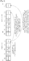
FIG. 2 illustrates an example of a data reception method in a basic in-band signaling system. - Referring to
FIG. 2 , aframe #k 201 and a frame #(k+1) 20 are shown. Frame #k includes apreamble 203, P2-L1 signaling 204, PLP0-L2 signaling 205,PLP_1 206,PLP_2 207 andPLP_N 208, as described in connection withFIG. 1 . Frame #(k+1) 202 includes a preamble 209, P2-L1 signaling 210, PLP0-L2 signaling 211,PLP_1 212,PLP_2 213 andPLP_N 214. - Assume that a particular receiver is receiving a particular broadcast service channel through a PLP_2, as illustrated in
FIG. 2 . The receiver receives thePLP_2 207 being transmitted in theframe #k 201. ThePLP_2 207 includes in-band signaling information. The in-band signaling information may include a location, or dynamic information, of thePLP_2 207 in the next frame, i.e. the frame #(k+1) 202. Based on the dynamic information, the receiver can directly receive thePLP_2 213 in the next frame, without receiving theP2 part 210 to receive thePLP_2 213 as indicated byreference numeral 217. That is, after receiving thePLP_2 207 in theframe #k 201, the receiver may power off its receiving units until it receives the PLP_2 213 (including the next data) of the frame #(k+1) 202, i.e. the next frame, thereby saving the power. - The
PLP_2 207 in theframe #k 201 and thePLP_2 213 in the frame #(k+1) 202 have data for the same broadcast service. In order to distinguish the PLPs, thePLP_2 213 transmitted after thePLP_2 207 in the frame #k, which the receiver is presently receiving, can also be referred to herein as a "next packet". However, the term "next packet" may indicate a data PLP included in any of frames, including not only the frame right after the current frame, but also all its succeeding frames. - The in-band signaling information 216 may include location(s) of one or multiple different data PLPs as indicated by
reference numeral 218. When the receiver makes service switching to thePLP_N 214 while receiving thePLP_2 207, the receiver can obtain location information of thePLP_N 214 in the next frame in advance using the already acquired in-band signaling information. Therefore, the receiver can immediately determine the location of thePLP_N 214 without receiving and demodulating theP2 part 210 of the next frame, thereby reducing its power consumption. - It is assumed in the basic system of
FIG. 2 that the in-band signaling information always includes the location and control information of the immediately next frame (frame #(k+1)) after the current frame (frame #k). However, in case that thePLP_2 207 does not exist in the next frame, an extended system can be defined. -
FIG. 3 illustrates an example of a data reception method in an extended in-band signaling system.Frame #k 251 includes apreamble 253, P2-L1 signaling 254, PLP0-L2 signaling 255,PLP_1 256,PLP_2 257 andPLP_N 258. Frame #(k+N) 252 includes a preamble 259, P2-L1 signaling 260,PLPO signaling 261,PLP_1 262,PLP_2 263 andPLP_N 264. - In
FIG. 3 , whenPLP_2 257 exists in the currentframe #k 251 and the next packet exists not in the next frame #(k+1), but in frame #(k+N) 252 (where N is a natural number greater than or equal to 2), it is possible to record location information of the frame #(k+N) 252 in in-band signaling information as shown by reference numeral 270 inFIG. 3 . This scenario is available when a transmitter can store data PLPs for all services in advance, and a definition thereof can be given only when it is possible to predict location information of data PLPs for all the services in advance, for multiple frames. However, the extended system is unavailable when it is not possible to collect all data PLPs with regard to multiple succeeding frames. - The transmitter in the basic system can schedule up to the next one frame immediately after the current frame, while the transmitter in the extended system can schedule up to the next NMAX frames after the current frame (when the current frame is a frame #k, the last one of the next NMAX frames becomes a frame #(k+NMAX))- A combined system is referred to as a broadcasting system herein, and the maximum number of frames (the maximum number of predictable frames) that the transmitter can schedule is defined as the maximum schedulable period NMAX (where NMAX is a natural number greater than or equal to 1).
- Chris Nokes, "TM-T20396: T2_0396_Baseline_0_3_4" (DVB, Digital Video Broadcasting, Geneva, Switzerland, 1 March 2008) discloses a description of the DVB-T2 baseline system taking as a starting point in the DVB-S2 specification, and identifies techniques yet to be considered for inclusion in the baseline and global performance requirements and features of the T2 system.
- However, in the broadcasting system, when the next packet after a data PLP for a particular broadcast service exists in a frame #(NMAX+1), i.e. when the next packet after a particular data PLP exists in a frame after the last one of the next NMAX frames that the transmitter can schedule, information to be included in in-band signaling information becomes uncertain, making seamless reception impossible at a receiver operating in in-band signaling. Therefore, when an index of the frame where the next packet is transmitted exceeds the maximum number of frames that the transmitter can schedule, receivers cannot receive the packet, causing a packet loss. When an attempt to prevent the packet loss is made, the receivers cannot acquire scheduling information for the next packet until it receives and demodulates LI signaling from a preamble P2 after a delay of the frame #(NMAX+ 1) which is the next frame, generating a fatal error.
- The present invention has been made to address at least the above problems and/or disadvantages and to provide at least the advantages described below. Accordingly, an aspect of the present invention provides an in-band signaling information transmission/reception method and apparatus for maximizing a power saving effect while seamlessly receiving data by in-band signaling as set forth in the appended claims.
- According to one aspect of the present invention, a method is provided for transmitting in-band signaling information in a wireless broadcasting system that transmits broadcast service data through a plurality of data Physical Layer Pipes (PLPs) constituting a frame. Non-PLP signaling information is included in a data PLP for a particular broadcast service and the data PLP is transmitted through a current frame, when no data PLP for the particular broadcast service is transmitted in at least one frame to be transmitted within a maximum schedulable period NMAX from a time the current frame is transmitted. The non-PLP signaling information indicates that no data PLP for the particular broadcast service is transmitted within the maximum schedulable period.
- According to another aspect of the present invention, an apparatus is provided for transmitting in-band signaling information in a wireless broadcasting system that transmits broadcast service data through a plurality of data Physical Layer Pipes (PLPs) constituting a frame. The apparatus includes a transmitter for including non-PLP signaling information in a data PLP for a particular broadcast service and transmitting the data PLP through a current frame, when no data PLP for the particular broadcast service is transmitted within a maximum schedulable period NMAX from a time the current frame is transmitted. The non-PLP signaling information indicates that no data PLP for the particular broadcast service is transmitted through at least one frame, which is to be transmitted within the maximum schedulable period.
- According to a further aspect of the present invention, a method is provided for receiving in-band signaling information in a wireless broadcasting system that transmits broadcast service data through a plurality of data Physical Layer Pipes (PLPs) constituting a frame. Control information for a next packet after a data PLP for a particular broadcast service is acquired from in-band signaling information of the data PLP for the particular broadcast service in an incoming frame. It is determined from the control information whether a frame where the next packet exists is transmitted within a maximum schedulable period NMAX. The next packet in the frame where the next packet exists is found and received, when the frame where the next packet exists is transmitted within the maximum schedulable period.
- According to an additional aspect of the present invention, an apparatus is provided for receiving in-band signaling information in a wireless broadcasting system that transmits broadcast service data through a plurality of data Physical Layer Pipes (PLPs) constituting a frame. The apparatus includes an in-band signaling information extractor for acquiring in-band signaling information of a data PLP for a particular broadcast service in an incoming frame. The apparatus also includes a controller for acquiring control information for a next packet after the data PLP for the particular broadcast service from the acquired in-band signaling information and determining from the control information whether a frame where the next packet exists is transmitted within a maximum schedulable period NMAX. The controller also controls a data PLP receiving unit to determine and receive the next packet in the frame where the next packet exists, when the frame where the next packet exists is transmitted within the maximum schedulable period.
- As is apparent from the foregoing description, the receiver can seamlessly receive data and maximize the power saving effect by transmitting and receiving the in-band signaling information proposed by the present invention.
- The above and other aspects, features and advantages of the present invention will be more apparent from the following detailed description when taken in conjunction with the accompanying drawings, in which:
-
FIG. 1 illustrates a frame structure of a conventional broadcasting system; -
FIG. 2 illustrates an example of a data reception method in a basic in-band signaling system; -
FIG. 3 illustrates an example of a data reception method in an extended in-band signaling system; -
FIGs. 4 and5 are a flow diagrams illustrating an operation of a transmitter according to an embodiment of the present invention; -
FIG. 6 is a flow diagram illustrating an operation of a receiver according to an embodiment of the present invention; -
FIG. 7 is a diagram illustrating a structure of a transmitter apparatus according to an embodiment of the present invention; and -
FIG. 8 is a diagram illustrating a structure of a receiver apparatus according to an embodiment of the present invention. - Preferred embodiments of the present invention are described in detail with reference to the accompanying drawings. The same or similar components may be designated by the same or similar reference numerals although they are illustrated in different drawings. Detailed descriptions of constructions or processes known in the art may be omitted to avoid obscuring the subject matter of the present invention.
- The terms and words used herein are not limited to their dictionary meanings, but, are used by the inventor to enable a clear and consistent understanding of the invention. Accordingly, it should be apparent to those skilled in the art that the following description of embodiments of the present invention are provided for illustration purpose only and not for the purpose of limiting the invention as defined by the appended claims and their equivalents.
- It is to be understood that the singular forms "a", "an", and "the" include plural referents unless the context clearly dictates otherwise. Thus, for example, reference to "a component surface" includes reference to one or more of such surfaces.
-
FIGs. 4 and5 are flow diagrams illustrating an operation of a transmitter according to an embodiment of the present invention. - Referring to
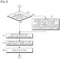
FIGs. 4 and5 , instep 301, the transmitter determines P2 information (L1 static, L1 configurable, and L1 dynamic including a location of each data PLP) and PLPO information of the next frame. Instep 302, the transmitter initializes an in-band signaling part, which is to be multiplexed to data PLPs. The term "next frame" mentioned instep 301 indicates an arbitrary frame among the frames following the current frame #k, and can be any one of a frame #(k+1), a frame #(k+3), and a frame #(k+NMAX). - The following process is branched depending on whether the system in operation can predict control information (scheduling information, IDs of data PLPs in the next frame, etc.) of only the frame immediately after the current frame, or can collect control information for frames beyond the immediately next frame. That is, the transmitter determines in
step 303 whether the system is adapted to include a frame index field for each data PLP in in-band signaling information. When the system is not designed to include a frame index field for each data PLP in in-band signaling information, i.e. when the system can collect control information of only the immediately next frame, the transmitter proceeds to step 350. - Herein, the term "immediately next frame" indicates the frame right after the current frame, and the term "next frame" indicates any frame succeeding the current frame.
- The transmitter determines in
step 350 whether a data PLP for a particular broadcast service, in which in-band signaling information is included, (hereinafter referred to as a "data PLP for a particular broadcast service") exists in the immediately next frame. When a data PLP for the particular broadcast service exists in the immediately next frame, the transmitter includes, instep 351, ID, location and length information of the data PLP for the particular broadcast service in the immediately next frame (#k+1), in an in-band signaling part of the data PLP for the particular broadcast service, which is to be transmitted in the current frame #k. - On the contrary, when a data PLP for the particular broadcast service does not exist in the immediately next frame in
step 350, the transmitter stops collecting any more information on the next packet after the data PLP for the particular broadcast service, instep 352, since it cannot predict control information for more frames (frames after the frame #(k+1)) with the current system. The methodology then proceeds to step 309, with the in-band signaling information for the data PLP for the broadcast service being empty. - If the system in operation can collect in advance control information of all data PLPs in the frame #(k+2), which is the 2nd frame after the frame #k, or the current frame, up to the frame #(k+NMAX), which is the (NMAX)th frame after the frame #k, its operation is as follows.
- That is, the transmitter determines, in
step 303, whether the system can include a frame index field indicating a location of a data PLP in in-band signaling information. When the frame index field is included in the in-band signaling information instep 303, the transmitter proceeds to step 304, since it is meant that the system can collect control information of the frame #(k+2) to the frame #(k+NMAX). - Because the system can predict up to the frame #(k+NMAX) in advance in the current frame #k, the transmitter determines in
step 304 whether a data PLP for a particular broadcast service exists within N frames after the current frame #k. Here, NMAX can be previously agreed upon as a predetermined value by the transmitter and the receiver, or can be provided to the receiver by the transmitter through separate signaling. Compared with an NMAX=1 system, the system that can collect in advance control information of all data PLPs in the frame #(k+2) through the frame #(k+NMAX), can additionally provide information N on the next frame where each data PLP is transmitted, so that a frame index field is included in in-band signaling information. The frame index field is used as information indicating a sequence number of a frame where the next packet after each data PLP exists. - When a data PLP for a particular broadcast service exists in an Nth frame (where 1≤N≤NMAX) in
step 304, the transmitter determines, instep 305, an index of a frame where the next packet after a data PLP for a particular broadcast service exists, and control information such as ID, location and length of each data PLP. The frame index N of the frame where the data PLP is to be transmitted next, and the control information, are included in in-band signaling information of the data PLP for the particular broadcast service, which is to be transmitted in the current frame #k, instep 306. - When a data PLP for the particular broadcast service does not exist within (k+NMAX) frames in
step 304, the transmitter includes information indicating "that a data PLP for a particular broadcast service does not exist at least within (k+NMAX) frames"(hereinafter referred to as "non-PLP signaling information"), in in-band signaling information instep 307. The non-PLP signaling information indicates that no data PLP for the particular broadcast service is transmitted through multiple frames, which will be transmitted within the maximum schedulable period NMAX. - A method for transmitting the non-PLP signaling information can be divided into the following three methods. In a first method, one of the frame index field values may be defined to indicate the non-PLP signaling information. In a second method, a separate field may be defined to indicate the non-PLP signaling information.
- In a third method, the same expression can be made by combining the frame index field defined for the proposed system and data PLP's length information in the existing in-band signaling information. As an example of the third method, the non-PLP signaling information is indicated when the frame index field indicates k+NMAX and the data PLP's length information has a value of 0.
- Referring now to
FIG. 5 , when the generation of the control information for a data PLP for a particular broadcast service is completed insteps step 309 whether there is a need to create control information for a data PLP for another broadcast service. The transmitter determines instep 309 whether there is information on other data PLPs it should further include in in-band signaling information of a data PLP for a particular broadcast service, which is to be transmitted in the current frame. The control information can be made for one data PLP or multiple other data PLPs, selectively. When it is determined instep 309 that control information of other data PLPs should be included for fast service switching, the transmitter adds the control information of other data PLPs in in-band signaling information of the data PLP for the particular broadcast service instep 310. - When the generation of in-band signaling information of the data PLP for the particular broadcast service is completed in
step 310, the transmitter multiplexes the in-band signaling information and data information of the data PLP for the particular broadcast service instep 311. Here, the transmitter repeatedly performs all ofsteps 301 to 311 on each data PLP included in the frame #k. In this way, the transmitter generates and transmits the current frame #k instep 312. Thereafter, the transmitter moves to the next frame instep 360 and returns to step 301 in order to process the next frame. -
FIG. 6 is a flow diagram illustrating an operation of a receiver according to an embodiment of the present invention. - Referring to
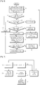
FIG. 6 , the receiver acquires, instep 401, location information of an incoming data PLP (a data PLP which is presently being received) for a particular broadcast service in the next frame, from in-band signaling information of the incoming data PLP. Theprocess following step 401 is branched according to whether the system in operation is a system having a frame index field to support NMAX ≥ 2, or a system capable of transmitting control information of only the frame right after the current frame without the frame index field. That is, the receiver determines instep 402 whether the system in operation supports frame index information of an incoming data PLP for a particular broadcast service, and proceeds to one ofsteps - When it is determined in
step 402 that the system can transmit control information of only the frame right after the current frame #k, the receiver determines instep 404 whether control information of a data PLP for a particular broadcast service exists in in-band signaling information. When the control information of the data PLP for the particular broadcast service exists in the in-band signaling information, the receiver moves to a frame #(k+1), or the frame right after the current frame instep 409, recognizing that a data PLP for the particular broadcast service exists in the frame #(k+1). Instep 410, the receiver determines a location of the data PLP in the frame #(k+1) and receives data on the data PLP. Afterstep 410, the receiver returns to step 401 and demodulates in-band signaling information existing in an incoming data PLP for the particular broadcast service. - Otherwise, when it is determined in
step 404 that control information of a data PLP for a particular broadcast service does not exist in in-band signaling information of the immediately next frame, or the frame #(k+1), the receiver proceeds to step 405, determining that a data PLP for the particular broadcast service does not exist in the immediately next frame #(k+1), and moves by 2 frames to a frame #(k+2), which is a frame after the frame #(k+1). - Thereafter, because the receiver can no longer acquire location information of the data PLP for the particular broadcast service from the in-band signaling information, the receiver necessarily receives, in
step 406, a P2 part in the frame #(k+2), which is the frame the receiver is presently receiving, and acquires an ID and location information of the data PLP for the particular broadcast service, included in the frame #(k+2). When a data PLP for the particular broadcast service exists in the frame #(k+2) instep 407, the receiver determines, instep 411, a location of the data PLP for the particular broadcast service in the frame #(k+2) and receives data in the location. - After
step 411, the receiver acquires in-band signaling information from a data PLP for a particular broadcast service, and acquires again control information in the next frame using the acquired in-band signaling information instep 401. - So far, a description has been given of a receiver's operation when the system has control information of only the frame right after the current frame.
- For a system that can acquire and transmit control information for a frame after multiple frames, a receiver's operation is as follows. That is, the receiver determines in
step 402 whether the system supports frame index information of an incoming data PLP for a particular broadcast service. When the system supports frame index information of the data PLP, the receiver determines instep 403 whether an incoming data PLP exists in an Nth frame. Here, the receiver determines whether an incoming data PLP for a particular broadcast service exists in an Nth frame, based on the non-PLP signaling information described instep 307. Upon recognizing instep 403 that an incoming data PLP for a particular broadcast service exists in an Nth(≤NMAX) frame, the receiver immediately waits for N frames instep 412, and then receives data in a location of the data PLP for the particular broadcast service in the frame #(k+N) instep 410. - However, upon detecting in
step 403 that an incoming data PLP for a particular broadcast service does not exist within the next (NMAX)th frame (i.e. a frame #(k+NMAX )), the receiver delays up to an (NMAX+1)th frame (i.e. a frame k+NMAX+1) after the current frame instep 413, and necessarily receives a P2 part of the frame #(k+NMAX+1) instep 406. The receiver determines instep 407 whether a data PLP for the particular broadcast service exists in the frame #(k+NMAX+1). When no data PLP for the particular broadcast service exists in the received frame instep 407, the receiver moves to the next frame instep 408.Steps -
FIG. 7 is a diagram illustrating a structure of a transmitter apparatus according to an embodiment of the present invention. Referring toFIG. 7 , the transmitter includes ascheduler 501, acontroller 502, an in-bandsignaling information generator 503, aframe generator 504, atransmission data buffer 505, and aframe transmitter 506. - The
transmission data buffer 505 is a memory in which transmission data for several broadcast service channels is buffered. Thescheduler 501 performs predetermined scheduling depending on the state of the buffered data. The scheduling operation includes determining control information such as an ID and location information of a data PLP for a particular frame. The scheduling result is provided to thecontroller 502. Thecontroller 502 controls the in-bandsignaling information generator 503 to generate in-band signaling information as described in connection withFIGs. 4 and5 , and also controls theframe generator 504 to generate one frame by controlling outputs of thetransmission data buffer 505 and the in-bandsignaling information generator 503. The generated frame is transmitted by theframe transmitter 506 as described with reference toFIGs. 4 and5 . Theframe transmitter 506 may be equal to a common Orthogonal Frequency Division Multiplexing (OFDM) signal transmitter. - In an embodiment of the present invention, when no data PLP for a particular broadcast service is transmitted in at least one frame which is to be transmitted within the maximum schedulable period NMAX after the time the current frame is transmitted, the transmitter includes non-PLP signaling information in the data PLP for the particular broadcast service and transmits it through the current frame. In addition, when the data PLP does not have the frame index field and a data PLP for the particular broadcast service does not exist in the frame, which is to be transmitted immediately after the current frame, the transmitter transmits the current frame with in-band signaling information to be transmitted in the data PLP being empty. Further, when the data PLP does not include the frame index field and a data PLP for the particular broadcast service exists in the frame which is to be transmitted right after the current frame, the transmitter inserts control information for the data PLP for the particular broadcast service into in-band signaling information to be included in the data PLP within a frame to be transmitted immediately after the current frame, and then transmits the current frame.
- In addition, when the data PLP includes the frame index field and a data PLP for the particular broadcast service exists in a frame to be transmitted after the current frame within the maximum schedulable period NMAX, the transmitter determines an index of a frame where a data PLP for the particular broadcast service exists, in in-band signaling information to be included in the data PLP. The transmitter also determines control information for the data PLP for the particular broadcast service, inserts the determined frame index and control information for the data PLP for the particular broadcast service into the current frame, and transmits the current frame.
- Meanwhile, the transmitter may indicate non-existence of a data PLP for the particular broadcast service in a frame to be transmitted after the current frame within the maximum schedulable period in the three methods described above.
- In the first method, when the data PLP includes the frame index field and a data PLP for the particular broadcast service does not exist in a frame to be transmitted after the current frame within the maximum schedulable period NMAX, the transmitter indicates non-existence of the data PLP for the particular broadcast service in a frame to be transmitted after the current frame within the maximum schedulable period using one of the frame index field's values of the data PLP.
- In the second method, when the data PLP includes the frame index field and a data PLP for the particular broadcast service does not exist in a frame to be transmitted after the current frame within the maximum schedulable period NMAX, the transmitter indicates non-existence of the data PLP for the particular broadcast service in a frame to be transmitted after the current frame within the maximum schedulable period by defining a separate field in the data PLP.
- In the third method, when the data PLP includes the frame index field and a data PLP for the particular broadcast service does not exist in a frame to be transmitted after the current frame within the maximum schedulable period NMAX, the transmitter indicates non-existence of the data PLP for the particular broadcast service in a frame to be transmitted after the current frame within the maximum schedulable period by combining the frame index field with length information of the data PLP.
-
FIG. 8 is a diagram illustrating a structure of a receiver apparatus according to an embodiment of the present invention. - Referring to
FIG. 8 , the receiver includes a dataPLP receiving unit 601, a physical layer (P2)receiving unit 603, an in-bandsignaling information extractor 602, and acontroller 604. The data PLP receivingunit 601 is a part for receiving a desired data PLP using a common OFDM signal receiver. The in-bandsignaling information extractor 602 is a block for extracting in-band signaling information from the data obtained by the data PLP receivingunit 601. The extracted in-band signaling information is provided to thecontroller 604. Thecontroller 604 delays as many frames as it wants, using the in-band signaling information, and then controls the data PLP receivingunit 601 or theP2 receiving unit 603 as described in connection withFIG. 6 . - In an embodiment of the present invention, the
controller 604 acquires control information for the next packet after the data PLP for the particular broadcast service from the in-band signaling information acquired by the in-bandsignaling information extractor 602, and determines from the control information whether a frame where the next packet exists is transmitted within the maximum schedulable period NMAX. When the frame where the next packet exists is transmitted within the maximum schedulable period NMAX, thecontroller 604 controls the data PLP receivingunit 601 to determine and receive the next packet in the frame where the next packet exists. - In addition, when the frame where the next packet exists is transmitted after the maximum schedulable period, the
controller 604 controls theP2 receiving unit 603 to receive physical layer signaling information in a frame #(NMAX+1) after the maximum schedulable period from the current frame, and controls the data PLP receivingunit 601 to receive the next packet using the received physical layer signaling information. As stated instep 403 ofFIG. 6 , thecontroller 604 determines whether the frame where the next packet exists is transmitted within the maximum schedulable period, using any one of a frame index field value included in the in-band signaling information of the data PLP for the particular broadcast service, a separate field indicating whether the next packet is transmitted in the maximum schedulable period, and a combination of the frame index field and length information of the data PLP. - Moreover, when the frame index information does not exist in the data PLP and no data PLP for the particular broadcast service exists in the next frame, the
controller 604 controls theP2 receiving unit 603 to receive physical layer signaling information in a frame #(k+2) that comes two frames after the current frame #k, and also controls the data PLP receivingunit 601 to receive the next packet using the received physical layer signaling information. - Embodiments of the present invention can also be embodied as computer-readable codes on a computer-readable recording medium. The computer-readable recording medium is any data storage device that can store data, which can thereafter be read by a computer system. Examples of the computer-readable recording medium include, but are not limited to, Read-Only Memory (ROM), Random-Access Memory (RAM), CD-ROMs, magnetic tapes, floppy disks, optical data storage devices, and carrier waves (such as data transmission through the Internet via wired or wireless transmission paths). The computer-readable recording medium can also be distributed over network-coupled computer systems so that the computer-readable code is stored and executed in a distributed fashion. Also, function programs, codes, and code segments for accomplishing the present invention can be easily construed as within the scope of the invention by programmers skilled in the art to which the present invention pertains.
- While the invention has been shown and described with reference to a certain preferred embodiments thereof, it will be understood by those skilled in the art that various changes in form and details may be made therein without departing from the scope of the invention as defined by the appended claims.
Claims (14)
- A method for transmitting in-band signaling information by a transmitter in a wireless broadcasting system that transmits broadcast service data through a plurality of data physical layer pipes, PLPs, constituting a frame, the method comprising the steps of:determining whether it is possible to include frame index information indicating a location of a data PLP for a first data PLP to be transmitted, in in-band signaling information of a current data PLP for a particular broadcast service;if it is possible to include the frame index information in the in-band signaling information and no data PLP for the particular broadcast service is transmitted within a predefined period of N frames, N>=2, from a current frame, transmitting the in-band signaling information including the frame index information, the frame index information including non-PLP signaling information indicating that no data PLP for the particular broadcast service is transmitted within the predefined period from the current frame; andif it is impossible to include the frame index information in the in-band signaling information and no data PLP for the particular broadcast service is transmitted in an immediately next frame after the current frame, indicating that no data PLP is transmitted in the immediately next frame by emptying the in-band signaling information.
- The method of claim 1, further comprising:transmitting the in-band signaling information including control information related to the first data PLP to be transmitted for the particular broadcast service in the current frame, if it is possible to include the frame index information in the in-band signaling information and the first data PLP for the particular broadcast service to be transmitted within the predefined period from the current frame exists,wherein the control information includes length information of the first data PLP, frame index information for a frame where the first data PLP is to be transmitted, and identity information of the first data PLP.
- The method of claim 1, further comprising:transmitting the in-band signaling information including control information related to the first data PLP to be transmitted for the particular broadcast service in the current frame, if it is impossible to include the frame index information in the in-band signaling information and the first data PLP for the particular broadcast service to be transmitted in an immediately nextframe after the current frame exists,wherein the control information includes length information of the first data PLP, location information of the first data PLP in the immediately next frame, and identity information of the first data PLP.
- A method for receiving in-band signaling information by a receiver in a wireless broadcasting system that transmits broadcast service data through a plurality of data physical layer pipes, PLPs, constituting a frame, the method comprising:receiving, from a transmitter, the in-band signaling information of a data PLP for a particular broadcast service in a current frame,if the in-band signaling information includes frame index information indicating a location of a data PLP and the frame index information includes non-PLP signaling information, determining that no data PLP is transmitted within a predefined period of N frames, N>=2, from the current frame; andif the in-band signaling information does not include the frame index information and the in-band signaling information is empty, determining that no data PLP is transmitted in an immediately next frame after the current frame, wherein the non-PLP signaling information indicates that no data PLP for the particular broadcast service is transmitted within the predefined period from the current frame.
- The method of claim 1, or the method of claim 4, wherein the predefined period is a maximum schedulable period of the transmitter.
- The method of claim 4, further comprising:if the in-band signaling information includes control information related to a next data PLP to be transmitted for the particular broadcast service, determining the next data PLP for the particular broadcast service to be transmitted within the predefined period from the current frame exists, and obtaining the next data PLP based on control information,wherein the control information includes length information of the next data PLP, frame index information for a frame where the next data PLP is to be transmitted, and identity information of the next data PLP.
- The method of claim 4, further comprising:if the in-band signaling information does not include the frame index information and the in-band signaling information includes control information related to an immediately next data PLP to be transmitted for the particular broadcast service, determining the immediately next data PLP for the particular broadcast service to be transmitted in a next frame after the current frame exists, and obtaining the next data PLP based on control information,wherein the control information includes length information of the next data PLP, location information of the next data PLP, and identity information of the next data PLP.
- A transmitting apparatus for transmitting in-band signaling information by a transmitter in a wireless broadcasting system that transmits broadcast service data through a plurality of data physical layer pipes, PLPs, constituting a frame, the transmitting apparatus comprising:a transmitter; anda controller configured to:determine whether it is possible to include frame index information indicating a location of a data PLP for a first data PLP to be transmitted, in in-band signaling information of a current data PLP for a particular broadcast service;if it is possible to include the frame index information in the in-band signaling information and no data PLP for the particular broadcast service is transmitted within a predefined period of N frames, N>=2, from a current frame, control the transmitter to transmit the in-band signaling information including the frame index information, the frame index information including non-PLP signaling information indicating that no data PLP for the particular broadcast service is transmitted within the predefined period from the current frame; andif it is impossible to include the frame index information in the in-band signaling information and no data PLP for the particular broadcast service is transmitted in an immediately next frame after the current frame, indicate that no data PLP is transmitted in the immediately next frame by emptying the in-band signaling information.
- The transmitting apparatus of claim 8, wherein the controller is further configured to:control the transmitter to transmit the in-band signaling information including control information related to the first data PLP to be transmitted for the particular broadcast service in the current frame, if it is possible to include the frame index information in the in-band signaling information and the first data PLP for the particular broadcast service to be transmitted within the predefined period from the current frame exists,wherein the control information includes length information of the first data PLP, frame index information for a frame where the first data PLP is to be transmitted, and identity information of the first data PLP.
- The transmitting apparatus of claim 8, wherein the controller is further configured to:control the transmitter to transmit the in-band signaling information including control information related to the first data PLP to be transmitted for the particular broadcast service in the current frame, if it is impossible to include the frame index information in the in-band signaling information and the first data PLP for the particular broadcast service to be transmitted in an immediately next frame after the current frame exists,wherein the control information includes length information of the first data PLP, location information of the first data PLP in the immediately next frame, and identity information of the first data PLP.
- A receiving apparatus for receiving in-band signaling information by a receiver in a wireless broadcasting system that transmits broadcast service data through a plurality of data physical layer pipes, PLPs, constituting a frame, the method comprising:a receiver configured to receive, from a transmitting apparatus, the in-band signaling information of a data PLP for a particular broadcast service in a current frame; anda controller configured to:if the in-band signaling information includes frame index information indicating a location of a data PLP and the frame index information includes non-PLP signaling information, determine that no data PLP is transmitted within a predefined of N frames, N>=2, from the current frame, andif the in-band signaling information does not include the frame index information and the in-band signaling information is empty, determine that no data PLP is transmitted in an immediately next frame after the current frame,wherein the non-PLP signaling information indicates that no data PLP for the particular broadcast service is transmitted within the predefined period from the current frame.
- The transmitting apparatus of claim 8, or the receiving apparatus of claim 11, wherein the predefined period is a maximum schedulable period of the transmitting apparatus.
- The receiving apparatus of claim 11, wherein the controller is further configured to:if the in-band signaling information includes control information related to a next data PLP to be transmitted for the particular broadcast service, determine the next data PLP for the particular broadcast service to be transmitted within the predefined period from the current frame exists and obtain the next data PLP based on control information,wherein the control information includes length information of the next data PLP, frame index information for a frame where the next data PLP is to be transmitted, and identity information of the next data PLP.
- The receiving apparatus of claim 11, wherein the controller is further configured to:if the in-band signaling information does not include the frame index information and the in-band signaling information includes control information related to an immediately next data PLP to be transmitted for the particular broadcast service, determine the next data PLP for the particular broadcast service to be transmitted in an immediately next frame after the current frame exists and obtain the next data PLP based on control information,wherein the control information includes length information of the next data PLP, location information of the next data PLP, and identity information of the next data PLP.
Applications Claiming Priority (2)
| Application Number | Priority Date | Filing Date | Title |
|---|---|---|---|
| KR1020080019636A KR101388794B1 (en) | 2008-03-03 | 2008-03-03 | Method and apparatus for transmitting/receiving in-band signal information in wireless broadcasting system |
| PCT/KR2009/001039 WO2009110731A2 (en) | 2008-03-03 | 2009-03-03 | Method and apparatus for transmitting and receiving in-band signaling information in a wireless broadcasting system |
Publications (3)
| Publication Number | Publication Date |
|---|---|
| EP2263357A2 EP2263357A2 (en) | 2010-12-22 |
| EP2263357A4 EP2263357A4 (en) | 2016-05-18 |
| EP2263357B1 true EP2263357B1 (en) | 2019-05-01 |
Family
ID=41013123
Family Applications (1)
| Application Number | Title | Priority Date | Filing Date |
|---|---|---|---|
| EP09717236.5A Active EP2263357B1 (en) | 2008-03-03 | 2009-03-03 | Method and apparatus for transmitting and receiving in-band signaling information in a wireless broadcasting system |
Country Status (7)
| Country | Link |
|---|---|
| US (1) | US8565265B2 (en) |
| EP (1) | EP2263357B1 (en) |
| JP (1) | JP5187916B2 (en) |
| KR (1) | KR101388794B1 (en) |
| CN (1) | CN101960811B (en) |
| AU (1) | AU2009220326B2 (en) |
| WO (1) | WO2009110731A2 (en) |
Families Citing this family (16)
| Publication number | Priority date | Publication date | Assignee | Title |
|---|---|---|---|---|
| JP2010232895A (en) * | 2009-03-26 | 2010-10-14 | Fuji Xerox Co Ltd | Communication controller and information processor |
| US20110055887A1 (en) * | 2009-08-26 | 2011-03-03 | Nokia Corporation | Tunneling and Signaling of Content in Legacy Formats |
| WO2011099749A2 (en) | 2010-02-12 | 2011-08-18 | 엘지전자 주식회사 | Broadcasting signal transmitter/receiver and broadcasting signal transmission/reception method |
| US10027518B2 (en) * | 2010-02-12 | 2018-07-17 | Lg Electronics Inc. | Broadcasting signal transmitter/receiver and broadcasting signal transmission/reception method |
| EP2362654A1 (en) * | 2010-02-26 | 2011-08-31 | Panasonic Corporation | Short baseband frame headers |
| US20120216230A1 (en) * | 2011-02-18 | 2012-08-23 | Nokia Corporation | Method and System for Signaling Transmission Over RTP |
| GB201208389D0 (en) * | 2012-05-10 | 2012-06-27 | Samsung Electronics Co Ltd | Integrated circuit, communication unit, wireless communication system and methods therefor |
| EP2672393A1 (en) * | 2012-06-04 | 2013-12-11 | Dialog Semiconductor B.V. | Circuit and methods to use an audio interface to program a device within an audio stream |
| US20160227274A1 (en) * | 2013-09-15 | 2016-08-04 | Lg Electronics Inc. | Broadcast receiving device and method for operating the same |
| CN105515732B (en) * | 2014-09-24 | 2018-01-09 | 上海朗帛通信技术有限公司 | A kind of method and apparatus for multi-antenna communication in UE, base station |
| WO2016144072A1 (en) * | 2015-03-08 | 2016-09-15 | 엘지전자(주) | Apparatus and method for transmitting and receiving broadcast signal |
| WO2016148537A1 (en) * | 2015-03-19 | 2016-09-22 | 엘지전자(주) | Apparatus and method for receiving/transmitting broadcast signal |
| CN107431562B (en) * | 2015-04-06 | 2021-06-18 | Lg电子株式会社 | Apparatus and method for transmitting and receiving broadcast signal |
| EP3324593A4 (en) | 2015-07-16 | 2019-03-20 | LG Electronics Inc. | Broadcast signal transmitting device, broadcast signal receiving device, broadcast signal transmitting method, and broadcast signal receiving method |
| US11202112B2 (en) * | 2016-03-04 | 2021-12-14 | Samsung Electronics Co., Ltd. | Receiver and PLP processing method therefor |
| JP6953693B2 (en) * | 2016-09-15 | 2021-10-27 | ソニーグループ株式会社 | Transmission device and transmission method |
Family Cites Families (14)
| Publication number | Priority date | Publication date | Assignee | Title |
|---|---|---|---|---|
| KR100433908B1 (en) * | 2001-10-29 | 2004-06-04 | 삼성전자주식회사 | Apparatus and method for transmitting/receiving an error detection information in telecommunications system |
| US8126127B2 (en) * | 2002-01-16 | 2012-02-28 | Qualcomm Incorporated | Method and apparatus for provision of broadcast service information |
| KR20050014599A (en) * | 2003-07-31 | 2005-02-07 | 삼성전자주식회사 | Method for efficiently paging an user equipment to transmit control information in a mobile communication system |
| KR20050105901A (en) * | 2004-05-03 | 2005-11-08 | 삼성전자주식회사 | Broadcasting service method and system in wireless telecommunication system |
| KR100800887B1 (en) * | 2004-05-07 | 2008-02-04 | 삼성전자주식회사 | Method and system for transmitting/receiving data of broadcast service data in a wireless communication system |
| KR100891783B1 (en) * | 2004-06-25 | 2009-04-07 | 삼성전자주식회사 | Method for transmitting and receiving data of broadcast service in a wireless communication system usign ofdma |
| US20100185717A9 (en) * | 2005-03-10 | 2010-07-22 | Dhinakar Radhakrishnan | Method of improving control information acquisition latency by transmitting control information in individually decode-able packets |
| ATE554549T1 (en) | 2005-03-10 | 2012-05-15 | Qualcomm Inc | IMPROVE TAX INFORMATION COLLECTION LATENCY BY TRANSMITTING TAX INFORMATION IN INDIVIDUAL DECODABLE PACKETS |
| US7979561B2 (en) | 2005-03-10 | 2011-07-12 | Qualcomm Incorporated | Method of multiplexing over an error-prone wireless broadcast channel |
| US20090094356A1 (en) * | 2007-10-09 | 2009-04-09 | Nokia Corporation | Associating Physical Layer Pipes and Services Through a Program Map Table |
| US7974254B2 (en) * | 2007-10-22 | 2011-07-05 | Nokia Corporation | Digital broadcast signaling metadata |
| US8248910B2 (en) * | 2008-01-29 | 2012-08-21 | Nokia Corporation | Physical layer and data link layer signalling in digital video broadcast preamble symbols |
| US8498262B2 (en) * | 2008-02-13 | 2013-07-30 | Nokia Corporation | Digital broadcast receiver capacity signalling metadata |
| EP2093912B1 (en) * | 2008-02-21 | 2018-04-25 | Samsung Electronics Co., Ltd. | Apparatus and method for receiving a frame including control information in a broadcasting system |
-
2008
- 2008-03-03 KR KR1020080019636A patent/KR101388794B1/en active IP Right Grant
-
2009
- 2009-03-03 AU AU2009220326A patent/AU2009220326B2/en not_active Ceased
- 2009-03-03 EP EP09717236.5A patent/EP2263357B1/en active Active
- 2009-03-03 JP JP2010549568A patent/JP5187916B2/en not_active Expired - Fee Related
- 2009-03-03 US US12/396,982 patent/US8565265B2/en active Active
- 2009-03-03 CN CN2009801075604A patent/CN101960811B/en not_active Expired - Fee Related
- 2009-03-03 WO PCT/KR2009/001039 patent/WO2009110731A2/en active Application Filing
Non-Patent Citations (1)
| Title |
|---|
| None * |
Also Published As
| Publication number | Publication date |
|---|---|
| KR20090094592A (en) | 2009-09-08 |
| AU2009220326A1 (en) | 2009-09-11 |
| WO2009110731A3 (en) | 2009-12-03 |
| WO2009110731A2 (en) | 2009-09-11 |
| CN101960811B (en) | 2013-07-24 |
| US20090219918A1 (en) | 2009-09-03 |
| JP5187916B2 (en) | 2013-04-24 |
| JP2011519191A (en) | 2011-06-30 |
| EP2263357A2 (en) | 2010-12-22 |
| EP2263357A4 (en) | 2016-05-18 |
| AU2009220326B2 (en) | 2013-04-18 |
| CN101960811A (en) | 2011-01-26 |
| KR101388794B1 (en) | 2014-04-23 |
| US8565265B2 (en) | 2013-10-22 |
Similar Documents
| Publication | Publication Date | Title |
|---|---|---|
| EP2263357B1 (en) | Method and apparatus for transmitting and receiving in-band signaling information in a wireless broadcasting system | |
| EP2096777B1 (en) | Apparatus and method for receiving a frame including control information in a broadcasting system | |
| CN112073167B (en) | Transmission method, receiving method, base station and user equipment of synchronous signal block | |
| EP2506607B1 (en) | Receiving broadcast service data in a wireless communication system | |
| US9386560B2 (en) | Transmission of MBMS in an OFDM communication system | |
| RU2594892C2 (en) | Method and telecommunication system | |
| AU2009216037B2 (en) | Apparatus and method for transmitting and receiving a frame including control information in a broadcasting system | |
| US20070189289A1 (en) | Apparatus, method and computer program product providing frequency domain multiplexed multicast and unicast transmissions | |
| JP2008131209A (en) | Communication control device and its control method, communication device and its control method, radio communication system, program and storage medium | |
| CN110719157B (en) | Information sending method, information receiving method, user equipment and base station | |
| CN101552950A (en) | Method and device for transmitting multimedia broadcast multicast service control data | |
| CN101686082B (en) | Downlink synchronizing method and terminal | |
| JP5513554B2 (en) | Control device and control method thereof, communication device and control method thereof, wireless communication system, and program | |
| CN117322019A (en) | Transmission synchronization method and device and storage medium | |
| WO2008114943A1 (en) | Transmitting and receiving method and apparatus for digital television broadcasting data | |
| KR20090029142A (en) | Apparatus and method of packet allocation for time division multiplexing with multiple rf channel |
Legal Events
| Date | Code | Title | Description |
|---|---|---|---|
| PUAI | Public reference made under article 153(3) epc to a published international application that has entered the european phase |
Free format text: ORIGINAL CODE: 0009012 |
|
| 17P | Request for examination filed |
Effective date: 20100901 |
|
| AK | Designated contracting states |
Kind code of ref document: A2 Designated state(s): AT BE BG CH CY CZ DE DK EE ES FI FR GB GR HR HU IE IS IT LI LT LU LV MC MK MT NL NO PL PT RO SE SI SK TR |
|
| AX | Request for extension of the european patent |
Extension state: AL BA RS |
|
| DAX | Request for extension of the european patent (deleted) | ||
| RAP1 | Party data changed (applicant data changed or rights of an application transferred) |
Owner name: SAMSUNG ELECTRONICS CO., LTD. |
|
| A4 | Supplementary search report drawn up and despatched |
Effective date: 20160418 |
|
| RIC1 | Information provided on ipc code assigned before grant |
Ipc: H04L 29/02 20060101AFI20160412BHEP Ipc: H04L 29/06 20060101ALI20160412BHEP Ipc: H04L 5/00 20060101ALI20160412BHEP Ipc: H04L 29/08 20060101ALI20160412BHEP Ipc: H04J 3/12 20060101ALI20160412BHEP Ipc: H04H 60/06 20080101ALI20160412BHEP |
|
| STAA | Information on the status of an ep patent application or granted ep patent |
Free format text: STATUS: EXAMINATION IS IN PROGRESS |
|
| 17Q | First examination report despatched |
Effective date: 20180219 |
|
| GRAP | Despatch of communication of intention to grant a patent |
Free format text: ORIGINAL CODE: EPIDOSNIGR1 |
|
| STAA | Information on the status of an ep patent application or granted ep patent |
Free format text: STATUS: GRANT OF PATENT IS INTENDED |
|
| RIC1 | Information provided on ipc code assigned before grant |
Ipc: H04L 29/02 20060101AFI20180927BHEP Ipc: H04L 29/06 20060101ALI20180927BHEP Ipc: H04L 29/08 20060101ALI20180927BHEP Ipc: H04H 60/06 20080101ALI20180927BHEP Ipc: H04J 3/12 20060101ALI20180927BHEP Ipc: H04L 12/18 20060101ALI20180927BHEP Ipc: H04H 20/30 20080101ALI20180927BHEP Ipc: H04L 5/00 20060101ALI20180927BHEP |
|
| INTG | Intention to grant announced |
Effective date: 20181018 |
|
| GRAS | Grant fee paid |
Free format text: ORIGINAL CODE: EPIDOSNIGR3 |
|
| GRAA | (expected) grant |
Free format text: ORIGINAL CODE: 0009210 |
|
| STAA | Information on the status of an ep patent application or granted ep patent |
Free format text: STATUS: THE PATENT HAS BEEN GRANTED |
|
| AK | Designated contracting states |
Kind code of ref document: B1 Designated state(s): AT BE BG CH CY CZ DE DK EE ES FI FR GB GR HR HU IE IS IT LI LT LU LV MC MK MT NL NO PL PT RO SE SI SK TR |
|
| REG | Reference to a national code |
Ref country code: GB Ref legal event code: FG4D |
|
| REG | Reference to a national code |
Ref country code: CH Ref legal event code: EP Ref country code: AT Ref legal event code: REF Ref document number: 1128445 Country of ref document: AT Kind code of ref document: T Effective date: 20190515 |
|
| REG | Reference to a national code |
Ref country code: DE Ref legal event code: R096 Ref document number: 602009058109 Country of ref document: DE |
|
| REG | Reference to a national code |
Ref country code: IE Ref legal event code: FG4D |
|
| REG | Reference to a national code |
Ref country code: NL Ref legal event code: MP Effective date: 20190501 |
|
| REG | Reference to a national code |
Ref country code: LT Ref legal event code: MG4D |
|
| PG25 | Lapsed in a contracting state [announced via postgrant information from national office to epo] |
Ref country code: PT Free format text: LAPSE BECAUSE OF FAILURE TO SUBMIT A TRANSLATION OF THE DESCRIPTION OR TO PAY THE FEE WITHIN THE PRESCRIBED TIME-LIMIT Effective date: 20190901 Ref country code: SE Free format text: LAPSE BECAUSE OF FAILURE TO SUBMIT A TRANSLATION OF THE DESCRIPTION OR TO PAY THE FEE WITHIN THE PRESCRIBED TIME-LIMIT Effective date: 20190501 Ref country code: NL Free format text: LAPSE BECAUSE OF FAILURE TO SUBMIT A TRANSLATION OF THE DESCRIPTION OR TO PAY THE FEE WITHIN THE PRESCRIBED TIME-LIMIT Effective date: 20190501 Ref country code: ES Free format text: LAPSE BECAUSE OF FAILURE TO SUBMIT A TRANSLATION OF THE DESCRIPTION OR TO PAY THE FEE WITHIN THE PRESCRIBED TIME-LIMIT Effective date: 20190501 Ref country code: LT Free format text: LAPSE BECAUSE OF FAILURE TO SUBMIT A TRANSLATION OF THE DESCRIPTION OR TO PAY THE FEE WITHIN THE PRESCRIBED TIME-LIMIT Effective date: 20190501 Ref country code: FI Free format text: LAPSE BECAUSE OF FAILURE TO SUBMIT A TRANSLATION OF THE DESCRIPTION OR TO PAY THE FEE WITHIN THE PRESCRIBED TIME-LIMIT Effective date: 20190501 Ref country code: HR Free format text: LAPSE BECAUSE OF FAILURE TO SUBMIT A TRANSLATION OF THE DESCRIPTION OR TO PAY THE FEE WITHIN THE PRESCRIBED TIME-LIMIT Effective date: 20190501 Ref country code: NO Free format text: LAPSE BECAUSE OF FAILURE TO SUBMIT A TRANSLATION OF THE DESCRIPTION OR TO PAY THE FEE WITHIN THE PRESCRIBED TIME-LIMIT Effective date: 20190801 |
|
| PG25 | Lapsed in a contracting state [announced via postgrant information from national office to epo] |
Ref country code: GR Free format text: LAPSE BECAUSE OF FAILURE TO SUBMIT A TRANSLATION OF THE DESCRIPTION OR TO PAY THE FEE WITHIN THE PRESCRIBED TIME-LIMIT Effective date: 20190802 Ref country code: LV Free format text: LAPSE BECAUSE OF FAILURE TO SUBMIT A TRANSLATION OF THE DESCRIPTION OR TO PAY THE FEE WITHIN THE PRESCRIBED TIME-LIMIT Effective date: 20190501 Ref country code: BG Free format text: LAPSE BECAUSE OF FAILURE TO SUBMIT A TRANSLATION OF THE DESCRIPTION OR TO PAY THE FEE WITHIN THE PRESCRIBED TIME-LIMIT Effective date: 20190801 |
|
| REG | Reference to a national code |
Ref country code: AT Ref legal event code: MK05 Ref document number: 1128445 Country of ref document: AT Kind code of ref document: T Effective date: 20190501 |
|
| PG25 | Lapsed in a contracting state [announced via postgrant information from national office to epo] |
Ref country code: IS Free format text: LAPSE BECAUSE OF FAILURE TO SUBMIT A TRANSLATION OF THE DESCRIPTION OR TO PAY THE FEE WITHIN THE PRESCRIBED TIME-LIMIT Effective date: 20190901 |
|
| PG25 | Lapsed in a contracting state [announced via postgrant information from national office to epo] |
Ref country code: DK Free format text: LAPSE BECAUSE OF FAILURE TO SUBMIT A TRANSLATION OF THE DESCRIPTION OR TO PAY THE FEE WITHIN THE PRESCRIBED TIME-LIMIT Effective date: 20190501 Ref country code: AT Free format text: LAPSE BECAUSE OF FAILURE TO SUBMIT A TRANSLATION OF THE DESCRIPTION OR TO PAY THE FEE WITHIN THE PRESCRIBED TIME-LIMIT Effective date: 20190501 Ref country code: EE Free format text: LAPSE BECAUSE OF FAILURE TO SUBMIT A TRANSLATION OF THE DESCRIPTION OR TO PAY THE FEE WITHIN THE PRESCRIBED TIME-LIMIT Effective date: 20190501 Ref country code: CZ Free format text: LAPSE BECAUSE OF FAILURE TO SUBMIT A TRANSLATION OF THE DESCRIPTION OR TO PAY THE FEE WITHIN THE PRESCRIBED TIME-LIMIT Effective date: 20190501 Ref country code: RO Free format text: LAPSE BECAUSE OF FAILURE TO SUBMIT A TRANSLATION OF THE DESCRIPTION OR TO PAY THE FEE WITHIN THE PRESCRIBED TIME-LIMIT Effective date: 20190501 Ref country code: SK Free format text: LAPSE BECAUSE OF FAILURE TO SUBMIT A TRANSLATION OF THE DESCRIPTION OR TO PAY THE FEE WITHIN THE PRESCRIBED TIME-LIMIT Effective date: 20190501 |
|
| REG | Reference to a national code |
Ref country code: DE Ref legal event code: R097 Ref document number: 602009058109 Country of ref document: DE |
|
| PG25 | Lapsed in a contracting state [announced via postgrant information from national office to epo] |
Ref country code: IT Free format text: LAPSE BECAUSE OF FAILURE TO SUBMIT A TRANSLATION OF THE DESCRIPTION OR TO PAY THE FEE WITHIN THE PRESCRIBED TIME-LIMIT Effective date: 20190501 |
|
| PLBE | No opposition filed within time limit |
Free format text: ORIGINAL CODE: 0009261 |
|
| STAA | Information on the status of an ep patent application or granted ep patent |
Free format text: STATUS: NO OPPOSITION FILED WITHIN TIME LIMIT |
|
| PG25 | Lapsed in a contracting state [announced via postgrant information from national office to epo] |
Ref country code: TR Free format text: LAPSE BECAUSE OF FAILURE TO SUBMIT A TRANSLATION OF THE DESCRIPTION OR TO PAY THE FEE WITHIN THE PRESCRIBED TIME-LIMIT Effective date: 20190501 |
|
| 26N | No opposition filed |
Effective date: 20200204 |
|
| PG25 | Lapsed in a contracting state [announced via postgrant information from national office to epo] |
Ref country code: PL Free format text: LAPSE BECAUSE OF FAILURE TO SUBMIT A TRANSLATION OF THE DESCRIPTION OR TO PAY THE FEE WITHIN THE PRESCRIBED TIME-LIMIT Effective date: 20190501 |
|
| PG25 | Lapsed in a contracting state [announced via postgrant information from national office to epo] |
Ref country code: SI Free format text: LAPSE BECAUSE OF FAILURE TO SUBMIT A TRANSLATION OF THE DESCRIPTION OR TO PAY THE FEE WITHIN THE PRESCRIBED TIME-LIMIT Effective date: 20190501 |
|
| REG | Reference to a national code |
Ref country code: DE Ref legal event code: R119 Ref document number: 602009058109 Country of ref document: DE |
|
| PG25 | Lapsed in a contracting state [announced via postgrant information from national office to epo] |
Ref country code: MC Free format text: LAPSE BECAUSE OF FAILURE TO SUBMIT A TRANSLATION OF THE DESCRIPTION OR TO PAY THE FEE WITHIN THE PRESCRIBED TIME-LIMIT Effective date: 20190501 |
|
| REG | Reference to a national code |
Ref country code: CH Ref legal event code: PL |
|
| REG | Reference to a national code |
Ref country code: BE Ref legal event code: MM Effective date: 20200331 |
|
| PG25 | Lapsed in a contracting state [announced via postgrant information from national office to epo] |
Ref country code: LU Free format text: LAPSE BECAUSE OF NON-PAYMENT OF DUE FEES Effective date: 20200303 |
|
| PG25 | Lapsed in a contracting state [announced via postgrant information from national office to epo] |
Ref country code: IE Free format text: LAPSE BECAUSE OF NON-PAYMENT OF DUE FEES Effective date: 20200303 Ref country code: LI Free format text: LAPSE BECAUSE OF NON-PAYMENT OF DUE FEES Effective date: 20200331 Ref country code: CH Free format text: LAPSE BECAUSE OF NON-PAYMENT OF DUE FEES Effective date: 20200331 Ref country code: DE Free format text: LAPSE BECAUSE OF NON-PAYMENT OF DUE FEES Effective date: 20201001 Ref country code: FR Free format text: LAPSE BECAUSE OF NON-PAYMENT OF DUE FEES Effective date: 20200331 |
|
| PG25 | Lapsed in a contracting state [announced via postgrant information from national office to epo] |
Ref country code: BE Free format text: LAPSE BECAUSE OF NON-PAYMENT OF DUE FEES Effective date: 20200331 |
|
| GBPC | Gb: european patent ceased through non-payment of renewal fee |
Effective date: 20200303 |
|
| PG25 | Lapsed in a contracting state [announced via postgrant information from national office to epo] |
Ref country code: GB Free format text: LAPSE BECAUSE OF NON-PAYMENT OF DUE FEES Effective date: 20200303 |
|
| PG25 | Lapsed in a contracting state [announced via postgrant information from national office to epo] |
Ref country code: MT Free format text: LAPSE BECAUSE OF FAILURE TO SUBMIT A TRANSLATION OF THE DESCRIPTION OR TO PAY THE FEE WITHIN THE PRESCRIBED TIME-LIMIT Effective date: 20190501 Ref country code: CY Free format text: LAPSE BECAUSE OF FAILURE TO SUBMIT A TRANSLATION OF THE DESCRIPTION OR TO PAY THE FEE WITHIN THE PRESCRIBED TIME-LIMIT Effective date: 20190501 |
|
| PG25 | Lapsed in a contracting state [announced via postgrant information from national office to epo] |
Ref country code: MK Free format text: LAPSE BECAUSE OF FAILURE TO SUBMIT A TRANSLATION OF THE DESCRIPTION OR TO PAY THE FEE WITHIN THE PRESCRIBED TIME-LIMIT Effective date: 20190501 |