EP2262999B1 - An adjustment system for balancing the cylinders of a gas -burning internal combustion engine - Google Patents
An adjustment system for balancing the cylinders of a gas -burning internal combustion engine Download PDFInfo
- Publication number
- EP2262999B1 EP2262999B1 EP09726938.5A EP09726938A EP2262999B1 EP 2262999 B1 EP2262999 B1 EP 2262999B1 EP 09726938 A EP09726938 A EP 09726938A EP 2262999 B1 EP2262999 B1 EP 2262999B1
- Authority
- EP
- European Patent Office
- Prior art keywords
- cylinder
- knock
- maximum pressure
- value
- cylinders
- Prior art date
- Legal status (The legal status is an assumption and is not a legal conclusion. Google has not performed a legal analysis and makes no representation as to the accuracy of the status listed.)
- Active
Links
Images


Classifications
-
- F—MECHANICAL ENGINEERING; LIGHTING; HEATING; WEAPONS; BLASTING
- F02—COMBUSTION ENGINES; HOT-GAS OR COMBUSTION-PRODUCT ENGINE PLANTS
- F02D—CONTROLLING COMBUSTION ENGINES
- F02D41/00—Electrical control of supply of combustible mixture or its constituents
- F02D41/02—Circuit arrangements for generating control signals
- F02D41/04—Introducing corrections for particular operating conditions
-
- F—MECHANICAL ENGINEERING; LIGHTING; HEATING; WEAPONS; BLASTING
- F02—COMBUSTION ENGINES; HOT-GAS OR COMBUSTION-PRODUCT ENGINE PLANTS
- F02D—CONTROLLING COMBUSTION ENGINES
- F02D41/00—Electrical control of supply of combustible mixture or its constituents
- F02D41/0025—Controlling engines characterised by use of non-liquid fuels, pluralities of fuels, or non-fuel substances added to the combustible mixtures
- F02D41/0027—Controlling engines characterised by use of non-liquid fuels, pluralities of fuels, or non-fuel substances added to the combustible mixtures the fuel being gaseous
-
- F—MECHANICAL ENGINEERING; LIGHTING; HEATING; WEAPONS; BLASTING
- F02—COMBUSTION ENGINES; HOT-GAS OR COMBUSTION-PRODUCT ENGINE PLANTS
- F02D—CONTROLLING COMBUSTION ENGINES
- F02D19/00—Controlling engines characterised by their use of non-liquid fuels, pluralities of fuels, or non-fuel substances added to the combustible mixtures
- F02D19/02—Controlling engines characterised by their use of non-liquid fuels, pluralities of fuels, or non-fuel substances added to the combustible mixtures peculiar to engines working with gaseous fuels
- F02D19/021—Control of components of the fuel supply system
- F02D19/023—Control of components of the fuel supply system to adjust the fuel mass or volume flow
- F02D19/024—Control of components of the fuel supply system to adjust the fuel mass or volume flow by controlling fuel injectors
-
- F—MECHANICAL ENGINEERING; LIGHTING; HEATING; WEAPONS; BLASTING
- F02—COMBUSTION ENGINES; HOT-GAS OR COMBUSTION-PRODUCT ENGINE PLANTS
- F02D—CONTROLLING COMBUSTION ENGINES
- F02D35/00—Controlling engines, dependent on conditions exterior or interior to engines, not otherwise provided for
- F02D35/02—Controlling engines, dependent on conditions exterior or interior to engines, not otherwise provided for on interior conditions
-
- F—MECHANICAL ENGINEERING; LIGHTING; HEATING; WEAPONS; BLASTING
- F02—COMBUSTION ENGINES; HOT-GAS OR COMBUSTION-PRODUCT ENGINE PLANTS
- F02D—CONTROLLING COMBUSTION ENGINES
- F02D35/00—Controlling engines, dependent on conditions exterior or interior to engines, not otherwise provided for
- F02D35/02—Controlling engines, dependent on conditions exterior or interior to engines, not otherwise provided for on interior conditions
- F02D35/023—Controlling engines, dependent on conditions exterior or interior to engines, not otherwise provided for on interior conditions by determining the cylinder pressure
-
- F—MECHANICAL ENGINEERING; LIGHTING; HEATING; WEAPONS; BLASTING
- F02—COMBUSTION ENGINES; HOT-GAS OR COMBUSTION-PRODUCT ENGINE PLANTS
- F02D—CONTROLLING COMBUSTION ENGINES
- F02D41/00—Electrical control of supply of combustible mixture or its constituents
- F02D41/008—Controlling each cylinder individually
- F02D41/0085—Balancing of cylinder outputs, e.g. speed, torque or air-fuel ratio
-
- F—MECHANICAL ENGINEERING; LIGHTING; HEATING; WEAPONS; BLASTING
- F02—COMBUSTION ENGINES; HOT-GAS OR COMBUSTION-PRODUCT ENGINE PLANTS
- F02M—SUPPLYING COMBUSTION ENGINES IN GENERAL WITH COMBUSTIBLE MIXTURES OR CONSTITUENTS THEREOF
- F02M21/00—Apparatus for supplying engines with non-liquid fuels, e.g. gaseous fuels stored in liquid form
- F02M21/02—Apparatus for supplying engines with non-liquid fuels, e.g. gaseous fuels stored in liquid form for gaseous fuels
- F02M21/0218—Details on the gaseous fuel supply system, e.g. tanks, valves, pipes, pumps, rails, injectors or mixers
- F02M21/0293—Safety devices; Fail-safe measures
-
- Y—GENERAL TAGGING OF NEW TECHNOLOGICAL DEVELOPMENTS; GENERAL TAGGING OF CROSS-SECTIONAL TECHNOLOGIES SPANNING OVER SEVERAL SECTIONS OF THE IPC; TECHNICAL SUBJECTS COVERED BY FORMER USPC CROSS-REFERENCE ART COLLECTIONS [XRACs] AND DIGESTS
- Y02—TECHNOLOGIES OR APPLICATIONS FOR MITIGATION OR ADAPTATION AGAINST CLIMATE CHANGE
- Y02T—CLIMATE CHANGE MITIGATION TECHNOLOGIES RELATED TO TRANSPORTATION
- Y02T10/00—Road transport of goods or passengers
- Y02T10/10—Internal combustion engine [ICE] based vehicles
- Y02T10/30—Use of alternative fuels, e.g. biofuels
Definitions
- the present invention relates to balancing the cylinders of an internal combustion engine.
- the invention especially relates to internal combustion engines using gas as fuel.
- gas-burning internal combustion engine means an engine using only gas as fuel or gas and another fuel, in which case the engine is a so-called dual fuel internal combustion engine.
- the invention also relates to internal combustion engines using fuels other than gas.
- the aim of balancing the cylinders is to have each cylinder produce an equal amount of work, taking into account the combustion-technical internal differences between cylinders.
- Fuel is introduced into the cylinders of an internal combustion engine and combusted.
- the combustion of fuel releases energy which is converted into mechanical movement by means of the piston.
- a cylinder is divided into four strokes: intake of fuel, compression stroke, expansion stroke and exhaust removal.
- the combustion of fuel takes place between the compression and expansion strokes.
- the strokes form a cylinder cycle in which the piston of the cylinder has moved according to the strokes and returned to the initial position.
- the work done during the stroke is transmitted to the crankshaft.
- each cylinder In order to have as smooth a rotation of the crankshaft it is preferable to have each cylinder produce a similar amount of work during the cycle. This is the aim of balancing the cylinders.
- US 4706628 discloses a known system for balancing cylinders of an internal combustion engine, wherein differences between maximum pressures of the cylinders and a mean maximum pressure are determined. The differences are compared with an allowable range and duration of the fuel injection is controlled if the difference exceeds out of the range.
- Engine knock When the engine load is higher, engine knock must be taken into account, as knocking can damage the engine.
- the reason for engine knock is spontaneous ignition of the fuel in the cylinder, causing an undesired method and timing of combustion.
- Engine knock is often divided into light knock and heavy knock.
- Light knock describes low fluctuations in the cylinder pressure.
- Heavy knock describes the highest fluctuations in the cylinder pressure.
- Light knock is reduced by controlling the ignition timing or the fuel/air ratio. Heavy knock is reduced by reducing the engine load (reducing the amount of fuel) or by even shutting the engine down, if other means are not enough.
- Knocking is cylinder-specific, so knock adjustment is cylinder-specific as well. Cylinder-specific knock sensors are used for detecting the level of knock.
- the aim of the invention is to reduce the problems of prior art.
- the purpose is achieved by means disclosed in the main claim.
- the system according to the invention comprises cylinder-specific pressure sensors 1 installed in the cylinders for measuring the cylinder pressures and an adjustment unit 2.
- the adjustment unit is arranged to define the maximum pressure and knock value of each cylinder as well as the mean maximum pressure of the cylinders as a response to the cylinder pressure measurements and to define the differences between the maximum pressure of each cylinder and the mean maximum pressure.
- the adjustment unit is also arranged to compare the value to a certain deviation range of the mean maximum pressure and the knock value up to a certain knock limit value and to control the duration of the fuel injection of the cylinder in case the difference of a single cylinder exceeds the lower limit of the deviation range and the knock value of the cylinder is less than the knock limit value or the difference of the cylinders exceeds the upper limit of the deviation range.
- the mean maximum pressure is arranged to be calculated from the measured maximum pressures of the cylinders, and the maximum pressure of each cylinder is the average value of the maximum pressure of cycles and that the mean maximum pressure is the average value of the mean maximum pressures of these cycles.
- the upper and lower limits of the mean deviation range are arranged to depend on the load of the motor, and the system is also arranged to reduce the duration of the fuel injection when the upper limit of the deviation range is exceeded and to increase the fuel injection duration when the lower limit of the deviation range is exceeded and the knock value is below the knock limit value.
- Figure 1 shows an example of a system according to the invention installed in an internal combustion engine 3.
- the system comprises cylinder-specific pressure sensors 1 installed in cylinders 4 for measuring the cylinder pressure and an adjustment unit 2.
- the pressure curve of a single cylinder follows the strokes during the cycle. The pressure is at its lowest during the intake of fuel and the removal of exhaust gases. The pressure increases during the compression stroke and reaches its maximum during the initial part of the expansion stroke.
- the measurement data of the cylinder pressure are sent to the adjustment unit 2 receiving the measurement data through a receiving interface 6.
- the adjustment unit is arranged to determine the maximum pressure and knock value of each cylinder as well as the mean maximum pressure of the cylinders as a response to the measurements of cylinder pressures.
- the mean maximum pressure is arranged to be calculated from the measured maximum pressures of the cylinders.
- the knock value of the cylinder can also be acquired from the pressure sensor of the cylinder whereby no separate knock sensor is needed.
- the knock value is a value describing whether the cylinder knocks. It is known to use a cylinder-specific value for detecting light knock. If the measured value exceeds the limit of light knock, light knock adjustment is carried out. If the measured value is between zero and the limit value for light knock, there is no knock in the motor.
- the adjustment unit is also arranged to determine the differences between the maximum pressure of each cylinder and the mean maximum pressure and to compare the differences with a certain deviation range of maximum pressure and the knock value to a certain knock limit value. In case the difference of a single cylinder exceeds the lower limit of the deviation range and the knock value of the cylinder is below the knock limit value or the difference of the cylinder exceeds the upper limit of the deviation range, the adjustment unit is arranged to control the duration of the fuel injection of the cylinder.
- the knock limit value is between zero and the limit for light knocking. The aim of the knock limit value is that the cylinder is not balanced if it knocks or is close to knocking.
- the duration of the fuel injection of the cylinder is arranged to be shortened when the upper limit is exceeded.
- the duration of the fuel injection is arranged to be increased when the lower limit is exceeded and the knock value is below the knock limit value.
- the used maximum pressure of a cylinder can be arranged to be the mean value of ten cycles of the cylinder.
- the mean maximum pressure can be arranged to be the mean value of the average maximum pressure of ten cycles. This allows reducing the effect of random high or low maximum pressures to the control of the fuel injection of the cylinder.
- the amount of cycles can, of course, be also other than ten cycles.
- the upper and lower limits of the mean deviation range can be arranged to be dependent of the load of the motor.
- the control unit has a control interface 7 via which the fuel injection means 5 of each cylinder is controlled.
- the interfaces 6, 7 can be realized in a number of ways, such as a common bus or separate cylinder-specific connectors.
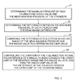
- Figure 2 is a flow diagram example of the inventive method.
- the method comprises a step of determining the maximum pressure and knock value of each cylinder as well as the mean maximum pressure of the cylinders.
- the method also comprises the steps of determining the differences 22 between the maximum pressure of each cylinder and the mean maximum pressure, comparing the differences to a certain deviation range of the mean maximum pressure and the knock value to a certain knock limit value 23 and controlling the duration of the fuel injection of the cylinder in case the difference of a single cylinder exceeds the lower limit of the deviation range and the knock value of the cylinder is below the knock limit value or the difference of a cylinder exceeds the upper limit 24 of the deviation range.
- Figure 3 is an example of the substeps of the inventive method contained in the main steps 23 and 24. In the light of the example it is obvious that this is one way of realizing the main steps and its substeps and there are also other ways of realizing the main steps.
- the differences between the maximum pressure of each cylinder and the mean maximum pressure are compared to a certain deviation range of the mean maximum pressure.
- the deviation range is a range on which the mean maximum pressure is allowed to be. If the difference remains within the deviation range, i.e. the deviation range is not exceeded, there is no need to balance 37 the cylinder. If the difference does not remain within the deviation range, i.e. the deviation range is exceeded, the system checks whether the range has been exceeded below the lower limit 32 of the deviation range. In this case the knock value of the cylinder is compared to a certain knock limit value 35. The magnitude of the knock limit value has been described above. If the knock value is below the knock limit value, the cylinder does not knock and the duration of the fuel injection can be increased 36.
- the cylinder knocks or is close to knocking, and the cylinder is not balanced. If the deviation range has been exceeded above 33 the upper limit, the duration of the fuel injection can be shortened 34. In this case the cylinder can be balanced, even if the cylinder knocked, because the balancing action also decreases the knocking.
- the above description about the calculation of the mean maximum pressure and use of ten cycles also applies to other embodiments of the method.
- the lower and upper limits of the mean deviation range used in the method can be arranged to depend on the average value of the mean maximum pressure. In practice this means e.g. that the mean maximum value varies on the basis of the measurement results and when the middle point of the deviation range is fixed to the mean maximum pressure, also the upper and lower range of the deviation range follow the measurement results.
- the cylinder pressure measurement results depend on the load of the motor, it can be stated that the deviation range can also be arranged to depend on the load of the motor.
- the delay of the fuel injection control is small.
- the cylinders of the motor can also be balanced at higher motor loads. As the cylinders of the motor can be balanced at higher loads as well, the motor runs more smoothly, allowing also an increase of the motor load. In other words, the motors provided with the inventive adjustment system can be driven at higher loads than corresponding motors without the inventive adjustment system.
Landscapes
- Engineering & Computer Science (AREA)
- Chemical & Material Sciences (AREA)
- Combustion & Propulsion (AREA)
- Mechanical Engineering (AREA)
- General Engineering & Computer Science (AREA)
- Combined Controls Of Internal Combustion Engines (AREA)
- Electrical Control Of Air Or Fuel Supplied To Internal-Combustion Engine (AREA)
Description
- The present invention relates to balancing the cylinders of an internal combustion engine. The invention especially relates to internal combustion engines using gas as fuel. In this disclosure the term "gas-burning internal combustion engine" means an engine using only gas as fuel or gas and another fuel, in which case the engine is a so-called dual fuel internal combustion engine. The invention also relates to internal combustion engines using fuels other than gas. The aim of balancing the cylinders is to have each cylinder produce an equal amount of work, taking into account the combustion-technical internal differences between cylinders.
- Fuel is introduced into the cylinders of an internal combustion engine and combusted. The combustion of fuel releases energy which is converted into mechanical movement by means of the piston. Usually the operation of a cylinder is divided into four strokes: intake of fuel, compression stroke, expansion stroke and exhaust removal. The combustion of fuel takes place between the compression and expansion strokes. Together the strokes form a cylinder cycle in which the piston of the cylinder has moved according to the strokes and returned to the initial position. The work done during the stroke is transmitted to the crankshaft. In order to have as smooth a rotation of the crankshaft it is preferable to have each cylinder produce a similar amount of work during the cycle. This is the aim of balancing the cylinders.
- It is known to use measuring the temperature of the engine exhaust gas for balancing the cylinders, especially at low engine loads. (is it measured for each cylinder) The amount of fuel introduced into each cylinder is adjusted on the basis of the measurements. The amount of fuel has an effect on the amount of work the cylinder produces. This method, however, includes a certain delay.
-
US 4706628 discloses a known system for balancing cylinders of an internal combustion engine, wherein differences between maximum pressures of the cylinders and a mean maximum pressure are determined. The differences are compared with an allowable range and duration of the fuel injection is controlled if the difference exceeds out of the range. - When the engine load is higher, engine knock must be taken into account, as knocking can damage the engine. The reason for engine knock is spontaneous ignition of the fuel in the cylinder, causing an undesired method and timing of combustion. Engine knock is often divided into light knock and heavy knock. Light knock describes low fluctuations in the cylinder pressure. Heavy knock describes the highest fluctuations in the cylinder pressure. Light knock is reduced by controlling the ignition timing or the fuel/air ratio. Heavy knock is reduced by reducing the engine load (reducing the amount of fuel) or by even shutting the engine down, if other means are not enough. Knocking is cylinder-specific, so knock adjustment is cylinder-specific as well. Cylinder-specific knock sensors are used for detecting the level of knock. Thus, on highest engine loads the balancing of cylinders is carried out by means of adjustment for light knock. If the engine does not knock, the cylinders are not balanced. Thus, the problems of prior art are that there is a delay in balancing the cylinders and the balancing is necessarily made when the engine is running at highest loads.
- The aim of the invention is to reduce the problems of prior art. The purpose is achieved by means disclosed in the main claim. The system according to the invention comprises cylinder-specific pressure sensors 1 installed in the cylinders for measuring the cylinder pressures and an
adjustment unit 2. The adjustment unit is arranged to define the maximum pressure and knock value of each cylinder as well as the mean maximum pressure of the cylinders as a response to the cylinder pressure measurements and to define the differences between the maximum pressure of each cylinder and the mean maximum pressure. The adjustment unit is also arranged to compare the value to a certain deviation range of the mean maximum pressure and the knock value up to a certain knock limit value and to control the duration of the fuel injection of the cylinder in case the difference of a single cylinder exceeds the lower limit of the deviation range and the knock value of the cylinder is less than the knock limit value or the difference of the cylinders exceeds the upper limit of the deviation range. - In the system the mean maximum pressure is arranged to be calculated from the measured maximum pressures of the cylinders, and the maximum pressure of each cylinder is the average value of the maximum pressure of cycles and that the mean maximum pressure is the average value of the mean maximum pressures of these cycles.
- The upper and lower limits of the mean deviation range are arranged to depend on the load of the motor, and the system is also arranged to reduce the duration of the fuel injection when the upper limit of the deviation range is exceeded and to increase the fuel injection duration when the lower limit of the deviation range is exceeded and the knock value is below the knock limit value.
- In the following the invention is described in more detail by reference to the figures in the drawing, in which
-
Figure 1 illustrates an example of the apparatus according to the invention -
Figure 2 is a flow diagram of the method according to the invention, and -
Figure 3 is a flow diagram example of the substeps of the method according to the invention. -
Figure 1 shows an example of a system according to the invention installed in aninternal combustion engine 3. The system comprises cylinder-specific pressure sensors 1 installed in cylinders 4 for measuring the cylinder pressure and anadjustment unit 2. The pressure curve of a single cylinder follows the strokes during the cycle. The pressure is at its lowest during the intake of fuel and the removal of exhaust gases. The pressure increases during the compression stroke and reaches its maximum during the initial part of the expansion stroke. The measurement data of the cylinder pressure are sent to theadjustment unit 2 receiving the measurement data through areceiving interface 6. - The adjustment unit is arranged to determine the maximum pressure and knock value of each cylinder as well as the mean maximum pressure of the cylinders as a response to the measurements of cylinder pressures. The mean maximum pressure is arranged to be calculated from the measured maximum pressures of the cylinders. The knock value of the cylinder can also be acquired from the pressure sensor of the cylinder whereby no separate knock sensor is needed. The knock value is a value describing whether the cylinder knocks. It is known to use a cylinder-specific value for detecting light knock. If the measured value exceeds the limit of light knock, light knock adjustment is carried out. If the measured value is between zero and the limit value for light knock, there is no knock in the motor.
- The adjustment unit is also arranged to determine the differences between the maximum pressure of each cylinder and the mean maximum pressure and to compare the differences with a certain deviation range of maximum pressure and the knock value to a certain knock limit value. In case the difference of a single cylinder exceeds the lower limit of the deviation range and the knock value of the cylinder is below the knock limit value or the difference of the cylinder exceeds the upper limit of the deviation range, the adjustment unit is arranged to control the duration of the fuel injection of the cylinder. The knock limit value is between zero and the limit for light knocking. The aim of the knock limit value is that the cylinder is not balanced if it knocks or is close to knocking.
- The duration of the fuel injection of the cylinder is arranged to be shortened when the upper limit is exceeded. The duration of the fuel injection is arranged to be increased when the lower limit is exceeded and the knock value is below the knock limit value.
- The used maximum pressure of a cylinder can be arranged to be the mean value of ten cycles of the cylinder. Correspondingly, the mean maximum pressure can be arranged to be the mean value of the average maximum pressure of ten cycles. This allows reducing the effect of random high or low maximum pressures to the control of the fuel injection of the cylinder. The amount of cycles can, of course, be also other than ten cycles. The upper and lower limits of the mean deviation range can be arranged to be dependent of the load of the motor.
- The control unit has a
control interface 7 via which the fuel injection means 5 of each cylinder is controlled. It should be noted that theinterfaces -
Figure 2 is a flow diagram example of the inventive method. As a response to the measurement data of pressure sensors the method comprises a step of determining the maximum pressure and knock value of each cylinder as well as the mean maximum pressure of the cylinders. The method also comprises the steps of determining thedifferences 22 between the maximum pressure of each cylinder and the mean maximum pressure, comparing the differences to a certain deviation range of the mean maximum pressure and the knock value to a certainknock limit value 23 and controlling the duration of the fuel injection of the cylinder in case the difference of a single cylinder exceeds the lower limit of the deviation range and the knock value of the cylinder is below the knock limit value or the difference of a cylinder exceeds theupper limit 24 of the deviation range. -
Figure 3 is an example of the substeps of the inventive method contained in themain steps - In the embodiment of
figure 3 the differences between the maximum pressure of each cylinder and the mean maximum pressure are compared to a certain deviation range of the mean maximum pressure. The deviation range is a range on which the mean maximum pressure is allowed to be. If the difference remains within the deviation range, i.e. the deviation range is not exceeded, there is no need to balance 37 the cylinder. If the difference does not remain within the deviation range, i.e. the deviation range is exceeded, the system checks whether the range has been exceeded below thelower limit 32 of the deviation range. In this case the knock value of the cylinder is compared to a certainknock limit value 35. The magnitude of the knock limit value has been described above. If the knock value is below the knock limit value, the cylinder does not knock and the duration of the fuel injection can be increased 36. If the knock value is above the knock limit value, the cylinder knocks or is close to knocking, and the cylinder is not balanced. If the deviation range has been exceeded above 33 the upper limit, the duration of the fuel injection can be shortened 34. In this case the cylinder can be balanced, even if the cylinder knocked, because the balancing action also decreases the knocking. - The above description about the calculation of the mean maximum pressure and use of ten cycles also applies to other embodiments of the method. The lower and upper limits of the mean deviation range used in the method can be arranged to depend on the average value of the mean maximum pressure. In practice this means e.g. that the mean maximum value varies on the basis of the measurement results and when the middle point of the deviation range is fixed to the mean maximum pressure, also the upper and lower range of the deviation range follow the measurement results. As the cylinder pressure measurement results depend on the load of the motor, it can be stated that the deviation range can also be arranged to depend on the load of the motor.
- As the invention uses maximum pressures of the cylinders, the pressures being direct measurement data from cylinders, the delay of the fuel injection control is small. The cylinders of the motor can also be balanced at higher motor loads. As the cylinders of the motor can be balanced at higher loads as well, the motor runs more smoothly, allowing also an increase of the motor load. In other words, the motors provided with the inventive adjustment system can be driven at higher loads than corresponding motors without the inventive adjustment system.
- In the light of the above description and its examples it is obvious that the embodiment according to the invention can be realized in a number of ways. It is obvious that the invention is not limited to the examples mentioned here, but that the invention can be realized by a number of different embodiments.
- Thus, any inventive embodiment can be carried out within the scope of the invention.
Claims (7)
- An adjustment system for balancing cylinders of an internal combustion engine, which system comprises cylinder-specific pressure sensors (1) installable in the cylinders for measuring cylinder pressures and an adjustment unit (2) arranged to determine a maximum pressure and knock value of each cylinder, wherein the adjustment unit is further arranged to determine a mean maximum pressure of the cylinders as a response to measurements of cylinder pressures,
determine differences between the maximum pressure of each cylinder and the mean maximum pressure,
compare the differences to a certain deviation range of the mean maximum pressure and the knock value to a certain knock limit value,
control duration of the fuel injection of the cylinder in case the difference of one of the cylinders exceeds the lower limit of the deviation range and the knock value of the cylinder is below the knock limit value, and in case the difference of one of the cylinders exceeds the upper limit of the deviation range
wherein mean maximum pressure is arranged to be calculated from the measured maximum pressures of the cylinders, and
the maximum pressure of each cylinder is the average value of the maximum pressure of cycles and that the mean maximum pressure is the average value of the mean maximum pressures of these cycles,
wherein the upper and lower limits of the mean deviation range are arranged to depend on the load of the motor, and the system
is arranged to reduce the duration of the fuel injection when the upper limit of the deviation range is exceeded and to increase the fuel injection duration when the lower limit of the deviation range is exceeded and the knock value is below the knock limit value. - A system according to claim 2, characterized in that the knock limit value is arranged to be between zero and the limit value of light knock.
- A system according to claim 1 or 2, characterized in that the adjustment unit comprises an interface for receiving cylinder-specific pressure data and another interface for cylinder-specifically controlling the duration of the fuel injection.
- A system according to claim 3, characterized in that is it connected to an internal combustion engine.
- A system according to claim 3, characterized in that the used fuel is gas.
- A method for balancing cylinders of an internal combustion engine, wherein as a response to measurements of cylinder pressures the method comprises steps of:determining a maximum pressure and knock value of each cylinder as well as a mean maximum pressure of the cylinders,determining differences between the maximum pressure of each cylinder and the mean maximum pressure,comparing the differences to a certain deviation range of the mean maximum pressure and the knock value to a certain knock limit value,controlling duration of the fuel injection of the cylinder in case the difference of one of the cylinders exceeds the lower limit of the deviation range and the knock value of the cylinder is below the knock limit value ,and in case the difference of one of the cylinders exceeds the upper limit of the deviation range,wherein the mean maximum pressure is arranged to be calculated from the measured maximum pressures of the cylinders,andthe maximum pressure of each cylinder is the average value of the maximum pressure of cycles and that the mean maximum pressure is the average value of the mean maximum pressures of these cycles,wherein the upper and lower limits of the mean deviation range are arranged to depend on the load of the motor, and the methodis arranged to reduce the duration of the fuel injection when the upper limit of the deviation range is exceeded and to increase the fuel injection duration when the lower limit of the deviation range is exceeded and the knock value is below the knock limit value.
- A method according to claim 6, characterized in that the knock limit value is arranged to be between zero and the limit value of light knock.
Applications Claiming Priority (2)
| Application Number | Priority Date | Filing Date | Title |
|---|---|---|---|
| FI20085264A FI121031B (en) | 2008-03-31 | 2008-03-31 | Control system and method for balancing the cylinders in a gas-powered internal combustion engine |
| PCT/FI2009/050229 WO2009122012A1 (en) | 2008-03-31 | 2009-03-25 | An adjustment system for balancing the cylinders of a gas -burning internal combustion engine |
Publications (2)
| Publication Number | Publication Date |
|---|---|
| EP2262999A1 EP2262999A1 (en) | 2010-12-22 |
| EP2262999B1 true EP2262999B1 (en) | 2016-11-30 |
Family
ID=39269556
Family Applications (1)
| Application Number | Title | Priority Date | Filing Date |
|---|---|---|---|
| EP09726938.5A Active EP2262999B1 (en) | 2008-03-31 | 2009-03-25 | An adjustment system for balancing the cylinders of a gas -burning internal combustion engine |
Country Status (5)
| Country | Link |
|---|---|
| US (1) | US7957889B2 (en) |
| EP (1) | EP2262999B1 (en) |
| KR (1) | KR101541942B1 (en) |
| FI (1) | FI121031B (en) |
| WO (1) | WO2009122012A1 (en) |
Cited By (1)
| Publication number | Priority date | Publication date | Assignee | Title |
|---|---|---|---|---|
| US11131265B2 (en) | 2018-06-06 | 2021-09-28 | Caterpillar Motoren GbmH & Co. KG | Knock mitigation and cylinder balancing in an internal combustion engine |
Families Citing this family (20)
| Publication number | Priority date | Publication date | Assignee | Title |
|---|---|---|---|---|
| JP4688916B2 (en) * | 2008-10-01 | 2011-05-25 | 川崎重工業株式会社 | Gas engine control device |
| AT511001B1 (en) * | 2011-01-18 | 2013-11-15 | Ge Jenbacher Gmbh & Co Ohg | METHOD FOR OPERATING A COMBUSTION ENGINE THROUGHOUT AT LEAST TWO CYLINDER |
| AT513359B1 (en) | 2012-08-17 | 2014-07-15 | Ge Jenbacher Gmbh & Co Og | Method for operating an internal combustion engine |
| AT513139B1 (en) * | 2012-08-17 | 2014-02-15 | Ge Jenbacher Gmbh & Co Og | Method for operating an internal combustion engine |
| JP6128975B2 (en) * | 2013-06-11 | 2017-05-17 | ヤンマー株式会社 | Gas engine |
| EP2907993B1 (en) * | 2014-02-13 | 2019-11-06 | Caterpillar Motoren GmbH & Co. KG | Method for balancing cylinders of an internal combustion engine |
| EP2915987B1 (en) * | 2014-03-07 | 2016-12-21 | Caterpillar Motoren GmbH & Co. KG | Evaluating gaseous fuel admission valve operability |
| CN105020033B (en) * | 2014-04-29 | 2017-10-13 | 长城汽车股份有限公司 | Balance control method, system and automobile between the cylinder of dual fuel engine |
| DE102014007009B4 (en) * | 2014-05-13 | 2018-01-18 | Mtu Friedrichshafen Gmbh | Engine monitoring by means of cylinder-specific pressure sensors excellently with lean gas engines with purged prechamber |
| EP3283748B1 (en) | 2015-04-14 | 2023-07-26 | Woodward, Inc. | Combustion pressure feedback based engine control with variable resolution sampling windows |
| US10393609B2 (en) * | 2015-07-02 | 2019-08-27 | Ai Alpine Us Bidco Inc. | System and method for detection of changes to compression ratio and peak firing pressure of an engine |
| DE102015218835B3 (en) * | 2015-09-30 | 2016-11-24 | Continental Automotive Gmbh | Method and apparatus for injecting gaseous fuel |
| US9822727B2 (en) | 2015-10-29 | 2017-11-21 | General Electric Company | Method and systems for adjusting engine cylinder operation based on a knock sensor output |
| DK3267017T3 (en) | 2016-07-05 | 2025-01-02 | Wingd Ag | METHOD FOR OPERATING A DUAL-FUEL LARGE DIESEL ENGINE AND LARGE DIESEL ENGINE |
| US10408158B2 (en) | 2016-09-30 | 2019-09-10 | Ge Global Sourcing Llc | Differential cylinder balancing for internal combustion engine |
| US11236685B2 (en) * | 2016-09-30 | 2022-02-01 | Transportation Ip Holdings, Llc | Differential cylinder balancing for internal combustion engine |
| JP6965614B2 (en) * | 2017-07-21 | 2021-11-10 | トヨタ自動車株式会社 | Internal combustion engine control device |
| US10934965B2 (en) | 2019-04-05 | 2021-03-02 | Woodward, Inc. | Auto-ignition control in a combustion engine |
| CN114542297B (en) * | 2022-03-18 | 2023-01-06 | 潍柴动力股份有限公司 | Method and system for correcting fuel injection quantity of electronically controlled unit pump |
| CN116641793B (en) * | 2023-06-08 | 2025-10-28 | 长城汽车股份有限公司 | Engine abnormality detection method, device, vehicle and storage medium |
Citations (1)
| Publication number | Priority date | Publication date | Assignee | Title |
|---|---|---|---|---|
| US4706628A (en) * | 1986-12-29 | 1987-11-17 | General Motors Corporation | Engine combustion control responsive to location and magnitude of peak combustion pressure |
Family Cites Families (14)
| Publication number | Priority date | Publication date | Assignee | Title |
|---|---|---|---|---|
| US5450829A (en) * | 1994-05-03 | 1995-09-19 | Servojet Products International | Electronically controlled pilot fuel injection of compression ignition engines |
| JPH09209814A (en) * | 1996-02-05 | 1997-08-12 | Unisia Jecs Corp | Control device for internal combustion engine |
| US20020195086A1 (en) * | 1997-12-16 | 2002-12-26 | Beck N. John | Cylinder pressure based optimization control for compression ignition engines |
| US6209520B1 (en) * | 1999-06-15 | 2001-04-03 | Ilya V. Kolmanovsky | Method and apparatus for cylinder balancing |
| US6516780B2 (en) * | 2000-11-13 | 2003-02-11 | Siemens Vdo Automotive Corporation | System and method for optimizing engine performance |
| EP2479412A3 (en) * | 2001-03-30 | 2014-08-13 | Mitsubishi Heavy Industries, Ltd. | Apparatus and method of combustion diagnosis/control in internal combustion engine |
| GB0112338D0 (en) | 2001-05-21 | 2001-07-11 | Ricardo Consulting Eng | Improved engine management |
| US6557528B2 (en) * | 2001-08-30 | 2003-05-06 | Caterpillar Inc. | Method of controlling detonation in an internal combustion engine |
| JP4155807B2 (en) * | 2002-12-03 | 2008-09-24 | 富士通テン株式会社 | Knock detection device |
| DE10307367A1 (en) | 2003-02-21 | 2004-09-09 | B + V Industrietechnik Gmbh | Regulating gas-powered engines involves measuring combustion pressure in each cylinder, controlling fuel feed depending on pressure evaluation carried out immediately after pressure value measurement |
| US6981488B2 (en) * | 2003-09-16 | 2006-01-03 | Southwest Research Institute | Internal combustion engine cylinder-to-cylinder balancing with balanced air-fuel ratios |
| US7007661B2 (en) | 2004-01-27 | 2006-03-07 | Woodward Governor Company | Method and apparatus for controlling micro pilot fuel injection to minimize NOx and UHC emissions |
| FI119395B (en) | 2004-03-15 | 2008-10-31 | Waertsilae Finland Oy | Adaptive load balancing system |
| US7823563B2 (en) * | 2008-05-08 | 2010-11-02 | Ford Global Technologies, Llc | Cylinder-by-cylinder balancing of combustion timing in HCCI engines |
-
2008
- 2008-03-31 FI FI20085264A patent/FI121031B/en not_active IP Right Cessation
-
2009
- 2009-03-25 EP EP09726938.5A patent/EP2262999B1/en active Active
- 2009-03-25 US US12/935,534 patent/US7957889B2/en active Active
- 2009-03-25 KR KR1020107022844A patent/KR101541942B1/en active Active
- 2009-03-25 WO PCT/FI2009/050229 patent/WO2009122012A1/en not_active Ceased
Patent Citations (1)
| Publication number | Priority date | Publication date | Assignee | Title |
|---|---|---|---|---|
| US4706628A (en) * | 1986-12-29 | 1987-11-17 | General Motors Corporation | Engine combustion control responsive to location and magnitude of peak combustion pressure |
Cited By (1)
| Publication number | Priority date | Publication date | Assignee | Title |
|---|---|---|---|---|
| US11131265B2 (en) | 2018-06-06 | 2021-09-28 | Caterpillar Motoren GbmH & Co. KG | Knock mitigation and cylinder balancing in an internal combustion engine |
Also Published As
| Publication number | Publication date |
|---|---|
| EP2262999A1 (en) | 2010-12-22 |
| FI20085264A0 (en) | 2008-03-31 |
| KR20110008176A (en) | 2011-01-26 |
| WO2009122012A1 (en) | 2009-10-08 |
| US20110017173A1 (en) | 2011-01-27 |
| KR101541942B1 (en) | 2015-08-04 |
| FI20085264L (en) | 2009-10-01 |
| US7957889B2 (en) | 2011-06-07 |
| FI121031B (en) | 2010-06-15 |
Similar Documents
| Publication | Publication Date | Title |
|---|---|---|
| US7957889B2 (en) | Adjustment system for balancing the cylinders of a gas-burning internal combustion engine | |
| EP2700804B1 (en) | Gas engine, gas engine control apparatus, and gas engine control method | |
| US9140229B2 (en) | Knocking control system for gas engine | |
| JP6262957B2 (en) | Operation method of internal combustion engine | |
| JP2014037835A (en) | Operation method for internal combustion engine | |
| EP2592257A1 (en) | Control device for internal combustion engine | |
| RU2494270C2 (en) | Method and system for diesel engine cylinders balancing | |
| US20150226642A1 (en) | In-cylinder pressure detection device for internal combustion engine | |
| KR101510921B1 (en) | System for regulating pilot fuel supply in a combustion engine | |
| US20150219026A1 (en) | In-cylinder pressure detection device for internal combustion engine | |
| JP2013147948A (en) | Internal combustion engine control device | |
| US7051712B2 (en) | Method for computing an ignition angle of an internal combustion engine | |
| KR102241277B1 (en) | A method of operating an internal combustion piston engine, a control system for controlling the operation of an internal combustion piston engine, and an internal combustion piston engine | |
| JP4830986B2 (en) | Control device for internal combustion engine | |
| JP2011157852A (en) | Control device of internal combustion engine | |
| JP2010174705A (en) | Control device for internal combustion engine | |
| EP3225823B1 (en) | Ship propulsion system | |
| JP2015158163A (en) | Spark-ignition internal combustion engine controller | |
| JP6815534B2 (en) | Internal combustion engine control device | |
| EP3669060A1 (en) | A method of controlling combustion of fuel in a multi-cylinder internal combustion engine and a computer control system configured to control combustion process in a multi-cylinder internal combustion piston engine | |
| CN107949692A (en) | For determining the method and control system of the offset related with crank angular measurement | |
| JPH04237845A (en) | Diesel engine fuel injection timing control device | |
| JP2021124071A (en) | Control device of internal combustion engine | |
| za Kaleli et al. | Self Tuning Controller for Reducing Cycle to Cycle Variations in SI Engine | |
| JP2016011596A (en) | Internal combustion engine combustion pressure detection method and internal combustion engine combustion pressure detector |
Legal Events
| Date | Code | Title | Description |
|---|---|---|---|
| PUAI | Public reference made under article 153(3) epc to a published international application that has entered the european phase |
Free format text: ORIGINAL CODE: 0009012 |
|
| 17P | Request for examination filed |
Effective date: 20100930 |
|
| AK | Designated contracting states |
Kind code of ref document: A1 Designated state(s): AT BE BG CH CY CZ DE DK EE ES FI FR GB GR HR HU IE IS IT LI LT LU LV MC MK MT NL NO PL PT RO SE SI SK TR |
|
| AX | Request for extension of the european patent |
Extension state: AL BA RS |
|
| DAX | Request for extension of the european patent (deleted) | ||
| 17Q | First examination report despatched |
Effective date: 20151211 |
|
| GRAP | Despatch of communication of intention to grant a patent |
Free format text: ORIGINAL CODE: EPIDOSNIGR1 |
|
| INTG | Intention to grant announced |
Effective date: 20160614 |
|
| GRAS | Grant fee paid |
Free format text: ORIGINAL CODE: EPIDOSNIGR3 |
|
| GRAA | (expected) grant |
Free format text: ORIGINAL CODE: 0009210 |
|
| AK | Designated contracting states |
Kind code of ref document: B1 Designated state(s): AT BE BG CH CY CZ DE DK EE ES FI FR GB GR HR HU IE IS IT LI LT LU LV MC MK MT NL NO PL PT RO SE SI SK TR |
|
| REG | Reference to a national code |
Ref country code: CH Ref legal event code: EP Ref country code: GB Ref legal event code: FG4D |
|
| REG | Reference to a national code |
Ref country code: AT Ref legal event code: REF Ref document number: 850031 Country of ref document: AT Kind code of ref document: T Effective date: 20161215 |
|
| REG | Reference to a national code |
Ref country code: IE Ref legal event code: FG4D |
|
| REG | Reference to a national code |
Ref country code: DE Ref legal event code: R096 Ref document number: 602009042773 Country of ref document: DE |
|
| PG25 | Lapsed in a contracting state [announced via postgrant information from national office to epo] |
Ref country code: LV Free format text: LAPSE BECAUSE OF FAILURE TO SUBMIT A TRANSLATION OF THE DESCRIPTION OR TO PAY THE FEE WITHIN THE PRESCRIBED TIME-LIMIT Effective date: 20161130 |
|
| REG | Reference to a national code |
Ref country code: LT Ref legal event code: MG4D |
|
| REG | Reference to a national code |
Ref country code: NL Ref legal event code: MP Effective date: 20161130 |
|
| PG25 | Lapsed in a contracting state [announced via postgrant information from national office to epo] |
Ref country code: GR Free format text: LAPSE BECAUSE OF FAILURE TO SUBMIT A TRANSLATION OF THE DESCRIPTION OR TO PAY THE FEE WITHIN THE PRESCRIBED TIME-LIMIT Effective date: 20170301 Ref country code: NO Free format text: LAPSE BECAUSE OF FAILURE TO SUBMIT A TRANSLATION OF THE DESCRIPTION OR TO PAY THE FEE WITHIN THE PRESCRIBED TIME-LIMIT Effective date: 20170228 Ref country code: LT Free format text: LAPSE BECAUSE OF FAILURE TO SUBMIT A TRANSLATION OF THE DESCRIPTION OR TO PAY THE FEE WITHIN THE PRESCRIBED TIME-LIMIT Effective date: 20161130 Ref country code: SE Free format text: LAPSE BECAUSE OF FAILURE TO SUBMIT A TRANSLATION OF THE DESCRIPTION OR TO PAY THE FEE WITHIN THE PRESCRIBED TIME-LIMIT Effective date: 20161130 |
|
| PG25 | Lapsed in a contracting state [announced via postgrant information from national office to epo] |
Ref country code: HR Free format text: LAPSE BECAUSE OF FAILURE TO SUBMIT A TRANSLATION OF THE DESCRIPTION OR TO PAY THE FEE WITHIN THE PRESCRIBED TIME-LIMIT Effective date: 20161130 Ref country code: ES Free format text: LAPSE BECAUSE OF FAILURE TO SUBMIT A TRANSLATION OF THE DESCRIPTION OR TO PAY THE FEE WITHIN THE PRESCRIBED TIME-LIMIT Effective date: 20161130 Ref country code: PL Free format text: LAPSE BECAUSE OF FAILURE TO SUBMIT A TRANSLATION OF THE DESCRIPTION OR TO PAY THE FEE WITHIN THE PRESCRIBED TIME-LIMIT Effective date: 20161130 Ref country code: PT Free format text: LAPSE BECAUSE OF FAILURE TO SUBMIT A TRANSLATION OF THE DESCRIPTION OR TO PAY THE FEE WITHIN THE PRESCRIBED TIME-LIMIT Effective date: 20170330 Ref country code: FI Free format text: LAPSE BECAUSE OF FAILURE TO SUBMIT A TRANSLATION OF THE DESCRIPTION OR TO PAY THE FEE WITHIN THE PRESCRIBED TIME-LIMIT Effective date: 20161130 |
|
| PG25 | Lapsed in a contracting state [announced via postgrant information from national office to epo] |
Ref country code: NL Free format text: LAPSE BECAUSE OF FAILURE TO SUBMIT A TRANSLATION OF THE DESCRIPTION OR TO PAY THE FEE WITHIN THE PRESCRIBED TIME-LIMIT Effective date: 20161130 |
|
| PG25 | Lapsed in a contracting state [announced via postgrant information from national office to epo] |
Ref country code: DK Free format text: LAPSE BECAUSE OF FAILURE TO SUBMIT A TRANSLATION OF THE DESCRIPTION OR TO PAY THE FEE WITHIN THE PRESCRIBED TIME-LIMIT Effective date: 20161130 Ref country code: RO Free format text: LAPSE BECAUSE OF FAILURE TO SUBMIT A TRANSLATION OF THE DESCRIPTION OR TO PAY THE FEE WITHIN THE PRESCRIBED TIME-LIMIT Effective date: 20161130 Ref country code: CZ Free format text: LAPSE BECAUSE OF FAILURE TO SUBMIT A TRANSLATION OF THE DESCRIPTION OR TO PAY THE FEE WITHIN THE PRESCRIBED TIME-LIMIT Effective date: 20161130 Ref country code: EE Free format text: LAPSE BECAUSE OF FAILURE TO SUBMIT A TRANSLATION OF THE DESCRIPTION OR TO PAY THE FEE WITHIN THE PRESCRIBED TIME-LIMIT Effective date: 20161130 Ref country code: SK Free format text: LAPSE BECAUSE OF FAILURE TO SUBMIT A TRANSLATION OF THE DESCRIPTION OR TO PAY THE FEE WITHIN THE PRESCRIBED TIME-LIMIT Effective date: 20161130 |
|
| PG25 | Lapsed in a contracting state [announced via postgrant information from national office to epo] |
Ref country code: BG Free format text: LAPSE BECAUSE OF FAILURE TO SUBMIT A TRANSLATION OF THE DESCRIPTION OR TO PAY THE FEE WITHIN THE PRESCRIBED TIME-LIMIT Effective date: 20170228 Ref country code: BE Free format text: LAPSE BECAUSE OF FAILURE TO SUBMIT A TRANSLATION OF THE DESCRIPTION OR TO PAY THE FEE WITHIN THE PRESCRIBED TIME-LIMIT Effective date: 20161130 Ref country code: IT Free format text: LAPSE BECAUSE OF FAILURE TO SUBMIT A TRANSLATION OF THE DESCRIPTION OR TO PAY THE FEE WITHIN THE PRESCRIBED TIME-LIMIT Effective date: 20161130 |
|
| REG | Reference to a national code |
Ref country code: DE Ref legal event code: R097 Ref document number: 602009042773 Country of ref document: DE |
|
| PLBE | No opposition filed within time limit |
Free format text: ORIGINAL CODE: 0009261 |
|
| STAA | Information on the status of an ep patent application or granted ep patent |
Free format text: STATUS: NO OPPOSITION FILED WITHIN TIME LIMIT |
|
| REG | Reference to a national code |
Ref country code: CH Ref legal event code: PL |
|
| 26N | No opposition filed |
Effective date: 20170831 |
|
| GBPC | Gb: european patent ceased through non-payment of renewal fee |
Effective date: 20170325 |
|
| PG25 | Lapsed in a contracting state [announced via postgrant information from national office to epo] |
Ref country code: SI Free format text: LAPSE BECAUSE OF FAILURE TO SUBMIT A TRANSLATION OF THE DESCRIPTION OR TO PAY THE FEE WITHIN THE PRESCRIBED TIME-LIMIT Effective date: 20161130 Ref country code: MC Free format text: LAPSE BECAUSE OF FAILURE TO SUBMIT A TRANSLATION OF THE DESCRIPTION OR TO PAY THE FEE WITHIN THE PRESCRIBED TIME-LIMIT Effective date: 20161130 |
|
| REG | Reference to a national code |
Ref country code: IE Ref legal event code: MM4A |
|
| REG | Reference to a national code |
Ref country code: FR Ref legal event code: ST Effective date: 20171130 |
|
| PG25 | Lapsed in a contracting state [announced via postgrant information from national office to epo] |
Ref country code: LU Free format text: LAPSE BECAUSE OF NON-PAYMENT OF DUE FEES Effective date: 20170325 Ref country code: FR Free format text: LAPSE BECAUSE OF NON-PAYMENT OF DUE FEES Effective date: 20170331 |
|
| PG25 | Lapsed in a contracting state [announced via postgrant information from national office to epo] |
Ref country code: IE Free format text: LAPSE BECAUSE OF NON-PAYMENT OF DUE FEES Effective date: 20170325 Ref country code: GB Free format text: LAPSE BECAUSE OF NON-PAYMENT OF DUE FEES Effective date: 20170325 Ref country code: CH Free format text: LAPSE BECAUSE OF NON-PAYMENT OF DUE FEES Effective date: 20170331 Ref country code: LI Free format text: LAPSE BECAUSE OF NON-PAYMENT OF DUE FEES Effective date: 20170331 |
|
| PG25 | Lapsed in a contracting state [announced via postgrant information from national office to epo] |
Ref country code: MT Free format text: LAPSE BECAUSE OF NON-PAYMENT OF DUE FEES Effective date: 20170325 |
|
| PG25 | Lapsed in a contracting state [announced via postgrant information from national office to epo] |
Ref country code: HU Free format text: LAPSE BECAUSE OF FAILURE TO SUBMIT A TRANSLATION OF THE DESCRIPTION OR TO PAY THE FEE WITHIN THE PRESCRIBED TIME-LIMIT; INVALID AB INITIO Effective date: 20090325 |
|
| REG | Reference to a national code |
Ref country code: AT Ref legal event code: UEP Ref document number: 850031 Country of ref document: AT Kind code of ref document: T Effective date: 20161130 |
|
| PG25 | Lapsed in a contracting state [announced via postgrant information from national office to epo] |
Ref country code: CY Free format text: LAPSE BECAUSE OF NON-PAYMENT OF DUE FEES Effective date: 20161130 |
|
| PG25 | Lapsed in a contracting state [announced via postgrant information from national office to epo] |
Ref country code: MK Free format text: LAPSE BECAUSE OF FAILURE TO SUBMIT A TRANSLATION OF THE DESCRIPTION OR TO PAY THE FEE WITHIN THE PRESCRIBED TIME-LIMIT Effective date: 20161130 |
|
| PG25 | Lapsed in a contracting state [announced via postgrant information from national office to epo] |
Ref country code: TR Free format text: LAPSE BECAUSE OF FAILURE TO SUBMIT A TRANSLATION OF THE DESCRIPTION OR TO PAY THE FEE WITHIN THE PRESCRIBED TIME-LIMIT Effective date: 20161130 |
|
| PG25 | Lapsed in a contracting state [announced via postgrant information from national office to epo] |
Ref country code: IS Free format text: LAPSE BECAUSE OF FAILURE TO SUBMIT A TRANSLATION OF THE DESCRIPTION OR TO PAY THE FEE WITHIN THE PRESCRIBED TIME-LIMIT Effective date: 20170330 |
|
| PGFP | Annual fee paid to national office [announced via postgrant information from national office to epo] |
Ref country code: DE Payment date: 20260319 Year of fee payment: 18 |
|
| PGFP | Annual fee paid to national office [announced via postgrant information from national office to epo] |
Ref country code: AT Payment date: 20260320 Year of fee payment: 18 |