EP2261896A1 - Performance-related information output device, system provided with performance-related information output device, and electronic musical instrument - Google Patents
Performance-related information output device, system provided with performance-related information output device, and electronic musical instrument Download PDFInfo
- Publication number
- EP2261896A1 EP2261896A1 EP09802994A EP09802994A EP2261896A1 EP 2261896 A1 EP2261896 A1 EP 2261896A1 EP 09802994 A EP09802994 A EP 09802994A EP 09802994 A EP09802994 A EP 09802994A EP 2261896 A1 EP2261896 A1 EP 2261896A1
- Authority
- EP
- European Patent Office
- Prior art keywords
- musical performance
- section
- audio signal
- related information
- information
- Prior art date
- Legal status (The legal status is an assumption and is not a legal conclusion. Google has not performed a legal analysis and makes no representation as to the accuracy of the status listed.)
- Granted
Links
Images


Classifications
-
- G—PHYSICS
- G10—MUSICAL INSTRUMENTS; ACOUSTICS
- G10H—ELECTROPHONIC MUSICAL INSTRUMENTS; INSTRUMENTS IN WHICH THE TONES ARE GENERATED BY ELECTROMECHANICAL MEANS OR ELECTRONIC GENERATORS, OR IN WHICH THE TONES ARE SYNTHESISED FROM A DATA STORE
- G10H1/00—Details of electrophonic musical instruments
- G10H1/02—Means for controlling the tone frequencies, e.g. attack or decay; Means for producing special musical effects, e.g. vibratos or glissandos
- G10H1/06—Circuits for establishing the harmonic content of tones, or other arrangements for changing the tone colour
-
- G—PHYSICS
- G10—MUSICAL INSTRUMENTS; ACOUSTICS
- G10H—ELECTROPHONIC MUSICAL INSTRUMENTS; INSTRUMENTS IN WHICH THE TONES ARE GENERATED BY ELECTROMECHANICAL MEANS OR ELECTRONIC GENERATORS, OR IN WHICH THE TONES ARE SYNTHESISED FROM A DATA STORE
- G10H1/00—Details of electrophonic musical instruments
- G10H1/0033—Recording/reproducing or transmission of music for electrophonic musical instruments
- G10H1/0041—Recording/reproducing or transmission of music for electrophonic musical instruments in coded form
- G10H1/0058—Transmission between separate instruments or between individual components of a musical system
- G10H1/0066—Transmission between separate instruments or between individual components of a musical system using a MIDI interface
-
- G—PHYSICS
- G10—MUSICAL INSTRUMENTS; ACOUSTICS
- G10H—ELECTROPHONIC MUSICAL INSTRUMENTS; INSTRUMENTS IN WHICH THE TONES ARE GENERATED BY ELECTROMECHANICAL MEANS OR ELECTRONIC GENERATORS, OR IN WHICH THE TONES ARE SYNTHESISED FROM A DATA STORE
- G10H1/00—Details of electrophonic musical instruments
- G10H1/36—Accompaniment arrangements
- G10H1/40—Rhythm
-
- G—PHYSICS
- G10—MUSICAL INSTRUMENTS; ACOUSTICS
- G10H—ELECTROPHONIC MUSICAL INSTRUMENTS; INSTRUMENTS IN WHICH THE TONES ARE GENERATED BY ELECTROMECHANICAL MEANS OR ELECTRONIC GENERATORS, OR IN WHICH THE TONES ARE SYNTHESISED FROM A DATA STORE
- G10H3/00—Instruments in which the tones are generated by electromechanical means
- G10H3/12—Instruments in which the tones are generated by electromechanical means using mechanical resonant generators, e.g. strings or percussive instruments, the tones of which are picked up by electromechanical transducers, the electrical signals being further manipulated or amplified and subsequently converted to sound by a loudspeaker or equivalent instrument
- G10H3/14—Instruments in which the tones are generated by electromechanical means using mechanical resonant generators, e.g. strings or percussive instruments, the tones of which are picked up by electromechanical transducers, the electrical signals being further manipulated or amplified and subsequently converted to sound by a loudspeaker or equivalent instrument using mechanically actuated vibrators with pick-up means
- G10H3/18—Instruments in which the tones are generated by electromechanical means using mechanical resonant generators, e.g. strings or percussive instruments, the tones of which are picked up by electromechanical transducers, the electrical signals being further manipulated or amplified and subsequently converted to sound by a loudspeaker or equivalent instrument using mechanically actuated vibrators with pick-up means using a string, e.g. electric guitar
- G10H3/186—Means for processing the signal picked up from the strings
- G10H3/188—Means for processing the signal picked up from the strings for converting the signal to digital format
-
- G—PHYSICS
- G10—MUSICAL INSTRUMENTS; ACOUSTICS
- G10H—ELECTROPHONIC MUSICAL INSTRUMENTS; INSTRUMENTS IN WHICH THE TONES ARE GENERATED BY ELECTROMECHANICAL MEANS OR ELECTRONIC GENERATORS, OR IN WHICH THE TONES ARE SYNTHESISED FROM A DATA STORE
- G10H2220/00—Input/output interfacing specifically adapted for electrophonic musical tools or instruments
- G10H2220/155—User input interfaces for electrophonic musical instruments
- G10H2220/265—Key design details; Special characteristics of individual keys of a keyboard; Key-like musical input devices, e.g. finger sensors, pedals, potentiometers, selectors
- G10H2220/275—Switching mechanism or sensor details of individual keys, e.g. details of key contacts, hall effect or piezoelectric sensors used for key position or movement sensing purposes; Mounting thereof
- G10H2220/295—Switch matrix, e.g. contact array common to several keys, the actuated keys being identified by the rows and columns in contact
- G10H2220/301—Fret-like switch array arrangements for guitar necks
-
- G—PHYSICS
- G10—MUSICAL INSTRUMENTS; ACOUSTICS
- G10H—ELECTROPHONIC MUSICAL INSTRUMENTS; INSTRUMENTS IN WHICH THE TONES ARE GENERATED BY ELECTROMECHANICAL MEANS OR ELECTRONIC GENERATORS, OR IN WHICH THE TONES ARE SYNTHESISED FROM A DATA STORE
- G10H2220/00—Input/output interfacing specifically adapted for electrophonic musical tools or instruments
- G10H2220/155—User input interfaces for electrophonic musical instruments
- G10H2220/391—Angle sensing for musical purposes, using data from a gyroscope, gyrometer or other angular velocity or angular movement sensing device
-
- G—PHYSICS
- G10—MUSICAL INSTRUMENTS; ACOUSTICS
- G10H—ELECTROPHONIC MUSICAL INSTRUMENTS; INSTRUMENTS IN WHICH THE TONES ARE GENERATED BY ELECTROMECHANICAL MEANS OR ELECTRONIC GENERATORS, OR IN WHICH THE TONES ARE SYNTHESISED FROM A DATA STORE
- G10H2240/00—Data organisation or data communication aspects, specifically adapted for electrophonic musical tools or instruments
- G10H2240/011—Files or data streams containing coded musical information, e.g. for transmission
- G10H2240/031—File merging MIDI, i.e. merging or mixing a MIDI-like file or stream with a non-MIDI file or stream, e.g. audio or video
-
- G—PHYSICS
- G10—MUSICAL INSTRUMENTS; ACOUSTICS
- G10H—ELECTROPHONIC MUSICAL INSTRUMENTS; INSTRUMENTS IN WHICH THE TONES ARE GENERATED BY ELECTROMECHANICAL MEANS OR ELECTRONIC GENERATORS, OR IN WHICH THE TONES ARE SYNTHESISED FROM A DATA STORE
- G10H2240/00—Data organisation or data communication aspects, specifically adapted for electrophonic musical tools or instruments
- G10H2240/171—Transmission of musical instrument data, control or status information; Transmission, remote access or control of music data for electrophonic musical instruments
- G10H2240/201—Physical layer or hardware aspects of transmission to or from an electrophonic musical instrument, e.g. voltage levels, bit streams, code words or symbols over a physical link connecting network nodes or instruments
- G10H2240/205—Synchronous transmission of an analog or digital signal, e.g. according to a specific intrinsic timing, or according to a separate clock
-
- G—PHYSICS
- G10—MUSICAL INSTRUMENTS; ACOUSTICS
- G10H—ELECTROPHONIC MUSICAL INSTRUMENTS; INSTRUMENTS IN WHICH THE TONES ARE GENERATED BY ELECTROMECHANICAL MEANS OR ELECTRONIC GENERATORS, OR IN WHICH THE TONES ARE SYNTHESISED FROM A DATA STORE
- G10H2240/00—Data organisation or data communication aspects, specifically adapted for electrophonic musical tools or instruments
- G10H2240/171—Transmission of musical instrument data, control or status information; Transmission, remote access or control of music data for electrophonic musical instruments
- G10H2240/201—Physical layer or hardware aspects of transmission to or from an electrophonic musical instrument, e.g. voltage levels, bit streams, code words or symbols over a physical link connecting network nodes or instruments
- G10H2240/215—Spread spectrum, i.e. transmission on a bandwidth considerably larger than the frequency content of the original information
-
- G—PHYSICS
- G10—MUSICAL INSTRUMENTS; ACOUSTICS
- G10H—ELECTROPHONIC MUSICAL INSTRUMENTS; INSTRUMENTS IN WHICH THE TONES ARE GENERATED BY ELECTROMECHANICAL MEANS OR ELECTRONIC GENERATORS, OR IN WHICH THE TONES ARE SYNTHESISED FROM A DATA STORE
- G10H2240/00—Data organisation or data communication aspects, specifically adapted for electrophonic musical tools or instruments
- G10H2240/171—Transmission of musical instrument data, control or status information; Transmission, remote access or control of music data for electrophonic musical instruments
- G10H2240/201—Physical layer or hardware aspects of transmission to or from an electrophonic musical instrument, e.g. voltage levels, bit streams, code words or symbols over a physical link connecting network nodes or instruments
- G10H2240/225—Frequency division multiplexing
Definitions
- the manipulating section 30 receives a manipulation input of a user and outputs a manipulation signal according to the manipulation input to the control unit 31.
- the manipulating section 30 is a start button which instructs reproduction of the audio signal, a stop button which instructs stoppage of the audio signal, or the like.
- the reproducing device 3 delays and outputs the audio signal later than the musical performance information by the delay time, it is possible to output the audio signal and the musical performance information at the same time (that is, synchronously). Therefore, the reproducing device 3 can display the code information or fingering information based on the musical performance information on the monitor 37 at the same time with emission of sound according to the musical performance information. As a result, the audience can listen to emitted sound while confirming the code information or fingering information through the monitor 37.
- Fig. 7 is an appearance diagram showing the appearance of another guitar with a musical performance information output device.
- the acoustic guitar 4 has been described as an example, as shown in Fig. 7 , even in an electric guitar, musical performance information can be output.
- An electric guitar 7 generates an audio signal itself, thus the audio signal is output from the output I/F 27 to the musical performance information output device 5 without using the microphone 52.
- a sensor which detects manipulation information of a tone arm for changing tune or a volume button for changing volume may be provided in the electric guitar 7, and the musical performance information output device 5 may output the manipulation information as musical performance information.
- the guitar 4 has been described as an example, the invention is not limited thereto, and may be applied to an acoustic instrument, such as a grand piano (keyboard instrument) or a trumpet (wind instrument).
- a microphone 52 is provided in the frame of the grand piano, and the musical performance information output device 5 generates an audio signal through sound collection of the microphone 52.
- a pressure sensor 51 which detects the on/off of each key and pressure applied to each key, or a switch which detects whether or not the pedal is stepped may be provided in the grand piano, and the musical performance information output device 5 may generate musical performance information on the basis of the detection result of the pressure sensor 51 or the switch.
- the musical performance information output device can output both the musical performance information and the audio signal from the single terminal (or through sound emission).
- the musical performance information can be superimposed on general-use audio data.
- the data superimposing section 1014 Each time the tempo clock is input from the tempo clock generating section 1016, the data superimposing section 1014 generates pseudo noise having a predetermined length, superimposes pseudo noise on the audio signal, and outputs the resultant audio signal to the output I/F 1015.
- the decoding device 1002 the function for decoding tempo information superimposed on an audio signal and the use example of the decoded tempo information will be mainly described.
- the downbeat tempo clock generating section 1161 generates a tempo clock for each downbeat timing (bar).
- the upbeat tempo clock generating section 1162 generates a tempo clock for each upbeat (beat) timing.
- a mode may also be made such that a sound processing system includes a decoding device which decodes the tempo information by using the above-described tempo information output device.
- the superimposing means of the tempo information output device superimpose pseudo noise on the audio signal with the timing based on the musical performance tempo to superimpose the tempo information.
- pseudo noise for example, a signal having high self-correlativity, such as a PN code, is used.
- the tempo information output device generates a signal having high self-correlativity with the timing based on the musical performance tempo (for example, for each beat), and superimposes the generated signal on the audio signal. Therefore, even when sound emission is made as an analog audio signal, there is no case where the superimposed tempo information is lost.
- the decoding device includes input means to which the audio signal is input, and decoding means for decoding the tempo information.
- the decoding means calculates the correlation between the audio signal input to the input means and pseudo noise, and decodes the tempo information on the basis of the peak-generated timing of the correlation. Pseudo noise superimposed on the audio signal has extremely high self-correlativity.
- the decoding device calculates the correlation between the audio signal and pseudo noise, and the peak of the correlation is extracted for each beat timing. Therefore, the peak-generated timing of the correlation represents the musical performance tempo.
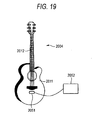
- the neck 2012 is provided with frets 2121 which divide the scales.
- frets 2121 which divide the scales.
- Multiple fret switches 2022 are arranged between the frets 2121.
- the fret switch 2022 detects the switch-on/off, and outputs a detection signal indicating the switch-on/off to the musical performance information acquiring section 2023.
- the guitar 2001 acquires a control signal, which instructs stoppage of the musical performance of the automatic musical performance device 2064, from the control signal DB (see Fig. 16 ).
- the guitar 2001 superimposes the control signal on the audio signal and outputs the resultant audio signal.
- the automatic musical performance device 2064 acquires the control signal to stop the musical performance of the automatic musical performance device 2064.
- the automatic musical performance device 2064 which is an external apparatus, stop the musical performance in accordance with the pose of the guitar 2001 (that is, the gestural musical performance of the performer using the guitar 2001).
- the guitar 2001 acquires a control signal, which instructs the mixer 2063 to turn up the volume of the guitar, from the control signal DB (see Fig. 16 ).
- the guitar 2001 superimposes the control signal on the audio signal and outputs the resultant control signal.
- the mixer 2063 acquires the control signal and turns up the volume of the guitar. As described above, it is possible to make the mixer 2063, which is an external apparatus, regulate the volume at the time of synthesis in accordance with the combination of the pose of the guitar 2001 (that is, the gestural musical performance of the performer using the guitar 2001) and the musical performance manipulation of the guitar 2001.
- an external apparatus can be controlled in accordance with the combination of the musical performance manipulation of the guitar 2001 (musical performance information) or the gestural musical performance of the performer using the guitar 2001 (pose information) and the reception period (the elapsed time or the number of beats after the musical performance has started). Therefore, the performer can easily control different external apparatuses with the same musical performance manipulation in accordance with the elapsed time.
- the guitar 2001 can control an external apparatus (for example, the effects unit 2061 or the guitar amplifier 2062) in accordance with the elapsed time, changing the effect or volume, thus it is appropriate to use when a musical piece is performed in which the tune changes with the elapsed time.
- the control device 2005 may include the fret switch 2022 (or a depress sensor) which detects the on/off of the fret 2121 for acquiring the musical performance information of the guitar 2004, and the string sensor 2021 which detects the vibration of each string 2010.
- the control device 2005 may also include the pose sensor 26 for acquiring the pose information of the guitar 2004.
- the control device of the invention may be configured to control an external apparatus in accordance with not only the musical performance manipulation but also the pose information by the pose sensor provided therein (the gestural musical performance of the performer).
- the musical performance information acquiring section 3012 acquires musical performance information in accordance with a musical performance manipulation of the performer.
- the acquired musical performance information is output to the musical sound generating section 3013 and the timing calculating section 3018.
- the musical performance information is, for example, information of depressed keys (note number), the key depressing timing (note-on and note-off), the key depressing speed (velocity), or the like.
- the control unit 3011 instructs which musical performance information is output (on the basis of which musical performance information musical sound is generated).
- the data superimposing section 3015 superimposes the musical performance information on the audio signal input from the reference clock superimposing section 3014.
- the timing calculating section 3018 calculates the time difference between the reference clock and the timing of superimposing the musical performance information in the data superimposing section 3015, and outputs information regarding the time difference to the data superimposing section 3015 together with the musical performance information.
- the information regarding the time difference is represented by the difference (offset value) from the reference clock.
- the timing calculating section 3018 converts the musical performance information and the offset value in a predetermined data format such that the musical performance information and the offset value can be superimposed on the audio signal, and outputs the musical performance information and the offset value to the data superimposing section 3015 (see (A) in Fig. 22 ).
- the control unit 3022 reads audio data recorded in the storage section 3023 and outputs audio data to the timing extracting section 3025.
- the timing extracting section 3025 decodes the offset value and the musical performance information superimposed on the audio signal, and input the offset value and the musical performance information to the control unit 3022.
- the control unit 3022 synchronously outputs the audio signal and the musical performance information to the outside on the basis of the reference clock input from the reference clock extracting section 3024 and the offset value.
- the tempo clock may also be output at this time.
- the sequence data output device includes a mode where a sequence data output device is embedded in an electronic musical instrument, such as an electronic piano, a mode where an audio signal is input from the existing musical instrument, a mode where an acoustic instrument or singing sound is collected by a microphone and an audio signal is input, and the like.
Abstract

Description
- The present invention relates to a musical performance-related information output device which outputs an audio signal and musical performance-related information related to a musical performance of a performer, a system including the musical performance-related information output device, and an electronic musical instrument.
- Various electronic musical instruments have been suggested which output audio data and musical performance information of musical instruments (for example, see Patent Literature 1).
- Musical performance information of musical instruments is stored as easily modifiable MIDI data separately from audio data. For this reason, an electronic musical instrument includes an audio terminal and a MIDI terminal, such that audio data is output from the audio terminal and musical performance information of a musical instrument is output from the MIDI terminal. Thus, two terminals (audio terminal and MIDI terminal) have to be provided.
- Since MIDI data includes tempo information, it is easy to regulate the reproduction time (tempo). In synchronizing audio data and MIDI data, audio data is recorded in synchronization with MIDI data. When existing audio data is used, it is necessary to manually regulate tempo information of MIDI data so as to match audio data. However, when the tempo is changed in the course of audio data, it takes a lot of labor to manually regulate the tempo information of MIDI data.
- Various electronic musical instruments have also been suggested which control an external apparatus (for example, see Patent Literature 1).
- For example, when a mixer is controlled by an electronic musical instrument, the electronic musical instrument stores a control signal for controlling the mixer as MIDI data, and outputs MIDI data to the mixer to control the mixer. For this reason, the electronic musical instrument has to include an audio output terminal for outputting an audio signal and a MIDI terminal for outputting MIDI data.
- Hence, in the data superimposing method described in
Patent Literature 1, digital audio data and musical performance information of a musical instrument are associated with each other and output, such that audio data and musical performance information of a musical instrument are output from a single terminal. - In recent years, a signal processing technique, such as time stretch, has been used so as to regulate the tempo of audio data (see Patent Literature 2).
- A technique has been suggested which embeds various kinds of data into an audio signal. For example,
Patent Literature 3 describes a technique which embeds data into an audio signal by using an electronic watermark for the purpose of copyright protection. -
Patent Literature 4 describes a technique which embeds a control signal into an audio signal in a time-series manner by using an electronic watermark. -
- Patent Literature 1:
JP-A-2003-316356 - Patent Literature 2:
JP-A-2003-280664 - Patent Literature 3:
JP-A-2006-251676 - Patent Literature 4:
JP-A-2006-323161 - However, according to the data superimposing method described in
Patent Literature 1, MIDI data is stored in the LSB (Least Significant Bit) of audio data. Accordingly, if audio data is converted to compressed audio, such as MP3, or audio data is emitted as an analog audio signal, associated information may be lost. Although an application program is provided which treats audio data and MIDI data, since there is no general-use data format, the application program is lacking in convenience. - Meanwhile, in the time stretch described in
Patent Literature 2, beats are extracted from audio data, and the tempo of the entire musical piece is changed with the absolute beat timing. In this case, however, the musical performance tempo of the performer is not reflected. That is, as shown by (A) inFig. 13 , during an actual musical performance, a performer does not conduct a musical performance in accordance with the absolute beat timing, but conducts a musical performance with varying the tempo faster or slower. For this reason, if the beats are extracted from audio data, time stretch is carried out, and as shown by (B) inFig. 13 , the tempo of the entire musical piece is changed with the absolute beat timing, the nuance (enthusiasm) of the musical performance is lost. - The method described in
Patent Literature 3 has no consideration of the timing at which information is embedded. For this reason, for example, when a silent part exists, there is a problem in that information cannot be superimposed, or information is superimposed with a significant shift from the timing at which information has to be actually embedded. - Meanwhile, in
Patent Literature 4, a time difference from the head of the audio signal is embedded, and in order to use the control signal at the time of reproduction, it is necessary to read the control signal from the head of the audio signal constantly. According to the method described inPatent Literature 4, a table (code list) has to be prepared in advance which indicates the relationship between the timing of the control signal and the timing of the musical performance, but it is impossible to use the method when the performer conducts a musical performance manipulation or the like randomly (in real time). In the method described inPatent Literature 2, the control signal is embedded in frames, but it is impossible to use the method when high resolution (for example, equal to or lower than several msec.) is necessary, for example, in a musical instrument musical performance. - Accordingly, an object of the invention is to provide a musical performance-related information output device and a system including the musical performance-related information output device capable of superimposing musical performance-related information (for example, musical performance information indicating a musical performance manipulation of a performer, tempo information indicating a musical performance tempo, a control signal for controlling an external apparatus, or the like) on an analog audio signal and outputting the resultant analog audio signal without damaging the general versatility of audio data.
- In order to achieve the object, a musical performance-related information output device according to an aspect of the invention comprises: a musical performance-related information acquiring section that is configured to acquire musical performance-related information related to a musical performance of a performer; a superimposing section that is configured to superimpose the musical performance-related information on an analog audio signal such that a modulated component of the musical performance-related information is included in a band higher than a frequency component of the analog audio signal generated in accordance with a musical performance manipulation of the performer; and an output section that outputs the analog audio signal on which the superimposing section superimposes the musical performance-related information.
- The above-described musical performance-related information output device may be configured in that the musical performance-related information acquiring section acquires musical performance information indicating the musical performance manipulation of the performer as the musical performance-related information.
- The above-described musical performance-related information output device may be configured in that the musical performance-related information acquiring section acquires tempo information indicating a musical performance tempo as the musical performance-related information.
- The above-described musical performance-related information output device may be configured in that the musical performance-related information acquiring section acquires a control signal for controlling an external apparatus as the musical performance-related information.
- The above-described musical performance-related information output device may be configured in that the musical performance-related information acquiring section acquires information regarding a reference clock, sequence data, a timing of superimposing the sequence data, and a time difference between the timing of superimposing the sequence data and the reference clock, as the musical performance-related information.
- According to the above-described musical performance-related information output device, musical performance-related information can be superimposed on an analog audio signal without damaging the general versatility of audio data.
-
-
Fig. 1 is an appearance diagram showing the appearance of a guitar in a first embodiment of the invention. -
Fig. 2 is a block diagram showing the function and configuration of the guitar in the first embodiment. -
Fig. 3 is a block diagram showing the function and configuration of a reproducing device in the first embodiment. -
Fig. 4 is an example of a screen displayed on a monitor in the first embodiment. -
Fig. 5 is an appearance diagram showing the appearance of a guitar with a musical performance information output device in a second embodiment of the invention. -
Fig. 6 is a block diagram showing the function and configuration of a musical performance information output device in the second embodiment. -
Fig. 7 is an appearance diagram showing the appearance of another guitar with a musical performance information output device in the second embodiment. -
Fig. 8 is a block diagram showing the configuration of a tempo information output device according to a third embodiment of the invention. -
Fig. 9 is a block diagram showing the configuration of a decoding device according to the third embodiment. -
Fig. 10 is a block diagram showing the configuration of a tempo information output device and a decoding device according to an application of the third embodiment. -
Fig. 11 is a block diagram showing the configuration of an electronic piano with an internal sequencer according to the third embodiment. -
Fig. 12 shows an example where the tempo information output device according to the third embodiment is attached to an acoustic guitar. -
Fig. 13 is a diagram illustrating time stretch. -
Fig. 14 is an appearance diagram showing the appearance of a guitar according to a fourth embodiment of the invention. -
Fig. 15 is a block diagram showing the function and configuration of the guitar according to the fourth embodiment. -
Fig. 16 shows an example of a control signal database according to the fourth embodiment. -
Fig. 17 is an explanatory view showing an example of a musical performance environment of the guitar according to the fourth embodiment. -
Fig. 18 shows another example of the control signal database according to the fourth embodiment. -
Fig. 19 is a top view of the appearance of a guitar with a control device according to a fifth embodiment of the invention when viewed from above. -
Fig. 20 is a block diagram showing the function and configuration of the control device according to the fifth embodiment. -
Fig. 21 shows the configuration of a sound processing system according to a sixth embodiment of the invention. -
Fig. 22 shows an example of data superimposed on an audio signal and the relationship between a reference clock and an offset value according to the sixth embodiment. -
Fig. 23 shows another example of data superimposed on an audio signal according to the sixth embodiment. -
Fig. 24 shows an example where a musical performance start timing is later than a musical performance information recording timing according to the sixth embodiment. -
Fig. 25 shows the configuration of a data superimposing section and a timing calculating section according to the sixth embodiment. - Embodiments of the invention will be described with reference to the drawings. Information related to a musical performance of a performer, such as musical performance information indicating a musical performance manipulation of a performer, tempo information indicating a musical performance tempo, a reference clock, a control signal (control information) for controlling an external apparatus, and the like, which will be described in the following embodiments may be collectively called musical performance-related information.
- A
guitar 1 according to a first embodiment of the invention will be described with reference toFigs. 1 and2 .Fig. 1 is an appearance diagram showing the appearance of the guitar. InFig. 1, (A) is a top view of the appearance of the guitar when viewed from above. InFig. 1, (B) is a partially enlarged view of a neck of the guitar. InFig. 2, (A) is a block diagram showing the function and configuration of the guitar. - First, the appearance of the
guitar 1 will be described with reference toFig. 1 . As shown by (A) inFig. 1 , theguitar 1 is an electronic stringed instrument (MIDI guitar), and includes abody 11 which is a body part and aneck 12 which is a neck part. - The
body 11 is provided with sixstrings 111 which are played in guitar playing style, and an output I/F 27 which outputs an audio signal. With regard to the sixstrings 111, a string sensor 22 (seeFig. 2 ) is arranged to detect the vibration of thestrings 111. - As shown by (B) in
Fig. 1 , theneck 12 is provided with frets 121 which divide the scales. Multiple fret switches 21 are arranged between the frets 121. - Next, the function and configuration of the
guitar 1 will be described with reference to (A) inFig. 2 . As shown by (A) inFig. 2 , theguitar 1 includes acontrol unit 20, a fretswitch 21, astring sensor 22, a musical performance information acquiring section (musical performance-related information acquiring section) 23, a musical performanceinformation converting section 24, a musicalsound generating section 25, a superimposingsection 26, and an output I/F 27. - The
control unit 20 controls the musical performanceinformation acquiring section 23 and the musicalsound generating section 25 on the basis of volume or tone set in theguitar 1. - The fret
switch 21 detects switch-on/off, and outputs a detection signal indicating switch-on/off to the musical performanceinformation acquiring section 23. - The
string sensor 22 includes a piezoelectric sensor or the like. Thestring sensor 22 converts the vibration of thecorresponding string 111 to a waveform to generate a waveform signal, and outputs the waveform signal to the musical performanceinformation acquiring section 23. - The musical performance
information acquiring section 23 acquires fingering information indicating the positions of the fingers of the performer on the basis of the detection signal (switch-on/off) input from thefret switch 21. Specifically, the musical performanceinformation acquiring section 23 acquires a note number associated with the fretswitch 21, which inputs the detection signal, and note-on (switch-on) and note-off (switch-off) of the note number. - The musical performance
information acquiring section 23 acquires stroke information indicating the intensity of a stroke on the basis of the waveform signal input from thestring sensor 22. Specifically, the musical performanceinformation acquiring section 23 acquires the velocity (intensity of sound) at the time of note-on. - The musical performance
information acquiring section 23 generates musical performance information (MIDI message) indicating the musical performance manipulation of the performer on the basis of the acquired fingering information and the stroke information, and outputs the musical performance information to the musical performanceinformation converting section 24 and the musicalsound generating section 25. At this time, even when note-on is input, if the stroke information is not input, the musical performanceinformation acquiring section 23 determines that musical performance is not conducted, and deletes the corresponding fingering information. Specifically, when the velocity at the time of note-on of the note number is 0, the musical performanceinformation acquiring section 23 deletes the note-on and note-off of the note number. - The musical performance
information converting section 24 generates MIDI data on the basis of the musical performance information input from the musical performanceinformation acquiring section 23, and outputs MIDI data to the superimposingsection 26. - The musical
sound generating section 25 includes a sound source. The musicalsound generating section 25 generates an audio signal on the basis of the musical performance information input from the musical performanceinformation acquiring section 23, and outputs the audio signal to the superimposingsection 26. - The superimposing
section 26 superimposes the musical performance information input from the musical performanceinformation converting section 24 on the audio signal input from the musicalsound generating section 25, and outputs the resultant audio signal to the output I/F 27. For example, the superimposingsection 26 phase-modulates a high-frequency carrier signal with the musical performance information (as a data code string of 0 and 1), such that the frequency component of the musical performance information is included in a band different from the frequency component (acoustic signal component) of the audio signal. Further, the following spread spectrum may be used. - In
Fig. 2 , is a block diagram showing an example of the configuration of the superimposingsection 26 when a spread spectrum is used. Although by (B) inFig. 2 , only digital signal processing has been described, the signals which are output to the outside may be analog signals (analog-converted signals). - In this example, a
multiplier 265 multiples an M-series pseudo noise code (PN code) output from the spreadcode generating section 264 and the musical performance information (data code string of 0 and 1) to spread the spectrum of the musical performance information. The spread musical performance information is input to anXOR circuit 266. TheXOR circuit 266 outputs an exclusive OR of the code input from themultiplier 265 and the output code before one sample input through adelay device 267 to differentially encode the spread musical performance information. It is assumed that the differentially-encoded signal is binarized with -1 and 1. The differential code binarized with -1 and 1 is output, such that the spread musical performance information can be extracted on the decoding side by multiplying the differential codes of two consecutive samples. - The differentially encoded musical performance information is band-limited to a baseband by an LPF (Nyquist filter) 268 and input to a
multiplier 270. Themultiplier 270 multiplies a carrier signal (a carrier signal in a band higher than the acoustic signal component) output from acarrier signal generator 269 and an output signal of theLPF 268, and frequency-shifts the differentially-encoded musical performance information to the pass-band. The differentially-encoded musical performance information may be up-sampled and then frequency-shifted. The frequency-shifted musical performance information is regulated in gain by again regulator 271, mixed with the audio signal by theadder 263, and output to the output I/F 27. - The audio signal output from the musical
sound generating section 25 is subjected to pass-band cutting in anLPF 261, is regulated in gain by again regulator 262, and is then input to theadder 263. However, theLPF 261 is not essential, and the acoustic signal component and the component of the modulated signal (the frequency component of the musical performance information to be superimposed) do not have to be completely band-divided. For example, if the carrier signal is about 20 to 25 kHz, even when the acoustic signal component and the component of the modulated signal slightly overlap each other, it is difficult for a listener to listen to the modulated signal, and the SN ratio can be secured such that the musical performance information can be decoded. The frequency band on which the musical performance information is superimposed is desirably an inaudible range equal to or higher than 20 kHz, but in the configuration in which the inaudible range is not used due to D/A conversion, encoding of compressed audio, or the like, for example, the musical performance information is superimposed on a high-frequency band equal to or higher than 15 kHz, reducing the effect for the sense of hearing. - The audio signal on which the musical performance information is superimposed in the above-described manner is output from the output I/
F 27 which is an audio output terminal. The audio signal is output to, for example, a storage device (not shown) and recorded as audio data. - Next, the usage of the recorded audio signal will be described. Although a musical piece based on the recorded audio signal can be reproduced by using a general reproducing device, here, a method will be described which reproduces the recorded audio signal by using a reproducing
device 3 capable of decoding the musical performance information superimposed on the audio signal. The function and configuration of the reproducingdevice 3 will be described with reference toFigs. 3 and4 . InFig. 3, (A) is a block diagram showing the function and configuration of the reproducing device.Fig. 4 shows an example of a screen which is displayed on a monitor. InFig. 4, (A) shows code information, and inFig. 4, (B) shows the fingering information of the performer. - As shown by (A) in
Fig. 3 , the reproducingdevice 3 includes a manipulatingsection 30, acontrol unit 31, an input I/F 32, adecoding section 33, adelay section 34, aspeaker 35, animage forming section 36, and amonitor 37. - The manipulating
section 30 receives a manipulation input of a user and outputs a manipulation signal according to the manipulation input to thecontrol unit 31. For example, the manipulatingsection 30 is a start button which instructs reproduction of the audio signal, a stop button which instructs stoppage of the audio signal, or the like. - The
control unit 31 controls thedecoding section 33 on the basis of the manipulation signal input from the manipulatingsection 30. - The audio signal on which the musical performance information is superimposed is input to the input I/
F 32. The input I/F 32 outputs the input audio signal to thedecoding section 33. - The
decoding section 33 extracts and decodes the musical performance information superimposed on the audio signal input from the input I/F 32 on the basis of an instruction of thecontrol unit 31 to acquire the musical performance information. Thedecoding section 33 outputs the audio signal to thedelay section 34, and outputs the acquired musical performance information to theimage forming section 36. The decoding method of thedecoding section 33 is different from the superimposing method of the musical performance information in the superimposingsection 26, but when the above-described spread spectrum is used, decoding is carried out as follows. - In
Fig. 3, (B) is a block diagram showing an example of the configuration of thedecoding section 33. The audio signal input from the input I/F is input to thedelay section 34 and anHPF 331. TheHPF 331 is a filter which removes the acoustic signal component. An output signal of theHPF 331 is input to adelay device 332 and amultiplier 333. A delay amount of thedelay device 332 is set to the time for one sample of the differential code. When the differential code is up-sampled, the delay amount is set to the time for one sample after up-sampling. Themultiplier 333 multiples the signal input from theHPF 331 and the signal before one sample output from thedelay device 332, and carries out delay detection processing. The differentially encoded signal is binarized with -1 and 1, and indicates the phase change from the code before one sample. Thus, with multiplication by the signal before one sample, the musical performance information before differential encoding (spread code) is extracted. - An output signal of the
multiplier 333 is extracted as a baseband signal through anLPF 334 which is a Nyquist filter, and is input to acorrelator 335. Thecorrelator 335 calculates the correlation with an input signal with the same spread code as the spread code output from the spreadcode generating section 264. A PN code having high self-correlativity is used for the spread code. Thus, with regard to a correlation value output from thecorrelator 335, the positive and negative peak components are extracted by apeak detecting section 336 in the cycle of the spread code (the cycle of the data code). Acode determining section 337 decodes the respective peak components as the data code (0, 1) of the musical performance information. In this way, the musical performance information superimposed on the audio signal is decoded. The differential encoding processing on the superimposing side and the delay detection processing on the decoding side are not essential. - The delay section (synchronous output means) 34 delays and outputs the audio signal by the time (hereinafter, referred to as delay time) for generation or superimposition of the musical performance information in the
guitar 1 or decoding in the reproducingdevice 3. Specifically, thedelay section 34 includes a buffer (not shown in figure) which stores the audio signal for the delay time (for example, 1 millisecond to several seconds). Thedelay section 34 temporarily stores the audio signal input from thedecoding section 33 in the buffer. If there is no free space in the buffer, thedelay section 34 acquires the initially stored audio signal from the audio signals stored in the buffer and outputs the acquired audio signal to thespeaker 35. Therefore, thedelay section 34 can output the audio signal to thespeaker 35 while delaying by the delay time. - The
speaker 35 emits sound on the basis of the audio signal input from thedelay section 34. - The
image forming section 36 generates image data representing the musical performance manipulation on the basis of the musical performance information input from thedecoding section 33, and outputs image data to themonitor 37. For example, as shown by (A) inFig. 4 , theimage forming section 36 generates image data which displays code information in the sequence of the musical performance by the performer in association with the musical performance timing (the elapsed time after the musical performance starts). Further, for example, as shown by (B) inFig. 4 , theimage forming section 36 generates image data which displays fingering information representing whichfingers 6 depress the frets 121 and thestrings 111. - The
monitor 37 displays image data input from theimage forming section 36. - As described above, the reproducing
device 3 delays and outputs the audio signal later than the musical performance information by the delay time, it is possible to output the audio signal and the musical performance information at the same time (that is, synchronously). Therefore, the reproducingdevice 3 can display the code information or fingering information based on the musical performance information on themonitor 37 at the same time with emission of sound according to the musical performance information. As a result, the audience can listen to emitted sound while confirming the code information or fingering information through themonitor 37. - Although in the first embodiment, the fingering information and the stroke information are output as the musical performance information, the invention is not limited thereto. For example, only the fingering information may be output as musical performance information, or information regarding a button manipulation for changing tune or volume may be output as musical performance information.
- Although in the first embodiment, even when note-on is input, if there is no stroke information (that is, when it is determined that the musical performance is not conducted), the musical performance
information acquiring section 23 deletes the corresponding fingering information, the fingering information may not be deleted. Thus, theguitar 1 can acquire, as musical performance information, the movements of the fingers when the performer does not play theguitar 1. For example, when there is time until the next musical performance manipulation, theguitar 1 can acquire, as musical performance information, the positions of the fingers of the performer while the performer is waiting. - Although in the first embodiment, the audio signal on which the musical performance information is superimposed is output through the output I/
F 27 and recorded, sound based on the audio signal on which the musical performance information is superimposed may be emitted and recorded by a microphone. - Although in the first embodiment, the
guitar 1 has been described as an example, the invention is not limited thereto, and may be applied to an electronic musical instrument, such as an electronic piano or an electronic violin (MIDI violin). For example, in the case of an electronic piano, note-on and note-off information of the keyboard of the electronic piano, effect, or manipulation information of a filter or the like may be generated as musical performance information. - Although in the first embodiment, the code information or the fingering information is displayed on the
monitor 37 on the basis of the musical performance information acquired by thedecoding section 33, a score may be generated on the basis of the musical performance information. Therefore, a composer can generate a score by playing only theguitar 1, thus, in generating a score, complicated work for transcribing scales may not be carried out. Further, the electronic musical instrument may be driven on the basis of the musical performance information. If the tone of another guitar is selected in the electronic musical instrument, the performer of theguitar 1 can conduct a musical performance in unison with another guitar (electronic musical instrument). - In the first embodiment, the reproducing
device 3 delays and outputs the audio signal later than the musical performance information by the delay time, it is possible to output the audio signal and the musical performance information at the same time. However, the reproducingdevice 3 may decode the musical performance information superimposed on the audio signal in advance, and may output the musical performance information in synchronization with the audio signal on the basis of the delay time, outputting the audio signal and the musical performance information at the same time. - A musical performance
information output device 5 according to a second embodiment will be described with reference toFigs. 5 and6 .Fig. 5 is an appearance diagram showing the appearance of a guitar with a musical performance information output device. InFig. 5, (A) is a top view of the appearance of the guitar when viewed from above. InFig. 5, (B) is a partial enlarged view of a neck of the guitar.Fig. 6 is a block diagram showing the function and configuration of the musical performance information output device. The second embodiment is different from the first embodiment in that an audio signal of a guitar 4 (acoustic guitar) which is an acoustic stringed instrument, instead of the audio signal of the guitar (MIDI guitar) 1 which is an electronic stringed instrument, is picked up by a microphone and recorded. The difference will be described. - As shown by (A) and (B) in
Fig. 5 , the musical performanceinformation output device 5 includesmultiple pressure sensors 51, a microphone 52 (corresponding to generating means), and amain body 53. Themicrophone 52 is provided in abody 11 of aguitar 4. Themultiple pressure sensors 51 are provided between frets 121 formed in theneck 12 of theguitar 4. - The
microphone 52 is, for example, a contact microphone for use in the pick-up or the like of a guitar or an electromagnetic microphone of an electric guitar. The contact microphone is a microphone which can be attached to the body of a musical instrument to cancel external noise and to detect not only the vibration of thestrings 111 of theguitar 4 but also the resonance of theguitar 4. If power is turned on, themicrophone 52 collects not only the vibration of thestrings 111 of theguitar 4 but also the resonance of theguitar 4 to generate an audio signal. Then, themicrophone 52 outputs the generated audio signal to an equalizer 531 (seeFig. 6 ). - A
pressure sensor 51 outputs the detection result indicating the on/off of the corresponding fret 121 to a musical performanceinformation acquiring section 532. - As shown in
Fig. 6 , themain body 53 is provided with anequalizer 531, a musical performanceinformation acquiring section 532, a musical performanceinformation converting section 24, a superimposingsection 26, and an output I/F 27. The musical performanceinformation converting section 24, the superimposingsection 26, and the output I/F27 have the same function and configuration as in the first embodiment, thus description thereof will be omitted. - The
equalizer 531 regulates the frequency characteristic of the audio signal input from themicrophone 52, and outputs the audio signal to the superimposingsection 26. - The musical performance
information acquiring section 532 generates fingering information indicating the on/off of the respective frets 121 on the basis of the detection result from thepressure sensor 51. The musical performanceinformation acquiring section 532 outputs the fingering information to the musical performanceinformation converting section 24 as musical performance information. - Thus, in the case of the
guitar 4 which does not generate an audio signal, the musical performanceinformation output device 5 can generate the audio signal in accordance with the vibration of thestrings 111 of theguitar 4 or the resonance of theguitar 4, superimpose the musical performance information on the audio signal, and output the resultant audio signal. - Although in the second embodiment, an example has been described where the
string sensors 22 which detect the vibration of therespective strings 111 are not provided, similarly to the first embodiment, thestring sensors 22 which detect the vibration of therespective strings 111 may be provided. In this case, the musical performanceinformation output device 5 can generate musical performance information including fingering information and stroke information. -
Fig. 7 is an appearance diagram showing the appearance of another guitar with a musical performance information output device. Although in the second embodiment, theacoustic guitar 4 has been described as an example, as shown inFig. 7 , even in an electric guitar, musical performance information can be output. Anelectric guitar 7 generates an audio signal itself, thus the audio signal is output from the output I/F 27 to the musical performanceinformation output device 5 without using themicrophone 52. A sensor which detects manipulation information of a tone arm for changing tune or a volume button for changing volume may be provided in theelectric guitar 7, and the musical performanceinformation output device 5 may output the manipulation information as musical performance information. - Although in the second embodiment, the
guitar 4 has been described as an example, the invention is not limited thereto, and may be applied to an acoustic instrument, such as a grand piano (keyboard instrument) or a trumpet (wind instrument). For example, in the case of a grand piano, amicrophone 52 is provided in the frame of the grand piano, and the musical performanceinformation output device 5 generates an audio signal through sound collection of themicrophone 52. Apressure sensor 51 which detects the on/off of each key and pressure applied to each key, or a switch which detects whether or not the pedal is stepped may be provided in the grand piano, and the musical performanceinformation output device 5 may generate musical performance information on the basis of the detection result of thepressure sensor 51 or the switch. - For example, in the case of a trumpet, a
microphone 52 is provided so as to cover the opening of the bell, and the musical performanceinformation output device 5 collects emitted sound by themicrophone 52 to generate an audio signal. Apressure sensor 51 for acquiring fingering information of the piston valves or a pneumatic sensor for acquiring how to blow the mouthpiece may be provided in the trumpet, and the musical performanceinformation output device 5 may generate musical performance information on the basis of the detection result of thepressure sensor 51 or the pneumatic sensor. - The musical performance information output device acquires musical performance information indicating the musical performance manipulation of the performer (for example, in the case of a guitar, fingering information indicating which strings and which fret are depressed, stroke information indicating the intensity of a stroke, manipulation information of various buttons for volume regulation, tune regulation, and the like). The musical performance information output device superimposes the musical performance information on the analog audio signal such that a modulated component of the musical performance information is included in a band different from the frequency component of the audio signal generated in accordance with the musical performance information, and outputs the resultant analog audio signal.
- For example, the musical performance information output device encodes M-series pseudo noise (PN code) through phase modulation with the musical performance information. The frequency band on which the musical performance information is superimposed is desirably an inaudible range equal to or higher than 20 kHz, but in the configuration in which an inaudible range is not used due to D/A conversion, encoding of compressed audio, or the like, for example, the musical performance information is superimposed on the high-frequency band equal to or higher than 15 kHz, reducing the effect for the sense of hearing. Then, the musical performance information output device emits sound based on the superimposed audio signal or outputs the superimposed audio signal from the audio terminal.
- Thus, the musical performance information output device can output both the musical performance information and the audio signal from the single terminal (or through sound emission). When the signal is recorded, the musical performance information can be superimposed on general-use audio data.
- The musical performance information output device includes generating means including a pickup, an acoustic microphone, or the like to generate an audio signal. Then, the musical performance superimposition output device may superimpose the musical performance information on the generated audio signal and may output the resultant audio signal.
- Thus, the musical performance information output device may not only be provided in the electronic musical instrument but also attached later to the existing musical instrument (for example, an acoustic guitar, a grand piano, an acoustic violin, or the like) for use.
- A musical performance system includes the above-described musical performance information output device and a reproducing device. The reproducing device decodes the audio signal output from the musical performance information output device to acquire the musical performance information. The reproducing device outputs the acquired musical performance information and the audio signal. At this time, the reproducing device delays and outputs the audio signal later than the musical performance information by the time required for superimposition and decoding of the musical performance information, to output the audio signal and the musical performance information at the same time. The reproducing device decodes the musical performance information superimposed on the audio signal in advance and synchronously outputs the audio signal and the musical performance information, to output the audio signal and the musical performance information at the same time.
- Thus, the code information or the fingering information based on the musical performance information is displayed on the monitor at the same time with emission of sound according to the musical performance information, thus the audience can listen to emitted sound while confirming the code information or the fingering information through the monitor.
- In
Fig. 8, (A) is a block diagram showing the configuration of a tempo information output device (musical performance-related information output device) according to a third embodiment of the invention. InFig. 8, (A) shows an example where an electronic musical instrument (electronic piano) also serves as a tempo information output device. Anelectronic piano 1001 shown by (A) inFig. 8 includes acontrol unit 1011, a musical performance information acquiring section (musical performance-related information acquiring section) 1012, a musicalsound generating section 1013, adata superimposing section 1014, an output interface (I/F) 1015, a tempoclock generating section 1016, a metronomesound generating section 1017, amixer section 1018, and a headphone I/F 1019. - The musical performance
information acquiring section 1012 acquires musical performance information in accordance with a musical performance manipulation of a performer. The musical performance information is, for example, information of depressed keys (note number), the key depressing timing (note-on and note-off), the key depressing speed (velocity), or the like. Thecontrol unit 1011 instructs which musical performance information is output (on the basis of which musical performance information musical sound is generated). - The musical
sound generating section 1013 includes an internal sound source, and receives the musical performance information from the musical performanceinformation acquiring section 1012 in accordance with the instruction of the control unit 1011 (setting of volume or the like) to generate musical sound (audio signal). - The tempo
clock generating section 1016 generates a tempo clock according to a set tempo. The tempo clock is, for example, a clock based on a MIDI clock (24 clocks per quarter notes), and is constantly output. The tempoclock generating section 1016 outputs the generated tempo clock to thedata superimposing section 1014 and the metronomesound generating section 1017. The metronomesound generating section 1017 generates metronome sound in accordance with the input tempo clock. Metronome sound is mixed with musical sound by a musical performance of the performer in themixer section 1018 and output to the headphone I/F 1019. The performer conducts the musical performance while listening to metronome sound (tempo) heard from the headphone. - A manipulator for tempo information input only (e.g., a tempo information input section indicated by a broken line in the drawing, such as a tap switch) may be provided in the
electronic piano 1001 to input the beat defined by the performer as a reference tempo signal and to extract tempo information. When an automatic accompaniment is conducted in a musical instrument mounted in an automatic musical performance system (sequencer), the tempoclock generating section 1016 also outputs the tempo clock to the automatic musical performance system (for example, seeFig. 11 ). - The
data superimposing section 1014 superimposes the tempo clock on the audio signal input from the musicalsound generating section 1013. As the superimposing method, a method is used in which a superimposed signal is scarcely heard. For example, a high-frequency carrier signal is phase-modulated with the tempo information (as a data code string indicating acode 1 with the clock timing), such that the frequency component of the tempo information is included in a band different from the frequency component (acoustic signal component) of the audio signal. - A method may be used in which pseudo noise, such as a PN code (M series), is superimposed at a weak level with no discomfort for the sense of hearing. At this time, a band on which pseudo noise is superimposed may be limited to an out-of-audibility (equal to or higher than 20 kHz) band. Pseudo noise, such as M series, has extremely high self-correlativity. Thus, the correlation between the audio signal and the same code as superimposed pseudo noise is calculated on the decoding side, such that the tempo clock can be extracted. The invention is not limited to M series, and another random number, such as Gold series, may be used.
- Each time the tempo clock is input from the tempo
clock generating section 1016, thedata superimposing section 1014 generates pseudo noise having a predetermined length, superimposes pseudo noise on the audio signal, and outputs the resultant audio signal to the output I/F 1015. - When pseudo noise is used, the following spread spectrum may be used. In
Fig. 8, (B) is a block diagram showing an example of the configuration of thedata superimposing section 1014 when a spread spectrum is used. - In this example, the M-series pseudo noise code (PN code) output from the spread
code generating section 1144 and the tempo information (data code string of 0 and 1) are multiplied by a multiplier 1265, spreading the spectrum of the tempo information. The spread tempo information is input to anXOR circuit 1146. TheXOR circuit 1146 outputs an exclusive OR of the code input from themultiplier 1145 and the output code before one sample input through adelay device 1147 to differentially encodes the spread tempo information. It is assumed that the differentially-encoded signal is binarized with -1 and 1. The differential code binarized with -1 and 1 is output, such that the spread tempo information can be extracted on the decoding side by multiplying the differential codes of two consecutive samples. - The differentially encoded tempo information is band-limited to the baseband in an LPF (Nyquist filter) 1148 and input to a
multiplier 1150. Themultiplier 1150 multiplies a carrier signal (a carrier signal in a band higher than the acoustic signal component) output from acarrier signal generator 1149 and an output signal of theLPF 1148, and frequency-shifts the differentially-encoded tempo information to the pass-band. The differentially-encoded tempo information may be up-sampled and then frequency-shifted. The frequency-shifted tempo information is regulated in gain by again regulator 1151, mixed with the audio signal by anadder 1143, and output to the output I/F 1027. - The audio signal output from the musical
sound generating section 1013 is subjected to pass-band cutting in anLPF 1141, is regulated in gain by again regulator 1142, and is then input to theadder 1143. However, theLPF 1141 is not essential, and the acoustic signal component and the component of the modulated signal (the frequency component of the superimposed tempo information) do not have to be completely band-divided. For example, if the carrier signal is about 20 to 25 kHz, even when the acoustic signal component and the component of the modulated signal slightly overlap each other, it is difficult for the listener to listen to the modulated signal, and the SN ratio can be secured such that the tempo information can be decoded. The frequency band on which the tempo information is superimposed is desirably an inaudible range equal to or higher than 20 kHz, but in the configuration in which the inaudible range is not used due to D/A conversion, encoding of compressed audio, or the like, for example, the tempo information is superimposed on a high-frequency band equal to or higher than 15 kHz, reducing the effect for the sense of hearing. - The audio signal on which the tempo information is superimposed in the above-described manner is output from the output I/
F 1015 which is an audio output terminal. - The audio signal output from the output I/
F 1015 is input to adecoding device 1002 shown by (A) inFig. 9 . Thedecoding device 1002 has a function as a recorder for recording an audio signal, a function as a reproducer for reproducing an audio signal, and a function as a decoder for decoding tempo information superimposed on an audio signal. The audio signal output from theelectronic piano 1001 can be treated similarly to the usual audio signal, and can be thus recorded by another general recorder. Recorded audio data is general-use audio data, and can be thus reproduced by a general audio reproducer. - Here, with regard to the
decoding device 1002, the function for decoding tempo information superimposed on an audio signal and the use example of the decoded tempo information will be mainly described. - In (A) of
Fig. 9 , thedecoding device 1002 includes an input I/F 1021, acontrol unit 1022, astorage section 1023, and a tempoclock extracting section 1024. Thecontrol unit 1022 records an audio signal input from the input I/F 1021, and records the audio signal in thestorage section 1023 as general-use audio data. Thecontrol unit 1022 reads audio data recorded in thestorage section 1023 and outputs audio data to the tempoclock extracting section 1024. - The tempo
clock extracting section 1024 generates pseudo noise identical to pseudo noise generated by thedata superimposing section 1014 of theelectronic piano 1001 and calculates the correlation with the reproduced audio signal. Pseudo noise superimposed on the audio signal is a signal having extremely high self-correlativity. Thus, when the correlation between the audio signal and the pseudo noise is calculated, as shown by (B) inFig. 9 , a steep peak is extracted regularly. The peak-generated timing of the correlation represents a musical performance tempo (tempo clock). - When the spread spectrum described with reference to (B) in
Fig. 8 is used, the tempoclock extracting section 1024 decodes the tempo information and extracts the tempo clock as follows. InFig. 9, (C) is a block diagram showing an example of the configuration of the tempoclock extracting section 1024. The input audio signal is input to anHPF 1241. TheHPF 1241 is a filter which removes the acoustic signal component. An output signal of theHPF 1241 is input to adelay device 1242 and amultiplier 1243. The delay amount of thedelay device 1242 is set to the time for one sample of the above-described differential code. When the differential code is up-sampled, the delay amount is set to the time for one sample after up-sampling. Themultiplier 1243 multiplies a signal input from theHPF 1241 and a signal before one sample output from thedelay device 1242, and carries out delay detection processing. The differentially encoded signal is binarized with -1 and 1, and indicates the phase change from the code before one sample. Thus, with multiplication by the signal before one sample, the tempo information before differential encoding (the spread code) is extracted. - An output signal of the
multiplier 1243 is extracted as a baseband signal through anLPF 1244 which is a Nyquist filter, and is input to acorrelator 1245. Thecorrelator 1245 calculates the correlation with an input signal with the same pseudo noise code as the pseudo noise code output from the spreadcode generating section 1244. With regard to a correlation value output from thecorrelator 1245, the positive and negative peak components are extracted by apeak detecting section 1246 in the cycle of pseudo noise (the cycle of the data code). Acode determining section 1247 decodes the respective peak components as the data code (0,1) of the tempo information. In this way, the tempo information superimposed on the audio signal is decoded. The differential encoding processing on the superimposing side and the delay detection processing on the decoding side are not essential. - The tempo clock extracted in the above-described manner can be used for an automatic musical performance by a sequencer insofar as the tempo clock is based on the MIDI clock. For example, an automatic musical performance in which the sequencer reflects its own musical performance tempo can be realized.
- As shown in
Fig. 11 , in anelectronic piano 1005 with aninternal sequencer 1101, if thesequencer 1101 is configured to carry out an automatic musical performance on the basis of tempo information, musical sound by a musical performance of the performer and musical sound of the automatic musical performance can be synchronized with each other. Therefore, the performer can conduct only a musical performance manipulation to generate an audio signal in which musical sound by his/her musical performance and musical sound by an automatic musical performance are synchronized with each other. Further, like a karaoke machine, the audio signal can be synchronized with a video signal. - The extracted tempo clock may be used as a reference clock at the time of time stretch of audio data, significantly reducing complexity at the time of editing. As shown by (C) in
Fig. 13 , a correction time is calculated from the difference between the tempo information and the musical performance information included in base audio data subjected to time stretch, and the correction time is added to time-stretched audio data according to a new tempo, such that the tempo can be changed without losing the nuance (enthusiasm) of the musical performance. For example, where the difference between each beat of the tempo information and the timing of note-on is α, the base tempo is T1, and time-stretched the tempo is T2, the correction time becomes α×(T2/T1). Therefore, even when time stretch is carried out, there is no case where the nuance of the musical performance is changed. - In the case of the superimposing method using pseudo noise, such as M series, various applications described below may be made.
Fig. 10 is a block diagram showing the configuration of a tempo information output device and a decoding device according to an application example. The same parts as those inFigs. 8 and9 are represented by the same reference numerals, and description thereof will be omitted. - An
electronic piano 1003 according to the application example includes a downbeat tempoclock generating section 1161 and an upbeat tempoclock generating section 1162, instead of the tempoclock generating section 1016. Thedecoding device 1004 includes a downbeat tempoclock extracting section 1241 and an upbeat tempoclock extracting section 1242, instead of the tempoclock extracting section 1024. - The downbeat tempo
clock generating section 1161 generates a tempo clock for each downbeat timing (bar). The upbeat tempoclock generating section 1162 generates a tempo clock for each upbeat (beat) timing. - Each time the tempo clock is input from the downbeat tempo
clock generating section 1161 and each time the tempo clock is input from the upbeat tempoclock generating section 1162, thedata superimposing section 1014 generates pseudo noise and superimposes the pseudo noise on the audio signal. Thedata superimposing section 1014 generates the pseudo noise with different patterns (pseudo noise for downbeat and pseudo noise for upbeat) with the timing at which the tempo clock is input from the downbeat tempoclock generating section 1161 and with the timing at which the tempo clock is input from the upbeat tempoclock generating section 1162. - The downbeat tempo
clock extracting section 1241 and the upbeat tempoclock extracting section 1242 of thedecoding device 1004 respectively generate pseudo noise identical to pseudo noise for downbeat and pseudo noise for upbeat generated by thedata superimposing section 1014, and calculates the correlation with the reproduced audio signal. - Pseudo noise for downbeat and pseudo noise for upbeat are superimposed on the audio signal for each bar timing and for each beat timing, respectively. These are signals having extremely high self-correlativity. Thus, if the correlation between the audio signal and pseudo noise is calculated, as shown by (C) in
Fig. 10 , a steep peak is extracted regularly. The peak-generated timing extracted by the downbeat tempo clock extracting section 241 represents the bar timing (downbeat tempo clock), and the peak-generated timing extracted by the upbeat tempoclock extracting section 1242 represents the beat timing (upbeat tempo clock). The signals of pseudo noise use different patterns, thus there is no case where the signals of pseudo noise interfere with each other, such that the correlation can be calculated with high accuracy. - In the case of four beats, the bar timing has a cycle four times greater than the beat timing, thus the noise length of the pseudo noise can be set four times greater. Therefore, the SN ratio can be secured by as much, and the level of pseudo noise can be reduced.
- If more patterns of pseudo noise are used, different kinds of pseudo noise may be superimposed with each beat timing, and it is possible to cope with a variety of tempos, including a compound beat and the like. In particular, when Gold series is used as pseudo noise, various code series can be generated. Thus, even when a compound beat is used or even when the number of beats is large, different code series can be used for each beat. Even when the spread spectrum described with reference to
(B) in Fig. 8 and(C) in Fig. 9 is used, the spread processing can be carried out for the tempo information using different kinds of pseudo noise with reach beat timing or bar timing. - The tempo information output device of this embodiment is not limited to a mode where a tempo information output device is embedded in an electronic musical instrument, and may be attached to the existing musical instrument later.
Fig. 12 shows an example where a tempo information output device is attached to a guitar. InFig. 12 , an electric acoustic guitar will be described which outputs an analog audio signal. The same parts as those inFig. 8 are represented by the same reference numerals, and description thereof will be omitted. - As shown by
(A) in Fig. 12 and (B) in Fig. 12 , a tempoinformation output device 1009 includes an audio input I/F 1051 and a fretswitch 1052. A line output terminal of aguitar 1007 is connected to the audio input I/F 1051. - The audio input I/
F 1051 receives musical performance sound (audio signal) from theguitar 1007, and outputs musical performance sound to thedata superimposing section 1014. The fretswitch 1052 is a manipulator for tempo information input only, and inputs the beat defined by the performer as a reference tempo signal. The tempoclock generating section 1016 receives the reference tempo signal from thefret switch 1052 and extracts tempo information. - As described above, the existing musical instrument having the audio output terminal can use the tempo information output device of the invention, and can superimpose the tempo information, in which the musical performance tempo of the performer is reflected, on the audio signal.
- The tempo information output device of this embodiment is not limited to an example where a tempo information output device is attached to an electronic piano or an electric acoustic guitar. If musical sound is collected by the usual microphone, even an acoustic instrument having no line output terminal can use the tempo information output device of the invention. The invention is not limited to a musical instrument, and singing sound falls within the technical scope of an audio signal which is generated in accordance with the musical performance manipulation in the invention. Singing sound may be collected by a microphone, and tempo information may be superimposed on singing sound.
- The tempo information output device (musical performance-related information output device) includes output means for outputting the audio signal generated in accordance with the musical performance manipulation of the performer. The tempo information indicating the musical performance tempo of the performer is superimposed on the audio signal. The tempo information output device superimposes the tempo information such that a modulated component of the tempo information is included in a band different from the frequency component of the audio signal. The tempo information is superimposed as beat information (tempo clock), such as a MIDI clock. The beat information is constantly output by the automatic musical performance system (sequencer).
- For this reason, the tempo information output device can output the audio signal with the tempo information, in which the musical performance tempo of the performer is reflected (by the single line). The output audio signal can be treated in the same manner as the usual audio signal, thus the audio signal can be recorded by a recorder or the like and can be used as general-use audio data. The time difference from the actual musical performance timing can be calculated from the tempo information, and even when the reproduction time is regulated through time stretch or the like, there is no case where the nuance of the musical performance is changed. The tempo information output device includes a mode where a tempo information output device is embedded in an electronic musical instrument, such as an electronic piano, a mode where an audio signal is input from the existing musical instrument, a mode where acoustic instrument or singing sound is collected and an audio signal is input, and the like.
- A reference tempo signal which is the reference of the musical performance tempo may be input from the outside, such as a metronome, and tempo information may be extracted on the basis of the reference tempo signal. The beat defined by the performer may be input as the reference tempo signal by the fret switch or the like. In this case, as in an acoustic instrument or the like, even when tempo information cannot be generated, the tempo information can be extracted.
- A mode may also be made such that a sound processing system includes a decoding device which decodes the tempo information by using the above-described tempo information output device. The superimposing means of the tempo information output device superimpose pseudo noise on the audio signal with the timing based on the musical performance tempo to superimpose the tempo information. As pseudo noise, for example, a signal having high self-correlativity, such as a PN code, is used. The tempo information output device generates a signal having high self-correlativity with the timing based on the musical performance tempo (for example, for each beat), and superimposes the generated signal on the audio signal. Therefore, even when sound emission is made as an analog audio signal, there is no case where the superimposed tempo information is lost.
- The decoding device includes input means to which the audio signal is input, and decoding means for decoding the tempo information. The decoding means calculates the correlation between the audio signal input to the input means and pseudo noise, and decodes the tempo information on the basis of the peak-generated timing of the correlation. Pseudo noise superimposed on the audio signal has extremely high self-correlativity. Thus, the decoding device calculates the correlation between the audio signal and pseudo noise, and the peak of the correlation is extracted for each beat timing. Therefore, the peak-generated timing of the correlation represents the musical performance tempo.
- Even when pseudo noise having high self-correlativity, such as a PN code, is at low level, the peak of the correlation can be extracted. Thus, with respect to sound which has no discomfort for the sense of hearing (sound which is scarcely heard), the tempo information can be superimposed and decoded with high accuracy. Further, if pseudo noise is superimposed only in a high band equal to or higher than 20 kHz, pseudo noise can be further scarcely heard.
- The invention may be configured such that the tempo information extracting means extracts multiple kinds of tempo information (for example, beat timing and bar timing) in accordance with each timing of the musical performance tempo, and the superimposing means superimposes multiple kinds of pseudo noise to superimpose the multiple kinds of tempo information. In this case, the decoding means of the decoding device calculates the correlation between the audio signal input to the input means and the multiple kinds of pseudo noise, and decodes the multiple kinds of tempo information on the basis of the peak-generated timing of the respective correlations. That is, if different patterns of pseudo noise are superimposed with the beat timing and the bar timing, there is no interference between pseudo noise, and the beat timing and the bar timing can be individually superimposed and decoded with high accuracy.
When tempo information is superimposed using pseudo noise, the tempo information output device may encode the M-series pseudo noise (PN code) through phase modulation with the tempo information. The frequency band on which the tempo information is superimposed is desirably an inaudible range equal to or higher than 20 kHz, but in the configuration in which an inaudible range is not used due to D/A conversion, encoding of compressed audio, or the like, for example, the tempo information is superimposed on the high-frequency band equal to or higher than 15 kHz, reducing the effect for the sense of hearing. - A
MIDI guitar 2001 which is an electronic stringed instrument according to a fourth embodiment of the invention will be described with reference toFigs. 14 and15 .Fig. 14 is an appearance diagram showing the appearance of a guitar. InFig. 14, (A) is a top view of the appearance of a guitar when viewed from above. InFig. 14, (B) is a partial enlarged view of a neck of a guitar. InFig. 15, (A) is a block diagram showing the function and configuration of a guitar.Fig. 16 shows an example of a control signal database. - First, the appearance of a MIDI guitar (hereinafter, simply referred to as a guitar) 2001 will be described with reference to
Fig. 14 . As shown by (A) inFig. 14 , theguitar 2001 includes abody 2011 and aneck 2012. - The
body 2011 is provided with sixstrings 2010 which are plucked in accordance with the playing styles of the guitar, and an output I/F 2030 which outputs an audio signal. The sixstrings 2010 are provided with string sensors 2021 (see (A) inFig. 15 which detect the vibration of thestrings 2010. - As shown by (B) in
Fig. 14 , theneck 2012 is provided with frets 2121 which divide the scales. Multiple fretswitches 2022 are arranged between the frets 2121. - Next, the function and configuration of the
guitar 2001 will be described with reference to (A) inFig. 15 . As shown by (A) inFig. 15 , theguitar 2001 includes acontrol unit 2020, astring sensor 2021, a fretswitch 2022, a musical performanceinformation acquiring section 2023, a musicalsound generating section 2024, aninput section 2025, apose sensor 2026, astorage section 2027, a control signal generating section (control signal generating means and musical performance-related information acquiring means) 2028, asuperimposing section 2029, and an output I/F 2030. - The
control unit 2020 controls the musical performanceinformation acquiring section 2023 and the musicalsound generating section 2024 on the basis of volume or tone set in theguitar 2001. - The
string sensor 2021 includes a piezoelectric sensor or the like. Thestring sensor 2021 generates a waveform signal which is obtained by converting the vibration of thecorresponding string 2010 to a waveform, and outputs the waveform signal to the musical performanceinformation acquiring section 2023. - The fret
switch 2022 detects the switch-on/off, and outputs a detection signal indicating the switch-on/off to the musical performanceinformation acquiring section 2023. - The musical performance
information acquiring section 2023 acquires fingering information indicating the positions of the fingers of the performer on the basis of the detection signal from thefret switch 2022. Specifically, the musical performanceinformation acquiring section 2023 acquires a note number associated with the fretswitch 2022, which inputs the detection signal, and note-on (switch-on) and note-off (switch-off) of the note number. - The musical performance
information acquiring section 2023 acquires stroke information indicating the intensity of a stroke on the basis of the waveform signal from thestring sensor 2021. Specifically, the musical performanceinformation acquiring section 2023 acquires the velocity (intensity of sound) at the time of note-on. - The musical performance
information acquiring section 2023 generates musical performance information (MIDI message) indicating the musical performance manipulation of the performer on the basis of the acquired fingering information and stroke information, and outputs the musical performance information to the musicalsound generating section 2024 and the controlsignal generating section 2028. The musical performance information output to the controlsignal generating section 2028 is not limited to the MIDI message, and data in any format may be used. - The musical
sound generating section 2024 includes a sound source, generates an audio signal in an analog format on the basis of the musical performance information input from the musical performanceinformation acquiring section 2023, and outputs the audio signal to thesuperimposing section 2029. - The
input section 2025 receives the input of a manipulation for controlling an external apparatus, and outputs manipulation information according to the manipulation to the controlsignal generating section 2028. Then, the controlsignal generating section 2028 generates a control signal according to the manipulation information from theinput section 2025, and outputs the control signal to thesuperimposing section 2029. - The
pose sensor 2026 outputs pose information generated through detection of the pose of theguitar 2001 to the controlsignal generating section 2028. For example, thepose sensor 2026 generates pose information (upper) if theneck 2012 turns upward with respect to thebody 2011, generates pose information (left) if theneck 2012 turns left with respect to thebody 2011, and generates pose information (upward left) if theneck 2012 turns upward left with respect to thebody 2011. - The
storage section 2027 stores a control signal database (hereinafter, referred to as a control signal DB) shown inFig. 16 . The control signal DB is referenced by the controlsignal generating section 2028. The control signal DB is configured such that specific musical performance information (for example, on/off of a specific fret switch 2022) for controlling the external apparatus or specific pose information of theguitar 2001 is made as a database. The control signal DB stores the specific musical performance information or pose information in association with a control signal for controlling the external apparatus. - The control
signal generating section 2028 acquires a control signal for controlling the external apparatus from thestorage section 2027 on the basis of the musical performance information from the musical performanceinformation acquiring section 2023 and the pose information from thepose sensor 2026, and outputs the control signal to thesuperimposing section 2029. - The
superimposing section 2029 superimposes the control signal input from the controlsignal generating section 2028 on the audio signal input from the musicalsound generating section 2024, and outputs the resultant audio signal to the output I/F 2030. For example, thesuperimposing section 2029 phase-modulates a high-frequency carrier signal with the control signal (data code string of 0 and 1), such that the frequency component of the control signal is included in a band different from the frequency component (acoustic signal component) of the audio signal. A spread spectrum as described below may be used. - In
Fig. 15, (B) is a block diagram showing an example of the configuration of thesuperimposing section 2029 when a spread spectrum is used. Although in (B) ofFig. 15 , only digital signal processing has been described, the signals which are output to the outside may be analog signals (analog-converted signals). - In this example, the M-series pseudo noise code (PN code) output from the spread
code generating section 2294 and the control signal (as a data code string of 0 and 1) are multiplied by amultiplier 2295 to spread the spectrum of the control signal. The spread control signal is input to anXOR circuit 2296. TheXOR circuit 2296 outputs an exclusive OR of the code input from themultiplier 2295 and the output code before one sample input through adelay device 2297 to differentially encode the spread control signal. The differentially-encoded signal is binarized with -1 and 1. The differential code binarized with -1 and 1 is output, such that the spread musical performance information can be extracted on the decoding side by multiplying the differential codes of two consecutive samples. - The differentially encoded control signal is band-limited to the baseband in an LPF (Nyquist filter) 2298 and input to a
multiplier 2300. Themultiplier 2300 multiplies a carrier signal (a carrier signal in a band higher than the acoustic signal component) output from acarrier signal generator 2299 and an output signal of theLPF 2298, and frequency-shifts the control differentially-encoded signal to the pass-band. The control differentially-encoded signal may be up-sampled and then frequency-shifted. The frequency-shifted control signal is regulated in gain by again regulator 2301, is mixed with the audio signal by anadder 2293, and is output to the output I/F 2030. - The audio signal output from the musical
sound generating section 2024 is subjected to pass-band cutting in anLPF 2291, is regulated in gain by thegain regulator 2292, and is then input to theadder 2293. However, theLPF 2291 is not essential, the acoustic signal component and the component of the modulated signal (the frequency component of the superimposed control signal) do not have to be completely band-divided.
For example, if the carrier signal is about 20 to 25 kHz, even when the acoustic signal component and the component of the modulated signal slightly overlap each other, it is difficult for the listener to listen to the modulated signal, and the SN ratio can be secured such that the control signal can be decoded. The frequency band on which the control signal is superimposed is desirably an inaudible range equal to or higher than 20 kHz, but in the configuration in which the inaudible range is not used due to D/A conversion, encoding of compressed audio, or the like, for example, the control signal is superimposed on a high-frequency band equal to or higher than 15 kHz, reducing the effect for the sense of hearing. - The audio signal on which the control signal is superimposed in the above-described manner is output from the output I/
F 2030 which is an audio output terminal. The output I/F 2030 outputs the audio signal input from thesuperimposing section 2029 to an effects unit 2061 (seeFig. 17 ). - Next, the control of the external apparatus by the musical performance or the like of the
guitar 1 will be described with reference toFig. 17. Fig. 17 is an explanatory view showing an example of a musical performance environment of a guitar. As shown by (A) inFig. 17 , theguitar 2001 is sequentially connected to aneffects unit 2061 which regulates a sound effect, aguitar amplifier 2062 which amplifies the volume of musical performance sound of theguitar 2001, amixer 2063 which mixes input sound (musical performance sound of theguitar 2001, sound collected by a microphone MIC, and sound reproduced by an automatic musical performance device 2064), and a speaker SP. The microphone MIC which collects sound of a vocalist, and the automaticmusical performance device 2064 which carries out an automatic musical performance of MIDI data provided therein are connected to themixer 2063. - At least one of the external apparatuses shown by (A) in
Fig. 17 including theeffects unit 2061, theguitar amplifier 2062, themixer 2063, and the automaticmusical performance device 2064 includes a decoding section, and decodes the control signal superimposed on the audio signal. The decoding method varies depending on the superimposing method of the control signal in thesuperimposing section 2029. When the above-described spread spectrum is used, decoding is carried out as follows. - In
Fig. 17, (B) is a block diagram showing an example of the configuration of the decoding section. The audio signal input to the decoding section is input to anHPF 2091. TheHPF 2091 is a filter for removing the acoustic signal component. An output signal of theHPF 2091 is input to adelay device 2092 and amultiplier 2093. The delay amount of thedelay device 2092 is set to the time for one sample of the differential code. When the differential code is up-sampled, the delay amount is set to the time for one sample after up-sampling. Themultiplier 2093 multiplies the signal input from theHPF 2091 and the signal before one sample output from thedelay device 2092, and carries out delay detection processing. The differentially encoded signal is binarized with -1 and 1, and indicates the phase change from the code before one sample. Thus, with multiplication by the signal before one sample, the musical performance information before differential encoding (the spread code) is extracted. - An output signal of the
multiplier 2093 is extracted as a baseband signal through anLPF 2094 which is a Nyquist filter, and input to acorrelator 2095. Thecorrelator 2095 calculates the correlation with an input signal with the same spread code as the spread code output from the spreadcode generating section 2294. A PN code having high self-correlativity is used for the spread code. Thus, with regard to a correlation value output from thecorrelator 2095, the positive and negative peak components are extracted by apeak detecting section 2096 in the cycle of the spread code (the cycle of the data code). Acode determining section 2097 decodes the respective peak components as the data code (0,1) of the control signal. In this way, the control signal superimposed on the audio signal is decoded. The decoded control signal is used to control the respective external apparatuses. The differential encoding processing on the superimposing side and the delay detection processing on the decoding side are not essential. - For example, in (A) of
Fig. 17 , if thestring sensor 2021 does not detect the vibration of thestring 2010, and the fretswitch 2022 detects that the first to sixth strings of the first fret are depressed, theguitar 2001 acquires a control signal, which instructs the start of the musical performance of the automaticmusical performance device 2064, from the control signal DB (seeFig. 16 ). Theguitar 2001 superimposes the control signal on the audio signal and outputs the resultant audio signal. The automaticmusical performance device 2064 acquires the control signal to start the musical performance of the automaticmusical performance device 2064. As described above, it is possible to make the automaticmusical performance device 2064, which is an external apparatus, start the musical performance in accordance with the musical performance manipulation of the guitar 2001 (a musical performance manipulation which does not generate an audio signal). In this case, the decoding section may be embedded in the automaticmusical performance device 2064, and the audio signal on which the control signal is superimposed may be input to the automaticmusical performance device 2064, such that the automaticmusical performance device 2064 may decode the control signal. Alternatively, the decoding section may be embedded in themixer 2063, themixer 2063 may decode the control signal, and the decoded control signal may be input the automaticmusical performance device 2064. - If the
pose sensor 2026 detects that theneck 2012 turns downward with respect to thebody 2011 immediately after theneck 2012 turns upward with respect to thebody 2011, theguitar 2001 acquires a control signal, which instructs stoppage of the musical performance of the automaticmusical performance device 2064, from the control signal DB (seeFig. 16 ). Theguitar 2001 superimposes the control signal on the audio signal and outputs the resultant audio signal. The automaticmusical performance device 2064 acquires the control signal to stop the musical performance of the automaticmusical performance device 2064. As described above, it is possible to make the automaticmusical performance device 2064, which is an external apparatus, stop the musical performance in accordance with the pose of the guitar 2001 (that is, the gestural musical performance of the performer using the guitar 2001). - If the
pose sensor 2026 detects that theneck 2012 turns upward with respect to thebody 2011 and thestring sensor 2021 detects the vibration of thestring 2010, theguitar 2001 acquires a control signal, which instructs themixer 2063 to turn up the volume of the guitar, from the control signal DB (seeFig. 16 ). Theguitar 2001 superimposes the control signal on the audio signal and outputs the resultant control signal. Themixer 2063 acquires the control signal and turns up the volume of the guitar. As described above, it is possible to make themixer 2063, which is an external apparatus, regulate the volume at the time of synthesis in accordance with the combination of the pose of the guitar 2001 (that is, the gestural musical performance of the performer using the guitar 2001) and the musical performance manipulation of theguitar 2001. - If the fret
switch 2022 detects that a specific fret (the second string and the fifth fret, and the third string and the sixth fret) is depressed, and thestring sensor 2021 detects the vibration of thestring 2010, theguitar 2001 acquires a control signal, which instructs theeffects unit 2061 to change an effect, from the control signal DB (seeFig. 16 ). Theguitar 2001 superimposes the control signal on the audio signal and outputs the resultant audio signal. Theeffects unit 2061 acquires the control signal and changes the effect. As described above, it is possible to make theeffects unit 2061, which is an external apparatus, change the effect in accordance with the musical performance manipulation of the guitar 2001 (a musical performance manipulation which generates an audio signal). - The above-described contents are an example, and the
guitar 2001 registers a control signal for controlling an external apparatus in the control signal DB, and can control an acoustic-related device, such as theeffects unit 2061 or theguitar amplifier 2062, or a stage-related device, such as an illumination or a camera, as an external apparatus. Thus, the external apparatus (the automaticmusical performance device 2064, themixer 2063, or the like) can be controlled in accordance with the gestural musical performance of the performer using theguitar 2001 or the musical performance manipulation of theguitar 2001. - The association of the control signal stored in the control signal DB and the musical performance information or the pose information may be edited. In this case, the
guitar 2001 is provided with a control signal input section (not shown in figure), such that the performer registers a control signal for controlling an external apparatus in the control signal DB. The performer conducts a musical performance or a gestural musical performance, and the musical performanceinformation acquiring section 2023 acquires the musical performance information or the pose information and registers the musical performance information or the pose information in the control signal DB in association with the registered control signal. Thus, the performer can easily register a control signal in accordance with his/her purpose. - Instead of the control signal DB, a control signal DB may be provided in which specific musical performance information or pose information and the reception period in which the input of the specific musical performance information or pose information is received are stored in association with the control signal.
Fig. 18 shows another example of the control signal database. In this case, theguitar 2001 includes a measuring section (not shown) which measures the elapsed time (or the number of beats) after the musical performance has started. For example, if, in one to two minutes after the musical performance has started, thepose sensor 2026 detects that theneck 2012 turns upward with respect to thebody 2011, and thestring sensor 2021 detects the vibration of thestring 2010, theguitar 2001 acquires a control signal, which instructs themixer 2063 to turn up the volume of the guitar, from the control signal DB shown inFig. 18 . In a period out of one to two minutes after the musical performance has started, even when the gesture is detected, theguitar 2001 does not acquire a control signal, thus themixer 2063 is not manipulated. - For example, if, in the eighth to the tenth beat or the fourteenth beat to the twentieth beat after the musical performance has started, the fret
switch 2022 detects that the second string of the fifth fret and the third string of the sixth fret are depressed, and thestring sensor 2021 detects the vibration of thestring 2010, theguitar 2001 acquires a control signal, which instructs theeffects unit 2061 to change the effect, from the control signal DB. In a period out of the eighth beat to the tenth beat or the fourteenth beat to the twentieth beat after the musical performance has started, even when the gesture is detected, theguitar 2001 does not acquire a control signal, thus theeffects unit 2061 is not manipulated. - As described above, an external apparatus can be controlled in accordance with the combination of the musical performance manipulation of the guitar 2001 (musical performance information) or the gestural musical performance of the performer using the guitar 2001 (pose information) and the reception period (the elapsed time or the number of beats after the musical performance has started). Therefore, the performer can easily control different external apparatuses with the same musical performance manipulation in accordance with the elapsed time. The
guitar 2001 can control an external apparatus (for example, theeffects unit 2061 or the guitar amplifier 2062) in accordance with the elapsed time, changing the effect or volume, thus it is appropriate to use when a musical piece is performed in which the tune changes with the elapsed time. - Although in the fourth embodiment, the
guitar 2001 has been described as an example, an electronic musical instrument, such as an electronic piano or a MIDI violin, may be used. - Furthermore, the
mixer 2063 may control an external apparatus on the basis of manipulation information, musical performance information, and pose information from multiple musical instruments. For example, theguitar 2001 superimposes musical performance information indicating the musical performance manipulation of theguitar 2001 or pose information indicating the gestural musical performance of the performer using theguitar 2001 on the audio signal, and outputs the resultant audio signal to themixer 2063. Similarly, the microphone MIC superimposes pose information (the pose of the microphone MIC) indicating the gestural musical performance of the vocalist using the microphone MIC on uttered sound and outputs resultant uttered sound to themixer 2063. Themixer 2063 controls the external apparatus on the basis of the musical performance information or the pose information acquired from the audio signal and uttered sound (for example, regulates the volume of sound emission from the speaker SP, changes the effect of theeffects unit 2061, or changes the synthesis rate of the audio signal and uttered sound in the mixer 2063). - Although in the fourth embodiment, a control signal is generated on the basis of musical performance information, manipulation information, and pose information, a control signal may be generated on the basis of at least one of manipulation information, musical performance information, and pose information. In this case, as necessary, the
guitar 2001 may include thepose sensor 2026 or theinput section 2025. - A control device (musical performance-related information output device) 2005 according to a fifth embodiment of the invention will be described with reference to
Figs. 19 and20 .Fig. 19 is a top view of the appearance of a guitar with a control device when viewed from above.Fig. 20 is a block diagram showing the function and configuration of a control device. The fifth embodiment is different from the fourth embodiment in that an acoustic guitar (hereinafter, simply referred to as a guitar) 2004 which is an acoustic stringed instrument is provided with acontrol device 2005, superimposes a control signal for controlling an external apparatus on an audio signal from theguitar 2004, and outputs the resultant audio signal. The difference will be described. - As shown in
Fig. 19 , thecontrol device 2005 is constituted of a microphone 2051 (corresponding to audio signal generating means of the invention) and amain body 2052. Themicrophone 2051 is provided in abody 2011 of theguitar 2004. As shown inFig. 20 , themain body 2052 is provided with anequalizer 2521, aninput section 2025, astorage section 2027, a controlsignal generating section 2028, asuperimposing section 2029, and an output I/F 2030. During the musical performance of theguitar 2004, the performer may carry themain body 2052 with him/her, or only theinput section 2025 may be detached from themain body 2052 and the performer may carry only theinput section 2025 with him/her. Thestorage section 2027, the controlsignal generating section 2028, thesuperimposing section 2029, and the output I/F 2030 have the same function and configuration as those in the fourth embodiment. - The
microphone 2051 is, for example, a contact microphone for use in the pick-up or the like of a guitar or an electromagnetic microphone of an electric guitar. The contact microphone is a microphone which can be attached to the body of a musical instrument to cancel external noise and to detect not only the vibration of thestring 2010 of theguitar 2004 but also the resonance of theguitar 2004. If power is turned on, themicrophone 2051 collects not only the vibration of thestring 2010 of theguitar 2004 but also the resonance of theguitar 2004 to generate an audio signal. Then, themicrophone 2051 outputs the generated audio signal to theequalizer 2521. - The
equalizer 2521 regulates the frequency characteristic of the audio signal input from themicrophone 2051, and outputs the audio signal to thesuperimposing section 2029. - Thus, even in the case of the
guitar 2004 which does not generate an audio signal, themicrophone 2051 can generate an audio signal in accordance with the vibration of thestring 2010 of theguitar 2004 or the resonance of theguitar 2004. Therefore, thecontrol device 2005 can superimpose the control signal on the audio signal and output the resultant audio signal. - The
control device 2005 may include the fret switch 2022 (or a depress sensor) which detects the on/off of thefret 2121 for acquiring the musical performance information of theguitar 2004, and thestring sensor 2021 which detects the vibration of eachstring 2010. Thecontrol device 2005 may also include thepose sensor 26 for acquiring the pose information of theguitar 2004. - Although in the fifth embodiment, the
guitar 2004 has been described as an example, the invention is not limited thereto, and may be applied to an acoustic instrument, such as a grand piano (keyboard instrument) or a drum (percussion instrument). For example, in the case of a grand piano, themicrophone 2051 is provided in the frame of the grand piano, and thecontrol device 2005 generates an audio signal through sound collection of themicrophone 2051. A pressure sensor which detects the on/off of each key and pressure applied to each key, or a switch which detects whether or not the pedal is stepped may be provided in the grand piano, and thecontrol device 2005 can acquire the gestural musical performance of the performer using the grand piano or the musical performance manipulation of the grand piano. - For example, in the case of a drum, the
microphone 2051 is provided around the drum, and thecontrol device 2005 causes themicrophone 2051 to collect emitted sound and generates an audio signal. Thepose sensor 2026 which detects the stick stroke of the performer (detects the pose of the stick) or a pressure sensor which measures a force to beat the drum may be provided in the stick which beats the drum, and thecontrol device 2005 may acquire the gestural musical performance of the performer using the drum or the musical performance manipulation of the drum. - The control device (musical performance-related information output device) receives a manipulation input for controlling an external apparatus (for example, an acoustic-related device, such as an effects unit, a mixer, or an automatic musical performance device, a stage-related device, such as an illumination or a camera, or the like). The control device generates a control signal, which controls the external apparatus, in accordance with the manipulation input. Then, the control device superimposes the control signal on the audio signal such that the modulated component of the control signal is included in a band higher than the frequency component of the audio signal generated in accordance with the musical performance manipulation, and outputs the resultant audio signal to the audio output terminal. For example, M-series pseudo noise (PN code) can be encoded through phase modulation with the control signal. The frequency band on which the tempo information is superimposed is desirably an inaudible range equal to or higher than 20 kHz, but in the configuration in which an inaudible range is not used due to D/A conversion, encoding of compressed audio, or the like, for example, the control signal is superimposed on a high-frequency band equal to or higher than 15 kHz, reducing the effect for the sense of hearing.
- Thus, the control device can output both the control signal and the audio signal from the single audio output terminal. The control device can easily control an external apparatus connected thereto only by outputting the audio signal on which the control signal is superimposed.
- The control device of the invention is a musical instrument which receives, for example, the input of a musical performance manipulation (the on/off of the fret of the guitar, the vibration of the string, or the like) as a manipulation input for controlling an external apparatus. The control device includes storage means for storing the musical performance information indicating the musical performance manipulation and the control signal in association with each other. Then, the control device may be configured to acquire the control signal according to the input musical performance manipulation from the storage means.
- Thus, the musical instrument which is the control device can control the external apparatus in accordance with its own musical performance manipulation during the musical performance. For example, during the musical performance, the performer may change the effect of the effects unit or may start the musical performance of the automatic musical performance device (for example, a karaoke or the like) by a musical performance manipulation. The external apparatus can be controlled in accordance with the musical performance manipulation, new input means does not have to be provided.
- The control device of the invention may be configured to control an external apparatus in accordance with not only the musical performance manipulation but also the pose information by the pose sensor provided therein (the gestural musical performance of the performer).
- Thus, the performer conducts a gestural musical performance, such as change in the direction of the control device to control an external apparatus, thus there is no case where an audio signal generated by a musical performance manipulation is affected in accordance with a musical piece being performed.
- The control device of the invention includes measuring means for measuring the elapsed time or the number of beats after the musical performance has started. The control device stores the reception period, in which the input of a musical performance manipulation for controlling an external apparatus is received, in association with the control signal. The control device may be configured to acquire a control signal according to the musical performance manipulation from the storage means when the elapsed time measured by the measuring means falls within the reception period. For example, the effect of the effects unit is changed in a chorus section, or the volume of the mixer is turned up for the time of a solo musical performance.
- Thus, the control device can control an external apparatus in accordance with the elapsed time after the musical performance has started, such that the performer can control different external apparatuses with the same manipulation in accordance with the elapsed time. In particular, the control device controls an external apparatus (for example, the effects unit or the guitar amplifier) in accordance with the elapsed time to change the effect or the volume, thus it is appropriate to use when a musical piece in which the tune changes with the elapsed time is performed.
- The control device of the invention may include registering means for registering a manipulation for controlling an external apparatus and a control signal according to the manipulation in association with each other.
- Thus, the performer registers a musical performance manipulation which appears with a specific timing or a musical performance manipulation with no effect on the audio signal generated by the musical performance manipulation in association with the control signal in advance in accordance with a musical piece to be performed. Then, the performer can control an external apparatus by conducting the registered musical performance manipulation. For example, the performer registers the control signal and a musical performance manipulation indicating the start of a solo musical performance in association with each other in advance. Then, if the performer conducts the solo musical performance, the control device can control a spotlight to focus the spotlight on the performer. Further, for example, the performer registers the control signal and a musical performance manipulation, which does not appear in a musical piece to be performed, in association with each other in advance. Then, if the performer conducts the registered musical performance manipulation such that an audio signal according to the musical performance manipulation is not generated between musical pieces, the control device can control the effects unit to change the sound effect.
- The control device of the invention includes audio signal generating means having a pick-up or an acoustic microphone, and the audio signal generating means generates an audio signal on the basis of the vibration or resonance of the control device. Then, the control device may be configured to superimpose the control signal on the generated audio signal and to output the resultant audio signal.
- Therefore, the control device may be attached to the existing musical instrument (for example, an acoustic guitar, a grand piano, a drum, or the like) later for use.
-
Fig. 21 shows the configuration of a sound processing system according to an embodiment of the invention. The sound processing system includes a sequence data output device and a decoding device. InFig. 21, (A) shows an example where an electronic musical instrument (electronic piano) also servers as a device which outputs tempo information, which becomes a reference clock. In this embodiment, an example will be described where musical performance information as sequence data is superimposed on an audio signal. - An
electronic piano 3001 shown by (A) inFig. 21 includes acontrol unit 3011, a musical performanceinformation acquiring section 3012, a musicalsound generating section 3013, a referenceclock superimposing section 3014, adata superimposing section 3015, an output interface (I/F) 3016, a referenceclock generating section 3017, and atiming calculating section 3018. The referenceclock superimposing section 3014 and thedata superimposing section 3015 may be collectively and simply called a superimposing section. - The musical performance
information acquiring section 3012 acquires musical performance information in accordance with a musical performance manipulation of the performer. The acquired musical performance information is output to the musicalsound generating section 3013 and thetiming calculating section 3018. The musical performance information is, for example, information of depressed keys (note number), the key depressing timing (note-on and note-off), the key depressing speed (velocity), or the like. Thecontrol unit 3011 instructs which musical performance information is output (on the basis of which musical performance information musical sound is generated). - The musical
sound generating section 3013 has an internal sound source, and receives the musical performance information from the musical performanceinformation acquiring section 3012 in accordance with the instruction of the control unit 3011 (setting of volume or the like) to generate musical sound (audio signal). - The reference
clock generating section 3017 generates a reference clock according to a set tempo. When a tempo clock is used as the reference clock, the tempo clock is, for example, a clock which is based on a MIDI clock (24 clocks per quarter notes), and is constantly output. The referenceclock generating section 3017 outputs the generated reference clock to the referenceclock superimposing section 3014 and thetiming calculating section 3018. - A metronome sound generating section which generates metronome sound in accordance with the tempo clock may be provided, and metronome sound may be mixed with musical sound by the musical performance and output from a headphone I/F or the like. In this case, the performer can conduct the musical performance while listening to metronome sound (tempo) heard from the headphone.
- A manipulator for tempo information input only (a tempo information input section indicated by a broken line in the drawing, such as a tap switch) may be provided in the
electronic piano 3001 to input the beat defined by the performer as a reference tempo signal and to extract the tempo information. - The reference
clock superimposing section 3014 superimposes the reference clock on the audio signal input from the musicalsound generating section 3013. As the superimposing method, a method is used in which a superimposed signal is scarcely heard. For example, pseudo noise, such as a PN code (M series), is superimposed at a weak level with no discomfort on the sensor of hearing. At this time, the band on which pseudo noise is superimposed may be limited to an out-of-audibility (equal to or higher than 20 kHz) band. In the configuration in which an inaudible range is not used due to D/A conversion, encoding of compressed audio, or the like, for example, even in a high-frequency band equal to or higher than 15 kHz, it is possible to reduce the effect for the sense of hearing. Pseudo noise, such as M series, has extremely high self-correlativity. Thus, the correlation between the audio signal and the same code as superimposed pseudo noise is calculated on the decoding side, such that the reference clock can be extracted. The invention is not limited to M series, and another random number, such as Gold series, may be used. - The reference clock extraction processing on the decoding side will be described with reference to
(B) in Fig. 21 and (C) in Fig. 21 . Adecoding device 3002 shown by (B) inFig. 21 has a function as a recorder for recording an audio signal, a function as a reproducer for reproducing an audio signal, and a function as a decoder for decoding a reference clock superimposed on an audio signal. Here, with regard to thedecoding device 3002 shown by (B) inFig. 21 , the function for decoding a reference clock superimposed on an audio signal will be mainly described. - In (B) of
Fig. 21 , thedecoding device 3002 includes an input I/F 3021, acontrol unit 3022, astorage section 3023, a referenceclock extracting section 3024, and atiming extracting section 3025. Thecontrol unit 3022 records an audio signal input from the input I/F 21, and records the audio signal in thestorage section 3023 as general-used audio data. Thecontrol unit 3022 also reads audio data recorded in thestorage section 3023 and outputs audio data to the referenceclock extracting section 3024. - The reference
clock extracting section 3024 generates the same pseudo noise as pseudo noise generated by the referenceclock superimposing section 3014 of theelectronic piano 3001, and calculates the correlation with the reproduced audio signal. Pseudo noise superimposed on the audio signal has extremely high self-correlativity. Thus, if the correlation between the audio signal and pseudo noise is calculated, as shown by (C) inFig. 21 , a steep peak is extracted regularly. The peak-generated timing of the correlation represents the reference clock. - When the tempo information is used as the reference clock, multiple kinds of pseudo noise may be superimposed with beat timing and bar timing, such that the beat timing and the bar timing may be discriminated on the decoding side. In this case, multiple tempo clock extracting sections for beat timing extraction and bar timing extraction may be provided. If different patterns of pseudo noise are superimposed with the beat timing and the bar timing, there is no interference between pseudo noise, and the beat timing and the bar timing can be individually superimposed and decoded with high accuracy.
- The reference clock extracted in the above-described manner can be used for an automatic musical performance by a sequencer insofar as the reference clock is based on the tempo information, such as the MIDI clock. For example, an automatic musical performance in which the sequencer reflects its own musical performance tempo can be realized.
- In (A) of
Fig. 21 , each time the reference clock is input from the referenceclock generating section 3017, the referenceclock superimposing section 3014 generates pseudo noise having a predetermined length, superimposes pseudo noise on the audio signal, and outputs the resultant audio signal to thedata superimposing section 3015. Thetiming calculating section 3018 acquires the musical performance information from the musical performanceinformation acquiring section 3012, and outputs the musical performance information to thedata superimposing section 3015. - The
data superimposing section 3015 superimposes the musical performance information on the audio signal input from the referenceclock superimposing section 3014. At this time, thetiming calculating section 3018 calculates the time difference between the reference clock and the timing of superimposing the musical performance information in thedata superimposing section 3015, and outputs information regarding the time difference to thedata superimposing section 3015 together with the musical performance information. The information regarding the time difference is represented by the difference (offset value) from the reference clock. Thetiming calculating section 3018 converts the musical performance information and the offset value in a predetermined data format such that the musical performance information and the offset value can be superimposed on the audio signal, and outputs the musical performance information and the offset value to the data superimposing section 3015 (see (A) inFig. 22 ). - The
data superimposing section 3015 superimposes the musical performance information and the offset value input from thetiming calculating section 3018 on the audio signal. With regard to the superimposing method, a high-frequency carried signal is phase-modulated with the musical performance information or the offset value (as a data code string of 0 and 1), such that the modulated component is included in a band different from the frequency component (acoustic signal component) of the audio signal. The following spread spectrum may also be used. - In
Fig. 25, (A) is a block diagram showing an example of the configuration of thedata superimposing section 3015 when a spread spectrum is used. Although in (A) ofFig. 25 , only digital signal processing has been described, the signals which are output to the outside may be analog signals (analog-converted signals). - In this example, an M-series pseudo noise code (PN code) output from a spread
code generating section 3154, the musical performance information, and the offset value (data code string of 0 and 1) are multiplied by amultiplier 3155 to spread the spectrum of the data code string. The spread data code string is input to anXOR circuit 3156. TheXOR circuit 3156 outputs an exclusive OR of the code input from themultiplier 3155 and the output code before one sample input through adelay device 3157 to differentially encode the spread data code string. It is assumed that the differentially-encoded signal is binarized with -1 and 1. The differential code binarized with -1 and 1 is output, such that the spread data code string can be extracted on the decoding side by multiplying the differential codes of two consecutive samples. - The differentially encoded data code string is band-limited to the baseband in an LPF (Nyquist filter) 3158 and input to a
multiplier 3160. Themultiplier 3160 multiplies a carrier signal (a carrier signal in a band higher than the acoustic signal component) output from acarrier signal generator 3159 and an output signal of theLPF 3158, and frequency-shifts the differentially-encoded data code string to the pass-band. The differentially-encoded data code string may be up-sampled and then frequency-shifted. The frequency-shifted data code string is regulated in gain by again regulator 3161, is mixed with the audio signal by anadder 3153, and is output to the output I/F 3016. - The audio signal output from the reference
clock superimposing section 3014 is subjected to pass-band cutting in anLPF 3151, is regulated in gain by again regulator 3152, and is then input to theadder 3153. However, theLPF 3151 is not essential, and the acoustic signal component and the component of the modulated signal (the frequency component of the superimposed data code string) do not have to be completely band-divided. For example, if the carrier signal is about 20 to 25 kHz, even when the acoustic signal component and the component of the modulated signal slightly overlap each other, it is difficult for the listener to listen to the modulated signal, and the SN ratio can be secured such that the data code string can be decoded. The frequency band on which the data code string is superimposed is desirably an inaudible range equal to or higher than 20 kHz, but in the configuration in which the inaudible range is not used due to D/A conversion, encoding of compressed audio, or the like, for example, the data code string is superimposed on a high-frequency band equal to or higher than 15 kHz, reducing the effect for the sense of hearing. - In this way, the audio signal on which the data code string (musical performance information and offset value) and the reference clock are superimposed is output from the output I/
F 3016 which is an audio output terminal. - As described above, in the
decoding device 3002, the referenceclock extracting section 3024 decodes the reference clock, and thetiming extracting section 3025 decodes the musical performance information and the offset value superimposed on the audio signal. When the above-described spread spectrum is used, decoding is as follows. - In
Fig. 25, (B) is a block diagram showing an example of the configuration of thetiming extracting section 3025. The audio signal input to thetiming extracting section 3025 is input to anHPF 3251. TheHPF 3251 is a filter which removes the acoustic signal component. An output signal of theHPF 3251 is input to adelay device 3252 and amultiplier 3253. The delay amount of thedelay device 3252 is set to the time for one sample of the differential code. When the differential code is up-sampled, the delay amount is set to the time for one sample after up-sampling. Themultiplier 3253 multiplies the signal input from theHPF 3251 and the signal before one sample output from thedelay device 3252 and carries out delay detection processing. The differentially encoded signal is binarized with -1 and 1, and indicates the phase change from the code before one sample. Thus, with multiplication by the signal before one sample, the musical performance information and the offset value before differential encoding (spread code) are extracted. - An output signal of the
multiplier 3253 is extracted as a baseband signal through anLPF 3254 which is a Nyquist filter, and is input to acorrelator 3255. Thecorrelator 3255 calculates the correlation with an input signal with the same spread code as the spread code output from the spreadcode generating section 3254. A PN code having high self-correlativity is used for the spread code. Thus, with regard to a correlation value output from thecorrelator 3255, the positive and negative peak components are extracted by apeak detecting section 3256 in the cycle of the spread code (the cycle of the data code). Acode determining section 3257 decodes the respective peak components as the data code (0,1) of the musical performance information and the offset value. In this way, the musical performance information and the offset value superimposed on the audio signal are decoded. The differential encoding processing on the superimposing side and the delay detection processing on the decoding side are not essential. The reference clock may also be superimposed on the audio signal through phase modulation of the spread code with the reference clock. - Next,
Fig. 22 shows a data string superimposed on an audio signal, and the relationship between the reference clock and the offset value. First, inFig. 22, (A) shows an example where the actual musical performance start timing (musical sound generating timing) and the musical performance information recording timing coincide with each other. In this case, thetiming calculating section 3018 detects the difference from the previous reference clock to calculate the time difference (offset value) from the generation of musical sound, and generates data shown by (B) inFig. 22 . - As shown by (B) in
Fig. 22 , data superimposed on the audio signal includes the offset value and the musical performance information. The offset value represents the time difference time difference (msec) between the musical performance information recording timing (musical performance start timing) and the previous reference clock. - In the examples of
(A) in Fig. 22 and (B) inFig. 22 , the time difference between the musical performance start timing and the reference clock is 200 msec, thus the offset value becomes 200. Then, thetiming calculating section 3018 outputs data including information "offset value=200" and the musical performance information to thedata superimposing section 3015. - As described above, the
electronic piano 3001 superimposes the reference clock and the offset value on the audio signal, and outputs the resultant audio signal, such that information regarding the time difference can be embedded with high resolution. For example, if the offset value with 8 bits is set with respect to the reference clock having a cycle of about 740 msec, which is the cycle when an M-series signal of 2047 points is over-sampled 16 times greater with a sampling frequency of 44.1 kHz, high resolution of about 3 msec is obtained. Further, the reference clock and the offset value are recorded as the information regarding the time difference, thus the audio signal does not have to be read from the head on the reproducing side. - Next,
Fig. 23 shows another example of data superimposed on an audio signal. InFig. 23, (A) shows an example where thedata superimposing section 3015 superimposes data later than the musical performance start timing by seven beats. The delay from the generation of musical sound until data superimposition occurs, for example, when a silent section exists and watermark information cannot be superimposed or when the delay until the musical performance information is acquired is significant. Thetiming calculating section 3018 detects the silent section, calculates the time difference from the generation of musical sound, and generates data shown by (B) inFig. 23 . - As shown by (B) in
Fig. 23 , in this example, a reference clock offset value and an in-clock offset value are defined as the offset value. The reference clock offset value represents the difference (the number of clocks) between the reference clock immediately before the musical performance information recording timing and the reference clock immediately before the actual musical performance start timing. The in-clock offset value represents the time difference (msec) between the musical performance start timing and the reference clock immediately before the musical performance start timing. - In the examples of
(A) in Fig. 23 and (B) in Fig. 23 , the difference between the reference clock immediately before the musical performance start timing and the reference clock immediately before the musical performance information recording timing has 7 clocks, thus the reference clock offset value becomes 7. Further, the time difference between the musical performance start timing and the previous reference clock is 200 msec, thus the in-clock offset value becomes 200. Then, thetiming calculating section 3018 outputs data including information of "reference clock offset value=7 and in-clock offset value=200" and the musical performance information to thedata superimposing section 3015. - When the delay time from the instruction for the start of the musical performance until the generation of musical sound is constant, it should suffice that the
timing calculating section 3018 calculates the offset value by constantly subtracting a constant value from the timing at which the musical performance information is acquired. - If the reference clock offset value is 0, information regarding the reference clock offset value is not necessary, thus the examples are the same as the examples of
(A) in Fig. 22 and (B) in Fig. 22 . For the actual use, when there are many situations shown by(A) in Fig. 22 and (B) in Fig. 22 , the presence/absence of the reference clock offset value may be defined as a 1-bit flag as follows, reducing the data capacity. - That is, as shown by (C) in
Fig. 23 , a flag indicating the presence/absence of the reference clock offset value is defined at the head of data. When the flag is 0, the reference clock offset value is 0, thus only the in-clock offset value shown by (D) inFig. 23 is included in data. When the flag is 1, the reference clock offset value is equal to or greater than 1 (or equal to or smaller than -1, as described below), as shown by (E) inFig. 23 , data includes the reference clock offset value, the in-clock offset value, and the musical performance information. - As shown in
Fig. 24 , even when the musical performance start timing is later than the musical performance information recording timing (a future time is designated), the offset value can be calculated and superimposed. In this case, it should suffice that the reference clock offset value is a negative value (for example, the reference clock offset value=-3). For example, this is appropriately applied to when, as in an automatic musical performance piano or the like, a long mechanical delay occurs from the instruction for the start of the musical performance until actual musical sound is generated. Further, this is also applied to when sequence data superimposed on the audio signal is control information for controlling an external apparatus (an effects unit, an illumination, or the like), when the performer conducts a manipulation input such that an operation starts several seconds earlier, or the like. - Next, the use example of the reference clock and the offset value will be described. In (B) of
Fig. 21 , the audio signal output from the output I/F 3016 is input to thedecoding device 2. The audio signal output from theelectronic piano 3001 can be treated in the same manner as the usual audio signal, thus the audio signal can be recorded by another general recorder. Further, recorded audio data is general-use audio data, thus audio data can be reproduced by a general audio reproducer. - The
control unit 3022 reads audio data recorded in thestorage section 3023 and outputs audio data to thetiming extracting section 3025. Thetiming extracting section 3025 decodes the offset value and the musical performance information superimposed on the audio signal, and input the offset value and the musical performance information to thecontrol unit 3022. Thecontrol unit 3022 synchronously outputs the audio signal and the musical performance information to the outside on the basis of the reference clock input from the referenceclock extracting section 3024 and the offset value. When a tempo clock is used as the reference clock, the tempo clock may also be output at this time. - The output audio signal and musical performance information are used for score display or the like. For example, a score is displayed on the monitor on the basis of the note number included in the musical performance information, and musical sound is emitted simultaneously, such that the score can be used as a teaching material for training. Further, the score is output to the sequencer or the like, such that an automatic musical performance can be conducted in synchronization with the audio signal. As described above, a negative value can be used for the reference clock offset value, thus even when the musical performance start timing is later than the musical performance information recording timing, a synchronous musical performance can be conducted accurately.
- It is desirable that the
control unit 3022 reproduces audio data while buffering some of audio data in an internal RAM (not shown) or the like, or carries out decoding in advance and reads the musical performance information and the offset value in advance. - The sequence data output device of this embodiment is not limited to the mode where a sequence data output device is provided in an electronic musical instrument, and may be attached to the existing musical instrument later. In this case, an input terminal of an audio signal is provided, and a control signal is superimposed on the audio signal input from the input terminal. For example, an electric guitar having a line output terminal or the usual microphone may be connected to acquire an audio signal, or a sensor circuit may be mounted later to acquire the musical performance information. Thus, even in the case of an acoustic instrument, the sequence data output device of the invention can be used.
- The sequence data output device (musical performance-related information output device) includes output means for outputting an audio signal generated in accordance with a musical performance manipulation of the performer. The reference clock and sequence data (musical performance information or control information of an external apparatus) according to the manipulation of the performer are superimposed on the audio signal in a band higher than the frequency component of the audio signal. When tempo information is used as the reference clock, the tempo information is superimposed as beat information (tempo clock), such as an MIDI clock. The beat information is constantly output, for example, by the automatic musical performance system (sequencer). The information regarding the time difference between the timing of superimposing sequence data and the reference clock is also superimposed on the audio signal in a band higher than the frequency component of the audio signal.
- For this reason, the sequence data output device can output the reference clock, sequence data, and the information regarding the time difference in a state of being included in the audio signal (through the single line). The output audio signal can be treated in the same manner as the usual audio signal, thus the audio signal can be recorded by a recorder or the like and can be used as general-use audio data. When tempo information is used as the reference clock, the time difference between the tempo clock and the timing at which sequence data is superimposed is embedded in the audio signal. Thus, if sequence data is MIDI data (musical performance information), the synchronization with the existing automatic musical performance device is possible. The correction of the time difference from the reference clock enables real-time correction of a delay at the time of the generation of the musical performance information, a mechanical delay until the generation of musical sound, or the like.
- According to this method, the time difference from the reference clock generated at a constant interval is superimposed, thus it is not necessary to read the audio signal from the head, and the information regarding the time difference can be embedded with high resolution. For example, when the information is represented by the difference (offset value) from the previous reference clock, if the offset value of 8 bits is set with respect to the reference clock having a cycle of about 740 msec which is the cycle when an M-series signal of 2047 points is over-sampled 16 times greater with a sampling frequency of 44.1 kHz, resolution of about 3 msec is obtained. Therefore, this method can be used when high resolution is necessary, like a musical performance of a musical instrument.
- The sequence data output device superimposes information on the audio signal such that the modulated component of the information (for example, the information regarding the time difference) is included in a band higher than the frequency component of the audio signal generated in accordance with the musical performance manipulation, and outputs the resultant audio signal. For example, M-series pseudo noise (PN code) may be encoded through phase modulation with the information regarding the time difference. The frequency band on which the information regarding the time difference is desirably an inaudible range equal to or higher than 20 kHz, but in the configuration in which an inaudible range is not used due to D/A conversion, encoding of compressed audio, or the like, for example, the information regarding the time difference is superimposed on a high-frequency band equal to or higher than 15 kHz, reducing the effect for the sense of hearing. With regard to sequence data or the tempo information, the same superimposing method as the information regarding the time difference can be used.
- Sequence data may be generated in accordance with the manipulation input of the performer. In this case, the difference between the manipulation input timing (for example, the musical sound generating timing) and the timing of superimposing sequence data is superimposed.
- The sequence data output device includes a mode where a sequence data output device is embedded in an electronic musical instrument, such as an electronic piano, a mode where an audio signal is input from the existing musical instrument, a mode where an acoustic instrument or singing sound is collected by a microphone and an audio signal is input, and the like.
- A mode may be made in which a sound processing system further includes a decoding device for decoding sequence data by using the above-described sequence data output device.
- In this case, the decoding device buffers the audio signal or decodes various kinds of information from the audio signal in advance, and synchronizes the audio signal and sequence data with each other on the basis of the decoded reference clock and offset value.
- The superimposing means of the sequence data output device superimposes pseudo noise on the audio signal with the timing based on the reference clock to superimpose the reference clock. As pseudo noise, for example, a signal having high self-correlativity, such as a PN code, is used. When the tempo information is used as the reference clock, the sequence data output device generates a signal having high self-correlativity with the timing based on the musical performance tempo (for example, for each beat), and superimposes the generated signal on the audio signal. Thus, even when sound emission is made as an analog audio signal, there is no case where the superimposed tempo information is lost.
- The decoding device includes input means to which the audio signal is input, and a decoding means for decoding the reference clock. The decoding means calculates the correlation between the audio signal input to the input means and pseudo noise, and decodes the reference clock on the basis of the peak-generated timing of the correlation. Pseudo noise superimposed on the audio signal has extremely high self-correlativity Thus, if the correlation between the audio signal and pseudo noise is calculated by the decoding device, the peak of the correlation having a constant cycle is extracted. Therefore, the peak-generated timing of the correlation represents the reference clock.
- Even when pseudo noise having high self-correlativity, such as a PN code, is at low level, the peak of the correlation can be extracted. Thus, with respect to sound which has no discomfort for the sense of hearing (sound which is scarcely heard), the tempo information can be superimposed and decoded with high accuracy. Further, if pseudo noise is superimposed only in a high band equal to or higher than 20 kHz, pseudo noise can be further scarcely heard.
- Meanwhile, with regard to the superimposing method of sequence data, any method may be used. For example, a watermark technique by a spread spectrum and a demodulation method may be used, or a method may be used in which information is embedded out of an audible range equal to or higher than 16 kHz.
- This application is based on Japanese Patent Application No.
2008-194459 filed on July 29, 2008 2008-195687 filed on July 30, 2008 2008-195688 filed on July 30, 2008 2008-211284 filed on August 20, 2008 2009-171319 filed on July 22, 2009 2009-171320 filed on July 22, 2009 2009-171321 filed on July 22, 2009 2009-171322 filed on July 22, 2009 - According to the musical performance-related information output device of the invention, the musical performance-related information (for example, the musical performance information indicating the musical performance manipulation of the performer, the tempo information indicating the musical performance tempo, the control signal for controlling an external apparatus, or the like) can be superimposed on the analog audio signal without damaging the general versatility of audio data, and the resultant analog audio signal can be output.
-
- 1, 4, 7:
- guitar
- 3:
- reproducing device
- 5:
- musical performance information output device
- 6:
- finger
- 11:
- body
- 12:
- neck
- 20:
- control unit
- 21:
- fret switch
- 22:
- string sensor
- 23:
- musical performance information acquiring section
- 24:
- musical performance information converting section
- 25:
- musical sound generating section
- 26:
- superimposing section
- 27:
- output I/F
- 30:
- manipulating section
- 31:
- control unit
- 32:
- input I/F
- 33:
- decoding section
- 34:
- delay section
- 35:
- speaker
- 36:
- image forming section
- 37:
- monitor
- 51:
- pressure sensor
- 52:
- microphone
- 53:
- main body
- 111:
- string
- 121:
- fret
- 531:
- equalizer
- 532:
- musical performance information acquiring section
- 1001:
- electronic piano
- 1011:
- control unit
- 1012:
- musical performance information acquiring section
- 1013:
- musical sound generating section
- 1014:
- data superimposing section
- 1015:
- output I/F
- 1016:
- tempo clock generating section
- 2001, 2004:
- guitar
- 2005:
- control device
- 2010:
- string
- 2011:
- body
- 2012:
- neck
- 2020:
- control unit
- 2021:
- string sensor
- 2022:
- fret switch
- 2023:
- musical performance information acquiring section
- 2024:
- musical sound generating section
- 2025:
- input section
- 2026:
- pose sensor
- 2027:
- storage section
- 2028:
- control signal generating section
- 2029:
- superimposing section
- 2030:
- output I/F
- 2051:
- microphone
- 2052:
- main body
- 2061:
- effects unit
- 2062:
- guitar amplifier
- 2063:
- mixer
- 2064:
- automatic musical performance device
- 2121:
- fret
- 2271:
- control signal database
- 2521:
- equalizer
- MIC:
- microphone
- SP:
- speaker
- 3001:
- electronic piano
- 3011:
- control unit
- 3012:
- musical performance information acquiring section
- 3013:
- musical sound generating section
- 3014:
- reference clock superimposing section
- 3015:
- data superimposing section
- 3016:
- output I/F
- 3017:
- reference clock generating section
- 3018:
- timing calculating section
Claims (25)
- A musical performance-related information output device comprising:a musical performance-related information acquiring section that is configured to acquire musical performance-related information related to a musical performance of a performer;a superimposing section that is configured to superimpose the musical performance-related information on an analog audio signal such that a modulated component of the musical performance-related information is included in a band higher than a frequency component of the analog audio signal generated in accordance with a musical performance manipulation of the performer; andan output section that outputs the analog audio signal on which the superimposing section superimposes the musical performance-related information.
- The musical performance-related information output device according to claim 1, wherein
the musical performance-related information acquiring section acquires musical performance information indicating the musical performance manipulation of the performer as the musical performance-related information. - The musical performance-related information output device according to claim 2, wherein the superimposing section includes:a spread code generating section which generates a spread code having a predetermined cycle;a modulating section which phase-modulates the spread code in each cycle on the basis of the musical performance information; anda synthesizing section which synthesizes a modulated signal generated on the basis of the phase-modulated spread code and the analog audio signal in the frequency band higher than the frequency component of the analog audio signal, and outputs the resultant signal as a synthesized signal.
- The musical performance-related information output device according to claim 2 or 3, further comprising generating section that is adapted to detect vibration generated in accordance with the musical performance manipulation and generating an analog audio signal, wherein
the superimposing section superimposes the musical performance information on the analog audio signal generated by the generating section. - A musical performance system comprising:the musical performance-related information output device according to any one of claims 2 to 4; anda reproducing device, whereinthe reproducing device includes:an input section for inputting the analog audio signal output from the output section of the musical performance-related information output device;a decoding section that is adapted to extract the musical performance-related information from the analog audio signal input to the input section and decode the musical performance-related information; anda synchronous output section that synchronously outputs the analog audio signal and the musical performance information on the basis of the time required for superimposition and decoding of the musical performance information.
- The musical performance-related information output device according to claim 1, wherein
the musical performance-related information acquiring section acquires tempo information indicating a musical performance tempo as the musical performance-related information. - The musical performance-related information output device according to claim 6, wherein
the musical performance-related information acquiring section receives a reference tempo signal, which is the reference of the musical performance tempo, from the outside, and extracts the tempo information on the basis of the reference tempo signal. - A sound processing system comprising:the musical performance-related information output device according to claim 6 or 7; anda decoding device that is adapted to decode the tempo information,
whereinthe superimposing section of the musical performance-related information output device superimposes pseudo noise on the analog audio signal with a timing based on the musical performance tempo so as to superimpose the tempo information, andthe decoding device includes:an input section for inputting the analog audio signal; anda decoding section that is adapted to calculate a correlation between the analog audio signal input to the input section and the pseudo noise, and to decode the tempo information on the basis of a peak-generated timing of the correlation. - The sound processing system according to claim 8, wherein
the musical performance-related information acquiring section of the musical performance-related information output device extracts multiple kinds of tempo information in accordance with the respective timings of the musical performance tempo,
the superimposing section superimposes multiple kinds of pseudo noise to superimpose the multiple kinds of tempo information, and
the decoding section of the decoding device calculates correlations between the analog audio signal input to the input section and the respective multiple kinds of pseudo noise, and decodes the multiple kinds of tempo information on the basis of the peak-generated timings of the respective correlations. - The sound processing system according to claim 8 or 9, wherein
the superimposing section of the musical performance-related information output device includes:a spread code generating section which generates the pseudo noise as a spread code having a predetermined cycle;a modulating section which phase-modulates the spread code in each cycle on the basis of the tempo information; anda synthesizing section which synthesizes a modulated signal generated on the basis of the phase-modulated spread code and the analog audio signal in the frequency band higher than the frequency component of the analog audio signal, and outputs the resultant signal as a synthesized signal. - An electronic musical instrument comprising the musical performance-related information output device according to claim 6 or 7, or the sound processing system according to any one of claims 8 to 10.
- The musical performance-related information output device according to claim 1, further comprising:an input section for receiving an input of a manipulation for controlling an external apparatus; anda control signal generating section that is adapted to generate a control signal for controlling the external apparatus in accordance with the manipulation received by the input section, whereinthe musical performance-related information acquiring section acquires the control signal as the musical performance-related information.
- The musical performance-related information output device according to claim 12, wherein
the superimposing section includes:a spread code generating section which generates a spread code having a predetermined cycle;a modulating section which phase-modulates the spread code in each cycle on the basis of the control signal; anda synthesizing section which synthesizes a modulated signal generated on the basis of the phase-modulated spread code and the analog audio signal in the frequency band higher than the frequency component of the analog audio signal, and outputs the resultant signal as a synthesized signal. - The musical performance-related information output device according to claim 12 or 13, further comprising:a musical performance information acquiring section that is adapted to acquire musical performance information indicating content of the musical performance manipulation; anda storage section for storing the musical performance information and the control signal in association with each other, whereinthe input section acquires the musical performance information as the input of the manipulation, andthe control signal generating section generates the control signal with reference to the storage section by the musical performance information acquired by the input section.
- The musical performance-related information output device according to any one of claims 12 to 14, further comprising
a pose sensor which detects the pose of the device to generate pose information, wherein
the storage section stores the pose information and the control signal in association with each other,
the input section acquires the pose information as the input of the manipulation, and
the control signal generating section generates the control signal with reference to the storage section by the pose information acquired by the input section. - The musical performance-related information output device according to claim 14 or 15, further comprising
a measuring section that is adapted to measure an elapsed time after the musical performance manipulation starts, wherein
the storage section further stores a reception period, for which the input of the manipulation is received, in association with the control signal, and
the control signal generating section generates the control signal when the elapsed time measured by the measuring section is within the reception period. - The musical performance-related information output device according to any one of claims 14 to 16, further comprising:a control signal input section for inputting the control signal; anda registering section that is adapted to register the control signal input from the control signal input section and the manipulation input from the input section in the storage section in association with each other.
- The musical performance-related information output device according to any one of claims 12 to 17, comprising:
an audio signal generating section that is adapted to generate an audio signal based on vibration generated in accordance with the musical performance manipulation, wherein
the superimposing section superimposes the control signal on the audio signal generated by the audio signal generating section. - The musical performance-related information output device according to claim 1, further comprising:
a reference clock generating section that is adapted to generate a reference clock at predetermined intervals;
a time difference detecting section that is adapted to detect the time difference between a timing of superimposing sequence data and the reference clock, wherein
the musical performance-related information acquiring section acquires information regarding the reference clock, the sequence data, the timing of superimposing the sequence data, and the time difference, as the musical performance-related information. - The musical performance-related information output device according to claim 19, comprising:
a manipulation input section for inputting a manipulation of the performer; and
a data generating section that is adapted to generate the sequence data in accordance with a manipulation input of the manipulation input section, wherein
the time difference detecting section detects the time difference between the timing of the manipulation input and the timing of superimposing the sequence data by a difference from the reference clock, and information regarding the time difference is represented by the difference. - The musical performance-related information output device according to claim 19 or 20, wherein
the superimposing section includes:a spread code generating section which generates a spread code having a predetermined cycle,a modulating section which phase-modulates the spread code in each cycle on the basis of superimposing information, anda synthesizing section which synthesizes a modulated signal generated on the basis of the phase-modulated spread code and the analog audio signal in the frequency band higher than the frequency of the analog audio signal, and outputs the resultant signal as a synthesized signal. - A sound processing system comprising:the musical performance-related information output device according to any one of claims 19 to 21; anda decoding device which is adapted to decode information superimposed on the analog audio signal,
wherein the decoding device includes a synchronizing section that is adapted to receive the analog audio signal in advance, and to synchronize the analog audio signal and the sequence data on the basis of the reference clock decoded from the analog audio signal and information regarding the time difference. - The sound processing system according to claim 22,
wherein
the superimposing section of the musical performance-related information output device superimposes pseudo noise on the audio signal with a timing based on the reference clock to superimpose the reference clock, and
the decoding device includes a decoding section that is adapted to calculate a correlation between the audio signal and the pseudo noise, and decode the reference clock on the basis of a peak-generated timing of the correlation. - The musical performance-related information output device according to any one of claims 19 to 21, wherein
tempo information in which a musical performance tempo of the performer is reflected is used as the reference clock. - An electronic musical instrument comprising the musical performance-related information output device according to any one of claims 19 to 21, or the sound processing system according to claim 22 or 23.
Applications Claiming Priority (9)
| Application Number | Priority Date | Filing Date | Title |
|---|---|---|---|
| JP2008194459 | 2008-07-29 | ||
| JP2008195688 | 2008-07-30 | ||
| JP2008195687 | 2008-07-30 | ||
| JP2008211284 | 2008-08-20 | ||
| JP2009171321A JP5556075B2 (en) | 2008-07-30 | 2009-07-22 | Performance information output device and performance system |
| JP2009171322A JP5556076B2 (en) | 2008-08-20 | 2009-07-22 | Sequence data output device, sound processing system, and electronic musical instrument |
| JP2009171320A JP5556074B2 (en) | 2008-07-30 | 2009-07-22 | Control device |
| JP2009171319A JP5604824B2 (en) | 2008-07-29 | 2009-07-22 | Tempo information output device, sound processing system, and electronic musical instrument |
| PCT/JP2009/063510 WO2010013752A1 (en) | 2008-07-29 | 2009-07-29 | Performance-related information output device, system provided with performance-related information output device, and electronic musical instrument |
Publications (3)
| Publication Number | Publication Date |
|---|---|
| EP2261896A1 true EP2261896A1 (en) | 2010-12-15 |
| EP2261896A4 EP2261896A4 (en) | 2013-11-20 |
| EP2261896B1 EP2261896B1 (en) | 2017-12-06 |
Family
ID=43063787
Family Applications (1)
| Application Number | Title | Priority Date | Filing Date |
|---|---|---|---|
| EP09802994.5A Not-in-force EP2261896B1 (en) | 2008-07-29 | 2009-07-29 | Performance-related information output device, system provided with performance-related information output device, and electronic musical instrument |
Country Status (4)
| Country | Link |
|---|---|
| US (2) | US8697975B2 (en) |
| EP (1) | EP2261896B1 (en) |
| CN (1) | CN101983403B (en) |
| WO (1) | WO2010013752A1 (en) |
Cited By (1)
| Publication number | Priority date | Publication date | Assignee | Title |
|---|---|---|---|---|
| US9524706B2 (en) | 2011-09-25 | 2016-12-20 | Yamaha Corporation | Displaying content in relation to music reproduction by means of information processing apparatus independent of music reproduction apparatus |
Families Citing this family (54)
| Publication number | Priority date | Publication date | Assignee | Title |
|---|---|---|---|---|
| WO2010013752A1 (en) * | 2008-07-29 | 2010-02-04 | ヤマハ株式会社 | Performance-related information output device, system provided with performance-related information output device, and electronic musical instrument |
| EP2268057B1 (en) * | 2008-07-30 | 2017-09-06 | Yamaha Corporation | Audio signal processing device, audio signal processing system, and audio signal processing method |
| CN101933242A (en) * | 2008-08-08 | 2010-12-29 | 雅马哈株式会社 | Modulation device and demodulation device |
| US9214004B2 (en) | 2008-12-18 | 2015-12-15 | Vmware, Inc. | Watermarking and scalability techniques for a virtual desktop planning tool |
| US8788079B2 (en) | 2010-11-09 | 2014-07-22 | Vmware, Inc. | Monitoring audio fidelity and audio-video synchronization |
| US9674562B1 (en) * | 2008-12-18 | 2017-06-06 | Vmware, Inc. | Quality evaluation of multimedia delivery in cloud environments |
| US8269094B2 (en) | 2009-07-20 | 2012-09-18 | Apple Inc. | System and method to generate and manipulate string-instrument chord grids in a digital audio workstation |
| JP5304593B2 (en) * | 2009-10-28 | 2013-10-02 | ヤマハ株式会社 | Acoustic modulation device, transmission device, and acoustic communication system |
| JP2011145541A (en) * | 2010-01-15 | 2011-07-28 | Yamaha Corp | Reproduction device, musical sound signal output device, reproduction system and program |
| JP5782677B2 (en) * | 2010-03-31 | 2015-09-24 | ヤマハ株式会社 | Content reproduction apparatus and audio processing system |
| US9336117B2 (en) | 2010-11-09 | 2016-05-10 | Vmware, Inc. | Remote display performance measurement triggered by application display upgrade |
| US8910228B2 (en) | 2010-11-09 | 2014-12-09 | Vmware, Inc. | Measurement of remote display performance with image-embedded markers |
| DE102011003976B3 (en) | 2011-02-11 | 2012-04-26 | Fraunhofer-Gesellschaft zur Förderung der angewandten Forschung e.V. | Sound input device for use in e.g. music instrument input interface in electric guitar, has classifier interrupting output of sound signal over sound signal output during presence of condition for period of sound signal passages |
| US8937537B2 (en) * | 2011-04-29 | 2015-01-20 | Panasonic Automotive Systems Company Of America, Division Of Panasonic Corporation Of North America | Method and system for utilizing spread spectrum techniques for in car applications |
| CN103138807B (en) | 2011-11-28 | 2014-11-26 | 财付通支付科技有限公司 | Implement method and system for near field communication (NFC) |
| CN102522090B (en) * | 2011-12-13 | 2013-11-13 | 我查查信息技术(上海)有限公司 | Method and device for sending information code and acquiring information code by audio frequency signal |
| JP5494677B2 (en) | 2012-01-06 | 2014-05-21 | ヤマハ株式会社 | Performance device and performance program |
| JP5533892B2 (en) | 2012-01-06 | 2014-06-25 | ヤマハ株式会社 | Performance equipment |
| JP2013141167A (en) * | 2012-01-06 | 2013-07-18 | Yamaha Corp | Musical performance apparatus |
| JP5561497B2 (en) * | 2012-01-06 | 2014-07-30 | ヤマハ株式会社 | Waveform data generation apparatus and waveform data generation program |
| US9269363B2 (en) | 2012-11-02 | 2016-02-23 | Dolby Laboratories Licensing Corporation | Audio data hiding based on perceptual masking and detection based on code multiplexing |
| WO2014101169A1 (en) * | 2012-12-31 | 2014-07-03 | 北京印声科技有限公司 | Method and device for providing enhanced audio data stream |
| US9201755B2 (en) | 2013-02-14 | 2015-12-01 | Vmware, Inc. | Real-time, interactive measurement techniques for desktop virtualization |
| US9445147B2 (en) * | 2013-06-18 | 2016-09-13 | Ion Concert Media, Inc. | Method and apparatus for producing full synchronization of a digital file with a live event |
| GB2516634A (en) * | 2013-07-26 | 2015-02-04 | Sony Corp | A Method, Device and Software |
| US10991350B2 (en) | 2017-08-29 | 2021-04-27 | Intelliterran, Inc. | Apparatus, system, and method for recording and rendering multimedia |
| US11688377B2 (en) | 2013-12-06 | 2023-06-27 | Intelliterran, Inc. | Synthesized percussion pedal and docking station |
| US20150161973A1 (en) * | 2013-12-06 | 2015-06-11 | Intelliterran Inc. | Synthesized Percussion Pedal and Docking Station |
| US10741155B2 (en) | 2013-12-06 | 2020-08-11 | Intelliterran, Inc. | Synthesized percussion pedal and looping station |
| US9905210B2 (en) * | 2013-12-06 | 2018-02-27 | Intelliterran Inc. | Synthesized percussion pedal and docking station |
| JP6631005B2 (en) * | 2014-12-12 | 2020-01-15 | ヤマハ株式会社 | Information transmitting apparatus, acoustic communication system, and acoustic watermark superimposing method |
| US9936214B2 (en) | 2015-02-14 | 2018-04-03 | Remote Geosystems, Inc. | Geospatial media recording system |
| US10516893B2 (en) | 2015-02-14 | 2019-12-24 | Remote Geosystems, Inc. | Geospatial media referencing system |
| CN105070298B (en) * | 2015-07-20 | 2019-07-30 | 科大讯飞股份有限公司 | The methods of marking and device of polyphony musical instrument |
| ITUB20153633A1 (en) * | 2015-09-15 | 2017-03-15 | Ik Multimedia Production Srl | SOUND RECEIVER, PARTICULARLY FOR ACOUSTIC GUITARS. |
| US10477313B2 (en) * | 2015-09-22 | 2019-11-12 | Koninklijke Philips N.V. | Audio signal processing |
| US10627782B2 (en) * | 2017-01-06 | 2020-04-21 | The Trustees Of Princeton University | Global time server for high accuracy musical tempo and event synchronization |
| WO2018136838A1 (en) | 2017-01-19 | 2018-07-26 | Gill David C | Systems and methods for transferring musical drum samples from slow memory to fast memory |
| US11030983B2 (en) | 2017-06-26 | 2021-06-08 | Adio, Llc | Enhanced system, method, and devices for communicating inaudible tones associated with audio files |
| US10460709B2 (en) | 2017-06-26 | 2019-10-29 | The Intellectual Property Network, Inc. | Enhanced system, method, and devices for utilizing inaudible tones with music |
| US10720959B2 (en) * | 2017-10-12 | 2020-07-21 | British Cayman Islands Intelligo Technology Inc. | Spread spectrum based audio frequency communication system |
| JP6891969B2 (en) * | 2017-10-25 | 2021-06-18 | ヤマハ株式会社 | Tempo setting device and its control method, program |
| US10482858B2 (en) * | 2018-01-23 | 2019-11-19 | Roland VS LLC | Generation and transmission of musical performance data |
| CN108122550A (en) * | 2018-03-09 | 2018-06-05 | 北京罗兰盛世音乐教育科技有限公司 | A kind of guitar and music system |
| CN110379400B (en) * | 2018-04-12 | 2021-09-24 | 森兰信息科技(上海)有限公司 | Method and system for generating music score |
| WO2019196052A1 (en) * | 2018-04-12 | 2019-10-17 | Sunland Information Technology Co., Ltd. | System and method for generating musical score |
| SE543532C2 (en) * | 2018-09-25 | 2021-03-23 | Gestrument Ab | Real-time music generation engine for interactive systems |
| SE542890C2 (en) * | 2018-09-25 | 2020-08-18 | Gestrument Ab | Instrument and method for real-time music generation |
| CN109243417A (en) * | 2018-11-27 | 2019-01-18 | 李志枫 | A kind of electronic strianged music instrument |
| JP2020106753A (en) * | 2018-12-28 | 2020-07-09 | ローランド株式会社 | Information processing device and video processing system |
| JP7307422B2 (en) * | 2019-02-01 | 2023-07-12 | 銀河ソフトウェア株式会社 | Performance support system, method and program |
| JP7307906B2 (en) | 2019-02-01 | 2023-07-13 | 後藤ガット有限会社 | musical instrument tuner |
| JP7155042B2 (en) * | 2019-02-22 | 2022-10-18 | ホシデン株式会社 | sensor controller |
| CN111586529A (en) * | 2020-05-08 | 2020-08-25 | 北京三体云联科技有限公司 | Audio data processing method, device, terminal and computer readable storage medium |
Citations (3)
| Publication number | Priority date | Publication date | Assignee | Title |
|---|---|---|---|---|
| US20070169615A1 (en) * | 2005-06-06 | 2007-07-26 | Chidlaw Robert H | Controlling audio effects |
| US20080101635A1 (en) * | 2006-10-30 | 2008-05-01 | Phonak Ag | Hearing assistance system including data logging capability and method of operating the same |
| US20080105110A1 (en) * | 2006-09-05 | 2008-05-08 | Villanova University | Embodied music system |
Family Cites Families (134)
| Publication number | Priority date | Publication date | Assignee | Title |
|---|---|---|---|---|
| GB1558280A (en) * | 1975-07-03 | 1979-12-19 | Nippon Musical Instruments Mfg | Electronic musical instrument |
| US4748887A (en) * | 1986-09-03 | 1988-06-07 | Marshall Steven C | Electric musical string instruments and frets therefor |
| US4680740A (en) * | 1986-09-15 | 1987-07-14 | Treptow Leonard A | Audio aid for the blind |
| JPS63128810A (en) | 1986-11-19 | 1988-06-01 | Sanyo Electric Co Ltd | Wireless microphone equipment |
| JP2545893B2 (en) * | 1987-11-26 | 1996-10-23 | ソニー株式会社 | Playback signal separation circuit |
| JPH02208697A (en) | 1989-02-08 | 1990-08-20 | Victor Co Of Japan Ltd | Midi signal malfunction preventing system and midi signal recording and reproducing device |
| US5212551A (en) * | 1989-10-16 | 1993-05-18 | Conanan Virgilio D | Method and apparatus for adaptively superimposing bursts of texts over audio signals and decoder thereof |
| JP2695949B2 (en) * | 1989-12-13 | 1998-01-14 | 株式会社日立製作所 | Magnetic recording method and recording / reproducing device |
| JP2567717B2 (en) | 1990-03-30 | 1996-12-25 | 株式会社河合楽器製作所 | Musical sound generator |
| JPH0591063A (en) | 1991-09-30 | 1993-04-09 | Fuji Xerox Co Ltd | Audio signal transmitter |
| JPH06195075A (en) | 1992-12-24 | 1994-07-15 | Kawai Musical Instr Mfg Co Ltd | Musical tone generating device |
| US6983051B1 (en) | 1993-11-18 | 2006-01-03 | Digimarc Corporation | Methods for audio watermarking and decoding |
| US6944298B1 (en) | 1993-11-18 | 2005-09-13 | Digimare Corporation | Steganographic encoding and decoding of auxiliary codes in media signals |
| US6345104B1 (en) | 1994-03-17 | 2002-02-05 | Digimarc Corporation | Digital watermarks and methods for security documents |
| US5748763A (en) | 1993-11-18 | 1998-05-05 | Digimarc Corporation | Image steganography system featuring perceptually adaptive and globally scalable signal embedding |
| JPH07240763A (en) | 1994-02-28 | 1995-09-12 | Icom Inc | Frequency shift signal generator |
| US5637822A (en) | 1994-03-17 | 1997-06-10 | Kabushiki Kaisha Kawai Gakki Seisakusho | MIDI signal transmitter/receiver operating in transmitter and receiver modes for radio signals between MIDI instrument devices |
| US5670732A (en) | 1994-05-26 | 1997-09-23 | Kabushiki Kaisha Kawai Gakki Seisakusho | Midi data transmitter, receiver, transmitter/receiver, and midi data processor, including control blocks for various operating conditions |
| US5612943A (en) | 1994-07-05 | 1997-03-18 | Moses; Robert W. | System for carrying transparent digital data within an audio signal |
| US6560349B1 (en) | 1994-10-21 | 2003-05-06 | Digimarc Corporation | Audio monitoring using steganographic information |
| JP2921428B2 (en) * | 1995-02-27 | 1999-07-19 | ヤマハ株式会社 | Karaoke equipment |
| US5608807A (en) | 1995-03-23 | 1997-03-04 | Brunelle; Thoedore M. | Audio mixer sound instrument I.D. panel |
| JP2937070B2 (en) | 1995-04-12 | 1999-08-23 | ヤマハ株式会社 | Karaoke equipment |
| US6141032A (en) * | 1995-05-24 | 2000-10-31 | Priest; Madison E. | Method and apparatus for encoding, transmitting, storing and decoding of data |
| US6408331B1 (en) | 1995-07-27 | 2002-06-18 | Digimarc Corporation | Computer linking methods using encoded graphics |
| US7562392B1 (en) | 1999-05-19 | 2009-07-14 | Digimarc Corporation | Methods of interacting with audio and ambient music |
| US6965682B1 (en) | 1999-05-19 | 2005-11-15 | Digimarc Corp | Data transmission by watermark proxy |
| US8180844B1 (en) | 2000-03-18 | 2012-05-15 | Digimarc Corporation | System for linking from objects to remote resources |
| US7505605B2 (en) | 1996-04-25 | 2009-03-17 | Digimarc Corporation | Portable devices and methods employing digital watermarking |
| GB2317042B (en) * | 1996-08-28 | 1998-11-18 | Sycom International Corp | Karaoke device capable of wirelessly transmitting video and audio signals to a television set |
| JP3262260B2 (en) | 1996-09-13 | 2002-03-04 | 株式会社エヌエイチケイテクニカルサービス | Control method of wireless microphone |
| JP4013281B2 (en) * | 1997-04-18 | 2007-11-28 | ヤマハ株式会社 | Karaoke data transmission method, karaoke apparatus, and karaoke data recording medium |
| JP3915257B2 (en) | 1998-07-06 | 2007-05-16 | ヤマハ株式会社 | Karaoke equipment |
| US6272176B1 (en) | 1998-07-16 | 2001-08-07 | Nielsen Media Research, Inc. | Broadcast encoding system and method |
| JP2000056872A (en) | 1998-08-06 | 2000-02-25 | Fujitsu Ltd | Sound input device, sound output device, and sound input/ output device performing signal input and signal output by using sound wave, information processor, and storage medium used for same information processor |
| US6226618B1 (en) | 1998-08-13 | 2001-05-01 | International Business Machines Corporation | Electronic content delivery system |
| US8874244B2 (en) | 1999-05-19 | 2014-10-28 | Digimarc Corporation | Methods and systems employing digital content |
| JP2001042866A (en) | 1999-05-21 | 2001-02-16 | Yamaha Corp | Contents provision method via network and system therefor |
| JP2001008177A (en) | 1999-06-25 | 2001-01-12 | Sony Corp | Transmitter, its method, receiver, its method, communication system and medium |
| US8103542B1 (en) | 1999-06-29 | 2012-01-24 | Digimarc Corporation | Digitally marked objects and promotional methods |
| US6462264B1 (en) * | 1999-07-26 | 2002-10-08 | Carl Elam | Method and apparatus for audio broadcast of enhanced musical instrument digital interface (MIDI) data formats for control of a sound generator to create music, lyrics, and speech |
| JP3587113B2 (en) | 2000-01-17 | 2004-11-10 | ヤマハ株式会社 | Connection setting device and medium |
| US7444353B1 (en) | 2000-01-31 | 2008-10-28 | Chen Alexander C | Apparatus for delivering music and information |
| JP4560951B2 (en) | 2000-07-11 | 2010-10-13 | ヤマハ株式会社 | Apparatus and method for reproducing music information digital signal |
| ES2388357T3 (en) | 2000-11-30 | 2012-10-11 | Intrasonics S.A.R.L. | Mobile phone to collect audience index data |
| JP2002175089A (en) * | 2000-12-05 | 2002-06-21 | Victor Co Of Japan Ltd | Information-adding method and added information read- out method |
| JP2002229576A (en) | 2001-02-05 | 2002-08-16 | Matsushita Electric Ind Co Ltd | Pocket karaoke terminal, model song signal delivery device, and pocket karaoke system |
| JP2002314980A (en) | 2001-04-10 | 2002-10-25 | Mitsubishi Electric Corp | Content selling system and content purchasing unit |
| US7489978B2 (en) | 2001-04-23 | 2009-02-10 | Yamaha Corporation | Digital audio mixer with preview of configuration patterns |
| JP3873654B2 (en) | 2001-05-11 | 2007-01-24 | ヤマハ株式会社 | Audio signal generation apparatus, audio signal generation system, audio system, audio signal generation method, program, and recording medium |
| US20030229549A1 (en) | 2001-10-17 | 2003-12-11 | Automated Media Services, Inc. | System and method for providing for out-of-home advertising utilizing a satellite network |
| US7614065B2 (en) | 2001-12-17 | 2009-11-03 | Automated Media Services, Inc. | System and method for verifying content displayed on an electronic visual display |
| JP3918580B2 (en) * | 2002-02-26 | 2007-05-23 | ヤマハ株式会社 | Multimedia information encoding apparatus, multimedia information reproducing apparatus, multimedia information encoding processing program, and multimedia information reproducing process program |
| US7218251B2 (en) | 2002-03-12 | 2007-05-15 | Sony Corporation | Signal reproducing method and device, signal recording method and device, and code sequence generating method and device |
| JP3775319B2 (en) | 2002-03-20 | 2006-05-17 | ヤマハ株式会社 | Music waveform time stretching apparatus and method |
| JP4207445B2 (en) | 2002-03-28 | 2009-01-14 | セイコーエプソン株式会社 | Additional information embedding method |
| US20030195851A1 (en) | 2002-04-11 | 2003-10-16 | Ong Lance D. | System for managing distribution of digital audio content |
| JP3915585B2 (en) * | 2002-04-23 | 2007-05-16 | ヤマハ株式会社 | DATA GENERATION METHOD, PROGRAM, RECORDING MEDIUM, AND DATA GENERATION DEVICE |
| JP2004126214A (en) | 2002-10-02 | 2004-04-22 | Canon Inc | Audio processor, method therefor, computer program, and computer readable storage medium |
| US7169996B2 (en) | 2002-11-12 | 2007-01-30 | Medialab Solutions Llc | Systems and methods for generating music using data/music data file transmitted/received via a network |
| US20040094020A1 (en) | 2002-11-20 | 2004-05-20 | Nokia Corporation | Method and system for streaming human voice and instrumental sounds |
| EP1447790B1 (en) | 2003-01-14 | 2012-06-13 | Yamaha Corporation | Musical content utilizing apparatus |
| US7078608B2 (en) | 2003-02-13 | 2006-07-18 | Yamaha Corporation | Mixing system control method, apparatus and program |
| JP2004341066A (en) | 2003-05-13 | 2004-12-02 | Mitsubishi Electric Corp | Embedding device and detecting device for electronic watermark |
| EP1505476A3 (en) | 2003-08-06 | 2010-06-30 | Yamaha Corporation | Method of embedding permanent identification code into musical apparatus |
| US7546173B2 (en) | 2003-08-18 | 2009-06-09 | Nice Systems, Ltd. | Apparatus and method for audio content analysis, marking and summing |
| US20050071763A1 (en) | 2003-09-25 | 2005-03-31 | Hart Peter E. | Stand alone multimedia printer capable of sharing media processing tasks |
| US7630282B2 (en) | 2003-09-30 | 2009-12-08 | Victor Company Of Japan, Ltd. | Disk for audio data, reproduction apparatus, and method of recording/reproducing audio data |
| US7369677B2 (en) | 2005-04-26 | 2008-05-06 | Verance Corporation | System reactions to the detection of embedded watermarks in a digital host content |
| US20050211068A1 (en) | 2003-11-18 | 2005-09-29 | Zar Jonathan D | Method and apparatus for making music and article of manufacture thereof |
| WO2005055194A1 (en) | 2003-12-01 | 2005-06-16 | Andrei Georgievich Konkolovich | Electronic music book and console for wireless remote transmission of instructions for it |
| EP1544845A1 (en) * | 2003-12-18 | 2005-06-22 | Telefonaktiebolaget LM Ericsson (publ) | Encoding and Decoding of Multimedia Information in Midi Format |
| EP1555592A3 (en) | 2004-01-13 | 2014-05-07 | Yamaha Corporation | Contents data management apparatus |
| JP4203750B2 (en) * | 2004-03-24 | 2009-01-07 | ヤマハ株式会社 | Electronic music apparatus and computer program applied to the apparatus |
| US20060009979A1 (en) | 2004-05-14 | 2006-01-12 | Mchale Mike | Vocal training system and method with flexible performance evaluation criteria |
| US7164076B2 (en) | 2004-05-14 | 2007-01-16 | Konami Digital Entertainment | System and method for synchronizing a live musical performance with a reference performance |
| US7806759B2 (en) | 2004-05-14 | 2010-10-05 | Konami Digital Entertainment, Inc. | In-game interface with performance feedback |
| JP2006053170A (en) | 2004-07-14 | 2006-02-23 | Yamaha Corp | Electronic music apparatus and program for realizing control method thereof |
| JP4729898B2 (en) | 2004-09-28 | 2011-07-20 | ヤマハ株式会社 | Mixer equipment |
| KR100694060B1 (en) | 2004-10-12 | 2007-03-12 | 삼성전자주식회사 | Apparatus and method for synchronizing video and audio |
| KR100496834B1 (en) * | 2004-10-20 | 2005-06-22 | 이기운 | Portable Moving-Picture Multimedia Player and Microphone-type Apparatus for Accompanying Music Video |
| JP4256331B2 (en) | 2004-11-25 | 2009-04-22 | 株式会社ソニー・コンピュータエンタテインメント | Audio data encoding apparatus and audio data decoding apparatus |
| JP2006251676A (en) | 2005-03-14 | 2006-09-21 | Akira Nishimura | Device for embedding and detection of electronic watermark data in sound signal using amplitude modulation |
| JP4321476B2 (en) * | 2005-03-31 | 2009-08-26 | ヤマハ株式会社 | Electronic musical instruments |
| EP1708395A3 (en) | 2005-03-31 | 2011-11-23 | Yamaha Corporation | Control apparatus for music system comprising a plurality of equipments connected together via network, and integrated software for controlling the music system |
| JP4655722B2 (en) | 2005-03-31 | 2011-03-23 | ヤマハ株式会社 | Integrated program for operation and connection settings of multiple devices connected to the network |
| JP2006287730A (en) | 2005-04-01 | 2006-10-19 | Alpine Electronics Inc | Audio system |
| US20080119953A1 (en) * | 2005-04-07 | 2008-05-22 | Iofy Corporation | Device and System for Utilizing an Information Unit to Present Content and Metadata on a Device |
| US20080141180A1 (en) * | 2005-04-07 | 2008-06-12 | Iofy Corporation | Apparatus and Method for Utilizing an Information Unit to Provide Navigation Features on a Device |
| JP4780375B2 (en) | 2005-05-19 | 2011-09-28 | 大日本印刷株式会社 | Device for embedding control code in acoustic signal, and control system for time-series driving device using acoustic signal |
| JP2006330533A (en) | 2005-05-30 | 2006-12-07 | Roland Corp | Electronic musical instrument |
| JP4622682B2 (en) * | 2005-05-31 | 2011-02-02 | ヤマハ株式会社 | Electronic musical instruments |
| US20080178726A1 (en) | 2005-09-30 | 2008-07-31 | Burgett, Inc. | System and method for adjusting midi volume levels based on response to the characteristics of an analog signal |
| US7531736B2 (en) | 2005-09-30 | 2009-05-12 | Burgett, Inc. | System and method for adjusting MIDI volume levels based on response to the characteristics of an analog signal |
| JP4398416B2 (en) * | 2005-10-07 | 2010-01-13 | 株式会社エヌ・ティ・ティ・ドコモ | Modulation device, modulation method, demodulation device, and demodulation method |
| US7554027B2 (en) | 2005-12-05 | 2009-06-30 | Daniel William Moffatt | Method to playback multiple musical instrument digital interface (MIDI) and audio sound files |
| US20070149114A1 (en) | 2005-12-28 | 2007-06-28 | Andrey Danilenko | Capture, storage and retrieval of broadcast information while on-the-go |
| JP2006163435A (en) * | 2006-01-23 | 2006-06-22 | Yamaha Corp | Musical sound controller |
| JP2007306170A (en) | 2006-05-10 | 2007-11-22 | Sony Corp | Information processing system and method, information processor and method, and program |
| JP4952157B2 (en) | 2006-09-13 | 2012-06-13 | ソニー株式会社 | SOUND DEVICE, SOUND SETTING METHOD, AND SOUND SETTING PROGRAM |
| EP4300825A3 (en) | 2006-10-25 | 2024-03-20 | Fraunhofer-Gesellschaft zur Förderung der angewandten Forschung e.V. | Apparatus and method for generating time-domain audio samples |
| US7867108B2 (en) | 2007-01-23 | 2011-01-11 | Acushnet Company | Saturated polyurethane compositions and their use in golf balls |
| JP2008195687A (en) | 2007-02-15 | 2008-08-28 | National Cardiovascular Center | Nucleic acid complex |
| JP5210527B2 (en) | 2007-02-15 | 2013-06-12 | 株式会社感光社 | Antiseptic sterilizing moisturizer and composition for external application on skin and hair |
| JP2008211284A (en) | 2007-02-23 | 2008-09-11 | Fuji Xerox Co Ltd | Image reader |
| JP5012097B2 (en) | 2007-03-08 | 2012-08-29 | ヤマハ株式会社 | Electronic music apparatus, broadcast content production apparatus, electronic music apparatus linkage system, and program used therefor |
| JP2008228133A (en) | 2007-03-15 | 2008-09-25 | Matsushita Electric Ind Co Ltd | Acoustic system |
| WO2008113120A1 (en) | 2007-03-18 | 2008-09-25 | Igruuv Pty Ltd | File creation process, file format and file playback apparatus enabling advanced audio interaction and collaboration capabilities |
| US8116514B2 (en) | 2007-04-17 | 2012-02-14 | Alex Radzishevsky | Water mark embedding and extraction |
| JP5151245B2 (en) | 2007-05-16 | 2013-02-27 | ヤマハ株式会社 | Data reproducing apparatus, data reproducing method and program |
| US9812023B2 (en) * | 2007-09-10 | 2017-11-07 | Excalibur Ip, Llc | Audible metadata |
| DE102007059597A1 (en) | 2007-09-19 | 2009-04-02 | Fraunhofer-Gesellschaft zur Förderung der angewandten Forschung e.V. | An apparatus and method for detecting a component signal with high accuracy |
| JP5115966B2 (en) | 2007-11-16 | 2013-01-09 | 独立行政法人産業技術総合研究所 | Music retrieval system and method and program thereof |
| US8084677B2 (en) | 2007-12-31 | 2011-12-27 | Orpheus Media Research, Llc | System and method for adaptive melodic segmentation and motivic identification |
| JP5153350B2 (en) | 2008-01-17 | 2013-02-27 | オリンパスイメージング株式会社 | Imaging device |
| JP2009171319A (en) | 2008-01-17 | 2009-07-30 | Toyota Motor Corp | Portable communication device, onboard communication device, and system |
| JP4599412B2 (en) | 2008-01-17 | 2010-12-15 | 日本電信電話株式会社 | Information distribution device |
| JP2009171321A (en) | 2008-01-17 | 2009-07-30 | Sony Corp | Standing device and support device fitted with the same |
| EP2297728B1 (en) | 2008-07-01 | 2011-12-21 | Nokia Corp. | Apparatus and method for adjusting spatial cue information of a multichannel audio signal |
| WO2010013752A1 (en) * | 2008-07-29 | 2010-02-04 | ヤマハ株式会社 | Performance-related information output device, system provided with performance-related information output device, and electronic musical instrument |
| EP2268057B1 (en) | 2008-07-30 | 2017-09-06 | Yamaha Corporation | Audio signal processing device, audio signal processing system, and audio signal processing method |
| CN101933242A (en) | 2008-08-08 | 2010-12-29 | 雅马哈株式会社 | Modulation device and demodulation device |
| US20110066437A1 (en) | 2009-01-26 | 2011-03-17 | Robert Luff | Methods and apparatus to monitor media exposure using content-aware watermarks |
| JP5338383B2 (en) | 2009-03-04 | 2013-11-13 | 船井電機株式会社 | Content playback system |
| CA3094520A1 (en) | 2009-05-01 | 2010-11-04 | The Nielsen Company (Us), Llc | Methods, apparatus and articles of manufacture to provide secondary content in association with primary broadcast media content |
| US9886696B2 (en) | 2009-07-29 | 2018-02-06 | Shopkick, Inc. | Method and system for presence detection |
| JP2011145541A (en) | 2010-01-15 | 2011-07-28 | Yamaha Corp | Reproduction device, musical sound signal output device, reproduction system and program |
| US8716586B2 (en) * | 2010-04-05 | 2014-05-06 | Etienne Edmond Jacques Thuillier | Process and device for synthesis of an audio signal according to the playing of an instrumentalist that is carried out on a vibrating body |
| US20110319160A1 (en) * | 2010-06-25 | 2011-12-29 | Idevcor Media, Inc. | Systems and Methods for Creating and Delivering Skill-Enhancing Computer Applications |
| US8793005B2 (en) * | 2010-09-10 | 2014-07-29 | Avid Technology, Inc. | Embedding audio device settings within audio files |
| KR101826331B1 (en) | 2010-09-15 | 2018-03-22 | 삼성전자주식회사 | Apparatus and method for encoding and decoding for high frequency bandwidth extension |
| US8584197B2 (en) | 2010-11-12 | 2013-11-12 | Google Inc. | Media rights management using melody identification |
| EP2573761B1 (en) | 2011-09-25 | 2018-02-14 | Yamaha Corporation | Displaying content in relation to music reproduction by means of information processing apparatus independent of music reproduction apparatus |
| US8527264B2 (en) | 2012-01-09 | 2013-09-03 | Dolby Laboratories Licensing Corporation | Method and system for encoding audio data with adaptive low frequency compensation |
-
2009
- 2009-07-29 WO PCT/JP2009/063510 patent/WO2010013752A1/en active Application Filing
- 2009-07-29 US US12/935,463 patent/US8697975B2/en active Active
- 2009-07-29 CN CN2009801120370A patent/CN101983403B/en active Active
- 2009-07-29 EP EP09802994.5A patent/EP2261896B1/en not_active Not-in-force
-
2013
- 2013-07-31 US US13/955,451 patent/US9006551B2/en not_active Expired - Fee Related
Patent Citations (3)
| Publication number | Priority date | Publication date | Assignee | Title |
|---|---|---|---|---|
| US20070169615A1 (en) * | 2005-06-06 | 2007-07-26 | Chidlaw Robert H | Controlling audio effects |
| US20080105110A1 (en) * | 2006-09-05 | 2008-05-08 | Villanova University | Embodied music system |
| US20080101635A1 (en) * | 2006-10-30 | 2008-05-01 | Phonak Ag | Hearing assistance system including data logging capability and method of operating the same |
Non-Patent Citations (1)
| Title |
|---|
| See also references of WO2010013752A1 * |
Cited By (1)
| Publication number | Priority date | Publication date | Assignee | Title |
|---|---|---|---|---|
| US9524706B2 (en) | 2011-09-25 | 2016-12-20 | Yamaha Corporation | Displaying content in relation to music reproduction by means of information processing apparatus independent of music reproduction apparatus |
Also Published As
| Publication number | Publication date |
|---|---|
| US20130305908A1 (en) | 2013-11-21 |
| CN101983403B (en) | 2013-05-22 |
| US8697975B2 (en) | 2014-04-15 |
| EP2261896A4 (en) | 2013-11-20 |
| CN101983403A (en) | 2011-03-02 |
| US9006551B2 (en) | 2015-04-14 |
| US20110023691A1 (en) | 2011-02-03 |
| EP2261896B1 (en) | 2017-12-06 |
| WO2010013752A1 (en) | 2010-02-04 |
Similar Documents
| Publication | Publication Date | Title |
|---|---|---|
| US9006551B2 (en) | Musical performance-related information output device, system including musical performance-related information output device, and electronic musical instrument | |
| US9224375B1 (en) | Musical modification effects | |
| JP5556074B2 (en) | Control device | |
| JP5556075B2 (en) | Performance information output device and performance system | |
| CN102169705B (en) | tone reproduction apparatus and method | |
| JP5953687B2 (en) | Information processing apparatus and program | |
| CN109844852A (en) | System and method for musical performance | |
| JP3116937B2 (en) | Karaoke equipment | |
| CN112119456B (en) | Arbitrary signal insertion method and arbitrary signal insertion system | |
| JP3750533B2 (en) | Waveform data recording device and recorded waveform data reproducing device | |
| JP5604824B2 (en) | Tempo information output device, sound processing system, and electronic musical instrument | |
| JP4561735B2 (en) | Content reproduction apparatus and content synchronous reproduction system | |
| JP2004341026A (en) | Musical sound judgement apparatus for natural musical instrument | |
| KR101041622B1 (en) | Music Player Having Accompaniment Function According to User Input And Method Thereof | |
| JP5556076B2 (en) | Sequence data output device, sound processing system, and electronic musical instrument | |
| JP5561263B2 (en) | Musical sound reproducing apparatus and program | |
| JP4182761B2 (en) | Karaoke equipment | |
| JP3879524B2 (en) | Waveform generation method, performance data processing method, and waveform selection device | |
| JP2008145976A (en) | Content reproducing device | |
| JP5847049B2 (en) | Instrument sound output device | |
| JP2904045B2 (en) | Karaoke equipment | |
| JP5151603B2 (en) | Electronic musical instruments | |
| JP5747974B2 (en) | Information processing apparatus and program | |
| JP2005062766A (en) | Automatic music playing apparatus | |
| JP3166671B2 (en) | Karaoke device and automatic performance device |
Legal Events
| Date | Code | Title | Description |
|---|---|---|---|
| PUAI | Public reference made under article 153(3) epc to a published international application that has entered the european phase |
Free format text: ORIGINAL CODE: 0009012 |
|
| 17P | Request for examination filed |
Effective date: 20100930 |
|
| AK | Designated contracting states |
Kind code of ref document: A1 Designated state(s): AT BE BG CH CY CZ DE DK EE ES FI FR GB GR HR HU IE IS IT LI LT LU LV MC MK MT NL NO PL PT RO SE SI SK SM TR |
|
| AX | Request for extension of the european patent |
Extension state: AL BA RS |
|
| DAX | Request for extension of the european patent (deleted) | ||
| A4 | Supplementary search report drawn up and despatched |
Effective date: 20131017 |
|
| RIC1 | Information provided on ipc code assigned before grant |
Ipc: G10H 3/18 20060101ALI20131011BHEP Ipc: G10L 19/00 20130101AFI20131011BHEP Ipc: G10H 1/40 20060101ALI20131011BHEP Ipc: G10H 1/00 20060101ALI20131011BHEP |
|
| 17Q | First examination report despatched |
Effective date: 20151014 |
|
| GRAP | Despatch of communication of intention to grant a patent |
Free format text: ORIGINAL CODE: EPIDOSNIGR1 |
|
| INTG | Intention to grant announced |
Effective date: 20170627 |
|
| GRAS | Grant fee paid |
Free format text: ORIGINAL CODE: EPIDOSNIGR3 |
|
| GRAA | (expected) grant |
Free format text: ORIGINAL CODE: 0009210 |
|
| AK | Designated contracting states |
Kind code of ref document: B1 Designated state(s): AT BE BG CH CY CZ DE DK EE ES FI FR GB GR HR HU IE IS IT LI LT LU LV MC MK MT NL NO PL PT RO SE SI SK SM TR |
|
| REG | Reference to a national code |
Ref country code: GB Ref legal event code: FG4D |
|
| REG | Reference to a national code |
Ref country code: AT Ref legal event code: REF Ref document number: 953054 Country of ref document: AT Kind code of ref document: T Effective date: 20171215 Ref country code: CH Ref legal event code: EP |
|
| REG | Reference to a national code |
Ref country code: IE Ref legal event code: FG4D |
|
| REG | Reference to a national code |
Ref country code: DE Ref legal event code: R096 Ref document number: 602009049767 Country of ref document: DE |
|
| REG | Reference to a national code |
Ref country code: NL Ref legal event code: MP Effective date: 20171206 |
|
| REG | Reference to a national code |
Ref country code: LT Ref legal event code: MG4D |
|
| PG25 | Lapsed in a contracting state [announced via postgrant information from national office to epo] |
Ref country code: NO Free format text: LAPSE BECAUSE OF FAILURE TO SUBMIT A TRANSLATION OF THE DESCRIPTION OR TO PAY THE FEE WITHIN THE PRESCRIBED TIME-LIMIT Effective date: 20180306 Ref country code: LT Free format text: LAPSE BECAUSE OF FAILURE TO SUBMIT A TRANSLATION OF THE DESCRIPTION OR TO PAY THE FEE WITHIN THE PRESCRIBED TIME-LIMIT Effective date: 20171206 Ref country code: SE Free format text: LAPSE BECAUSE OF FAILURE TO SUBMIT A TRANSLATION OF THE DESCRIPTION OR TO PAY THE FEE WITHIN THE PRESCRIBED TIME-LIMIT Effective date: 20171206 Ref country code: FI Free format text: LAPSE BECAUSE OF FAILURE TO SUBMIT A TRANSLATION OF THE DESCRIPTION OR TO PAY THE FEE WITHIN THE PRESCRIBED TIME-LIMIT Effective date: 20171206 Ref country code: ES Free format text: LAPSE BECAUSE OF FAILURE TO SUBMIT A TRANSLATION OF THE DESCRIPTION OR TO PAY THE FEE WITHIN THE PRESCRIBED TIME-LIMIT Effective date: 20171206 |
|
| REG | Reference to a national code |
Ref country code: AT Ref legal event code: MK05 Ref document number: 953054 Country of ref document: AT Kind code of ref document: T Effective date: 20171206 |
|
| PG25 | Lapsed in a contracting state [announced via postgrant information from national office to epo] |
Ref country code: HR Free format text: LAPSE BECAUSE OF FAILURE TO SUBMIT A TRANSLATION OF THE DESCRIPTION OR TO PAY THE FEE WITHIN THE PRESCRIBED TIME-LIMIT Effective date: 20171206 Ref country code: LV Free format text: LAPSE BECAUSE OF FAILURE TO SUBMIT A TRANSLATION OF THE DESCRIPTION OR TO PAY THE FEE WITHIN THE PRESCRIBED TIME-LIMIT Effective date: 20171206 Ref country code: BG Free format text: LAPSE BECAUSE OF FAILURE TO SUBMIT A TRANSLATION OF THE DESCRIPTION OR TO PAY THE FEE WITHIN THE PRESCRIBED TIME-LIMIT Effective date: 20180306 Ref country code: GR Free format text: LAPSE BECAUSE OF FAILURE TO SUBMIT A TRANSLATION OF THE DESCRIPTION OR TO PAY THE FEE WITHIN THE PRESCRIBED TIME-LIMIT Effective date: 20180307 |
|
| PG25 | Lapsed in a contracting state [announced via postgrant information from national office to epo] |
Ref country code: NL Free format text: LAPSE BECAUSE OF FAILURE TO SUBMIT A TRANSLATION OF THE DESCRIPTION OR TO PAY THE FEE WITHIN THE PRESCRIBED TIME-LIMIT Effective date: 20171206 |
|
| PG25 | Lapsed in a contracting state [announced via postgrant information from national office to epo] |
Ref country code: CZ Free format text: LAPSE BECAUSE OF FAILURE TO SUBMIT A TRANSLATION OF THE DESCRIPTION OR TO PAY THE FEE WITHIN THE PRESCRIBED TIME-LIMIT Effective date: 20171206 Ref country code: SK Free format text: LAPSE BECAUSE OF FAILURE TO SUBMIT A TRANSLATION OF THE DESCRIPTION OR TO PAY THE FEE WITHIN THE PRESCRIBED TIME-LIMIT Effective date: 20171206 Ref country code: EE Free format text: LAPSE BECAUSE OF FAILURE TO SUBMIT A TRANSLATION OF THE DESCRIPTION OR TO PAY THE FEE WITHIN THE PRESCRIBED TIME-LIMIT Effective date: 20171206 |
|
| PG25 | Lapsed in a contracting state [announced via postgrant information from national office to epo] |
Ref country code: RO Free format text: LAPSE BECAUSE OF FAILURE TO SUBMIT A TRANSLATION OF THE DESCRIPTION OR TO PAY THE FEE WITHIN THE PRESCRIBED TIME-LIMIT Effective date: 20171206 Ref country code: IT Free format text: LAPSE BECAUSE OF FAILURE TO SUBMIT A TRANSLATION OF THE DESCRIPTION OR TO PAY THE FEE WITHIN THE PRESCRIBED TIME-LIMIT Effective date: 20171206 Ref country code: SM Free format text: LAPSE BECAUSE OF FAILURE TO SUBMIT A TRANSLATION OF THE DESCRIPTION OR TO PAY THE FEE WITHIN THE PRESCRIBED TIME-LIMIT Effective date: 20171206 Ref country code: AT Free format text: LAPSE BECAUSE OF FAILURE TO SUBMIT A TRANSLATION OF THE DESCRIPTION OR TO PAY THE FEE WITHIN THE PRESCRIBED TIME-LIMIT Effective date: 20171206 Ref country code: PL Free format text: LAPSE BECAUSE OF FAILURE TO SUBMIT A TRANSLATION OF THE DESCRIPTION OR TO PAY THE FEE WITHIN THE PRESCRIBED TIME-LIMIT Effective date: 20171206 |
|
| REG | Reference to a national code |
Ref country code: DE Ref legal event code: R097 Ref document number: 602009049767 Country of ref document: DE |
|
| PLBE | No opposition filed within time limit |
Free format text: ORIGINAL CODE: 0009261 |
|
| STAA | Information on the status of an ep patent application or granted ep patent |
Free format text: STATUS: NO OPPOSITION FILED WITHIN TIME LIMIT |
|
| 26N | No opposition filed |
Effective date: 20180907 |
|
| PG25 | Lapsed in a contracting state [announced via postgrant information from national office to epo] |
Ref country code: DK Free format text: LAPSE BECAUSE OF FAILURE TO SUBMIT A TRANSLATION OF THE DESCRIPTION OR TO PAY THE FEE WITHIN THE PRESCRIBED TIME-LIMIT Effective date: 20171206 Ref country code: SI Free format text: LAPSE BECAUSE OF FAILURE TO SUBMIT A TRANSLATION OF THE DESCRIPTION OR TO PAY THE FEE WITHIN THE PRESCRIBED TIME-LIMIT Effective date: 20171206 |
|
| REG | Reference to a national code |
Ref country code: CH Ref legal event code: PL |
|
| PG25 | Lapsed in a contracting state [announced via postgrant information from national office to epo] |
Ref country code: MC Free format text: LAPSE BECAUSE OF FAILURE TO SUBMIT A TRANSLATION OF THE DESCRIPTION OR TO PAY THE FEE WITHIN THE PRESCRIBED TIME-LIMIT Effective date: 20171206 Ref country code: LU Free format text: LAPSE BECAUSE OF NON-PAYMENT OF DUE FEES Effective date: 20180729 |
|
| REG | Reference to a national code |
Ref country code: BE Ref legal event code: MM Effective date: 20180731 |
|
| PG25 | Lapsed in a contracting state [announced via postgrant information from national office to epo] |
Ref country code: FR Free format text: LAPSE BECAUSE OF NON-PAYMENT OF DUE FEES Effective date: 20180731 Ref country code: LI Free format text: LAPSE BECAUSE OF NON-PAYMENT OF DUE FEES Effective date: 20180731 Ref country code: CH Free format text: LAPSE BECAUSE OF NON-PAYMENT OF DUE FEES Effective date: 20180731 |
|
| REG | Reference to a national code |
Ref country code: IE Ref legal event code: MM4A |
|
| PG25 | Lapsed in a contracting state [announced via postgrant information from national office to epo] |
Ref country code: BE Free format text: LAPSE BECAUSE OF NON-PAYMENT OF DUE FEES Effective date: 20180731 |
|
| PG25 | Lapsed in a contracting state [announced via postgrant information from national office to epo] |
Ref country code: IE Free format text: LAPSE BECAUSE OF NON-PAYMENT OF DUE FEES Effective date: 20180729 |
|
| PG25 | Lapsed in a contracting state [announced via postgrant information from national office to epo] |
Ref country code: MT Free format text: LAPSE BECAUSE OF NON-PAYMENT OF DUE FEES Effective date: 20180729 |
|
| PG25 | Lapsed in a contracting state [announced via postgrant information from national office to epo] |
Ref country code: TR Free format text: LAPSE BECAUSE OF FAILURE TO SUBMIT A TRANSLATION OF THE DESCRIPTION OR TO PAY THE FEE WITHIN THE PRESCRIBED TIME-LIMIT Effective date: 20171206 |
|
| PG25 | Lapsed in a contracting state [announced via postgrant information from national office to epo] |
Ref country code: HU Free format text: LAPSE BECAUSE OF FAILURE TO SUBMIT A TRANSLATION OF THE DESCRIPTION OR TO PAY THE FEE WITHIN THE PRESCRIBED TIME-LIMIT; INVALID AB INITIO Effective date: 20090729 Ref country code: PT Free format text: LAPSE BECAUSE OF FAILURE TO SUBMIT A TRANSLATION OF THE DESCRIPTION OR TO PAY THE FEE WITHIN THE PRESCRIBED TIME-LIMIT Effective date: 20171206 |
|
| PG25 | Lapsed in a contracting state [announced via postgrant information from national office to epo] |
Ref country code: CY Free format text: LAPSE BECAUSE OF FAILURE TO SUBMIT A TRANSLATION OF THE DESCRIPTION OR TO PAY THE FEE WITHIN THE PRESCRIBED TIME-LIMIT Effective date: 20171206 Ref country code: MK Free format text: LAPSE BECAUSE OF NON-PAYMENT OF DUE FEES Effective date: 20171206 |
|
| PG25 | Lapsed in a contracting state [announced via postgrant information from national office to epo] |
Ref country code: IS Free format text: LAPSE BECAUSE OF FAILURE TO SUBMIT A TRANSLATION OF THE DESCRIPTION OR TO PAY THE FEE WITHIN THE PRESCRIBED TIME-LIMIT Effective date: 20180406 |
|
| PGFP | Annual fee paid to national office [announced via postgrant information from national office to epo] |
Ref country code: DE Payment date: 20200721 Year of fee payment: 12 Ref country code: GB Payment date: 20200727 Year of fee payment: 12 |
|
| REG | Reference to a national code |
Ref country code: DE Ref legal event code: R119 Ref document number: 602009049767 Country of ref document: DE |
|
| GBPC | Gb: european patent ceased through non-payment of renewal fee |
Effective date: 20210729 |
|
| PG25 | Lapsed in a contracting state [announced via postgrant information from national office to epo] |
Ref country code: GB Free format text: LAPSE BECAUSE OF NON-PAYMENT OF DUE FEES Effective date: 20210729 Ref country code: DE Free format text: LAPSE BECAUSE OF NON-PAYMENT OF DUE FEES Effective date: 20220201 |