EP2261860A2 - Real-time image personalization - Google Patents
Real-time image personalization Download PDFInfo
- Publication number
- EP2261860A2 EP2261860A2 EP10164202A EP10164202A EP2261860A2 EP 2261860 A2 EP2261860 A2 EP 2261860A2 EP 10164202 A EP10164202 A EP 10164202A EP 10164202 A EP10164202 A EP 10164202A EP 2261860 A2 EP2261860 A2 EP 2261860A2
- Authority
- EP
- European Patent Office
- Prior art keywords
- text
- quadrilateral
- image
- electronic image
- text string
- Prior art date
- Legal status (The legal status is an assumption and is not a legal conclusion. Google has not performed a legal analysis and makes no representation as to the accuracy of the status listed.)
- Granted
Links
Images


Classifications
-
- G—PHYSICS
- G06—COMPUTING; CALCULATING OR COUNTING
- G06T—IMAGE DATA PROCESSING OR GENERATION, IN GENERAL
- G06T11/00—2D [Two Dimensional] image generation
- G06T11/60—Editing figures and text; Combining figures or text
Definitions
- the subject application relates to image personalization systems and methods. While the systems and methods described herein relate to electronic image formation in computing systems and the like, it will be appreciated that the described techniques may find application in other image formation systems, other xerographic applications, and/or other imaging methods.
- Image personalization has gained interest in recent years in print applications, and many different applications exist, among them XMPie's "ulmage," and packages by Alphapictures, and DirectSmile.
- the packages have a different emphasis and strengths, but all deal with complex scenes. This includes curved surfaces such as car windshields, or varying text characteristics as if written into snow, sand, leaves or the like.
- a method of real-time personalization of an electronic image for printing comprise receiving input coordinates for vertices of a quadrilateral deemed to lie on a planar surface represented in an electronic image, reading one or more variable text strings from a database, and performing an affine transform to fit each text string into a rectangular text box.
- the method further comprises performing a non-linear projective transform on the rectangular text box to move vertices of the rectangular text box to the vertices of the quadrilateral, and rendering each transformed text string in the quadrilateral on a respective version on the electronic image.
- a system that facilitates performing real-time personalization of electronic images comprises a processor that executes computer-executable instructions stored to a memory, including instructions for receiving input coordinates for vertices of a quadrilateral deemed to lie on a planar surface represented in an electronic image and for reading one or more variable text strings from a database.
- the processor further executes instructions for executing an affine transform to fit each text string into a rectangular text box, performing a non-linear projective transform on the rectangular text box to move vertices of the rectangular text box to the vertices of the quadrilateral, and rendering each transformed text string in its quadrilateral on a respective version on the electronic image.
- the system further comprises a printer that prints the electronic image with the text string positioned in the quadrilateral on the electronic image.
- the method further comprises projecting the text box into the quadrilateral using a non-linear transform, and rendering the projected text onto the planar surface in the image and outputting a modified electronic image.
- the affine transform is performed iteratively for a plurality of text strings, and further comprising outputting a plurality of modified electronic images with respective text strings overlaid thereon.
- the modified electronic image is output to a user interface and displayed thereon.
- the modified electronic image is output to a printing device and printed thereby.
- FIGURE 1 illustrates an image personalization system is illustrated that facilitates real-time generation of text overlay for an electronic image and printing of the electronic image with multiple different text strings.
- FIGURE 2 illustrates a perspective projection of a quadrilateral having vertices ABCD from a rectangle having vertices A'B'C'D', with a camera located at the origin ⁇ .
- FIGURE 3 illustrates a plurality of solutions to placing variable text into a fixed rectangle.
- FIGURE 4 shows an electronic image of a building.
- FIGURE 5 shows the electronic image of the building with a quadrilateral overlaid thereon.
- FIGURE 6 shows the image of the building with a text string overlaid thereon.
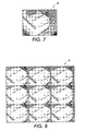
- FIGURE 7 shows an image of a textbook having planar surfaces on which a user can define a quadrilateral for text overlay to personalize the image.
- FIGURE 8 shows nine different user-defined quadrilaterals into which text has been inserted.
- FIGURE 9 shows an additional image, for which a quadrilateral is generated by clicking four points on a given image, without any visual aid or reference.
- FIGURE 10 shows another image, for which a quadrilateral is generated by clicking four points on a given image, without any visual aid or reference.
- FIGURE 11 illustrates a method for personalizing electronic images in real time, in accordance with various aspects described herein.
- the described systems and methods are applicable to Variable Information Postscript Printware (VIPP), as well as Automatic Dynamic-Object Replacement (e.g., XMPie) workflows that transmit an image a single time and subsequently only submit the variable text string to the DFE.
- VPP Variable Information Postscript Printware
- XMPie Automatic Dynamic-Object Replacement
- the described systems and methods differ from classical approaches that transmit completely individualized images separately for every data entry, which cannot be performed in real-time.
- the real time capability of the described systems and methods is achieved by adjusting the active device coordinates of a printer (e.g., inside the page description language (PDL)) and by rendering an appropriately modified data string into this temporary coordinate system.
- a printer e.g., inside the page description language (PDL)
- the systems and methods described herein thus facilitate real-time variable data image personalization that can operate in a VIPP scenario where all processing is done on the DFE at RIP-time, i.e.: at the actual time the print is generated. As such, it is distinguished from systems that require off-line processing and large data transfer (e.g., wherein each personalized image is generated and transmitted separately).
- the innovation fills a gap between high-end (compute intensive) applications and pure text-based personalization, and thus has the ability to create more attractive documents in areas that are currently not amenable to image personalization, e.g., in the trans-promotional arena.
- an image personalization system 10 that facilitates real-time generation of text overlay for an electronic image and printing of the electronic image with multiple different text strings.
- the system 10 includes a digital front end (DFE) 12 that includes a processor 14 that executes, and a memory 16 that stores, one or more sets of computer-executable instructions for carrying out the various methods and/or techniques described herein, to provide the described functionality.
- the DFE is coupled to a user interface 18 that includes a display 20.
- the user interface and DFE are further coupled to a printer 22.
- a user enters information to the user interface (e.g., using a keyboard, mouse, stylus, or some other suitable input device), and views information provided by the DFE 12 and/or the printer 22 on the display 20.
- the user interface 18 and display 20 are integral to the DFE 12 and/or to the printer 22.
- the memory 16 stores a projective (e.g., non-linear) transform 24, one or more reference rectangles 26, and one or more quadrilaterals 28 to which the reference rectangles are projected (e.g., transformed) via the projective transform.
- the memory 16 also stores one or more affine (e.g., linear) transforms 30 that fits a text string 32 into a reference rectangle 26 prior to transformation into the quadrilateral 28, thereby permitting the text 32 to be transformed or warped with the rectangle 26 for overlay a selected planar surface in an input image34 that is opened using a VIPP Designer 35 or the like.
- the modified image 36 is optionally stored to memory 16 for printing by the printer 22 and/or output on the display 20.
- the "modified” image comprises the original input image with transformed text overlaid thereon.
- the input image need not be modified. Therefore, in another example, the transformed text is stored to memory 16 and output concurrently with the input image file to generate the "modified” image.
- the plane of the reference camera is parallel to that of the object.
- the 3x3 description in homogeneous coordinates is considerably more tractable than 4x4 transforms for general objects, as is the subsequent mapping of the z-component into the 2-D paper structure because a 2-dimensional plane does not alter the visibility of any point on the plane, whereas a 3-dimensional surface will have points moving in and out of shadow (e.g., invisible) spots. These hidden areas would be handled with a complete and more complex 3-dimensional calculation.
- the projective transform 24 given by equation (1) is mapped to a page description language (PDL) file 38 (e.g., Postscript or another suitable PDL).
- PDL page description language
- a general perspective transform is not available as one of the Postscript basic matrix transform concepts. Rather, a current transform matrix (CTM) is executed via affine transforms 30 stored in the memory 16. The CTM affine transform 30 is thus used to virtually render the text 32 into a reference rectangle 26.
- Equation (1) There remains the second step of transforming the rectangle 26 into a quadrilateral 28 via the projective transform described by Equation (1).
- An additional option for geometric transformations of graphical elements in Postscript may be employed to achieve this transformation.
- the "character path" (charpath) is a native Postscript command that gives the path for the indicated string. This charpath data is transformed with the matrix of Equation (1).
- Two transforms are thus concatenated by the processor 14: the affine transform 30 (e.g. via CTM), which is a different transform for each text string, followed by the projective transform 24 (e.g., a fixed homogeneous matrix transform) applied to the charpath.
- the matrix inversion is performed to arrive at Equation (1) only once for any given background image 34, and all variable text strings 32 can re-use the same transformation. It will be appreciated, however, that, dependent on compute power, it may be more convenient to only use one transform and invert the homogenous matrix for each job record.
- FIGURE 2 illustrates a perspective projection 50 of a quadrilateral 52 having vertices ABCD from a rectangle 54 having vertices A'B'C'D', with a camera located at the origin ⁇ .
- the projection 50 represents an example of a conversion (e.g., such as may be performed by the processor 14) of the convex quadrilateral shape 52 from a rectangle 54, projected onto a flat surface that has an arbitrary orientation in 3-D space.
- the processor 14 executes the projective transform 24 to transform the quadrilateral 52 from the rectangle 54.
- perspective projections (dotted lines) for each quadrilateral vertex A,B,C,D are targeted from the origin ⁇ through respective corresponding rectangular vertices A',B',C',D'.
- the processor inverts the transform matrix from the projection.
- rectangles of arbitrary size can be created. It will be understood that the projection can also extend to the right of the quadrilateral. It will also be understood that by changing the perspective point, e.g., the origin, other aspect ratios can be achieved, and thus that the quadrilateral 52 can be mapped to any arbitrary rectangle 54. This feature permits the system 10 to map arbitrary rectangles into a given quadrilateral.
- the quadrilateral coordinates A,B,C,D e.g., the coordinates within the image on which text is to be overlaid
- PDL Postscript
- any rectangle can be transformed into the quadrilateral ABCD. Since a matrix inversion is to be performed for any rectangle A'B'C'D', it may be desirable to use a fixed reference rectangle to reduce the rendering problem to the placing of variable text into a fixed rectangular area.
- Figure 2 represents a clear deviation from existing packages since it implicitly requires the receiving quadrilateral 52 is the projection of a real rectangular object.
- the quadrilateral in the image represents an actual rectangle in the real 3-dimensional world.
- FIGURE 3 illustrates a plurality of solutions 60 to placing variable text into a fixed rectangle.
- the string "variable text” is placed into a given rectangle. For instance, in a fixed rectangle 61, the text string is stretched laterally across the fixed rectangle. In the rectangle 62, the text string is stretched vertically and laterally to fill the rectangle. In rectangle 63, the two words of the text string are placed in the rectangle in a vertical orientation relative to each other, and the word “variable” extends laterally across the width of the rectangle while both words extend vertically to fill the rectangle. In the rectangle 64, the two words of the text string are placed in the rectangle in a vertical orientation relative to each other, and both words extend laterally and vertically to fill the rectangle. In the rectangle 65, the two words of the text string are placed in the rectangle in a vertical orientation relative to each other, and extend laterally to span the width of the rectangle.
- variable data string is read from a database field.
- an aspect ratio or size of the reference rectangle that is a statistical representative of the database field can be preselected.
- a first-name field can assume a median name length of six characters (or some other suitable predetermined number of characters).
- FIGURES 4-6 illustrate various stages of an image on which text is overlaid using the herein-described techniques, to illustrate how real-time personalization of images conceptually operates inside VIPP and the VIPP Designer.
- FIGURE 4 shows an electronic image 70 of a building 72.
- a customized text string is overlaid on a planar surface of the building 72 in the image 70.
- a suitable background image is selected, which can be opened in the VIPP Designer 35 ( Figure 1 ), and the quadrilateral 28 can be hand selected or otherwise input by a user.
- FIGURE 5 shows the electronic image 70 of the building 72 with a quadrilateral 74 overlaid thereon.
- the quadrilateral 74 may be hand-drawn by a user.
- a text string may rendered, as shown in Figure 6 .
- FIGURE 6 shows the image 70 of the building 72 with a text string 76 overlaid thereon.
- the text sting reads "Joe Smith's NY City vacation photos Jul 18, 2008."
- the text may be fitted to a reference rectangle as described with regard to Figures 1 and 3 , and the reference rectangle may be transformed into the quadrilateral that overlays a selected planar surface on the building 72.
- the text in the reference rectangle is adjusted or transformed with the reference rectangle to fit into the area defined by the quadrilateral as illustrated in Figure 6 .
- the custom text 76 is overlaid on the image 70 in a user-selected region (e.g., the quadrilateral) for output to a printer or display on a user interface.
- the text string 76 is positioned in the image in visually pleasing manner, in a real-time implementation.
- the text string is overlaid onto the building, without necessarily following any building contour or texture. As such, it appears as lettering attached to the building.
- the text is single-colored without any image-dependent lighting changes.
- the user-drawn quadrilateral may be imprecise, and a close examination of the text may reveal that the text is slightly off perspective.
- the image of Figure 6 is clearly usable and has a clear personalized attribute.
- Figure 6 is a good example of the distinction of this method from previous methods, trading off the photorealistic quality for processing speed.
- the receiving surface is "flat," allowing the rendering to be done as a two step real-time transformation of mapping text into a rectangle and subsequently mapping the rectangle into the receiving quadrilateral.
- the rendered text may be restricted to simple text operations, disallowing visual effects like writing in snow, in sand, and the like.
- the text characteristics in terms of size, serif/sans-serif, font-shape, etc. is not related to other text inside the image. For example, the text attributes of the added text to a subway sign need not match precisely other text on that sign or nearby. The text attributes of the added text on a billiard table need not precisely match the other balls on the table, etc.
- the receiving image quadrilateral represents a rectangle in the actual three dimensional scene.
- this quadrilateral is automatically determined.
- the four corners of the quadrilateral are defined through direct user input.
- the four corners can be defined as four distinct points or as intersection of straight lines, etc.
- FIGURES 7-8 In order to address the "precision" with which standard users may create the quadrilateral, the examples of FIGURES 7-8 are provided below.
- the image 80 of FIGURE 7 was provided to 9 different users, who were asked to define a quadrilateral for insertion of a text string overlay.
- FIGURE 8 the name string "David Owen” was then inserted into the same picture (after the original "David Owen” string of FIGURE 7 had been erased) to give the nine results shown in Figure 8 .
- FIGURES 9 and 10 show additional images, for which a quadrilateral is generated by clicking four points on a given image, without any visual aid or reference. Variable text is then automatically rendered into the areas delineated by the user-generated quadrilaterals.
- an explicit matrix inversion may be employed.
- Figure 9 indicated the above mentioned distinction from existing computationally complex methods. As can be seen in the descenders of the letters "j", "p", and "g", no illumination change need be performed in the proposed method. The illumination change in the transition from bright sunlight to strong shadow need not be reflected in the descenders. Again, this simplification is provided to allow the described real-time rendering.
- the image renderings 110 of Figure 10 (showing multiple versions of an input image of a storefront with different text strings overlaid thereon), various different names are overlaid on the images using a VIPP-like structure (e.g., one photo and multiple name renderings thereon).
- a VIPP-like structure e.g., one photo and multiple name renderings thereon.
- the difference to existing methods is visible in the lack of illumination changes which are caused by the shadow of the tree in the storefront window.
- the resultant photo-realistic quality is sufficient as an attention getter in mass produced items, such as the combination of transactional and promotional mailings.
- FIGURE 11 illustrates a method for personalizing electronic images in real time, in accordance with various aspects described herein.
- an input image is received.
- the input image may be retrieved or selected from a database of images (e.g., pre-generated and/or updated by a user with user-captured or selected images).
- quadrilateral coordinates are received. For instance, a user may input or select vertices for a quadrilateral on a graphical display of the input image (e.g., on a computer screen or the like), where the vertices define a quadrilateral on a planar surface in the image.
- one or more text strings are read from a database for overlay on the input image. For instance, the user may input the one or more text strings into the database for overlay on the image.
- a linear transform is executed, which for each text string to position the text string in a reference rectangle (e.g., a text box).
- a non-linear transform is executed to transform the reference rectangle into the quadrilateral. That is, vertices of the reference rectangle are repositioned at corresponding vertices of the quadrilateral, to deform the rectangle into the quadrilateral.
- the file is downloaded to a printer (e.g., a marking engine or the like) for printing.
- the text string database is read N times (e.g., once for each text string), and the image is printed N times (e.g., once for each text string), such that each text string is printed in the quadrilateral on a separate instance of the image to create a modified or output image with the text strings overlaid thereon.
Abstract
Description
- The subject application relates to image personalization systems and methods. While the systems and methods described herein relate to electronic image formation in computing systems and the like, it will be appreciated that the described techniques may find application in other image formation systems, other xerographic applications, and/or other imaging methods.
- Image personalization has gained interest in recent years in print applications, and many different applications exist, among them XMPie's "ulmage," and packages by Alphapictures, and DirectSmile. The packages have a different emphasis and strengths, but all deal with complex scenes. This includes curved surfaces such as car windshields, or varying text characteristics as if written into snow, sand, leaves or the like.
- In all systems, a photorealistic result is intended, since the application area typically includes calendars, postcards and other types of artifacts that display images of natural scenes. With the existing solutions, the process of creating these personalized images is often cumbersome and complicated, requiring a high level of skill and experience on the part of the designer, or the use of preselected photos. Moreover, sophisticated rendering effects place considerable demands on computation and storage, and thus must be either carried out offline, or by dedicated high-end servers.
- All three of the aforementioned packages produce high quality artifacts in their application domain, but none of them is applicable to real-time, digital front end (DFE)-based processing and printing and are thus normally not part of the print-generating Raster Image processor (RIP). This is also caused by the large data amount that has to be communicated to the machine (e.g., each image is unique and transmitted separately). Approaches exist to transmit image sections, but these have their own set of unique problems. Here and in the following the term "real-time" is used to indicate a processing speed comparable to the actual print speed of the output device.
- Accordingly, there is an unmet need for systems and/or methods that create a variable data image in a simple fashion, and that does not require additional data transfer or upstream processing, while overcoming the aforementioned deficiencies.
- In accordance with various aspects described herein, systems and methods are described that facilitate the creation of personalized images in a simple and fast way. For example, a method of real-time personalization of an electronic image for printing comprise receiving input coordinates for vertices of a quadrilateral deemed to lie on a planar surface represented in an electronic image, reading one or more variable text strings from a database, and performing an affine transform to fit each text string into a rectangular text box. The method further comprises performing a non-linear projective transform on the rectangular text box to move vertices of the rectangular text box to the vertices of the quadrilateral, and rendering each transformed text string in the quadrilateral on a respective version on the electronic image.
- According to another feature described herein, a system that facilitates performing real-time personalization of electronic images comprises a processor that executes computer-executable instructions stored to a memory, including instructions for receiving input coordinates for vertices of a quadrilateral deemed to lie on a planar surface represented in an electronic image and for reading one or more variable text strings from a database. The processor further executes instructions for executing an affine transform to fit each text string into a rectangular text box, performing a non-linear projective transform on the rectangular text box to move vertices of the rectangular text box to the vertices of the quadrilateral, and rendering each transformed text string in its quadrilateral on a respective version on the electronic image. The system further comprises a printer that prints the electronic image with the text string positioned in the quadrilateral on the electronic image.
- Yet another feature relates to a method of personalizing an electronic image comprises identifying a planar surface in the image, delineating a quadrilateral on the planar surface, and inserting a variable text string into a rectangular text box using an affine transform. The method further comprises projecting the text box into the quadrilateral using a non-linear transform, and rendering the projected text onto the planar surface in the image and outputting a modified electronic image.
In a further embodiment the affine transform is performed iteratively for a plurality of text strings, and further comprising outputting a plurality of modified electronic images with respective text strings overlaid thereon. - In a further embodiment the modified electronic image is output to a user interface and displayed thereon.
- In a further embodiment the modified electronic image is output to a printing device and printed thereby.
-
FIGURE 1 illustrates an image personalization system is illustrated that facilitates real-time generation of text overlay for an electronic image and printing of the electronic image with multiple different text strings. -
FIGURE 2 illustrates a perspective projection of a quadrilateral having vertices ABCD from a rectangle having vertices A'B'C'D', with a camera located at the origin Ω. -
FIGURE 3 illustrates a plurality of solutions to placing variable text into a fixed rectangle. -
FIGURE 4 shows an electronic image of a building. -
FIGURE 5 shows the electronic image of the building with a quadrilateral overlaid thereon. -
FIGURE 6 shows the image of the building with a text string overlaid thereon. -
FIGURE 7 shows an image of a textbook having planar surfaces on which a user can define a quadrilateral for text overlay to personalize the image. -
FIGURE 8 shows nine different user-defined quadrilaterals into which text has been inserted. -
FIGURE 9 shows an additional image, for which a quadrilateral is generated by clicking four points on a given image, without any visual aid or reference. -
FIGURE 10 shows another image, for which a quadrilateral is generated by clicking four points on a given image, without any visual aid or reference. -
FIGURE 11 illustrates a method for personalizing electronic images in real time, in accordance with various aspects described herein. - In accordance with various features described herein, systems and methods are described that overcome the above-described problems by restricting the rendering to "flat" (i.e. planar) surfaces, permitting (without requiring) the variable data to be photorealistic, and by approximating some of the transform data with a simple non-physical derivation. In this manner, a real-time 3-D approximation is generated that is sufficiently realistic to catch the eye, but that is also extremely simple to create and compute, thus enabling RIP/DFE implementation. That is, a realistic text overlay for an image is generated in real-time, where "realistic" refers to the geometric structure, omitting texture, lighting and other higher order elements. The described systems and methods are applicable to Variable Information Postscript Printware (VIPP), as well as Automatic Dynamic-Object Replacement (e.g., XMPie) workflows that transmit an image a single time and subsequently only submit the variable text string to the DFE. In this manner, the described systems and methods differ from classical approaches that transmit completely individualized images separately for every data entry, which cannot be performed in real-time. The real time capability of the described systems and methods is achieved by adjusting the active device coordinates of a printer (e.g., inside the page description language (PDL)) and by rendering an appropriately modified data string into this temporary coordinate system.
- The systems and methods described herein thus facilitate real-time variable data image personalization that can operate in a VIPP scenario where all processing is done on the DFE at RIP-time, i.e.: at the actual time the print is generated. As such, it is distinguished from systems that require off-line processing and large data transfer (e.g., wherein each personalized image is generated and transmitted separately). Thus, the innovation fills a gap between high-end (compute intensive) applications and pure text-based personalization, and thus has the ability to create more attractive documents in areas that are currently not amenable to image personalization, e.g., in the trans-promotional arena.
- With reference to FGURE 1, an
image personalization system 10 is illustrated that facilitates real-time generation of text overlay for an electronic image and printing of the electronic image with multiple different text strings. Thesystem 10 includes a digital front end (DFE) 12 that includes aprocessor 14 that executes, and amemory 16 that stores, one or more sets of computer-executable instructions for carrying out the various methods and/or techniques described herein, to provide the described functionality. The DFE is coupled to auser interface 18 that includes adisplay 20. The user interface and DFE are further coupled to aprinter 22. A user enters information to the user interface (e.g., using a keyboard, mouse, stylus, or some other suitable input device), and views information provided by the DFE 12 and/or theprinter 22 on thedisplay 20. According to one aspect, theuser interface 18 anddisplay 20 are integral to the DFE 12 and/or to theprinter 22. - The
memory 16 stores a projective (e.g., non-linear) transform 24, one ormore reference rectangles 26, and one or more quadrilaterals 28 to which the reference rectangles are projected (e.g., transformed) via the projective transform. Thememory 16 also stores one or more affine (e.g., linear) transforms 30 that fits atext string 32 into areference rectangle 26 prior to transformation into the quadrilateral 28, thereby permitting thetext 32 to be transformed or warped with therectangle 26 for overlay a selected planar surface in an input image34 that is opened using a VIPPDesigner 35 or the like. Once the transformed text has been overlaid on theinput image 34, the modified image 36 is optionally stored tomemory 16 for printing by theprinter 22 and/or output on thedisplay 20. The "modified" image comprises the original input image with transformed text overlaid thereon. Other than the overlay of the transformed text, the input image need not be modified. Therefore, in another example, the transformed text is stored tomemory 16 and output concurrently with the input image file to generate the "modified" image. - According to an example that relates to planar objects inside a photograph or scene (e.g., in an electronic image), the geometric transform of a plane to an arbitrary viewpoint or camera point can be described by the well known
projective transform 24 that is executed by theprocessor 14, and which is stored in thememory 16, as:
where (x, y) is the location of a point on the plane with respect to a first or reference camera viewpoint, and (x', y') is the location of that same point with respect to a second camera viewpoint. Without loss of generality, it may be assumed that the plane of the reference camera is parallel to that of the object. The 3x3 description in homogeneous coordinates is considerably more tractable than 4x4 transforms for general objects, as is the subsequent mapping of the z-component into the 2-D paper structure because a 2-dimensional plane does not alter the visibility of any point on the plane, whereas a 3-dimensional surface will have points moving in and out of shadow (e.g., invisible) spots. These hidden areas would be handled with a complete and more complex 3-dimensional calculation. - Since the entire personalized image approach is a real-time (e.g., VIPP) process, the
projective transform 24 given by equation (1) is mapped to a page description language (PDL) file 38 (e.g., Postscript or another suitable PDL). In this context, a general perspective transform is not available as one of the Postscript basic matrix transform concepts. Rather, a current transform matrix (CTM) is executed via affine transforms 30 stored in thememory 16. The CTM affine transform 30 is thus used to virtually render thetext 32 into areference rectangle 26. - There remains the second step of transforming the
rectangle 26 into a quadrilateral 28 via the projective transform described by Equation (1). An additional option for geometric transformations of graphical elements in Postscript may be employed to achieve this transformation. Specifically for text, the "character path" (charpath) is a native Postscript command that gives the path for the indicated string. This charpath data is transformed with the matrix of Equation (1). - Two transforms are thus concatenated by the processor 14: the affine transform 30 (e.g. via CTM), which is a different transform for each text string, followed by the projective transform 24 (e.g., a fixed homogeneous matrix transform) applied to the charpath. In this way, the matrix inversion is performed to arrive at Equation (1) only once for any given
background image 34, and all variable text strings 32 can re-use the same transformation. It will be appreciated, however, that, dependent on compute power, it may be more convenient to only use one transform and invert the homogenous matrix for each job record. - With continued reference to
Figure 1 ,FIGURE 2 illustrates aperspective projection 50 of a quadrilateral 52 having vertices ABCD from arectangle 54 having vertices A'B'C'D', with a camera located at the origin Ω. Theprojection 50 represents an example of a conversion (e.g., such as may be performed by the processor 14) of the convexquadrilateral shape 52 from arectangle 54, projected onto a flat surface that has an arbitrary orientation in 3-D space. In one example, theprocessor 14 executes theprojective transform 24 to transform the quadrilateral 52 from therectangle 54. In this example, perspective projections (dotted lines) for each quadrilateral vertex A,B,C,D are targeted from the origin Ω through respective corresponding rectangular vertices A',B',C',D'. In another example, the processor inverts the transform matrix from the projection. - For a given perspective point, rectangles of arbitrary size, but constant aspect ratio, can be created. It will be understood that the projection can also extend to the right of the quadrilateral. It will also be understood that by changing the perspective point, e.g., the origin, other aspect ratios can be achieved, and thus that the quadrilateral 52 can be mapped to any
arbitrary rectangle 54. This feature permits thesystem 10 to map arbitrary rectangles into a given quadrilateral. For the inversion of the transformation matrix, the quadrilateral coordinates A,B,C,D (e.g., the coordinates within the image on which text is to be overlaid) are determined or retrieved, as are the coordinates of an arbitrary rectangle, which is selected based on other convenient parameters. Such parameters are clarified in the Postscript (PDL) part of the projection. - As noted above, any rectangle can be transformed into the quadrilateral ABCD. Since a matrix inversion is to be performed for any rectangle A'B'C'D', it may be desirable to use a fixed reference rectangle to reduce the rendering problem to the placing of variable text into a fixed rectangular area.
- It should be noted that
Figure 2 represents a clear deviation from existing packages since it implicitly requires the receivingquadrilateral 52 is the projection of a real rectangular object. In other words, the quadrilateral in the image represents an actual rectangle in the real 3-dimensional world. -
FIGURE 3 illustrates a plurality ofsolutions 60 to placing variable text into a fixed rectangle. The string "variable text" is placed into a given rectangle. For instance, in a fixedrectangle 61, the text string is stretched laterally across the fixed rectangle. In therectangle 62, the text string is stretched vertically and laterally to fill the rectangle. Inrectangle 63, the two words of the text string are placed in the rectangle in a vertical orientation relative to each other, and the word "variable" extends laterally across the width of the rectangle while both words extend vertically to fill the rectangle. In therectangle 64, the two words of the text string are placed in the rectangle in a vertical orientation relative to each other, and both words extend laterally and vertically to fill the rectangle. In therectangle 65, the two words of the text string are placed in the rectangle in a vertical orientation relative to each other, and extend laterally to span the width of the rectangle. - From
Figure 3 it is clear that the described approach need not yield a unique answer, since therectangles 61 through 65 will be mapped into a quadrilateral just asrectangle 54 ofFigure 2 is mapped intoquadrilateral 52. In this manner real-time processing is enabled. In essence, the approach shown here is limited to standard fonts on a flat surface, such that an exact determine of text aspect ratio need not be performed since the text-receiving surface is flat. - The five different solutions of
Figure 3 are "valid" solutions in a mathematical sense. Depending on a given application one such solution may be preferred over another by a user. It will be noted that in Postscript, full access to the aspect ratio of the input string is available for any pre-specified font, as well as access to information indicating whether there are any "blank" characters in the text string. Anamorphic scaling can thus be limited to a given range, and switching between different scalings based on that information is possible. Additionally, a blank character in the text string can be replaced with a line break, if desired. - In VIPP applications, the variable data string is read from a database field. Accordingly, an aspect ratio or size of the reference rectangle that is a statistical representative of the database field can be preselected. For example, a first-name field can assume a median name length of six characters (or some other suitable predetermined number of characters). In another example, an estimate for the aspect ratio can be derived from the quadrilateral as:

- These choices and the exemplary renderings of
Figure 3 can be supplied to the user or designer via theuser interface 18, e.g. as part of the VIPP ProPublisher. Fitting the text into the rectangle is standard VIPP/Postscript functionality. The scaling methods or techniques used to generate the solutions ofFigure 3 optionally can be included as a field attribute. -
FIGURES 4-6 illustrate various stages of an image on which text is overlaid using the herein-described techniques, to illustrate how real-time personalization of images conceptually operates inside VIPP and the VIPP Designer. -
FIGURE 4 shows anelectronic image 70 of abuilding 72. Using the described systems and methods, a customized text string is overlaid on a planar surface of thebuilding 72 in theimage 70. Thus, as a first step, a suitable background image is selected, which can be opened in the VIPP Designer 35 (Figure 1 ), and the quadrilateral 28 can be hand selected or otherwise input by a user. -
FIGURE 5 shows theelectronic image 70 of thebuilding 72 with a quadrilateral 74 overlaid thereon. The quadrilateral 74 may be hand-drawn by a user. Into the quadrilateral 74, a text string may rendered, as shown inFigure 6 . -
FIGURE 6 shows theimage 70 of thebuilding 72 with atext string 76 overlaid thereon. The text sting reads "Joe Smith's NY Cityvacation photos Jul 18, 2008." For instance, the text may be fitted to a reference rectangle as described with regard toFigures 1 and3 , and the reference rectangle may be transformed into the quadrilateral that overlays a selected planar surface on thebuilding 72. The text in the reference rectangle is adjusted or transformed with the reference rectangle to fit into the area defined by the quadrilateral as illustrated inFigure 6 . In this manner, thecustom text 76 is overlaid on theimage 70 in a user-selected region (e.g., the quadrilateral) for output to a printer or display on a user interface. - As can be seen from
Figure 6 , thetext string 76 is positioned in the image in visually pleasing manner, in a real-time implementation. For example, the text string is overlaid onto the building, without necessarily following any building contour or texture. As such, it appears as lettering attached to the building. Additionally, in this example, the text is single-colored without any image-dependent lighting changes. Moreover, the user-drawn quadrilateral may be imprecise, and a close examination of the text may reveal that the text is slightly off perspective. However, the image ofFigure 6 is clearly usable and has a clear personalized attribute. At the same time, however,Figure 6 is a good example of the distinction of this method from previous methods, trading off the photorealistic quality for processing speed. - The description thus far illustrates how a real-time 3D photorealistic rendering can be approximated if certain simplifications are made. Firstly, the receiving surface is "flat," allowing the rendering to be done as a two step real-time transformation of mapping text into a rectangle and subsequently mapping the rectangle into the receiving quadrilateral. Secondly, the rendered text may be restricted to simple text operations, disallowing visual effects like writing in snow, in sand, and the like. Thirdly, the text characteristics in terms of size, serif/sans-serif, font-shape, etc., is not related to other text inside the image. For example, the text attributes of the added text to a subway sign need not match precisely other text on that sign or nearby. The text attributes of the added text on a billiard table need not precisely match the other balls on the table, etc. Fourthly, the receiving image quadrilateral represents a rectangle in the actual three dimensional scene.
- These four restrictions distinguish the resulting images from the images created in an elaborate system in terms of visual appearance, but as mentioned earlier, they also permit real-time processing on common DFE/RIP systems and thus are advantageous in many situations.
- In the above description, no mention has been made about the initial definition of the quadrilateral inside the image. In one example, this quadrilateral is automatically determined. In another example, the four corners of the quadrilateral are defined through direct user input. Here, it is understood that the four corners can be defined as four distinct points or as intersection of straight lines, etc. Thus various user interactions exist that result in the definition of four points for the subsequent processing.
- In order to address the "precision" with which standard users may create the quadrilateral, the examples of
FIGURES 7-8 are provided below. Theimage 80 ofFIGURE 7 was provided to 9 different users, who were asked to define a quadrilateral for insertion of a text string overlay. InFIGURE 8 , the name string "David Owen" was then inserted into the same picture (after the original "David Owen" string ofFIGURE 7 had been erased) to give the nine results shown inFigure 8 . - Closer examination of
Figure 8 shows that some examples are imperfect with respect to the geometry, such as the lower-middle representation. However, all nine renditions are still very useful (e.g., in a trans-promo application or the like). -
FIGURES 9 and10 show additional images, for which a quadrilateral is generated by clicking four points on a given image, without any visual aid or reference. Variable text is then automatically rendered into the areas delineated by the user-generated quadrilaterals. In this example, an explicit matrix inversion may be employed. In the modifiedimage renderings 100 ofFigure 9 (showing multiple versions of an input image of a balcony with different text strings overlaid thereon).Figure 9 indicated the above mentioned distinction from existing computationally complex methods. As can be seen in the descenders of the letters "j", "p", and "g", no illumination change need be performed in the proposed method. The illumination change in the transition from bright sunlight to strong shadow need not be reflected in the descenders. Again, this simplification is provided to allow the described real-time rendering. - The
image renderings 110 ofFigure 10 (showing multiple versions of an input image of a storefront with different text strings overlaid thereon), various different names are overlaid on the images using a VIPP-like structure (e.g., one photo and multiple name renderings thereon). As inFigure 9 , the difference to existing methods is visible in the lack of illumination changes which are caused by the shadow of the tree in the storefront window. However, just like inFigure 9 , the resultant photo-realistic quality is sufficient as an attention getter in mass produced items, such as the combination of transactional and promotional mailings. -
FIGURE 11 illustrates a method for personalizing electronic images in real time, in accordance with various aspects described herein. At 120, an input image is received. The input image may be retrieved or selected from a database of images (e.g., pre-generated and/or updated by a user with user-captured or selected images). At 122, quadrilateral coordinates are received. For instance, a user may input or select vertices for a quadrilateral on a graphical display of the input image (e.g., on a computer screen or the like), where the vertices define a quadrilateral on a planar surface in the image. At 124, one or more text strings are read from a database for overlay on the input image. For instance, the user may input the one or more text strings into the database for overlay on the image. - At 126, a linear transform is executed, which for each text string to position the text string in a reference rectangle (e.g., a text box). At 128, a non-linear transform is executed to transform the reference rectangle into the quadrilateral. That is, vertices of the reference rectangle are repositioned at corresponding vertices of the quadrilateral, to deform the rectangle into the quadrilateral. At 130, the file is downloaded to a printer (e.g., a marking engine or the like) for printing. At 132, the text string database is read N times (e.g., once for each text string), and the image is printed N times (e.g., once for each text string), such that each text string is printed in the quadrilateral on a separate instance of the image to create a modified or output image with the text strings overlaid thereon.
- It will be appreciated that various of the above-disclosed and other features and functions, or alternatives thereof, may be desirably combined into many other different systems or applications.
Claims (15)
- A method of real-time personalization of an electronic image for printing, comprising:receiving input coordinates for vertices of a quadrilateral deemed to lie on a planar surface represented in an electronic image;reading one or more variable text strings from a database;performing an affine transform to fit each text string into a rectangular text box;performing a non-linear projective transform on the rectangular text box to move vertices of the rectangular text box to the vertices of the quadrilateral; andrendering each transformed text string in the quadrilateral on a respective version on the electronic image.
- The method of claim 1, further comprising:storing the one or more variable text strings in a spreadsheet database;sequentially reading the one or more text strings from the spreadsheet; andperforming the affine transform on each text string to fit each respective text string into its respective rectangular text box.
- The method of claim 1, wherein the non-linear projective transform is described by the equation:

where (x, y) is the location of a point on the plane with respect to a first or reference camera viewpoint, and (x', y') is the location of that same point with respect to a second camera viewpoint. - The method of claim 3, further comprising executing the non-linear projective transform given by equation (1) within a page description language (PDL) file.
- The method of claim 4, further comprising downloading the PDL file to a printer for printing each transformed text string in the quadrilateral on the respective version on the electronic image.
- The method of claim 1, stored as a set of computer-executable instructions in an electronic storage medium, and executed by a processor in a digital front end (DFE) of a printer.
- A system that facilitates performing real-time personalization of electronic images, comprising:a processor that executes computer-executable instructions stored to a memory, including instructions for:receiving input coordinates for vertices of a quadrilateral deemed to lie on a planar surface represented in an electronic image;reading one or more variable text strings from a database;executing an affine transform to fit each text string into a rectangular text box;performing a non-linear projective transform on the rectangular text box to move vertices of the rectangular text box to the vertices of the quadrilateral; andrendering each transformed text string in its quadrilateral on a respective version on the electronic image; anda printer that prints the electronic image with the text string positioned in the quadrilateral on the electronic image.
- The system of claim 7, wherein the one or more text strings is stored in a spreadsheet database, and
wherein the processor sequentially reads the one or more text strings from the spreadsheet and performs the affine transform on each text string to fit each text string into its respective rectangular text box. - The system of claim 7, wherein the non-linear projective transform is described by the equation:

where (x, y) is the location of a point on the plane with respect to a first or reference camera viewpoint, and (x', y') is the location of that same point with respect to a second camera viewpoint. - The system of claim 9, wherein the processor executes the non-linear projective transform given by equation (1) within a page description language (PDL) file.
- The system of claim 10, wherein the processor downloads the PDL file to the printer for printing each text string in the quadrilateral on the respective version on the electronic image.
- The system of claim 7, wherein the processor is located in a digital front end (DFE) of the printer.
- The system of claim 7, wherein the processor outputs the electronic images with respective text strings overlaid thereon to the memory for subsequent recall by the printer.
- The system of claim 7, wherein the processor outputs the electronic images with respective text strings overlaid thereon directly to the printer for printing.
- A method of personalizing an electronic image, comprising:identifying a planar surface in the image;delineating a quadrilateral on the planar surface;inserting a variable text string into a rectangular text box using an affine transform;projecting the text box into the quadrilateral using a non-linear transform; andrendering the projected text onto the planar surface in the image and outputting a modified electronic image.
Applications Claiming Priority (1)
| Application Number | Priority Date | Filing Date | Title |
|---|---|---|---|
| US12/475,748 US8244070B2 (en) | 2009-06-01 | 2009-06-01 | Real-time image personalization |
Publications (3)
| Publication Number | Publication Date |
|---|---|
| EP2261860A2 true EP2261860A2 (en) | 2010-12-15 |
| EP2261860A3 EP2261860A3 (en) | 2011-08-10 |
| EP2261860B1 EP2261860B1 (en) | 2013-03-27 |
Family
ID=42664780
Family Applications (1)
| Application Number | Title | Priority Date | Filing Date |
|---|---|---|---|
| EP10164202A Not-in-force EP2261860B1 (en) | 2009-06-01 | 2010-05-28 | Real-time image personalization |
Country Status (3)
| Country | Link |
|---|---|
| US (1) | US8244070B2 (en) |
| EP (1) | EP2261860B1 (en) |
| JP (1) | JP5307761B2 (en) |
Families Citing this family (20)
| Publication number | Priority date | Publication date | Assignee | Title |
|---|---|---|---|---|
| US8780131B2 (en) * | 2008-12-19 | 2014-07-15 | Xerox Corporation | Systems and methods for text-based personalization of images |
| US8619074B2 (en) | 2010-12-10 | 2013-12-31 | Xerox Corporation | Rendering personalized text on curved image surfaces |
| US8805056B2 (en) | 2011-01-24 | 2014-08-12 | Xerox Corporation | Automatic detection and grouping of straight lines in images for personalization |
| CN102156688B (en) * | 2011-05-19 | 2012-12-12 | 深圳市万兴软件有限公司 | Character transforming effect processing method and device |
| US8935259B2 (en) | 2011-06-20 | 2015-01-13 | Google Inc | Text suggestions for images |
| US9361283B2 (en) * | 2011-11-30 | 2016-06-07 | Google Inc. | Method and system for projecting text onto surfaces in geographic imagery |
| US9042640B2 (en) * | 2012-01-13 | 2015-05-26 | Xerox Corporation | Methods and system for analyzing and rating images for personalization |
| US8837830B2 (en) * | 2012-06-12 | 2014-09-16 | Xerox Corporation | Finding text in natural scenes |
| JP2014035656A (en) * | 2012-08-09 | 2014-02-24 | Sony Corp | Image processing apparatus, image processing method, and program |
| JP5553423B1 (en) * | 2013-01-31 | 2014-07-16 | 株式会社精美堂 | Calendar, its creation method, and calendar creation system |
| JP5769768B2 (en) * | 2013-09-03 | 2015-08-26 | オリンパス株式会社 | Imaging apparatus, imaging method, and program |
| US10049477B1 (en) * | 2014-06-27 | 2018-08-14 | Google Llc | Computer-assisted text and visual styling for images |
| JP5964937B2 (en) * | 2014-12-05 | 2016-08-03 | オリンパス株式会社 | Image processing method, electronic device, and program |
| JP6063971B2 (en) * | 2015-01-29 | 2017-01-18 | 京セラドキュメントソリューションズ株式会社 | Image processing device |
| US9940557B2 (en) * | 2016-02-08 | 2018-04-10 | Xerox Corporation | Document printing using hardware-dependent fonts |
| WO2018176040A1 (en) * | 2017-03-24 | 2018-09-27 | Pti Marketing Technologies Inc. | Systems and methods for clipping images |
| DK201870353A1 (en) * | 2018-05-07 | 2019-12-04 | Apple Inc. | User interfaces for recommending and consuming content on an electronic device |
| US10331966B1 (en) * | 2018-10-19 | 2019-06-25 | Capital One Services, Llc | Image processing to detect a rectangular object |
| CN114730580A (en) | 2019-11-11 | 2022-07-08 | 苹果公司 | User interface for time period based cull playlist |
| CN111625237B (en) * | 2020-04-30 | 2023-05-30 | 上海艾麒信息科技有限公司 | Character vision deformation method, system and medium |
Family Cites Families (8)
| Publication number | Priority date | Publication date | Assignee | Title |
|---|---|---|---|---|
| US5995724A (en) | 1996-11-01 | 1999-11-30 | Mikkelsen; Carl | Image process system and process using personalization techniques |
| JP3967036B2 (en) * | 1999-04-06 | 2007-08-29 | 大日本印刷株式会社 | Image synthesizer |
| US8121338B2 (en) | 2004-07-07 | 2012-02-21 | Directsmile Gmbh | Process for generating images with realistic text insertion |
| JP4155322B2 (en) * | 2006-09-25 | 2008-09-24 | コニカミノルタビジネステクノロジーズ株式会社 | Image processing apparatus, image processing method, and image processing program |
| US7877706B2 (en) * | 2007-01-12 | 2011-01-25 | International Business Machines Corporation | Controlling a document based on user behavioral signals detected from a 3D captured image stream |
| AU2008226843A1 (en) * | 2007-03-08 | 2008-09-18 | Microscan Systems, Inc. | Detection and segmentation of a two-dimensional code |
| US7978364B2 (en) | 2007-06-18 | 2011-07-12 | Canon Kabushiki Kaisha | Image processing apparatus and control method thereof |
| JP5035614B2 (en) * | 2007-09-26 | 2012-09-26 | カシオ計算機株式会社 | Imaging apparatus and program |
-
2009
- 2009-06-01 US US12/475,748 patent/US8244070B2/en active Active
-
2010
- 2010-05-27 JP JP2010121194A patent/JP5307761B2/en not_active Expired - Fee Related
- 2010-05-28 EP EP10164202A patent/EP2261860B1/en not_active Not-in-force
Non-Patent Citations (1)
| Title |
|---|
| JOE SMITH'S NY CITY VACATION PHOTOS, 18 July 2008 (2008-07-18) |
Also Published As
| Publication number | Publication date |
|---|---|
| JP5307761B2 (en) | 2013-10-02 |
| US8244070B2 (en) | 2012-08-14 |
| EP2261860B1 (en) | 2013-03-27 |
| EP2261860A3 (en) | 2011-08-10 |
| US20100302594A1 (en) | 2010-12-02 |
| JP2010279038A (en) | 2010-12-09 |
Similar Documents
| Publication | Publication Date | Title |
|---|---|---|
| EP2261860B1 (en) | Real-time image personalization | |
| US6124858A (en) | Raster image mapping | |
| US8866841B1 (en) | Method and apparatus to deliver imagery with embedded data | |
| AU2009209293B2 (en) | Representing flat designs to be printed on curves of a 3-dimensional product | |
| EP0950988B1 (en) | Three-Dimensional image generating apparatus | |
| US8130238B2 (en) | Methods and files for delivering imagery with embedded data | |
| US11049307B2 (en) | Transferring vector style properties to a vector artwork | |
| US7412360B2 (en) | Method and apparatus for shape deformation and placement | |
| US8005316B1 (en) | System and method for editing image data for media repurposing | |
| US20100011281A1 (en) | Systems and mehtods for annotating pages of a 3d electronic document | |
| US20090153555A1 (en) | System and Computer-Implemented Method for Modeling the Three-Dimensional Shape of An Object by Shading of a Two-Dimensional Image of the Object | |
| US20110069071A1 (en) | 3D Virtual Environment for Generating Variable Data Images | |
| Anderson et al. | Unwrapping and visualizing cuneiform tablets | |
| US6724383B1 (en) | System and computer-implemented method for modeling the three-dimensional shape of an object by shading of a two-dimensional image of the object | |
| US7764291B1 (en) | Identification of common visible regions in purposing media for targeted use | |
| EP1922700B1 (en) | 2d/3d combined rendering | |
| US11126788B2 (en) | Font capture from images of target decorative character glyphs | |
| US20060251290A1 (en) | Method and system for composing a digital signature graphic appearance and specifying a document display location thereof | |
| US20130050215A1 (en) | Apparatus and method for 3d font engine | |
| Coutts et al. | Rendering with streamlines. | |
| Surazhsky et al. | Artistic surface rendering using layout of text | |
| Mihajlović et al. | Application and Difference of Raster and Vector Graphics | |
| JP2006113800A (en) | Image processing method, image processing device, and image processing program | |
| JPS6210773A (en) | Two-dimensional representation of solid container attached with character | |
| JP2004030402A (en) | Image editing apparatus and storage medium |
Legal Events
| Date | Code | Title | Description |
|---|---|---|---|
| PUAI | Public reference made under article 153(3) epc to a published international application that has entered the european phase |
Free format text: ORIGINAL CODE: 0009012 |
|
| AK | Designated contracting states |
Kind code of ref document: A2 Designated state(s): AL AT BE BG CH CY CZ DE DK EE ES FI FR GB GR HR HU IE IS IT LI LT LU LV MC MK MT NL NO PL PT RO SE SI SK SM TR |
|
| AX | Request for extension of the european patent |
Extension state: BA ME RS |
|
| PUAL | Search report despatched |
Free format text: ORIGINAL CODE: 0009013 |
|
| AK | Designated contracting states |
Kind code of ref document: A3 Designated state(s): AL AT BE BG CH CY CZ DE DK EE ES FI FR GB GR HR HU IE IS IT LI LT LU LV MC MK MT NL NO PL PT RO SE SI SK SM TR |
|
| AX | Request for extension of the european patent |
Extension state: BA ME RS |
|
| RIC1 | Information provided on ipc code assigned before grant |
Ipc: G06T 11/60 20060101AFI20110704BHEP |
|
| 17P | Request for examination filed |
Effective date: 20120210 |
|
| GRAP | Despatch of communication of intention to grant a patent |
Free format text: ORIGINAL CODE: EPIDOSNIGR1 |
|
| GRAS | Grant fee paid |
Free format text: ORIGINAL CODE: EPIDOSNIGR3 |
|
| GRAP | Despatch of communication of intention to grant a patent |
Free format text: ORIGINAL CODE: EPIDOSNIGR1 |
|
| GRAA | (expected) grant |
Free format text: ORIGINAL CODE: 0009210 |
|
| AK | Designated contracting states |
Kind code of ref document: B1 Designated state(s): AL AT BE BG CH CY CZ DE DK EE ES FI FR GB GR HR HU IE IS IT LI LT LU LV MC MK MT NL NO PL PT RO SE SI SK SM TR |
|
| REG | Reference to a national code |
Ref country code: GB Ref legal event code: FG4D |
|
| REG | Reference to a national code |
Ref country code: CH Ref legal event code: EP |
|
| REG | Reference to a national code |
Ref country code: AT Ref legal event code: REF Ref document number: 603828 Country of ref document: AT Kind code of ref document: T Effective date: 20130415 |
|
| REG | Reference to a national code |
Ref country code: IE Ref legal event code: FG4D |
|
| REG | Reference to a national code |
Ref country code: DE Ref legal event code: R096 Ref document number: 602010005726 Country of ref document: DE Effective date: 20130523 |
|
| PG25 | Lapsed in a contracting state [announced via postgrant information from national office to epo] |
Ref country code: BG Free format text: LAPSE BECAUSE OF FAILURE TO SUBMIT A TRANSLATION OF THE DESCRIPTION OR TO PAY THE FEE WITHIN THE PRESCRIBED TIME-LIMIT Effective date: 20130627 Ref country code: SE Free format text: LAPSE BECAUSE OF FAILURE TO SUBMIT A TRANSLATION OF THE DESCRIPTION OR TO PAY THE FEE WITHIN THE PRESCRIBED TIME-LIMIT Effective date: 20130327 Ref country code: NO Free format text: LAPSE BECAUSE OF FAILURE TO SUBMIT A TRANSLATION OF THE DESCRIPTION OR TO PAY THE FEE WITHIN THE PRESCRIBED TIME-LIMIT Effective date: 20130627 Ref country code: LT Free format text: LAPSE BECAUSE OF FAILURE TO SUBMIT A TRANSLATION OF THE DESCRIPTION OR TO PAY THE FEE WITHIN THE PRESCRIBED TIME-LIMIT Effective date: 20130327 |
|
| REG | Reference to a national code |
Ref country code: AT Ref legal event code: MK05 Ref document number: 603828 Country of ref document: AT Kind code of ref document: T Effective date: 20130327 |
|
| REG | Reference to a national code |
Ref country code: LT Ref legal event code: MG4D |
|
| PG25 | Lapsed in a contracting state [announced via postgrant information from national office to epo] |
Ref country code: LV Free format text: LAPSE BECAUSE OF FAILURE TO SUBMIT A TRANSLATION OF THE DESCRIPTION OR TO PAY THE FEE WITHIN THE PRESCRIBED TIME-LIMIT Effective date: 20130327 Ref country code: GR Free format text: LAPSE BECAUSE OF FAILURE TO SUBMIT A TRANSLATION OF THE DESCRIPTION OR TO PAY THE FEE WITHIN THE PRESCRIBED TIME-LIMIT Effective date: 20130628 Ref country code: FI Free format text: LAPSE BECAUSE OF FAILURE TO SUBMIT A TRANSLATION OF THE DESCRIPTION OR TO PAY THE FEE WITHIN THE PRESCRIBED TIME-LIMIT Effective date: 20130327 Ref country code: SI Free format text: LAPSE BECAUSE OF FAILURE TO SUBMIT A TRANSLATION OF THE DESCRIPTION OR TO PAY THE FEE WITHIN THE PRESCRIBED TIME-LIMIT Effective date: 20130327 |
|
| REG | Reference to a national code |
Ref country code: NL Ref legal event code: VDEP Effective date: 20130327 |
|
| PG25 | Lapsed in a contracting state [announced via postgrant information from national office to epo] |
Ref country code: HR Free format text: LAPSE BECAUSE OF FAILURE TO SUBMIT A TRANSLATION OF THE DESCRIPTION OR TO PAY THE FEE WITHIN THE PRESCRIBED TIME-LIMIT Effective date: 20130327 Ref country code: BE Free format text: LAPSE BECAUSE OF FAILURE TO SUBMIT A TRANSLATION OF THE DESCRIPTION OR TO PAY THE FEE WITHIN THE PRESCRIBED TIME-LIMIT Effective date: 20130327 |
|
| PG25 | Lapsed in a contracting state [announced via postgrant information from national office to epo] |
Ref country code: EE Free format text: LAPSE BECAUSE OF FAILURE TO SUBMIT A TRANSLATION OF THE DESCRIPTION OR TO PAY THE FEE WITHIN THE PRESCRIBED TIME-LIMIT Effective date: 20130327 Ref country code: ES Free format text: LAPSE BECAUSE OF FAILURE TO SUBMIT A TRANSLATION OF THE DESCRIPTION OR TO PAY THE FEE WITHIN THE PRESCRIBED TIME-LIMIT Effective date: 20130708 Ref country code: CZ Free format text: LAPSE BECAUSE OF FAILURE TO SUBMIT A TRANSLATION OF THE DESCRIPTION OR TO PAY THE FEE WITHIN THE PRESCRIBED TIME-LIMIT Effective date: 20130327 Ref country code: SK Free format text: LAPSE BECAUSE OF FAILURE TO SUBMIT A TRANSLATION OF THE DESCRIPTION OR TO PAY THE FEE WITHIN THE PRESCRIBED TIME-LIMIT Effective date: 20130327 Ref country code: NL Free format text: LAPSE BECAUSE OF FAILURE TO SUBMIT A TRANSLATION OF THE DESCRIPTION OR TO PAY THE FEE WITHIN THE PRESCRIBED TIME-LIMIT Effective date: 20130327 Ref country code: AT Free format text: LAPSE BECAUSE OF FAILURE TO SUBMIT A TRANSLATION OF THE DESCRIPTION OR TO PAY THE FEE WITHIN THE PRESCRIBED TIME-LIMIT Effective date: 20130327 Ref country code: RO Free format text: LAPSE BECAUSE OF FAILURE TO SUBMIT A TRANSLATION OF THE DESCRIPTION OR TO PAY THE FEE WITHIN THE PRESCRIBED TIME-LIMIT Effective date: 20130327 Ref country code: PT Free format text: LAPSE BECAUSE OF FAILURE TO SUBMIT A TRANSLATION OF THE DESCRIPTION OR TO PAY THE FEE WITHIN THE PRESCRIBED TIME-LIMIT Effective date: 20130729 Ref country code: IS Free format text: LAPSE BECAUSE OF FAILURE TO SUBMIT A TRANSLATION OF THE DESCRIPTION OR TO PAY THE FEE WITHIN THE PRESCRIBED TIME-LIMIT Effective date: 20130727 |
|
| PG25 | Lapsed in a contracting state [announced via postgrant information from national office to epo] |
Ref country code: CY Free format text: LAPSE BECAUSE OF FAILURE TO SUBMIT A TRANSLATION OF THE DESCRIPTION OR TO PAY THE FEE WITHIN THE PRESCRIBED TIME-LIMIT Effective date: 20130327 Ref country code: PL Free format text: LAPSE BECAUSE OF FAILURE TO SUBMIT A TRANSLATION OF THE DESCRIPTION OR TO PAY THE FEE WITHIN THE PRESCRIBED TIME-LIMIT Effective date: 20130327 |
|
| PG25 | Lapsed in a contracting state [announced via postgrant information from national office to epo] |
Ref country code: MC Free format text: LAPSE BECAUSE OF FAILURE TO SUBMIT A TRANSLATION OF THE DESCRIPTION OR TO PAY THE FEE WITHIN THE PRESCRIBED TIME-LIMIT Effective date: 20130327 |
|
| PG25 | Lapsed in a contracting state [announced via postgrant information from national office to epo] |
Ref country code: DK Free format text: LAPSE BECAUSE OF FAILURE TO SUBMIT A TRANSLATION OF THE DESCRIPTION OR TO PAY THE FEE WITHIN THE PRESCRIBED TIME-LIMIT Effective date: 20130327 |
|
| PLBE | No opposition filed within time limit |
Free format text: ORIGINAL CODE: 0009261 |
|
| STAA | Information on the status of an ep patent application or granted ep patent |
Free format text: STATUS: NO OPPOSITION FILED WITHIN TIME LIMIT |
|
| REG | Reference to a national code |
Ref country code: IE Ref legal event code: MM4A |
|
| PG25 | Lapsed in a contracting state [announced via postgrant information from national office to epo] |
Ref country code: IT Free format text: LAPSE BECAUSE OF FAILURE TO SUBMIT A TRANSLATION OF THE DESCRIPTION OR TO PAY THE FEE WITHIN THE PRESCRIBED TIME-LIMIT Effective date: 20130327 |
|
| 26N | No opposition filed |
Effective date: 20140103 |
|
| REG | Reference to a national code |
Ref country code: DE Ref legal event code: R097 Ref document number: 602010005726 Country of ref document: DE Effective date: 20140103 |
|
| PG25 | Lapsed in a contracting state [announced via postgrant information from national office to epo] |
Ref country code: IE Free format text: LAPSE BECAUSE OF NON-PAYMENT OF DUE FEES Effective date: 20130528 |
|
| REG | Reference to a national code |
Ref country code: CH Ref legal event code: PL |
|
| PG25 | Lapsed in a contracting state [announced via postgrant information from national office to epo] |
Ref country code: LI Free format text: LAPSE BECAUSE OF NON-PAYMENT OF DUE FEES Effective date: 20140531 Ref country code: CH Free format text: LAPSE BECAUSE OF NON-PAYMENT OF DUE FEES Effective date: 20140531 |
|
| PG25 | Lapsed in a contracting state [announced via postgrant information from national office to epo] |
Ref country code: MT Free format text: LAPSE BECAUSE OF FAILURE TO SUBMIT A TRANSLATION OF THE DESCRIPTION OR TO PAY THE FEE WITHIN THE PRESCRIBED TIME-LIMIT Effective date: 20130327 |
|
| PG25 | Lapsed in a contracting state [announced via postgrant information from national office to epo] |
Ref country code: SM Free format text: LAPSE BECAUSE OF FAILURE TO SUBMIT A TRANSLATION OF THE DESCRIPTION OR TO PAY THE FEE WITHIN THE PRESCRIBED TIME-LIMIT Effective date: 20130327 |
|
| PG25 | Lapsed in a contracting state [announced via postgrant information from national office to epo] |
Ref country code: TR Free format text: LAPSE BECAUSE OF FAILURE TO SUBMIT A TRANSLATION OF THE DESCRIPTION OR TO PAY THE FEE WITHIN THE PRESCRIBED TIME-LIMIT Effective date: 20130327 |
|
| PG25 | Lapsed in a contracting state [announced via postgrant information from national office to epo] |
Ref country code: MK Free format text: LAPSE BECAUSE OF FAILURE TO SUBMIT A TRANSLATION OF THE DESCRIPTION OR TO PAY THE FEE WITHIN THE PRESCRIBED TIME-LIMIT Effective date: 20130327 Ref country code: HU Free format text: LAPSE BECAUSE OF FAILURE TO SUBMIT A TRANSLATION OF THE DESCRIPTION OR TO PAY THE FEE WITHIN THE PRESCRIBED TIME-LIMIT; INVALID AB INITIO Effective date: 20100528 Ref country code: LU Free format text: LAPSE BECAUSE OF NON-PAYMENT OF DUE FEES Effective date: 20130528 |
|
| REG | Reference to a national code |
Ref country code: FR Ref legal event code: PLFP Year of fee payment: 7 |
|
| REG | Reference to a national code |
Ref country code: FR Ref legal event code: PLFP Year of fee payment: 8 |
|
| REG | Reference to a national code |
Ref country code: FR Ref legal event code: PLFP Year of fee payment: 9 |
|
| PG25 | Lapsed in a contracting state [announced via postgrant information from national office to epo] |
Ref country code: AL Free format text: LAPSE BECAUSE OF FAILURE TO SUBMIT A TRANSLATION OF THE DESCRIPTION OR TO PAY THE FEE WITHIN THE PRESCRIBED TIME-LIMIT Effective date: 20130327 |
|
| PGFP | Annual fee paid to national office [announced via postgrant information from national office to epo] |
Ref country code: DE Payment date: 20200421 Year of fee payment: 11 Ref country code: FR Payment date: 20200422 Year of fee payment: 11 |
|
| PGFP | Annual fee paid to national office [announced via postgrant information from national office to epo] |
Ref country code: GB Payment date: 20200423 Year of fee payment: 11 |
|
| REG | Reference to a national code |
Ref country code: DE Ref legal event code: R119 Ref document number: 602010005726 Country of ref document: DE |
|
| GBPC | Gb: european patent ceased through non-payment of renewal fee |
Effective date: 20210528 |
|
| PG25 | Lapsed in a contracting state [announced via postgrant information from national office to epo] |
Ref country code: GB Free format text: LAPSE BECAUSE OF NON-PAYMENT OF DUE FEES Effective date: 20210528 Ref country code: DE Free format text: LAPSE BECAUSE OF NON-PAYMENT OF DUE FEES Effective date: 20211201 |
|
| PG25 | Lapsed in a contracting state [announced via postgrant information from national office to epo] |
Ref country code: FR Free format text: LAPSE BECAUSE OF NON-PAYMENT OF DUE FEES Effective date: 20210531 |