EP2261813A1 - Network I/O system and network configuring method - Google Patents
Network I/O system and network configuring method Download PDFInfo
- Publication number
- EP2261813A1 EP2261813A1 EP10163830A EP10163830A EP2261813A1 EP 2261813 A1 EP2261813 A1 EP 2261813A1 EP 10163830 A EP10163830 A EP 10163830A EP 10163830 A EP10163830 A EP 10163830A EP 2261813 A1 EP2261813 A1 EP 2261813A1
- Authority
- EP
- European Patent Office
- Prior art keywords
- communication
- unit
- terminal
- identification number
- port
- Prior art date
- Legal status (The legal status is an assumption and is not a legal conclusion. Google has not performed a legal analysis and makes no representation as to the accuracy of the status listed.)
- Granted
Links
Images


Classifications
-
- H—ELECTRICITY
- H04—ELECTRIC COMMUNICATION TECHNIQUE
- H04L—TRANSMISSION OF DIGITAL INFORMATION, e.g. TELEGRAPHIC COMMUNICATION
- H04L41/00—Arrangements for maintenance, administration or management of data switching networks, e.g. of packet switching networks
- H04L41/08—Configuration management of networks or network elements
- H04L41/0803—Configuration setting
-
- H—ELECTRICITY
- H04—ELECTRIC COMMUNICATION TECHNIQUE
- H04L—TRANSMISSION OF DIGITAL INFORMATION, e.g. TELEGRAPHIC COMMUNICATION
- H04L61/00—Network arrangements, protocols or services for addressing or naming
- H04L61/50—Address allocation
- H04L61/5038—Address allocation for local use, e.g. in LAN or USB networks, or in a controller area network [CAN]
Definitions
- the present invention relates to a network I/O system and a network configuring method in which signals at digital I/O ports corresponding to a multipoint for digitally controlling a plurality of controlled devices are multiplexed to reduce the number of wirings in an industrial machinery etc.
- the network I/O system provides a host computer, a central communication unit connected with the host computer, and a plurality of terminal communication units each having digital I/O ports.
- the central communication unit and the plurality of terminal communication units configure a network configuration by using a multi-drop connection, a daisy-chain connection, etc.
- the network I/O system configures a network in which the host computer is connected with the plurality of dispersedly disposed controlled devices, and the signals at digital I/O ports are multiplexed to realize the data input/output between the host computer and the plurality of controlled devices by a simple connection of using a small number of wirings.
- This has been used mainly in the industrial field in which a number of the controlled devices are easily dispersed in such as industrial machineries for manufacturing automobiles, machine tools, chip mounters, etc.
- an identification number in the terminal communication unit, for designating a sending destination and a sending source of a communication so that the communication is performed between the host computer and the terminal communication units each connected with the controlled device.
- a setting of the identification number in the terminal communication units has been performed by the following method. That is, a switch and ROM (Read-only Memory) are provided on the respective terminal communication units and non-overlapped values are assigned respectively to the terminal communication units by using the switch and ROM in manual when incorporating the network I/O system in a machine.
- a switch and ROM Read-only Memory
- the system when changing or adding a network configuration, the system must be built up correctly by not only resetting the identification number for each of the above-mentioned terminal communication units but also figuring out accurately, by a system user, a type of the controlled device connected with the respective terminal communication units and the network configuration as well as the identification number set in the terminal communication units.
- the following procedure has been performed in manual: confirmation of the network configuration configured by the respective terminal communication units and the type of controlled device connected with the terminal communication units; and confirmation of the identification number set in the respective terminal communication units.
- JP-A-2005-260828 has been known as a technique for setting a MAC (Media Access Control) address as a unique address in advance when manufacturing the terminal communication unit and dynamically setting an IP (Internet Protocol) address for every communication card slot.
- MAC Media Access Control
- IP Internet Protocol
- One problem to be solved by the invention is that the identification number for the respective terminal communication units is directly set in manual by using the unique address, switch, ROM, etc.
- the other problem to be solved by the invention is that the related art cannot dynamically recognize the identification number appended to the respective terminal communication units in the network I/O system and a connection configuration of the network, and the type of controlled devices connected with the terminal communication units.
- one object of the invention is to provide a dynamically and flexibly configuring method of the identification number for the terminal communication units on the basis of a network routing, without setting directly in manual by using the assignment of unique address, switch, ROM, etc.
- the other object of the invention is to provide a dynamically recognizable system for the identification number set in the terminal communication units and the connection configuration in the network I/O system, and the type of controlled devices connected with the respective terminal communication units.
- the invention provides a network I/O system comprising: a host computer; a central communication unit including a host computer interface unit, a digital I/O data storing unit, an identification number setting data storing unit, an identification number setting completion data storing unit, at least one communication port, and a central communication control unit; and a plurality of terminal communication units each including an upstream communication port, a plurality of downstream communication ports, and a terminal communication control unit, wherein the upstream communication port in a first of the terminal communication units is connected with the communication port in the central communication unit, at least one of the downstream communication ports in the first of the terminal communication units is connected with another upstream communication port in a second of the terminal communication units, and the at least one of the downstream communication ports in the second of the terminal communication units is connected with another upstream communication port in a third of the terminal communication control units, the network I/O system comprising: that in a routing through which the central communication unit is connected to the terminal communication units via the downstream communication ports in other terminal communication units
- the identification number setting data storing unit in the central communication unit includes an identification number storing unit for storing the identification number to be set in the terminal communication unit, and a routing data storing unit for storing the routing data for every terminal communication unit from the central communication unit to the respective terminal communication units.
- the terminal communication unit includes a terminal type number designating unit for storing a terminal type number uniquely determined for every type of controlled devices connected with the digital I/O port.
- the central communication unit includes a terminal type data storing unit for storing the terminal type number transmitted from the terminal communication unit.
- the invention provides a central communication unit for use in a network I/O system, connected with a host computer and a plurality of terminal communication units, wherein an upstream communication port in a first of the terminal communication units is connected with a communication port in the central communication unit, at least one of downstream communication ports in the first of the terminal communication units is connected with another upstream communication port in a second of the terminal communication units, and the at least one of the downstream communication ports in the second of the terminal communication units is connected with another upstream communication port in a third of the terminal communication control units, in a routing through which the central communication unit is connected to the terminal communication units via the downstream communication ports in other terminal communication units, an identification number setting data storing unit in the central communication unit stores identification number setting data combined, routing data combined a port number of the downstream communication ports in the terminal communication units passed in sequence from the central communication unit on the routing by a number of the other terminal communication units connected between the central communication unit and the terminal communication unit, with the identification numbers as non-overlapped and individually set
- the invention provides a terminal communication unit for use in a network I/O system providing a central communication unit connected with a host computer and a plurality of terminal communication units, wherein an upstream communication port in a first of the terminal communication units is connected with a communication port in the central communication unit, at least one of downstream communication ports in the first of the terminal communication units is connected with another upstream communication port in a second of the terminal communication units, and the at least one of the downstream communication ports in the second of the terminal communication units is connected with another upstream communication port in a third of the terminal communication control units, in a routing through which the central communication unit is connected to the terminal communication units via the downstream communication ports in other terminal communication units, an identification number setting data storing unit in the central communication unit stores identification number setting data combined, routing data combined a port number of the downstream communication ports in the terminal communication units passed in sequence from the central communication unit on the routing by a number of the other terminal communication units connected between the central communication unit and the terminal communication unit, with the identification numbers as non-over
- the network I/O system further comprises a controller incorporating the central communication unit and a work unit incorporating the terminal communication unit and detachable from a device body.
- the invention provides a network configuration method performed by: a host computer; a central communication unit including a host computer interface unit, a digital I/O data storing unit, an identification number setting data storing unit, an identification number setting completion data storing unit, at least one communication port, and a central communication control unit; and a plurality of terminal communication units each including at least one upstream communication port, a plurality of downstream communication ports, at least one digital I/O port, a terminal communication control unit, and an identification number designating unit, wherein the upstream communication port in a first of the terminal communication units is connected with the communication port in the central communication unit, at least one of the downstream communication ports in the first of the terminal communication units is connected with another upstream communication port in a second of the terminal communication units, and the at least one of the downstream communication ports in the second of the terminal communication units is connected with another upstream communication port in a third of the terminal communication control units, the network configuration method comprising the steps: that in a routing through which the central communication unit is
- the terminal communication unit includes a terminal type number designating unit for storing a terminal type number uniquely determined for every type of controlled devices connected with the digital I/O port; the terminal communication unit combines the terminal type number stored in the terminal type number designating unit with the terminal number stored in the identification number designating unit to transmit to the upstream communication port and transmit the received terminal type number and terminal number to the upstream communication port without change if the combined the terminal type number with the terminal number is received from the downstream communication port; the central communication unit stores apart the terminal type number of all of the terminal communication units for every identification number in the terminal type data storing unit in accordance with the received terminal type number and identification number from the communication port; and the host computer recognizes a type of the controlled devices connected with the respective terminal communication units in accordance with the terminal type number stored in the terminal type data storing unit in the central communication unit.
- the invention provides a network configuration method performed by: a host computer; a central communication unit including a host computer interface unit, a digital I/O data storing unit, an identification number setting data storing unit, an identification number setting completion data storing unit, at least one communication port, and a central communication control unit; and a plurality of terminal communication units each including at lease one upstream communication port, a plurality of downstream communication ports, at least one digital I/O port, a terminal communication control unit, and an identification number designating unit, wherein the upstream communication port in a first of the terminal communication units is connected with the communication port in the central communication unit, the at least one of downstream communication ports in the first of the terminal communication units is connected with another upstream communication port in a second of the terminal communication units, and the at least one of the downstream communication ports in the second of the terminal communication units is connected with another upstream communication port in a third of the terminal communication control units, the network configuration method comprising the steps: that the terminal communication unit transmits routing recognition data to the
- the terminal communication unit includes a terminal type number designating unit for storing a terminal type number uniquely determined for every type of controlled devices connected with the digital I/O port, transmits a combination of combining the routing recognition data with the terminal type number stored in the terminal type number designating unit to the upstream communication port when the terminal communication unit itself is connected with the network, transmits a combination of combining the communication port number of the received downstream communication port with the received routing recognition data to the upstream communication port when receiving the combination of combining the routing recognition data with the terminal type number from the downstream communication port, and the central communication unit stores the routing recognition data of all of the terminal communication units in the routing data storing unit in accordance with the routing recognition data and the terminal type number received from the communication port and stores the terminal type numbers of all of the terminal communication units in the terminal type data storing unit; and the host computer recognizes the routing data from the central communication unit to the respective terminal communication units in accordance with the routing recognition data, stored in the central communication unit, of the respective terminal communication units, and recognizes a type of the controlled devices connected respectively with
- the assignment of unique address and the configuration of the switch, ROM, etc. are not required by appending the identification data dynamically to the terminal communication units on the basis of the network routing, so that an advantage can be obtained such that the number of man-hour caused in manual is considerably reduced at a time of manufacturing the terminal communication unit, starting up the system, and changing the connection configuration of the network.
- the configuration of network system can be recognized dynamically by the network connection configuration and the type of controlled device connected with the terminal communication units, so that the addition and change for the system can be performed easily by presenting the recognized configuration of network system to the user, and an advantage can be obtained such that a man-caused mistake is easily acknowledged in the system configuration.
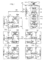
- Fig. 1 is a block diagram showing a network I/O system in a first embodiment of the invention.
- the network I/O system in the invention is configured by a central communication unit 110 connected with a host computer 100 and terminal communication units 120a, 120b, 120c, 120d and 120e.
- the central communication unit 110 provides a host computer interface unit 160, a digital I/O data storing unit 140, an identification number setting data storing unit 141, a communication port 150, and a central communication control unit 130.
- the identification number setting data storing unit 141 also has an identification number storing unit 141a for storing the identification number to be set in the terminal communication units 120a, 120b, 120c, 120d and 120e, and a routing data storing unit 141b for storing routing data for each of the terminal communication units 120a, 120b, 120c, 120d and 120e regarding from the central communication unit 110 to the terminal communication units 120a, 120b, 120c, 120d and 120e.
- the each of the terminal communication units 120a, 120b, 120c, 120d and 120e provides an upstream communication port 151, a plurality of downstream communication ports 152a and 152b, a digital I/O port 161, a terminal communication control unit 131, and an identification number designating unit 144.
- the upstream communication port 151 in the terminal communication units 120a, 120b, 120c, 120d and 120e is connected with a communication port 150 in the central communication unit 110 and also connected with the upstream communication port 152a and the downstream communication port 152b via the terminal communication control unit 131.
- Reference numerals indicated in the terminal communication unit 120a are appended to the terminal communication units 120b, 120c, 120d and 120e as the same elements.
- the digital I/O port 161 in the terminal communication units 120a, 120b, 120c, 120d and 120e is connected with controlled devices, for example, a sensor, an actuator, etc.
- the host computer 100 sends, to the central communication unit 110, the routing data generated in accordance with a generating method in advance, as an after-mentioned description, regarding from the central communication unit 110 to all of the terminal communication units 120a, 120b, 120c, 120d and 120e, and the identification number to be set in all of the terminal communication units 120a, 120b, 120c, 120d and 120e.
- the routing data and identification number are stored in the identification number setting data storing unit 141 via a host computer interface unit 160.
- the host computer 100 stores an output value from the digital I/O port 161 in all of the terminal communication units 120a, 120b, 120c, 120d and 120e in the digital I/O data storing unit 140 in the central communication unit 110 via the host computer interface unit 160.
- Digital input values, stored in the digital I/O data storing unit 140 in the central communication unit 110 via the host computer interface unit 160, are checked to thereby confirm the digital input values regarding all of the terminal communication units 120a, 120b, 120c, 120d and 120e.
- the central communication unit 110 also provides a terminal type data storing unit 143, and the each of the terminal communication units 120a, 120b, 120c, 120d and 120e provides a terminal type number designating unit 145.
- the central communication unit 110 transmits and receives data to/from the host computer 100 via the host computer interface unit 160 to transmit and receive the data to/from the terminal communication units 120a, 120b, 120c, 120d and 120e via the communication port 150 controlled by the central communication control unit 130.
- the central communication control unit 130 outputs, to the communication port 150, data as an identification number setting packet combined with the routing data and the identification number at every terminal communication unit 120a, 120b, 120c, 120d or 120e, when the routing data and identification number of the respective terminal communication units 120a, 120b, 120c, 120d and 120e are set in the identification number setting data storing unit 141 by the host computer 100. Thereafter, the central communication control unit 130 repeatedly outputs the identification number setting packet of all of the terminal communication units 120a, 120b, 120c, 120d and 120e to the communication port 150.
- the central communication control unit 130 then receives an identification number setting completion packet indicating a setting completion of the identification number transmitted from the terminal communication unit 120a, 120b, 120c, 120d or 120e to then halt the transmission of the identification number setting data of the sending source among the terminal communication units 120a, 120b, 120c, 120d and 120e.
- the central communication control unit 130 When a digital output value is set in the digital I/O data storing unit 140, the central communication control unit 130 also outputs, to the communication port 150, data as a digital output packet combined with the identification number in the terminal communication unit 120a, 120b, 120c, 120d or 120e corresponding to the digital output value, which was set, and this digital output value. Further, the central communication control unit 130 receives a digital input packet combined with the identification number of the terminal communication unit 120a, 120b, 120c, 120d or 120e and the digital input value from the communication port 150 to then store the data of digital input packet in the digital I/O data storing unit 140.
- the communication port 150 transmits the packet, received from the central communication control unit 130, to the upstream communication port 151 in terminal communication unit 120a to be connected and outputs the packet, received from the upstream communication port 151 in terminal communication unit 120a, to the central communication control unit 130.
- the each of the terminal communication units 120a, 120b, 120c, 120d and 120e has the terminal communication control unit 131 which transmits and receives data to/from the controlled devices via the digital I/O port 161, data to/from the central communication unit 110 via the upstream communication port 151 or the other terminal communication unit 120a, 120b, 120c, 120d or 120e, and data to/from the other terminal communication unit 120a, 120b, 120c, 120d or 120e via the downstream communication port 152a or 152b.
- the terminal communication control unit 131 When the terminal communication control unit 131 receives the identification number setting packet from the upstream communication port 151, it sets a value as an identification number to be stored in an identification number portion of the identification number setting packet if the least significant number of the data in the routing data portion among the identification number setting packets is "1" indicating that the identification number is set in the corresponding terminal communication unit 120a, 120b, 120c, 120d or 120e. Further, if the least significant number of the data in the routing data portion is "2" indicating the downstream communication port 152a, the terminal communication control unit 131 deletes the value of the least significant number to transmit the remaining data of the routing data portion to the downstream communication port 152a. If the least significant number is "3" indicating the downstream communication port 152b, the terminal communication unit 131 deletes the value of the least significant number to transmit the remaining data thereof to the downstream communication port 152b.
- a digital output value of the digital output packet is set in the digital I/O port 161 if the identification number data of the digital output packet is matched with the identification number of the corresponding terminal communication unit 120a, 120b, 120c, 120d or 120e. If it is not matched with the identification number thereof, the terminal communication control unit 131 transmits the digital output packet to the downstream communication ports 152a and 152b.
- the terminal communication control unit 131 transmits the digital input packet combined the digital input value with an own identification number to the upstream communication port 151 when the digital input value is varied.
- the terminal communication control unit 131 outputs the packet to the upstream communication port 151 when receiving the packet from the downstream communication port 152a or 152b.
- Fig. 2 shows a packet format to be used for a data communication.
- the packet format is configured by a data portion 200 corresponding to transmission/reception data, a packet type portion 201 indicating a type of the packet, and an identification number portion 202 indicating the identification number of the terminal communication unit 120a, 120b, 120c, 120d or 120e.
- the data portion 200 stores either I/O data of the digital I/O port 161 in the terminal communication unit 120a, 120b, 120c, 120d or 120e, or the routing data of the identification number setting data.
- the packet type portion 201 stores "10" when the packet type is the digital input packet, stores "11” when the packet type is the digital output packet, stores "20” when the packet type is the identification number setting packet, stores "30” when the packet type is the identification number setting completion packet, and stores "40” when the packet type is a terminal type number packet.
- the central communication control unit 130 and terminal communication control unit 131 refer to the packet type portion 201 to determine the type of packet and perform a process for the pieces of data.
- the identification number portion 202 stores the identification number to be set in the terminal communication unit 120a, 120b, 120c, 120d or 120e as a sending destination, that is, the identification number of the sending destination terminal communication unit 120a, 120b, 120c, 120d or 120e when the packet is transmitted to the terminal communication unit 120a, 120b, 120c, 120d or 120e from the central communication unit 110.
- the identification number portion 202 stores the identification number set in the own terminal communication unit 120a, 120b, 120c, 120d or 120e, that is, the identification number of a sending source terminal communication unit 120a, 120b, 120c, 120d or 120e when the packet is transmitted to the central communication unit 110 from the terminal communication unit 120a, 120b, 120c, 120d or 120e.
- the routing data is a sequentially arranged number of the downstream communication ports 152a, 152b in the terminal communication unit 120a, 120b, 120c, 120d or 120e through which the packet passes from the central communication unit 110 as far as the terminal communication unit 120a, 120b, 120c, 120d or 120e.
- the terminal communication unit 120a is represented by a number "2" indicating the communication port 150 in the central communication unit 110 and a number "1" indicating a targeted terminal communication unit since the unit 120a in Fig. 1 is connected with the communication port 150 in the central communication unit 110. That is, the routing data becomes "1 - 2".
- the terminal communication unit 120b is represented by a number "2" indicating the communication port 150 in the central communication unit 110, a number “2” indicating the downstream communication port 152a in the terminal communication unit 120b, and a number “1” indicating a targeted terminal communication unit 120b since the terminal communication unit 120b is connected with the downstream communication port 152b in the terminal communication unit 120a. That is, the routing data becomes "1 - 2 - 2".
- Fig. 4A shows an example of a display screen on a display regarding an identification number setting application 400 using GUI (Graphical User Interface) used for generating the identification number setting data in the host computer 100.
- GUI Graphical User Interface
- the display screen of the identification number setting application 400 is configured by a network configuration setting portion 401, a terminal communication unit data displaying portion 402, a process displaying portion 403 for displaying a processing condition of the host computer 100, and an identification number setting data generating button 430.
- the network configuration setting portion 401 is configured by a terminal communication unit symbol 411 providing a central communication unit symbol 410, an upstream communication port symbol 414, and downstream communication port symbols 415a, 415b, and a connection condition symbol 412.
- the upstream communication port symbol 414 in the terminal communication unit symbol 411 is connected with a communication port symbol 413 in the central communication unit symbol 410 by an operation of the system user, and the upstream communication port symbol 414 is connected with either the downstream communication port symbol 415a or 415b in another terminal communication unit symbol 411 by the connection condition symbol 412, so that a network configuration can be generated on a software.
- the respective terminal communication unit symbols 411 have a function for setting the identification number in the software, and a designated identification number is displayed on the own symbol.
- the terminal communication unit data displaying portion 402 is configured by an identification number displaying portion 420 and a terminal type number displaying portion 421.
- the identification number is set in the respective communication units 120a, 120b, 120c, 120d and 120e to be able to communicate the host computer 100 with any of the terminal communication units 120a, 120b, 120c, 120d and 120e. Thereafter, a correspondence of the identification number and terminal type of the terminal communication unit 120a, 120b, 120c, 120d or 120e to be able to communicate therewith, is displayed.
- the identification number setting application 400 generates a network configuration shown in Fig. 4A by the system user to generate the identification number setting data shown in Fig. 4B when depressing the identification number setting data generating button 430 and store in the identification number setting data storing unit 141 in the central communication unit 110 via the host computer interface unit 160.
- Fig. 5 is an explanatory diagram showing a processing procedure of an entire system when setting the identification number in the terminal communication units 120a, 120b and 120d, in this embodiment. The detailed processing procedure will be described on the basis of the identification number setting data as generated above in Fig. 4B .
- the host computer 100 generates the identification number setting data by the operation of identification number setting application 400 at a process 500.
- the generated identification number setting data (as a table) is stored in the identification number setting data storing unit 141 in the central communication unit 110 via the host computer interface unit 160 at a process 510.
- the central communication unit 110 generates an identification number setting packet for each of the terminal communication units 120a, 120b and 120d on the basis of the identification number setting data which was set, or three identification number setting packets at process 511.
- a value of the least significant number in the routing data is "2".
- the central communication unit 110 transmits the identification number setting data (first line in Fig. 4B ) to the terminal communication unit 120a, or a first identification number setting packet as indicated by the identification number "1" and the routing data "1 - 2" thereto.
- the central communication control unit 130 deletes the value of the least significant number from the routing data in the first identification number setting packet to then send the remaining of first identification number setting packet to the communication port 150 at a communication 550.
- the terminal communication unit 120a receives the first identification number setting packet via the upstream communication port 151.
- the routing data in the first identification number setting packet is "1", therefore, the value of the least significant number is "1".
- the identification number "1" is stored in the identification number designating unit 144 in the terminal communication unit 120a at a process 520.
- the terminal communication unit 120a transmits the identification number setting completion packet to the central communication unit 110 via the upstream communication port 151 at a communication 590.
- the central communication unit 110 stores the identification number setting completion data in the identification number setting completion data storing unit 142 at every time of receiving the identification number setting completion packet to then halt the transmission of identification number setting data of the terminal communication unit 120a, 120b or 120d as the sending source of the received identification number setting completion packet.
- the central communication unit 110 transmits the identification number setting data (second line in Fig. 4B ) to the terminal communication unit 120b, or a second identification number setting packet as indicated by the identification number "2" and the routing data "1 - 2 - 2" thereto.
- the central communication control unit 130 deletes the value of the least significant number from the routing data in the second identification number setting packet to then send the remaining of second identification number setting packet to the communication port 150 at a communication 560.
- the terminal communication unit 120a receives the second identification number setting packet via the upstream communication port 151.
- the routing data in the second identification number setting packet is "1 - 2", therefore, the value of the least significant number is "2".
- the terminal communication unit 120a deletes the value of the least significant number to send the remaining of second identification number setting packet to the downstream communication port 152a at a communication 561.
- the terminal communication unit 120b receives the second identification number setting packet via the upstream communication port 151.
- the routing data in the second identification number setting packet is "1", therefore, the value of the least significant number is "1".
- the identification number "2" is stored in the identification number designating unit 144 in the terminal communication unit 120b at a process 530.
- the terminal communication unit 120b transmits the identification number setting completion packet to the central communication unit 110 via the upstream communication port 151 at a communication 591.
- the central communication unit 110 transmits the identification number setting data (third line in Fig. 4B ) to the terminal communication unit 120d, or a third identification number setting packet as indicated by the identification number "2" and the routing data "1 - 3 - 2 - 2" thereto.
- the central communication control unit 130 deletes the value of the least significant number from the routing data in the third identification number setting packet to then send the remaining of third identification number setting packet to the communication port 150 at a communication 570.
- the terminal communication unit 120a receives the third identification number setting packet via the upstream communication port 151.
- the routing data in the third identification number setting packet is "1 - 3 - 2", therefore, the value of the least significant number is "2".
- the terminal communication 120a deletes the value of the least significant number from the routing data to then send the remaining of third identification number setting packet to the downstream communication port 152a at a communication 571.
- the terminal communication unit 120b receives the third identification number setting packet via the upstream communication port 151.
- the routing data in the third identification number setting packet is "1 - 3", therefore, the value of the least significant number is "3".
- the terminal communication unit 120b deletes the value of the least significant number from the routing data to send the remaining of third identification number setting packet to the downstream communication port 152b at a communication 572.
- the terminal communication unit 120d cannot receive the third identification number setting packet since it is not connected with the network at a communication 572a.
- the host computer 100 refers to the identification number setting completion data storing unit 142 via the host computer interface unit 160 at a process 512 to start a communication between the terminal communication units 120a and 120b by using the setting completed identification numbers "1" and "2" at a process 501.
- the central communication unit 110 transfers cyclically and repeatedly the third identification number setting packet corresponding to an unsetting identification number "3" to the communication port 150 at a process 513, communication 570, communication 571 and communication 572a.
- the terminal communication unit 120d is connected with the network to receive the cyclically sent third identification number setting packet from the upstream communication port 151 at a communication 572b.
- the routing data in the third identification number setting packet is "1", therefore, the value of the least significant number is "1".
- the identification number "3" is stored in the identification number designating unit 144 in the terminal communication unit 120d at a process 540.
- the terminal communication unit 120d transmits the identification number setting completion packet to the central communication unit 110 via the upstream communication port 151 at a communication 592.
- the host computer 100 refers to the identification number setting completion data storing unit 142 via the host computer interface unit 160 to then start the communication among the terminal communication units 120a, 120b and 120d by using the setting completed identification numbers "1", "2" and "3", at a process 502.
- the identification number can be set in the plurality of terminal communication units 120a, 120b, 120c, 120d and 120e, and the data transmission and reception can be performed between the host computer 100 and the digital I/O port 161 in the plurality of terminal communication units 120a, 120b, 120c, 120d and 120e.
- the identification number can be set in all of the terminal communication units 120a, 120b, 120c, 120d and 120e on the basis of the routing data of the network, without using a unique address, switch, ROM, etc.
- the setting and change of the identification number for all of the terminal communication units 120a, 120b, 120c, 120d and 120e can be performed with centralization from the host computer 100.
- the central communication unit 110 provides the terminal type data storing unit 143 and each of the terminal communication units 120a, 120b, 120c, 120d and 120e provides the terminal type number designating unit 145, in this embodiment.
- the each of the terminal communication units 120a, 120b, 120c, 120d and 120e outputs, to the upstream communication port 151, the terminal type packet including the terminal type number and identification number to be stored in the terminal type number designating unit 145 when setting the identification number.
- the each of the terminal communication units 120a, 120b, 120c, 120d and 120e receives the terminal type packet from the downstream communication port 152a or 152b to output to the upstream communication port 151.
- the central communication unit 110 receives the terminal type packet from the communication port 151 to store the terminal type of all of the terminal communication units 120a, 120b, 120c, 120d and 120e in the terminal type data storing unit 143.
- the host computer 100 refers to the terminal type number, stored in the terminal type data storing unit 143 in the central communication unit 110, of the terminal communication units 120a, 120b, 120c, 120d and 120e to then confirm the terminal type of the terminal communication units 120a, 120b, 120c, 120d and 120e. According to the above-mentioned method in this embodiment, the host computer 100 can confirm the terminal type, a sort of which is expected by the terminal communication unit 120a, 120b, 120c, 120d or 120e connected with the network.
- a second embodiment of the invention will be described below.
- a system configuration of the second embodiment is the same as that of the first embodiment shown in Fig. 1 .
- the each of the terminal communication units 120a, 120b, 120c, 120d and 120e generates a routing recognition packet by the terminal communication control unit 131.
- the terminal communication control unit 131 in the terminal communication units 120a, 120b, 120c, 120d and 120e transmits the routing recognition packet to the central communication unit 110 via the upstream communication port 151 or to other terminal communication unit 120a, 120b, 120c, 120d or 120e, and also receives the routing recognition packet from the terminal communication unit 120a, 120b, 120c, 120d or 120e via the downstream communication port 152a or 152a in the terminal communication unit 120a, 120b, 120c, 120d or 120e.
- the terminal communication control unit 131 transmits the routing recognition packet, in which the data portion 200 ( Fig. 2 ) is "1", to the upstream communication port 151 when the upstream communication port 151 is connected with the network.
- the terminal communication control unit 131 appends a value "2", for example, indicating the downstream communication port 152a, to the ending of data portion 200 ( Fig. 2 ) of the routing recognition packet to transmit to the upstream communication port 151 if the routing recognition packet is entered from the downstream communication port 152a.
- the terminal communication control unit 131 appends a value "3", for example, indicating the downstream port 152b, to the ending of data portion 200 thereof to transmit to the upstream communication port 151 if the routing recognition packet is entered from the downstream communication port 152b.
- the central communication control unit 130 appends a value "2", for example, indicating the communication port 150, to the ending of data portion 200 in the routing recognition packet received from the communication port 150 to store in the routing data storing unit 141b in the identification number setting data storing unit 141.
- the host computer 100 refers to the routing recognition data stored in the routing data storing unit 141b in the identification number setting data storing unit 141 via the host computer interface unit 160 to thereby recognize the routing data as far as the terminal communication units 120a, 120b, 120c, 120d and 120e.
- Fig. 6 is an explanatory diagram showing data stored in the routing data storing unit 141b.
- the routing recognition data is transmitted as the routing recognition packet from the terminal communication units 120a, 120b, 120c, 120d and 120e to be appended, in the order, with the port numbers of either downstream communication port 152a or 152b of the terminal communication unit 120a, 120b, 120c, 120d or 120e through which the routing recognition data is passed as far as the central communication unit 110. In this way, the routing data is generated.
- the routing recognition packet transmitted from the terminal communication unit 120a has a value "1" in an initial condition.
- the central communication control unit 130 appends a value "2" indicating the communication port 150 to the ending of data portion 200. That is, the routing recognition data becomes "1 - 2".
- the routing recognition packet transmitted from the terminal communication unit 120b has a value "1" in the initial condition.
- the terminal communication control unit 131 appends a value "2" indicating the downstream communication port 152a to the ending of data portion 200 to then transmit to the upstream communication port 151.
- the central communication control unit 130 appends a value "2" indicating the communication port 150 to the ending of data portion 200. That is, the routing recognition data becomes "1 - 2 - 2".
- the central communication unit 110 receives the routing recognition data from all of the terminal communication units 120a, 120b, 120c, 120d and 120e to then store in the routing data storing unit 141b as shown in Fig. 6 . Therefore, the host computer 100 refers to the routing data storing unit 141b via the host computer interface unit 160 to be able to recognize all of the routing data as far as the terminal communication units 120a, 120b, 120c, 120d and 120e.
- each of the terminal communication units 120a, 120b, 120c, 120d and 120e appends a terminal type number to be stored in the terminal type number designating unit 145 to the identification number portion 202 ( Fig. 2 ) in the routing recognition packet to then be transmitted. Therefore, the central communication unit 110 performs simultaneously storing the routing recognition data in accordance with the above-mentioned operation and storing the terminal type number in the terminal type data storing unit 143, so that the host computer 100 can simultaneously recognize the routing data and terminal type number of the terminal communication units 120a, 120b, 120c, 120d and 120e.
- Fig. 7 is a diagram showing an example of a display screen. This display screen is configured such that the host computer 100 recognizes a configuration of the entire network on the basis of the routing data and terminal type number recognized by the above-mentioned method to represent a network configuration by the GUI.
- the display screen of a network configuration display setting application 700 is configured by a network configuration displaying portion 701, a terminal communication unit data displaying portion 402, a process displaying portion 403, an identification number setting data generating button 430, and an identification number automatic setting button 730.
- the network configuration displaying portion 701 is configured by the terminal communication unit symbol 411 providing the central communication unit symbol 410, the upstream communication port symbol 414 and the downstream communication port symbols 415a, 415b; a controlled device symbol 710 representing the controlled device connected with the terminal communication units 120a, 120b, 120c, 120d and 120e; and the connection condition symbol 412.
- the upstream communication port symbol 414 in the terminal communication unit symbol 411 is connected with either the communication port symbol 413 in the central communication unit symbol 410 or the downstream communication port 415a, 415b in another terminal communication unit symbol 411 by the connection condition symbol 412.
- the network configuration displaying portion 701 has a function for automatically displaying the network configuration recognized by the host computer 100.
- Each of the terminal communication unit symbols 411 has a function for setting the identification number in the software, and a designated identification number is displayed on itself.
- the terminal communication unit data displaying portion 402 is configured by the identification number displaying portion 420 and the terminal type number displaying portion 421.
- the identification number is set in the terminal communication units 120a, 120b, 120c, 120d and 120e to be able to communication the host computer 100 with any of the terminal communication units 120a, 120b, 120c, 120d and 120e. Thereafter, a correspondence of the identification number and terminal type of the terminal communication unit 120a, 120b, 120c, 120d or 120e is displayed.
- the identification number setting data generating button 430 is depressed by the system user, after setting the identification number in the terminal communication unit symbol 411 of the network configuration displayed on the network configuration displaying portion 701, to thereby generate the identification number setting table and store in the host computer 100.
- the identification number automatic setting button 730 is depressed by the system user, after the network configuration is displayed on the network configuration displaying portion 701 to automatically set the identification number in the terminal communication unit symbol 410 by a process of the software.
- the routing between the network configuration and the controlled device is recognized dynamically to be displayed on the network configuration display setting application 700 in the host computer 100, so that a confirmation work of the system configuration can be made easily for the system user.
- a man-caused mistake such as a connection mistake between the terminal communication units 120a, 120b, 120c, 120d, 120e and the controlled device, which occurs at a time of configuring, adding and changing the system, can be reduced.
- the network I/O system in the invention will be described with a case where it is applied to a chip mounter as a field of industrial machinery.
- the chip mounter is used for manufacturing printed-wiring boards, and electronic parts are arranged and mounted on the printed-wiring board to make a printed circuit board.
- a device of type so-called modular mounter provides a dedicated parts supply work unit gathered together with a number of parts supply devices and a plurality of part mounting head work units.
- This modular mounter controls the entire chip mounters by controlling data I/O of the plurality of controlled devices in the respective work units.
- the modular mounter changes detachably the respective work units to the chip mounter itself depending on the type of electronic parts, the printed circuit board, etc.
- the central communication unit 110 may be mounted on the host computer 100 used for control, and the plurality of terminal communication units 120a, 120b, 120c, 120d and 120e may also be mounted on a modular unit or the work unit.
Landscapes
- Engineering & Computer Science (AREA)
- Computer Networks & Wireless Communication (AREA)
- Signal Processing (AREA)
- Small-Scale Networks (AREA)
- Data Exchanges In Wide-Area Networks (AREA)
Abstract
Description
- The present invention relates to a network I/O system and a network configuring method in which signals at digital I/O ports corresponding to a multipoint for digitally controlling a plurality of controlled devices are multiplexed to reduce the number of wirings in an industrial machinery etc.
- The network I/O system provides a host computer, a central communication unit connected with the host computer, and a plurality of terminal communication units each having digital I/O ports. The central communication unit and the plurality of terminal communication units configure a network configuration by using a multi-drop connection, a daisy-chain connection, etc.
- In the past, the input/output of data between the host computer and the plurality of controlled devices such as sensors, actuators, etc. which are disposed dispersedly, has performed by connecting the controlled devices directly to the host computer, therefore, a number of wirings are required.
- The network I/O system configures a network in which the host computer is connected with the plurality of dispersedly disposed controlled devices, and the signals at digital I/O ports are multiplexed to realize the data input/output between the host computer and the plurality of controlled devices by a simple connection of using a small number of wirings. This has been used mainly in the industrial field in which a number of the controlled devices are easily dispersed in such as industrial machineries for manufacturing automobiles, machine tools, chip mounters, etc.
- Here, it is required to set an identification number, in the terminal communication unit, for designating a sending destination and a sending source of a communication so that the communication is performed between the host computer and the terminal communication units each connected with the controlled device.
- In the past, a setting of the identification number in the terminal communication units has been performed by the following method. That is, a switch and ROM (Read-only Memory) are provided on the respective terminal communication units and non-overlapped values are assigned respectively to the terminal communication units by using the switch and ROM in manual when incorporating the network I/O system in a machine.
- Here, when changing or adding a network configuration, the system must be built up correctly by not only resetting the identification number for each of the above-mentioned terminal communication units but also figuring out accurately, by a system user, a type of the controlled device connected with the respective terminal communication units and the network configuration as well as the identification number set in the terminal communication units. In the past, the following procedure has been performed in manual: confirmation of the network configuration configured by the respective terminal communication units and the type of controlled device connected with the terminal communication units; and confirmation of the identification number set in the respective terminal communication units.
- For a purpose of solving the above-mentioned problem,
JP-A-2005-260828 - One problem to be solved by the invention is that the identification number for the respective terminal communication units is directly set in manual by using the unique address, switch, ROM, etc.
- The other problem to be solved by the invention is that the related art cannot dynamically recognize the identification number appended to the respective terminal communication units in the network I/O system and a connection configuration of the network, and the type of controlled devices connected with the terminal communication units.
- In response to the above-mentioned problems, one object of the invention is to provide a dynamically and flexibly configuring method of the identification number for the terminal communication units on the basis of a network routing, without setting directly in manual by using the assignment of unique address, switch, ROM, etc.
- The other object of the invention is to provide a dynamically recognizable system for the identification number set in the terminal communication units and the connection configuration in the network I/O system, and the type of controlled devices connected with the respective terminal communication units.
- The above objects are achieved by a network I/O system, a central communication unit, a terminal communication unit and a network configuration method according to the independent claims respectively.
- According to a first aspect of the invention, the invention provides a network I/O system comprising: a host computer; a central communication unit including a host computer interface unit, a digital I/O data storing unit, an identification number setting data storing unit, an identification number setting completion data storing unit, at least one communication port, and a central communication control unit; and a plurality of terminal communication units each including an upstream communication port, a plurality of downstream communication ports, and a terminal communication control unit, wherein the upstream communication port in a first of the terminal communication units is connected with the communication port in the central communication unit, at least one of the downstream communication ports in the first of the terminal communication units is connected with another upstream communication port in a second of the terminal communication units, and the at least one of the downstream communication ports in the second of the terminal communication units is connected with another upstream communication port in a third of the terminal communication control units,
the network I/O system comprising: that in a routing through which the central communication unit is connected to the terminal communication units via the downstream communication ports in other terminal communication units, the identification number setting data storing unit in the central communication unit stores identification number setting data combined, routing data combined a port number of the downstream communication ports in the terminal communication units passed in sequence from the central communication unit on the routing by a number of the other terminal communication units connected between the central communication unit and the terminal communication unit, with the identification numbers as non-overlapped and individually set in the terminal communication units; and the terminal communication unit includes an identification number designating unit for storing the identification number in the identification number setting data received from the upstream communication port. - The identification number setting data storing unit in the central communication unit includes an identification number storing unit for storing the identification number to be set in the terminal communication unit, and a routing data storing unit for storing the routing data for every terminal communication unit from the central communication unit to the respective terminal communication units.
- The terminal communication unit includes a terminal type number designating unit for storing a terminal type number uniquely determined for every type of controlled devices connected with the digital I/O port.
- The central communication unit includes a terminal type data storing unit for storing the terminal type number transmitted from the terminal communication unit.
- According to a second aspect of the invention, the invention provides a central communication unit for use in a network I/O system, connected with a host computer and a plurality of terminal communication units, wherein an upstream communication port in a first of the terminal communication units is connected with a communication port in the central communication unit, at least one of downstream communication ports in the first of the terminal communication units is connected with another upstream communication port in a second of the terminal communication units, and the at least one of the downstream communication ports in the second of the terminal communication units is connected with another upstream communication port in a third of the terminal communication control units, in a routing through which the central communication unit is connected to the terminal communication units via the downstream communication ports in other terminal communication units, an identification number setting data storing unit in the central communication unit stores identification number setting data combined, routing data combined a port number of the downstream communication ports in the terminal communication units passed in sequence from the central communication unit on the routing by a number of the other terminal communication units connected between the central communication unit and the terminal communication unit, with the identification numbers as non-overlapped and individually set in the terminal communication units; and the terminal communication unit includes an identification number designating unit for storing the identification number in the identification number setting data received from the upstream communication port,
the central communication unit comprising: a host computer interface unit; a digital I/O data storing unit; an identification number setting data storing unit; an identification number setting completion data storing unit; at least one communication port; and a central communication control unit, wherein the identification number setting data storing unit includes an identification number storing unit and a routing data storing unit. - According to a third aspect of the invention, the invention provides a terminal communication unit for use in a network I/O system providing a central communication unit connected with a host computer and a plurality of terminal communication units, wherein an upstream communication port in a first of the terminal communication units is connected with a communication port in the central communication unit, at least one of downstream communication ports in the first of the terminal communication units is connected with another upstream communication port in a second of the terminal communication units, and the at least one of the downstream communication ports in the second of the terminal communication units is connected with another upstream communication port in a third of the terminal communication control units, in a routing through which the central communication unit is connected to the terminal communication units via the downstream communication ports in other terminal communication units, an identification number setting data storing unit in the central communication unit stores identification number setting data combined, routing data combined a port number of the downstream communication ports in the terminal communication units passed in sequence from the central communication unit on the routing by a number of the other terminal communication units connected between the central communication unit and the terminal communication unit, with the identification numbers as non-overlapped and individually set in the terminal communication units; and the terminal communication unit includes an identification number designating unit for storing the identification number in the identification number setting data received from the upstream communication port,
the terminal communication unit comprising: the upstream communication port; the plurality of downstream communication ports; a terminal communication control unit; and the identification number designating unit. - The network I/O system further comprises a controller incorporating the central communication unit and a work unit incorporating the terminal communication unit and detachable from a device body.
- According to a fourth aspect of the invention, the invention provides a network configuration method performed by: a host computer; a central communication unit including a host computer interface unit, a digital I/O data storing unit, an identification number setting data storing unit, an identification number setting completion data storing unit, at least one communication port, and a central communication control unit; and a plurality of terminal communication units each including at least one upstream communication port, a plurality of downstream communication ports, at least one digital I/O port, a terminal communication control unit, and an identification number designating unit, wherein the upstream communication port in a first of the terminal communication units is connected with the communication port in the central communication unit, at least one of the downstream communication ports in the first of the terminal communication units is connected with another upstream communication port in a second of the terminal communication units, and the at least one of the downstream communication ports in the second of the terminal communication units is connected with another upstream communication port in a third of the terminal communication control units,
the network configuration method comprising the steps: that in a routing through which the central communication unit is connected to the terminal communication units via the downstream communication ports in other terminal communication units, the host computer stores identification number setting data combined, routing data combined a port number of the downstream communication ports in the terminal communication units passed in sequence from the central communication unit on the routing by a number of the other terminal communication units connected between the central communication unit and the terminal communication unit, with the identification numbers as non-overlapped and individually set in the terminal communication units, in the identification number setting data storing unit in the central communication unit for every terminal communication unit connected with a network; the central communication unit transmits the identification number setting data stored in the identification number setting data storing unit by a number of the terminal communication units connected with the network, to the upstream communication port in the terminal communication unit connected with the central communication unit via a communication port; the terminal communication unit refers to a value of a least significant number in the routing data in the identification number setting data received from the upstream communication port to delete the value of the least significant number if the value is the port number of the downstream communication port, transmit the identification number setting data to the downstream communication port corresponding to the port number, store the identification number in the identification number setting data in the identification number designating unit if the value is not the port number corresponding to the downstream communication port, and output identification number setting completion data indicating that the identification number is set simultaneously in the upstream communication port; and the central communication unit halts transmitting the identification number setting data of the terminal communication unit to be a sending source when receiving the identification number setting completion data. - The terminal communication unit includes a terminal type number designating unit for storing a terminal type number uniquely determined for every type of controlled devices connected with the digital I/O port; the terminal communication unit combines the terminal type number stored in the terminal type number designating unit with the terminal number stored in the identification number designating unit to transmit to the upstream communication port and transmit the received terminal type number and terminal number to the upstream communication port without change if the combined the terminal type number with the terminal number is received from the downstream communication port; the central communication unit stores apart the terminal type number of all of the terminal communication units for every identification number in the terminal type data storing unit in accordance with the received terminal type number and identification number from the communication port; and the host computer recognizes a type of the controlled devices connected with the respective terminal communication units in accordance with the terminal type number stored in the terminal type data storing unit in the central communication unit.
- According to a fifth aspect of the invention, the invention provides a network configuration method performed by: a host computer; a central communication unit including a host computer interface unit, a digital I/O data storing unit, an identification number setting data storing unit, an identification number setting completion data storing unit, at least one communication port, and a central communication control unit; and a plurality of terminal communication units each including at lease one upstream communication port, a plurality of downstream communication ports, at least one digital I/O port, a terminal communication control unit, and an identification number designating unit, wherein the upstream communication port in a first of the terminal communication units is connected with the communication port in the central communication unit, the at least one of downstream communication ports in the first of the terminal communication units is connected with another upstream communication port in a second of the terminal communication units, and the at least one of the downstream communication ports in the second of the terminal communication units is connected with another upstream communication port in a third of the terminal communication control units,
the network configuration method comprising the steps: that the terminal communication unit transmits routing recognition data to the upstream communication port when connecting to a network, and when receiving the routing recognition data from the downstream communication port, a communication port number of the received downstream communication port is appended to the routing recognition data to transmit to the upstream communication port; the central communication unit stores the routing recognition data, received from the communication port, of all of the terminal communication units in the routing data storing unit; and the host computer recognizes the routing data from the central communication unit to the respective terminal communication units in accordance with the routing recognition data, stored in the central communication unit, of the respective terminal communication units. - The terminal communication unit includes a terminal type number designating unit for storing a terminal type number uniquely determined for every type of controlled devices connected with the digital I/O port, transmits a combination of combining the routing recognition data with the terminal type number stored in the terminal type number designating unit to the upstream communication port when the terminal communication unit itself is connected with the network, transmits a combination of combining the communication port number of the received downstream communication port with the received routing recognition data to the upstream communication port when receiving the combination of combining the routing recognition data with the terminal type number from the downstream communication port, and the central communication unit stores the routing recognition data of all of the terminal communication units in the routing data storing unit in accordance with the routing recognition data and the terminal type number received from the communication port and stores the terminal type numbers of all of the terminal communication units in the terminal type data storing unit; and the host computer recognizes the routing data from the central communication unit to the respective terminal communication units in accordance with the routing recognition data, stored in the central communication unit, of the respective terminal communication units, and recognizes a type of the controlled devices connected respectively with the terminal communication units in accordance with the terminal type number stored in the central communication unit.
- According to the invention, the assignment of unique address and the configuration of the switch, ROM, etc. are not required by appending the identification data dynamically to the terminal communication units on the basis of the network routing, so that an advantage can be obtained such that the number of man-hour caused in manual is considerably reduced at a time of manufacturing the terminal communication unit, starting up the system, and changing the connection configuration of the network.
- Further, according to the invention, the configuration of network system can be recognized dynamically by the network connection configuration and the type of controlled device connected with the terminal communication units, so that the addition and change for the system can be performed easily by presenting the recognized configuration of network system to the user, and an advantage can be obtained such that a man-caused mistake is easily acknowledged in the system configuration.
- The other objects, features and advantages of the invention will become apparent from the following description of the embodiments of the invention taken in conjunction with the accompanying drawings.
-
-
Fig. 1 is a block diagram showing a basic configuration of a network I/O system in the invention; -
Fig. 2 is an explanatory diagram showing packet format data used for a network communication in the invention; -
Fig. 3 is an explanatory diagram showing routing data stored in a routing data storing unit in a first embodiment of the invention; -
Fig. 4A is an explanatory diagram for a screen display and function of an identification number setting application in the first embodiment; -
Fig. 4B is an explanatory diagram for the routing data and identification number in the first embodiment; -
Fig. 5 is an explanatory diagram for a setting procedure of an identification number inFig. 4B ; -
Fig. 6 is an explanatory diagram for routing recognition data to be stored in the routing data storing unit in a second embodiment of the invention; and -
Fig. 7 is an explanatory diagram for a screen display and function of the identification number setting application in the second embodiment. - Hereinafter, embodiments of the invention will be described with reference to the drawings.
-
Fig. 1 is a block diagram showing a network I/O system in a first embodiment of the invention. The network I/O system in the invention is configured by acentral communication unit 110 connected with ahost computer 100 andterminal communication units - The
central communication unit 110 provides a hostcomputer interface unit 160, a digital I/Odata storing unit 140, an identification number settingdata storing unit 141, acommunication port 150, and a centralcommunication control unit 130. The identification number settingdata storing unit 141 also has an identificationnumber storing unit 141a for storing the identification number to be set in theterminal communication units data storing unit 141b for storing routing data for each of theterminal communication units central communication unit 110 to theterminal communication units - The each of the
terminal communication units upstream communication port 151, a plurality ofdownstream communication ports O port 161, a terminalcommunication control unit 131, and an identificationnumber designating unit 144. - The
upstream communication port 151 in theterminal communication units communication port 150 in thecentral communication unit 110 and also connected with theupstream communication port 152a and thedownstream communication port 152b via the terminalcommunication control unit 131. Reference numerals indicated in theterminal communication unit 120a are appended to theterminal communication units - Further, the digital I/
O port 161 in theterminal communication units - Next, an operation of the
host computer 100 in this embodiment will be described below. Thehost computer 100 sends, to thecentral communication unit 110, the routing data generated in accordance with a generating method in advance, as an after-mentioned description, regarding from thecentral communication unit 110 to all of theterminal communication units terminal communication units data storing unit 141 via a hostcomputer interface unit 160. - Further, the
host computer 100 stores an output value from the digital I/O port 161 in all of theterminal communication units data storing unit 140 in thecentral communication unit 110 via the hostcomputer interface unit 160. Digital input values, stored in the digital I/Odata storing unit 140 in thecentral communication unit 110 via the hostcomputer interface unit 160, are checked to thereby confirm the digital input values regarding all of theterminal communication units - The
central communication unit 110 also provides a terminal typedata storing unit 143, and the each of theterminal communication units number designating unit 145. - Next, an operation of the
central communication unit 110 in this embodiment will be described below. Thecentral communication unit 110 transmits and receives data to/from thehost computer 100 via the hostcomputer interface unit 160 to transmit and receive the data to/from theterminal communication units communication port 150 controlled by the centralcommunication control unit 130. - The central
communication control unit 130 outputs, to thecommunication port 150, data as an identification number setting packet combined with the routing data and the identification number at everyterminal communication unit terminal communication units data storing unit 141 by thehost computer 100. Thereafter, the centralcommunication control unit 130 repeatedly outputs the identification number setting packet of all of theterminal communication units communication port 150. The centralcommunication control unit 130 then receives an identification number setting completion packet indicating a setting completion of the identification number transmitted from theterminal communication unit terminal communication units - When a digital output value is set in the digital I/O
data storing unit 140, the centralcommunication control unit 130 also outputs, to thecommunication port 150, data as a digital output packet combined with the identification number in theterminal communication unit communication control unit 130 receives a digital input packet combined with the identification number of theterminal communication unit communication port 150 to then store the data of digital input packet in the digital I/Odata storing unit 140. - The
communication port 150 transmits the packet, received from the centralcommunication control unit 130, to theupstream communication port 151 interminal communication unit 120a to be connected and outputs the packet, received from theupstream communication port 151 interminal communication unit 120a, to the centralcommunication control unit 130. - Next, an operation of the
terminal communication units terminal communication units communication control unit 131 which transmits and receives data to/from the controlled devices via the digital I/O port 161, data to/from thecentral communication unit 110 via theupstream communication port 151 or the otherterminal communication unit terminal communication unit downstream communication port - When the terminal
communication control unit 131 receives the identification number setting packet from theupstream communication port 151, it sets a value as an identification number to be stored in an identification number portion of the identification number setting packet if the least significant number of the data in the routing data portion among the identification number setting packets is "1" indicating that the identification number is set in the correspondingterminal communication unit downstream communication port 152a, the terminalcommunication control unit 131 deletes the value of the least significant number to transmit the remaining data of the routing data portion to thedownstream communication port 152a. If the least significant number is "3" indicating thedownstream communication port 152b, theterminal communication unit 131 deletes the value of the least significant number to transmit the remaining data thereof to thedownstream communication port 152b. - Further, when the terminal
communication control unit 131 receives a digital output packet from theupstream communication port 151, a digital output value of the digital output packet is set in the digital I/O port 161 if the identification number data of the digital output packet is matched with the identification number of the correspondingterminal communication unit communication control unit 131 transmits the digital output packet to thedownstream communication ports - The terminal
communication control unit 131 transmits the digital input packet combined the digital input value with an own identification number to theupstream communication port 151 when the digital input value is varied. - The terminal
communication control unit 131 outputs the packet to theupstream communication port 151 when receiving the packet from thedownstream communication port -
Fig. 2 shows a packet format to be used for a data communication. The packet format is configured by adata portion 200 corresponding to transmission/reception data, apacket type portion 201 indicating a type of the packet, and anidentification number portion 202 indicating the identification number of theterminal communication unit - The
data portion 200 stores either I/O data of the digital I/O port 161 in theterminal communication unit - The
packet type portion 201 stores "10" when the packet type is the digital input packet, stores "11" when the packet type is the digital output packet, stores "20" when the packet type is the identification number setting packet, stores "30" when the packet type is the identification number setting completion packet, and stores "40" when the packet type is a terminal type number packet. The centralcommunication control unit 130 and terminalcommunication control unit 131 refer to thepacket type portion 201 to determine the type of packet and perform a process for the pieces of data. - The
identification number portion 202 stores the identification number to be set in theterminal communication unit terminal communication unit terminal communication unit central communication unit 110. Theidentification number portion 202 stores the identification number set in the ownterminal communication unit terminal communication unit central communication unit 110 from theterminal communication unit - Here, a generating method of the routing data will be described with reference to
Fig. 3 . The routing data is a sequentially arranged number of thedownstream communication ports terminal communication unit central communication unit 110 as far as theterminal communication unit - For example, the
terminal communication unit 120a is represented by a number "2" indicating thecommunication port 150 in thecentral communication unit 110 and a number "1" indicating a targeted terminal communication unit since theunit 120a inFig. 1 is connected with thecommunication port 150 in thecentral communication unit 110. That is, the routing data becomes "1 - 2". - The
terminal communication unit 120b is represented by a number "2" indicating thecommunication port 150 in thecentral communication unit 110, a number "2" indicating thedownstream communication port 152a in theterminal communication unit 120b, and a number "1" indicating a targetedterminal communication unit 120b since theterminal communication unit 120b is connected with thedownstream communication port 152b in theterminal communication unit 120a. That is, the routing data becomes "1 - 2 - 2". - Next, the following description will be concerned with the setting of identification number in the
terminal communication units Fig. 1 as cited with an example. -
Fig. 4A shows an example of a display screen on a display regarding an identificationnumber setting application 400 using GUI (Graphical User Interface) used for generating the identification number setting data in thehost computer 100. - The display screen of the identification
number setting application 400 is configured by a networkconfiguration setting portion 401, a terminal communication unitdata displaying portion 402, aprocess displaying portion 403 for displaying a processing condition of thehost computer 100, and an identification number settingdata generating button 430. - Further, the network
configuration setting portion 401 is configured by a terminalcommunication unit symbol 411 providing a centralcommunication unit symbol 410, an upstreamcommunication port symbol 414, and downstreamcommunication port symbols connection condition symbol 412. The upstreamcommunication port symbol 414 in the terminalcommunication unit symbol 411 is connected with acommunication port symbol 413 in the centralcommunication unit symbol 410 by an operation of the system user, and the upstreamcommunication port symbol 414 is connected with either the downstreamcommunication port symbol communication unit symbol 411 by theconnection condition symbol 412, so that a network configuration can be generated on a software. - The respective terminal
communication unit symbols 411 have a function for setting the identification number in the software, and a designated identification number is displayed on the own symbol. - The terminal communication unit
data displaying portion 402 is configured by an identificationnumber displaying portion 420 and a terminal typenumber displaying portion 421. The identification number is set in therespective communication units host computer 100 with any of theterminal communication units terminal communication unit - Here, the identification
number setting application 400 generates a network configuration shown inFig. 4A by the system user to generate the identification number setting data shown inFig. 4B when depressing the identification number settingdata generating button 430 and store in the identification number settingdata storing unit 141 in thecentral communication unit 110 via the hostcomputer interface unit 160. -
Fig. 5 is an explanatory diagram showing a processing procedure of an entire system when setting the identification number in theterminal communication units Fig. 4B . - In the following example, it is assumed that the
terminal communication unit 120d is not connected with the network in the beginning. Thehost computer 100 generates the identification number setting data by the operation of identificationnumber setting application 400 at aprocess 500. The generated identification number setting data (as a table) is stored in the identification number settingdata storing unit 141 in thecentral communication unit 110 via the hostcomputer interface unit 160 at aprocess 510. - The
central communication unit 110 generates an identification number setting packet for each of theterminal communication units process 511. In this example, since thecentral communication unit 110 provides onecommunication port 150 alone, a value of the least significant number in the routing data is "2". - First, the
central communication unit 110 transmits the identification number setting data (first line inFig. 4B ) to theterminal communication unit 120a, or a first identification number setting packet as indicated by the identification number "1" and the routing data "1 - 2" thereto. The centralcommunication control unit 130 deletes the value of the least significant number from the routing data in the first identification number setting packet to then send the remaining of first identification number setting packet to thecommunication port 150 at acommunication 550. - The
terminal communication unit 120a receives the first identification number setting packet via theupstream communication port 151. In this case, the routing data in the first identification number setting packet is "1", therefore, the value of the least significant number is "1". To this end, the identification number "1" is stored in the identificationnumber designating unit 144 in theterminal communication unit 120a at aprocess 520. - The
terminal communication unit 120a transmits the identification number setting completion packet to thecentral communication unit 110 via theupstream communication port 151 at acommunication 590. Thecentral communication unit 110 stores the identification number setting completion data in the identification number setting completiondata storing unit 142 at every time of receiving the identification number setting completion packet to then halt the transmission of identification number setting data of theterminal communication unit - The
central communication unit 110 transmits the identification number setting data (second line inFig. 4B ) to theterminal communication unit 120b, or a second identification number setting packet as indicated by the identification number "2" and the routing data "1 - 2 - 2" thereto. The centralcommunication control unit 130 deletes the value of the least significant number from the routing data in the second identification number setting packet to then send the remaining of second identification number setting packet to thecommunication port 150 at acommunication 560. - The
terminal communication unit 120a receives the second identification number setting packet via theupstream communication port 151. In this case, the routing data in the second identification number setting packet is "1 - 2", therefore, the value of the least significant number is "2". To this end, theterminal communication unit 120a deletes the value of the least significant number to send the remaining of second identification number setting packet to thedownstream communication port 152a at acommunication 561. - The
terminal communication unit 120b receives the second identification number setting packet via theupstream communication port 151. In this case, the routing data in the second identification number setting packet is "1", therefore, the value of the least significant number is "1". To this end, the identification number "2" is stored in the identificationnumber designating unit 144 in theterminal communication unit 120b at aprocess 530. - The
terminal communication unit 120b transmits the identification number setting completion packet to thecentral communication unit 110 via theupstream communication port 151 at acommunication 591. - The
central communication unit 110 transmits the identification number setting data (third line inFig. 4B ) to theterminal communication unit 120d, or a third identification number setting packet as indicated by the identification number "2" and the routing data "1 - 3 - 2 - 2" thereto. The centralcommunication control unit 130 deletes the value of the least significant number from the routing data in the third identification number setting packet to then send the remaining of third identification number setting packet to thecommunication port 150 at acommunication 570. - The
terminal communication unit 120a receives the third identification number setting packet via theupstream communication port 151. In this case, the routing data in the third identification number setting packet is "1 - 3 - 2", therefore, the value of the least significant number is "2". To this end, theterminal communication 120a deletes the value of the least significant number from the routing data to then send the remaining of third identification number setting packet to thedownstream communication port 152a at acommunication 571. - The
terminal communication unit 120b receives the third identification number setting packet via theupstream communication port 151. In this case, the routing data in the third identification number setting packet is "1 - 3", therefore, the value of the least significant number is "3". To this end, theterminal communication unit 120b deletes the value of the least significant number from the routing data to send the remaining of third identification number setting packet to thedownstream communication port 152b at a communication 572. - The
terminal communication unit 120d cannot receive the third identification number setting packet since it is not connected with the network at acommunication 572a. - The
host computer 100 refers to the identification number setting completiondata storing unit 142 via the hostcomputer interface unit 160 at aprocess 512 to start a communication between theterminal communication units process 501. - The
central communication unit 110 transfers cyclically and repeatedly the third identification number setting packet corresponding to an unsetting identification number "3" to thecommunication port 150 at aprocess 513,communication 570,communication 571 andcommunication 572a. - The
terminal communication unit 120d is connected with the network to receive the cyclically sent third identification number setting packet from theupstream communication port 151 at acommunication 572b. In this case, the routing data in the third identification number setting packet is "1", therefore, the value of the least significant number is "1". To this end, the identification number "3" is stored in the identificationnumber designating unit 144 in theterminal communication unit 120d at aprocess 540. - The
terminal communication unit 120d transmits the identification number setting completion packet to thecentral communication unit 110 via theupstream communication port 151 at acommunication 592. - The
host computer 100 refers to the identification number setting completiondata storing unit 142 via the hostcomputer interface unit 160 to then start the communication among theterminal communication units process 502. - According to the above-mentioned operation, the identification number can be set in the plurality of
terminal communication units host computer 100 and the digital I/O port 161 in the plurality ofterminal communication units - According to the above-mentioned method in this embodiment, the identification number can be set in all of the
terminal communication units - Further, the setting and change of the identification number for all of the
terminal communication units host computer 100. - In this way, it is not required to assign the unique address on manufacturing the system. Further, it is not required to individually set and change the identification number by using the switch, ROM, etc when incorporating the network I/O system in a machine. Therefore, a competitive assignment of the identification numbers can be prevented from mistaking the setting of switch, ROM, etc.
- In the configuration shown in
Fig. 1 , thecentral communication unit 110 provides the terminal typedata storing unit 143 and each of theterminal communication units number designating unit 145, in this embodiment. The each of theterminal communication units upstream communication port 151, the terminal type packet including the terminal type number and identification number to be stored in the terminal typenumber designating unit 145 when setting the identification number. - The each of the
terminal communication units downstream communication port upstream communication port 151. Thecentral communication unit 110 receives the terminal type packet from thecommunication port 151 to store the terminal type of all of theterminal communication units data storing unit 143. - The
host computer 100 refers to the terminal type number, stored in the terminal typedata storing unit 143 in thecentral communication unit 110, of theterminal communication units terminal communication units host computer 100 can confirm the terminal type, a sort of which is expected by theterminal communication unit - A second embodiment of the invention will be described below. A system configuration of the second embodiment is the same as that of the first embodiment shown in
Fig. 1 . - An operation of the
terminal communication units terminal communication units communication control unit 131. The terminalcommunication control unit 131 in theterminal communication units central communication unit 110 via theupstream communication port 151 or to otherterminal communication unit terminal communication unit downstream communication port terminal communication unit - The terminal
communication control unit 131 transmits the routing recognition packet, in which the data portion 200 (Fig. 2 ) is "1", to theupstream communication port 151 when theupstream communication port 151 is connected with the network. In the case of entering the routing recognition packet into the terminalcommunication control unit 131 from either thedownstream communication port communication control unit 131 appends a value "2", for example, indicating thedownstream communication port 152a, to the ending of data portion 200 (Fig. 2 ) of the routing recognition packet to transmit to theupstream communication port 151 if the routing recognition packet is entered from thedownstream communication port 152a. In contrast, the terminalcommunication control unit 131 appends a value "3", for example, indicating thedownstream port 152b, to the ending ofdata portion 200 thereof to transmit to theupstream communication port 151 if the routing recognition packet is entered from thedownstream communication port 152b. - In the
central communication unit 110, the centralcommunication control unit 130 appends a value "2", for example, indicating thecommunication port 150, to the ending ofdata portion 200 in the routing recognition packet received from thecommunication port 150 to store in the routingdata storing unit 141b in the identification number settingdata storing unit 141. - The
host computer 100 refers to the routing recognition data stored in the routingdata storing unit 141b in the identification number settingdata storing unit 141 via the hostcomputer interface unit 160 to thereby recognize the routing data as far as theterminal communication units - Here, a generating method of the routing recognition data will be described below.
Fig. 6 is an explanatory diagram showing data stored in the routingdata storing unit 141b. The routing recognition data is transmitted as the routing recognition packet from theterminal communication units downstream communication port terminal communication unit central communication unit 110. In this way, the routing data is generated. - For example, since the
terminal communication unit 120a inFig. 1 is connected with thecommunication port 150 in thecentral communication unit 110, the routing recognition packet transmitted from theterminal communication unit 120a has a value "1" in an initial condition. When the routing recognition packet is entered into thecentral communication unit 110, the centralcommunication control unit 130 appends a value "2" indicating thecommunication port 150 to the ending ofdata portion 200. That is, the routing recognition data becomes "1 - 2". - Further, since the
terminal communication unit 120b is connected with thedownstream communication port 152b in theterminal communication unit 120a, the routing recognition packet transmitted from theterminal communication unit 120b has a value "1" in the initial condition. When the routing recognition packet is entered into theterminal communication unit 120a, the terminalcommunication control unit 131 appends a value "2" indicating thedownstream communication port 152a to the ending ofdata portion 200 to then transmit to theupstream communication port 151. When the routing recognition packet is entered into thecentral communication unit 110, the centralcommunication control unit 130 appends a value "2" indicating thecommunication port 150 to the ending ofdata portion 200. That is, the routing recognition data becomes "1 - 2 - 2". - The
central communication unit 110 receives the routing recognition data from all of theterminal communication units data storing unit 141b as shown inFig. 6 . Therefore, thehost computer 100 refers to the routingdata storing unit 141b via the hostcomputer interface unit 160 to be able to recognize all of the routing data as far as theterminal communication units - Further, the each of the
terminal communication units number designating unit 145 to the identification number portion 202 (Fig. 2 ) in the routing recognition packet to then be transmitted. Therefore, thecentral communication unit 110 performs simultaneously storing the routing recognition data in accordance with the above-mentioned operation and storing the terminal type number in the terminal typedata storing unit 143, so that thehost computer 100 can simultaneously recognize the routing data and terminal type number of theterminal communication units -
Fig. 7 is a diagram showing an example of a display screen. This display screen is configured such that thehost computer 100 recognizes a configuration of the entire network on the basis of the routing data and terminal type number recognized by the above-mentioned method to represent a network configuration by the GUI. - The display screen of a network configuration
display setting application 700 is configured by a networkconfiguration displaying portion 701, a terminal communication unitdata displaying portion 402, aprocess displaying portion 403, an identification number settingdata generating button 430, and an identification numberautomatic setting button 730. - The network
configuration displaying portion 701 is configured by the terminalcommunication unit symbol 411 providing the centralcommunication unit symbol 410, the upstreamcommunication port symbol 414 and the downstreamcommunication port symbols device symbol 710 representing the controlled device connected with theterminal communication units connection condition symbol 412. The upstreamcommunication port symbol 414 in the terminalcommunication unit symbol 411 is connected with either thecommunication port symbol 413 in the centralcommunication unit symbol 410 or thedownstream communication port communication unit symbol 411 by theconnection condition symbol 412. - In this way, the network
configuration displaying portion 701 has a function for automatically displaying the network configuration recognized by thehost computer 100. - Each of the terminal
communication unit symbols 411 has a function for setting the identification number in the software, and a designated identification number is displayed on itself. - The terminal communication unit
data displaying portion 402 is configured by the identificationnumber displaying portion 420 and the terminal typenumber displaying portion 421. The identification number is set in theterminal communication units host computer 100 with any of theterminal communication units terminal communication unit - The identification number setting
data generating button 430 is depressed by the system user, after setting the identification number in the terminalcommunication unit symbol 411 of the network configuration displayed on the networkconfiguration displaying portion 701, to thereby generate the identification number setting table and store in thehost computer 100. - The identification number
automatic setting button 730 is depressed by the system user, after the network configuration is displayed on the networkconfiguration displaying portion 701 to automatically set the identification number in the terminalcommunication unit symbol 410 by a process of the software. - According to the method in the second embodiment, the routing between the network configuration and the controlled device is recognized dynamically to be displayed on the network configuration
display setting application 700 in thehost computer 100, so that a confirmation work of the system configuration can be made easily for the system user. - In consequence, a man-caused mistake such as a connection mistake between the
terminal communication units - Further, it is possible to set the identification number of the
terminal communication units - Here, the network I/O system in the invention will be described with a case where it is applied to a chip mounter as a field of industrial machinery. The chip mounter is used for manufacturing printed-wiring boards, and electronic parts are arranged and mounted on the printed-wiring board to make a printed circuit board. Of the chip mounters, a device of type so-called modular mounter provides a dedicated parts supply work unit gathered together with a number of parts supply devices and a plurality of part mounting head work units. This modular mounter controls the entire chip mounters by controlling data I/O of the plurality of controlled devices in the respective work units. Further, the modular mounter changes detachably the respective work units to the chip mounter itself depending on the type of electronic parts, the printed circuit board, etc. to be used, and this modular mounter is changed from a configuration of the plural work units to a different configuration of the plural work units to be used. Therefore, in the control of chip mounter using the network I/O system, communication identification numbers which are not overlapped with each other, are appended respectively to the controlled devices in the respective work units. In this way, it is required to prevent a setting mistake of the identification number on manufacturing the work unit, and an overlapping and setting mistake of the identification number caused by a mounting error on detachably changing the work unit and a resetting the respective identification numbers. In the chip mounter, the
central communication unit 110 may be mounted on thehost computer 100 used for control, and the plurality ofterminal communication units - It should be further understood by those skilled in the art that although the foregoing description has been made on embodiments of the invention, the invention is not limited thereto and various changes and modifications may be made without departing from the spirit of the invention and the scope of the appended claims. The above embodiments of the invention as well as the appended claims and figures show multiple characterizing features of the invention in specific combinations. The skilled person will easily be able to consider further combinations or sub-combinations of these features in order to adapt the invention as defined in the in the claims to his specific needs.
Claims (13)
- A network I/O system comprising:a host computer (100);a central communication unit (110) including a host computer interface unit (160), a digital I/O data storing unit (140), an identification number setting data storing unit (141), an identification number setting completion data storing unit (142), at least one communication port (150), and a central communication control unit (130); anda plurality of terminal communication units (120a to 120e) each including an upstream communication port (151), a plurality of downstream communication ports (152a, 152b), and a terminal communication control unit (131),wherein the upstream communication port (151) in a first (120a) of the terminal communication units (120a to 120e) is connected with the communication port in the central communication unit (110), at least one of the downstream communication ports (152a, 152b) in the first of the terminal communication units is connected with another upstream communication port (151) in a second (120b) of the terminal communication units, and the at least one of the downstream communication ports (152a, 152b) in the second of the terminal communication units is connected with another upstream communication port (151) in a third (120c, 120d) of the terminal communication control units,the network I/O system comprising: thatin a routing through which the central communication unit is connected to the terminal communication units (120a to 120e) via the downstream communication ports in other terminal communication units, the identification number setting data storing unit (141) in the central communication unit stores identification number setting data combined, routing data combined a port number of the downstream communication ports in the terminal communication units passed in sequence from the central communication unit on the routing by a number of the other terminal communication units connected between the central communication unit and the terminal communication unit, with the identification numbers as non-overlapped and individually set in the terminal communication units; andthe terminal communication unit includes an identification number designating unit (144) for storing the identification number in the identification number setting data received from the upstream communication port (151).
- The system according to claim 1 wherein the identification number setting data storing unit (141) in the central communication unit includes an identification number storing unit (141a) for storing the identification number to be set in the terminal communication unit, and a routing data storing unit (141b) for storing the routing data for every terminal communication unit from the central communication unit (110) to the respective terminal communication units (120a to 120e).
- The system according to claim 1 wherein the terminal communication unit (120a to 120e) includes a terminal type number designating unit (145) for storing a terminal type number uniquely determined for every type of controlled devices connected with the digital I/O port (161).
- The system according to claim 1 wherein the central communication unit (110) includes a terminal type data storing unit (143) for storing the terminal type number transmitted from the terminal communication unit.
- A central communication unit (110) for use in a network I/O system, connected with a host computer (100) and a plurality of terminal communication units (120a to 120e),
wherein an upstream communication port (151) in a first (120a) of the terminal communication units (120a to 120e) is connected with a communication port (150) in the central communication unit, at least one of downstream communication ports (152a, 152b) in the first of the terminal communication units is connected with another upstream communication port (151) in a second (120b) of the terminal communication units, and the at least one of the downstream communication ports (152a, 152b) in the second of the terminal communication units is connected with another upstream communication port (151) in a third (120c, 120d) of the terminal communication control units,
in a routing through which the central communication unit is connected to the terminal communication units via the downstream communication ports in other terminal communication units, an identification number setting data storing unit (141) in the central communication unit stores identification number setting data combined, routing data combined a port number of the downstream communication ports in the terminal communication units passed in sequence from the central communication unit on the routing by a number of the other terminal communication units connected between the central communication unit and the terminal communication unit, with the identification numbers as non-overlapped and individually set in the terminal communication units; and
the terminal communication unit includes an identification number designating unit (144) for storing the identification number in the identification number setting data received from the upstream communication port (151),
the central communication unit comprising:a host computer interface unit (160); a digital I/O data storing unit (140); an identification number setting data storing unit (141); an identification number setting completion data storing unit (142); at least one communication port (150); and a central communication control unit (130),wherein the identification number setting data storing unit (141) includes an identification number storing unit (141a) and a routing data storing unit (141b). - A terminal communication unit (120a) for use in a network I/O system providing a central communication unit (110) connected with a host computer (100) and a plurality of terminal communication units (120b to 120e),
wherein an upstream communication port (151) in a first (120a) of the terminal communication units is connected with a communication port (150) in the central communication unit, at least one of downstream communication ports (152a, 152b) in the first of the terminal communication units is connected with another upstream communication port (151) in a second (120b) of the terminal communication units, and the at least one of the downstream communication ports (152a, 152b) in the second of the terminal communication units is connected with another upstream communication port (151) in a third (120c, 120d) of the terminal communication control units,
in a routing through which the central communication unit is connected to the terminal communication units via the downstream communication ports in other terminal communication units, an identification number setting data storing unit (141) in the central communication unit stores identification number setting data combined, routing data combined a port number of the downstream communication ports in the terminal communication units passed in sequence from the central communication unit on the routing by a number of the other terminal communication units connected between the central communication unit and the terminal communication unit, with the identification numbers as non-overlapped and individually set in the terminal communication units; and
the terminal communication unit includes an identification number designating unit (144) for storing the identification number in the identification number setting data received from the upstream communication port (151),
the terminal communication unit comprising:the upstream communication port (151); the plurality of downstream communication ports (152a, 152b); a terminal communication control unit (131); and the identification number designating unit (144). - The system according to claim 1 further comprising a chip mounter, having the network I/O system, mounting with the host computer incorporating the central communication unit (110) and a work unit incorporating the terminal communication unit detachable from a device body.
- A network configuration method performed by:a host computer (100);a central communication unit (110) including a host computer interface unit (160), a digital I/O data storing unit (140), an identification number setting data storing unit (141), an identification number setting completion data storing unit (142), at least one communication port (150), and a central communication control unit (130); anda plurality of terminal communication units (120a to 120e) each including at least one upstream communication port (151), a plurality of downstream communication ports (152a, 152b), at least one digital I/O port (161), a terminal communication control unit (131), and an identification number designating unit (144),wherein the upstream communication port (151) in a first (120a) of the terminal communication units is connected with the communication port (150) in the central communication unit, at least one of the downstream communication ports (152a, 152b) in the first of the terminal communication units is connected with another upstream communication port (151) in a second (120b) of the terminal communication units, and the at least one of the downstream communication ports (152a, 152b) in the second of the terminal communication units is connected with another upstream communication port (151) in a third (120c, 120d) of the terminal communication control units,the network configuration method comprising the steps: thatin a routing through which the central communication unit is connected to the terminal communication units via the downstream communication ports in other terminal communication units, the host computer stores identification number setting data combined, routing data combined a port number of the downstream communication ports in the terminal communication units passed in sequence from the central communication unit on the routing by a number of the other terminal communication units connected between the central communication unit and the terminal communication unit, with the identification numbers as non-overlapped and individually set in the terminal communication units, in the identification number setting data storing unit (141) in the central communication unit (110) for every terminal communication unit connected with a network;the central communication unit transmits the identification number setting data stored in the identification number setting data storing unit (141) by a number of the terminal communication units connected with the network, to the upstream communication port (151) in the terminal communication unit connected with the central communication unit via a communication port (150);the terminal communication unit refers to a value of a least significant number in the routing data in the identification number setting data received from the upstream communication port (151) to delete the value of the least significant number if the value is the port number of the downstream communication port (152a, 152b), transmit the identification number setting data to the downstream communication port corresponding to the port number, store the identification number in the identification number setting data in the identification number designating unit (144) if the value is not the port number corresponding to the downstream communication port, and output identification number setting completion data indicating that the identification number is set simultaneously in the upstream communication port (151); andthe central communication unit (110) halts transmitting the identification number setting data of the terminal communication unit to be a sending source when receiving the identification number setting completion data.
- The method according to claim 8 wherein the identification number setting data storing unit (141) includes an identification number storing unit (141a) for storing the identification number to be set in the terminal communication unit and a routing data storing unit (141b) for storing the routing data for every terminal communication unit from the central communication unit to the respective terminal communication units.
- The method according to claim 8 wherein the terminal communication unit (120a to 120e) includes a terminal type number designating unit (145) for storing a terminal type number uniquely determined for every type of controlled devices connected with the digital I/O port (161);
the terminal communication unit combines the terminal type number stored in the terminal type number designating unit (145) with the terminal number stored in the identification number designating unit (144) to transmit to the upstream communication port (151) and transmit the received terminal type number and terminal number to the upstream communication port without change if the combined the terminal type number with the terminal number is received from the downstream communication port (152a, 152b);
the central communication unit stores apart the terminal type number of all of the terminal communication units for every identification number in the terminal type data storing unit (143) in accordance with the received terminal type number and identification number from the communication port (150); and
the host computer recognizes a type of the controlled devices connected with the respective terminal communication units (120a to 120e) in accordance with the terminal type number stored in the terminal type data storing unit (143) in the central communication unit (110). - A network configuration method performed by:a host computer (100);a central communication unit (110) including a host computer interface unit (160), a digital I/O data storing unit (140), an identification number setting data storing unit (141), an identification number setting completion data storing unit (142), at least one communication port (150), and a central communication control unit (130); anda plurality of terminal communication units (120a to 120e) each including at lease one upstream communication port (151), a plurality of downstream communication ports (152a, 152b), at least one digital I/O port (161), a terminal communication control unit (131), and an identification number designating unit (144),wherein the upstream communication port (151) in a first (120a) of the terminal communication units (120a to 120e) is connected with the communication port (150) in the central communication unit, the at least one of downstream communication ports (152a, 152b) in the first of the terminal communication units is connected with another upstream communication port (151) in a second (120b) of the terminal communication units, and the at least one of the downstream communication ports (152a, 152b) in the second of the terminal communication units is connected with another upstream communication port (151) in a third (120c, 120d) of the terminal communication control units,the network configuration method comprising the steps: thatthe terminal communication unit transmits routing recognition data to the upstream communication port (151) when connecting to a network, and when receiving the routing recognition data from the downstream communication port (152a, 152b), a communication port number of the received downstream communication port is appended to the routing recognition data to transmit to the upstream communication port;the central communication unit stores the routing recognition data, received from the communication port, of all of the terminal communication units in the routing data storing unit (141b); andthe host computer recognizes the routing data from the central communication unit (110) to the respective terminal communication units (120a to 120e) in accordance with the routing recognition data, stored in the central communication unit, of the respective terminal communication units.
- The method according to claim 11 wherein the identification number setting data storing unit (141) includes an identification number storing unit (141a) for storing the identification number to be set in the terminal communication unit, and a routing data storing unit (141b) for storing the routing data for every terminal communication unit from the central communication unit to the respective terminal communication units.
- The method according to claim 11 wherein the terminal communication unit (120a to 120e) includes a terminal type number designating unit (145) for storing a terminal type number uniquely determined for every type of controlled devices connected with the digital I/O port (161), transmits a combination of combining the routing recognition data with the terminal type number stored in the terminal type number designating unit (145) to the upstream communication port (151) when the terminal communication unit itself is connected with the network, transmits a combination of combining the communication port number of the received downstream communication port (152a, 152b) with the received routing recognition data to the upstream communication port (151) when receiving the combination of combining the routing recognition data with the terminal type number from the downstream communication port, and the central communication unit (110) stores the routing recognition data of all of the terminal communication units (120a to 120e) in the routing data storing unit (141b) in accordance with the routing recognition data and the terminal type number received from the communication port (150) and stores the terminal type numbers of all of the terminal communication units in the terminal type data storing unit (143); and
the host computer recognizes the routing data from the central communication unit (110) to the respective terminal communication units (120a to 120e) in accordance with the routing recognition data, stored in the central communication unit, of the respective terminal communication units, and recognizes a type of the controlled devices connected respectively with the terminal communication units in accordance with the terminal type number stored in the central communication unit.
Applications Claiming Priority (1)
| Application Number | Priority Date | Filing Date | Title |
|---|---|---|---|
| JP2009125217A JP5274375B2 (en) | 2009-05-25 | 2009-05-25 | Network I/O system and method for setting same |
Publications (2)
| Publication Number | Publication Date |
|---|---|
| EP2261813A1 true EP2261813A1 (en) | 2010-12-15 |
| EP2261813B1 EP2261813B1 (en) | 2015-10-21 |
Family
ID=42563016
Family Applications (1)
| Application Number | Title | Priority Date | Filing Date |
|---|---|---|---|
| EP10163830.2A Active EP2261813B1 (en) | 2009-05-25 | 2010-05-25 | Network I/O system and network configuring method |
Country Status (5)
| Country | Link |
|---|---|
| US (2) | US8468221B2 (en) |
| EP (1) | EP2261813B1 (en) |
| JP (1) | JP5274375B2 (en) |
| KR (1) | KR101229729B1 (en) |
| CN (2) | CN103368800B (en) |
Families Citing this family (5)
| Publication number | Priority date | Publication date | Assignee | Title |
|---|---|---|---|---|
| JP5649120B2 (en) * | 2011-03-03 | 2015-01-07 | 株式会社日立ハイテクインスツルメンツ | Distributed control system |
| WO2013183140A1 (en) * | 2012-06-07 | 2013-12-12 | 株式会社日立製作所 | Motion controller device and communication method therein |
| JP6286661B2 (en) * | 2013-11-15 | 2018-03-07 | パナソニックIpマネジメント株式会社 | Component mounting system |
| CN109997425B (en) * | 2016-11-29 | 2020-11-27 | 株式会社富士 | installation device |
| CN107645426A (en) * | 2017-09-06 | 2018-01-30 | 南京真格邦软件有限公司 | A kind of identification device of web station system information |
Citations (3)
| Publication number | Priority date | Publication date | Assignee | Title |
|---|---|---|---|---|
| JP2005260828A (en) | 2004-03-15 | 2005-09-22 | Nec Corp | Automatic IP address assignment method / program / recording medium / device / system, chassis management device, control card |
| US20070081557A1 (en) * | 2005-10-11 | 2007-04-12 | Stefano Binetti | Multiple aggregation protocol sessions in a daisy chain network |
| US20080263248A1 (en) * | 2007-04-20 | 2008-10-23 | Harriman David J | Multi-drop extension for a communication protocol |
Family Cites Families (11)
| Publication number | Priority date | Publication date | Assignee | Title |
|---|---|---|---|---|
| JPH0884157A (en) * | 1994-09-09 | 1996-03-26 | Nippon Telegr & Teleph Corp <Ntt> | Data aggregation system |
| US6334219B1 (en) * | 1994-09-26 | 2001-12-25 | Adc Telecommunications Inc. | Channel selection for a hybrid fiber coax network |
| JP2994589B2 (en) * | 1996-06-07 | 1999-12-27 | 株式会社ステップテクニカ | Electronic wiring system by cyclic automatic communication |
| JP3359496B2 (en) * | 1996-06-14 | 2002-12-24 | 沖電気工業株式会社 | Transmission device identification number assigning method, transmission device, and transmission system management device |
| JP4299411B2 (en) * | 1999-09-28 | 2009-07-22 | 富士通株式会社 | Monitoring control path setting method, monitoring control system, monitoring control apparatus, and communication apparatus |
| TW581944B (en) * | 2000-08-25 | 2004-04-01 | Shikoku Electric Power Co Ltd | Remote control server, central server and the system constituted with the same |
| US7061930B2 (en) * | 2000-10-10 | 2006-06-13 | Matsushita Electric Industrial Co., Ltd. | Data selection/storage apparatus and data processing apparatus using data selection/storage apparatus |
| CN1507285A (en) * | 2002-12-06 | 2004-06-23 | 中国科学院计算技术研究所 | The Method of Using FPGA Device to Realize the Routing Chip of Cluster Switching Network |
| US8176156B1 (en) * | 2003-12-12 | 2012-05-08 | Emc Corporation | Server identification assignment in a distributed switched storage environment |
| US7733327B2 (en) * | 2006-04-19 | 2010-06-08 | Avago Technologies Ecbu Ip (Singapore) Pte. Ltd. | Re-centering mechanism for an input device |
| JP2008118436A (en) * | 2006-11-06 | 2008-05-22 | Hitachi Global Storage Technologies Netherlands Bv | Loop network system, apparatus included therein, and method of determining connection state to network in the apparatus |
-
2009
- 2009-05-25 JP JP2009125217A patent/JP5274375B2/en active Active
-
2010
- 2010-05-20 US US12/784,166 patent/US8468221B2/en active Active
- 2010-05-24 CN CN201310280918.1A patent/CN103368800B/en active Active
- 2010-05-24 KR KR1020100048270A patent/KR101229729B1/en active Active
- 2010-05-24 CN CN2010102278691A patent/CN101924802B/en active Active
- 2010-05-25 EP EP10163830.2A patent/EP2261813B1/en active Active
-
2013
- 2013-06-13 US US13/917,247 patent/US9325572B2/en active Active
Patent Citations (3)
| Publication number | Priority date | Publication date | Assignee | Title |
|---|---|---|---|---|
| JP2005260828A (en) | 2004-03-15 | 2005-09-22 | Nec Corp | Automatic IP address assignment method / program / recording medium / device / system, chassis management device, control card |
| US20070081557A1 (en) * | 2005-10-11 | 2007-04-12 | Stefano Binetti | Multiple aggregation protocol sessions in a daisy chain network |
| US20080263248A1 (en) * | 2007-04-20 | 2008-10-23 | Harriman David J | Multi-drop extension for a communication protocol |
Also Published As
| Publication number | Publication date |
|---|---|
| JP5274375B2 (en) | 2013-08-28 |
| EP2261813B1 (en) | 2015-10-21 |
| US20130275565A1 (en) | 2013-10-17 |
| CN101924802A (en) | 2010-12-22 |
| KR101229729B1 (en) | 2013-02-04 |
| CN101924802B (en) | 2013-08-07 |
| KR20100127187A (en) | 2010-12-03 |
| US8468221B2 (en) | 2013-06-18 |
| CN103368800B (en) | 2017-05-03 |
| JP2010273257A (en) | 2010-12-02 |
| US20100299415A1 (en) | 2010-11-25 |
| US9325572B2 (en) | 2016-04-26 |
| CN103368800A (en) | 2013-10-23 |
Similar Documents
| Publication | Publication Date | Title |
|---|---|---|
| US9325572B2 (en) | Component mounting system | |
| US8966028B2 (en) | Virtual placeholder configuration for distributed input/output modules | |
| CN104185969A (en) | Profinet ethernet adapter | |
| US7840713B2 (en) | Method for operating a field bus network system having a ring topology and a corresponding field bus network system | |
| US20240281585A1 (en) | Networking detection method and system | |
| US11815871B2 (en) | I/O network module with unique network address | |
| CN103685612B (en) | Method, infrastructure device and diagnostic device for transmitting address information, diagnostic information and/or configuration information | |
| CN106325218B (en) | Server, server control system and communication method thereof | |
| US8565238B2 (en) | Industrial network system | |
| CN107360016B (en) | Slave device control method | |
| US20010021899A1 (en) | Method and system for testing a test piece | |
| JP5591979B2 (en) | Component mounting device and display device | |
| CN116155861B (en) | Wired communication system and configuration method of device ID thereof | |
| JP5381379B2 (en) | Network system and system configuration analysis method for network system | |
| JP2018185560A (en) | PC support system, information display program, and information reading / transmitting program | |
| CN110663226B (en) | data bus user equipment | |
| JP2002152213A (en) | COMMUNICATION SYSTEM AND APPARATUS, METHOD OF CONTROLLING Plurality of Electronic Devices by Communication | |
| US20040190491A1 (en) | Control system | |
| JPH086885A (en) | Control method for serial communication | |
| EP4343469A1 (en) | Building controller with wiring terminals programmable between an input wiring terminal type, an output wiring terminal type, and a communication wiring terminal type | |
| CN104937881B (en) | It transfers data to control device and/or receives the input-output apparatus of data from control device | |
| CN119697161A (en) | Intelligent address allocation method and communication system | |
| KR101912973B1 (en) | Enlarging method of display device of semiconductor apparatus | |
| KR20240045077A (en) | Field device monitoring apparatus, field device monitoring method and field device monitoring program | |
| WO2017060754A1 (en) | System and a method for configuring electronic modules |
Legal Events
| Date | Code | Title | Description |
|---|---|---|---|
| PUAI | Public reference made under article 153(3) epc to a published international application that has entered the european phase |
Free format text: ORIGINAL CODE: 0009012 |
|
| AK | Designated contracting states |
Kind code of ref document: A1 Designated state(s): AL AT BE BG CH CY CZ DE DK EE ES FI FR GB GR HR HU IE IS IT LI LT LU LV MC MK MT NL NO PL PT RO SE SI SK SM TR |
|
| AX | Request for extension of the european patent |
Extension state: BA ME RS |
|
| 17P | Request for examination filed |
Effective date: 20110615 |
|
| 17Q | First examination report despatched |
Effective date: 20110712 |
|
| GRAP | Despatch of communication of intention to grant a patent |
Free format text: ORIGINAL CODE: EPIDOSNIGR1 |
|
| RAP1 | Party data changed (applicant data changed or rights of an application transferred) |
Owner name: HITACHI HIGH-TECHNOLOGIES CORPORATION |
|
| INTG | Intention to grant announced |
Effective date: 20150429 |
|
| GRAS | Grant fee paid |
Free format text: ORIGINAL CODE: EPIDOSNIGR3 |
|
| GRAA | (expected) grant |
Free format text: ORIGINAL CODE: 0009210 |
|
| RIN1 | Information on inventor provided before grant (corrected) |
Inventor name: SAEGUSA, TAKASHI Inventor name: YOSHIDA, MASAHARU Inventor name: KAMASUKA, HIDEYUKI Inventor name: TAKEMURA, IKUO Inventor name: OKAMOTO, MANABU Inventor name: FUNATSU, TERUNOBU |
|
| AK | Designated contracting states |
Kind code of ref document: B1 Designated state(s): AL AT BE BG CH CY CZ DE DK EE ES FI FR GB GR HR HU IE IS IT LI LT LU LV MC MK MT NL NO PL PT RO SE SI SK SM TR |
|
| REG | Reference to a national code |
Ref country code: GB Ref legal event code: FG4D |
|
| RIN2 | Information on inventor provided after grant (corrected) |
Inventor name: OKAMOTO, MANABU Inventor name: KAMASUKA, HIDEYUKI Inventor name: TAKEMURA, IKUO Inventor name: YOSHIDA, MASAHARU Inventor name: FUNATSU, TERUNOBU Inventor name: SAEGUSA, TAKASHI |
|
| REG | Reference to a national code |
Ref country code: CH Ref legal event code: EP |
|
| REG | Reference to a national code |
Ref country code: AT Ref legal event code: REF Ref document number: 757004 Country of ref document: AT Kind code of ref document: T Effective date: 20151115 |
|
| REG | Reference to a national code |
Ref country code: IE Ref legal event code: FG4D |
|
| REG | Reference to a national code |
Ref country code: DE Ref legal event code: R096 Ref document number: 602010028346 Country of ref document: DE |
|
| REG | Reference to a national code |
Ref country code: NL Ref legal event code: FP |
|
| REG | Reference to a national code |
Ref country code: LT Ref legal event code: MG4D |
|
| REG | Reference to a national code |
Ref country code: AT Ref legal event code: MK05 Ref document number: 757004 Country of ref document: AT Kind code of ref document: T Effective date: 20151021 |
|
| PG25 | Lapsed in a contracting state [announced via postgrant information from national office to epo] |
Ref country code: LT Free format text: LAPSE BECAUSE OF FAILURE TO SUBMIT A TRANSLATION OF THE DESCRIPTION OR TO PAY THE FEE WITHIN THE PRESCRIBED TIME-LIMIT Effective date: 20151021 Ref country code: HR Free format text: LAPSE BECAUSE OF FAILURE TO SUBMIT A TRANSLATION OF THE DESCRIPTION OR TO PAY THE FEE WITHIN THE PRESCRIBED TIME-LIMIT Effective date: 20151021 Ref country code: IS Free format text: LAPSE BECAUSE OF FAILURE TO SUBMIT A TRANSLATION OF THE DESCRIPTION OR TO PAY THE FEE WITHIN THE PRESCRIBED TIME-LIMIT Effective date: 20160221 Ref country code: IT Free format text: LAPSE BECAUSE OF FAILURE TO SUBMIT A TRANSLATION OF THE DESCRIPTION OR TO PAY THE FEE WITHIN THE PRESCRIBED TIME-LIMIT Effective date: 20151021 Ref country code: ES Free format text: LAPSE BECAUSE OF FAILURE TO SUBMIT A TRANSLATION OF THE DESCRIPTION OR TO PAY THE FEE WITHIN THE PRESCRIBED TIME-LIMIT Effective date: 20151021 Ref country code: NO Free format text: LAPSE BECAUSE OF FAILURE TO SUBMIT A TRANSLATION OF THE DESCRIPTION OR TO PAY THE FEE WITHIN THE PRESCRIBED TIME-LIMIT Effective date: 20160121 |
|
| PG25 | Lapsed in a contracting state [announced via postgrant information from national office to epo] |
Ref country code: AT Free format text: LAPSE BECAUSE OF FAILURE TO SUBMIT A TRANSLATION OF THE DESCRIPTION OR TO PAY THE FEE WITHIN THE PRESCRIBED TIME-LIMIT Effective date: 20151021 Ref country code: PL Free format text: LAPSE BECAUSE OF FAILURE TO SUBMIT A TRANSLATION OF THE DESCRIPTION OR TO PAY THE FEE WITHIN THE PRESCRIBED TIME-LIMIT Effective date: 20151021 Ref country code: LV Free format text: LAPSE BECAUSE OF FAILURE TO SUBMIT A TRANSLATION OF THE DESCRIPTION OR TO PAY THE FEE WITHIN THE PRESCRIBED TIME-LIMIT Effective date: 20151021 Ref country code: PT Free format text: LAPSE BECAUSE OF FAILURE TO SUBMIT A TRANSLATION OF THE DESCRIPTION OR TO PAY THE FEE WITHIN THE PRESCRIBED TIME-LIMIT Effective date: 20160222 Ref country code: FI Free format text: LAPSE BECAUSE OF FAILURE TO SUBMIT A TRANSLATION OF THE DESCRIPTION OR TO PAY THE FEE WITHIN THE PRESCRIBED TIME-LIMIT Effective date: 20151021 Ref country code: SE Free format text: LAPSE BECAUSE OF FAILURE TO SUBMIT A TRANSLATION OF THE DESCRIPTION OR TO PAY THE FEE WITHIN THE PRESCRIBED TIME-LIMIT Effective date: 20151021 Ref country code: GR Free format text: LAPSE BECAUSE OF FAILURE TO SUBMIT A TRANSLATION OF THE DESCRIPTION OR TO PAY THE FEE WITHIN THE PRESCRIBED TIME-LIMIT Effective date: 20160122 |
|
| REG | Reference to a national code |
Ref country code: DE Ref legal event code: R097 Ref document number: 602010028346 Country of ref document: DE |
|
| PG25 | Lapsed in a contracting state [announced via postgrant information from national office to epo] |
Ref country code: CZ Free format text: LAPSE BECAUSE OF FAILURE TO SUBMIT A TRANSLATION OF THE DESCRIPTION OR TO PAY THE FEE WITHIN THE PRESCRIBED TIME-LIMIT Effective date: 20151021 |
|
| PLBE | No opposition filed within time limit |
Free format text: ORIGINAL CODE: 0009261 |
|
| STAA | Information on the status of an ep patent application or granted ep patent |
Free format text: STATUS: NO OPPOSITION FILED WITHIN TIME LIMIT |
|
| PG25 | Lapsed in a contracting state [announced via postgrant information from national office to epo] |
Ref country code: BE Free format text: LAPSE BECAUSE OF NON-PAYMENT OF DUE FEES Effective date: 20160531 Ref country code: RO Free format text: LAPSE BECAUSE OF FAILURE TO SUBMIT A TRANSLATION OF THE DESCRIPTION OR TO PAY THE FEE WITHIN THE PRESCRIBED TIME-LIMIT Effective date: 20151021 Ref country code: SM Free format text: LAPSE BECAUSE OF FAILURE TO SUBMIT A TRANSLATION OF THE DESCRIPTION OR TO PAY THE FEE WITHIN THE PRESCRIBED TIME-LIMIT Effective date: 20151021 Ref country code: DK Free format text: LAPSE BECAUSE OF FAILURE TO SUBMIT A TRANSLATION OF THE DESCRIPTION OR TO PAY THE FEE WITHIN THE PRESCRIBED TIME-LIMIT Effective date: 20151021 Ref country code: SK Free format text: LAPSE BECAUSE OF FAILURE TO SUBMIT A TRANSLATION OF THE DESCRIPTION OR TO PAY THE FEE WITHIN THE PRESCRIBED TIME-LIMIT Effective date: 20151021 Ref country code: EE Free format text: LAPSE BECAUSE OF FAILURE TO SUBMIT A TRANSLATION OF THE DESCRIPTION OR TO PAY THE FEE WITHIN THE PRESCRIBED TIME-LIMIT Effective date: 20151021 |
|
| 26N | No opposition filed |
Effective date: 20160722 |
|
| PG25 | Lapsed in a contracting state [announced via postgrant information from national office to epo] |
Ref country code: SI Free format text: LAPSE BECAUSE OF FAILURE TO SUBMIT A TRANSLATION OF THE DESCRIPTION OR TO PAY THE FEE WITHIN THE PRESCRIBED TIME-LIMIT Effective date: 20151021 |
|
| PG25 | Lapsed in a contracting state [announced via postgrant information from national office to epo] |
Ref country code: LU Free format text: LAPSE BECAUSE OF FAILURE TO SUBMIT A TRANSLATION OF THE DESCRIPTION OR TO PAY THE FEE WITHIN THE PRESCRIBED TIME-LIMIT Effective date: 20160525 Ref country code: BE Free format text: LAPSE BECAUSE OF FAILURE TO SUBMIT A TRANSLATION OF THE DESCRIPTION OR TO PAY THE FEE WITHIN THE PRESCRIBED TIME-LIMIT Effective date: 20151021 |
|
| REG | Reference to a national code |
Ref country code: CH Ref legal event code: PL |
|
| GBPC | Gb: european patent ceased through non-payment of renewal fee |
Effective date: 20160525 |
|
| PG25 | Lapsed in a contracting state [announced via postgrant information from national office to epo] |
Ref country code: LI Free format text: LAPSE BECAUSE OF NON-PAYMENT OF DUE FEES Effective date: 20160531 Ref country code: CH Free format text: LAPSE BECAUSE OF NON-PAYMENT OF DUE FEES Effective date: 20160531 |
|
| REG | Reference to a national code |
Ref country code: IE Ref legal event code: MM4A |
|
| REG | Reference to a national code |
Ref country code: FR Ref legal event code: ST Effective date: 20170131 |
|
| PG25 | Lapsed in a contracting state [announced via postgrant information from national office to epo] |
Ref country code: FR Free format text: LAPSE BECAUSE OF NON-PAYMENT OF DUE FEES Effective date: 20160531 |
|
| PG25 | Lapsed in a contracting state [announced via postgrant information from national office to epo] |
Ref country code: IE Free format text: LAPSE BECAUSE OF NON-PAYMENT OF DUE FEES Effective date: 20160525 Ref country code: GB Free format text: LAPSE BECAUSE OF NON-PAYMENT OF DUE FEES Effective date: 20160525 |
|
| PG25 | Lapsed in a contracting state [announced via postgrant information from national office to epo] |
Ref country code: CY Free format text: LAPSE BECAUSE OF FAILURE TO SUBMIT A TRANSLATION OF THE DESCRIPTION OR TO PAY THE FEE WITHIN THE PRESCRIBED TIME-LIMIT Effective date: 20151021 Ref country code: HU Free format text: LAPSE BECAUSE OF FAILURE TO SUBMIT A TRANSLATION OF THE DESCRIPTION OR TO PAY THE FEE WITHIN THE PRESCRIBED TIME-LIMIT; INVALID AB INITIO Effective date: 20100525 |
|
| PG25 | Lapsed in a contracting state [announced via postgrant information from national office to epo] |
Ref country code: MK Free format text: LAPSE BECAUSE OF FAILURE TO SUBMIT A TRANSLATION OF THE DESCRIPTION OR TO PAY THE FEE WITHIN THE PRESCRIBED TIME-LIMIT Effective date: 20151021 Ref country code: TR Free format text: LAPSE BECAUSE OF FAILURE TO SUBMIT A TRANSLATION OF THE DESCRIPTION OR TO PAY THE FEE WITHIN THE PRESCRIBED TIME-LIMIT Effective date: 20151021 Ref country code: MT Free format text: LAPSE BECAUSE OF NON-PAYMENT OF DUE FEES Effective date: 20160531 Ref country code: MC Free format text: LAPSE BECAUSE OF FAILURE TO SUBMIT A TRANSLATION OF THE DESCRIPTION OR TO PAY THE FEE WITHIN THE PRESCRIBED TIME-LIMIT Effective date: 20151021 |
|
| PG25 | Lapsed in a contracting state [announced via postgrant information from national office to epo] |
Ref country code: BG Free format text: LAPSE BECAUSE OF FAILURE TO SUBMIT A TRANSLATION OF THE DESCRIPTION OR TO PAY THE FEE WITHIN THE PRESCRIBED TIME-LIMIT Effective date: 20151021 |
|
| PG25 | Lapsed in a contracting state [announced via postgrant information from national office to epo] |
Ref country code: AL Free format text: LAPSE BECAUSE OF FAILURE TO SUBMIT A TRANSLATION OF THE DESCRIPTION OR TO PAY THE FEE WITHIN THE PRESCRIBED TIME-LIMIT Effective date: 20151021 |
|
| REG | Reference to a national code |
Ref country code: NL Ref legal event code: HC Owner name: HITACHI HIGH-TECH CORPORATION; JP Free format text: DETAILS ASSIGNMENT: CHANGE OF OWNER(S), CHANGE OF OWNER(S) NAME; FORMER OWNER NAME: HITACHI HIGH-TECHNOLOGIES CORPORATION Effective date: 20200402 |
|
| REG | Reference to a national code |
Ref country code: DE Ref legal event code: R082 Ref document number: 602010028346 Country of ref document: DE Representative=s name: BEETZ & PARTNER MBB PATENTANWAELTE, DE Ref country code: DE Ref legal event code: R081 Ref document number: 602010028346 Country of ref document: DE Owner name: HITACHI HIGH-TECH CORPORATION, JP Free format text: FORMER OWNER: HITACHI HIGH-TECHNOLOGIES CORPORATION, TOKYO, JP |
|
| PGFP | Annual fee paid to national office [announced via postgrant information from national office to epo] |
Ref country code: NL Payment date: 20260421 Year of fee payment: 17 |
|
| PGFP | Annual fee paid to national office [announced via postgrant information from national office to epo] |
Ref country code: DE Payment date: 20260421 Year of fee payment: 17 |