EP2261732A1 - Liquid crystal module - Google Patents
Liquid crystal module Download PDFInfo
- Publication number
- EP2261732A1 EP2261732A1 EP10164073A EP10164073A EP2261732A1 EP 2261732 A1 EP2261732 A1 EP 2261732A1 EP 10164073 A EP10164073 A EP 10164073A EP 10164073 A EP10164073 A EP 10164073A EP 2261732 A1 EP2261732 A1 EP 2261732A1
- Authority
- EP
- European Patent Office
- Prior art keywords
- rear frame
- liquid crystal
- upper edge
- piece
- support plate
- Prior art date
- Legal status (The legal status is an assumption and is not a legal conclusion. Google has not performed a legal analysis and makes no representation as to the accuracy of the status listed.)
- Granted
Links
- 239000004973 liquid crystal related substance Substances 0.000 title claims abstract description 65
- 230000037431 insertion Effects 0.000 claims abstract description 13
- 238000003780 insertion Methods 0.000 claims abstract description 13
- 230000003287 optical effect Effects 0.000 claims description 20
- 125000006850 spacer group Chemical group 0.000 claims description 12
- 238000001579 optical reflectometry Methods 0.000 description 7
- 229920003002 synthetic resin Polymers 0.000 description 7
- 239000000057 synthetic resin Substances 0.000 description 7
- 238000005452 bending Methods 0.000 description 4
- 229910052751 metal Inorganic materials 0.000 description 4
- 239000002184 metal Substances 0.000 description 4
- 239000000853 adhesive Substances 0.000 description 2
- 230000001070 adhesive effect Effects 0.000 description 2
- 238000004519 manufacturing process Methods 0.000 description 2
- 230000002093 peripheral effect Effects 0.000 description 2
- 229910052782 aluminium Inorganic materials 0.000 description 1
- XAGFODPZIPBFFR-UHFFFAOYSA-N aluminium Chemical compound [Al] XAGFODPZIPBFFR-UHFFFAOYSA-N 0.000 description 1
- 230000006866 deterioration Effects 0.000 description 1
- 238000001746 injection moulding Methods 0.000 description 1
- 230000001678 irradiating effect Effects 0.000 description 1
- 238000010030 laminating Methods 0.000 description 1
- WABPQHHGFIMREM-UHFFFAOYSA-N lead(0) Chemical compound [Pb] WABPQHHGFIMREM-UHFFFAOYSA-N 0.000 description 1
- 150000002739 metals Chemical class 0.000 description 1
- 230000008092 positive effect Effects 0.000 description 1
- 239000000758 substrate Substances 0.000 description 1
Images




Classifications
-
- G—PHYSICS
- G02—OPTICS
- G02F—OPTICAL DEVICES OR ARRANGEMENTS FOR THE CONTROL OF LIGHT BY MODIFICATION OF THE OPTICAL PROPERTIES OF THE MEDIA OF THE ELEMENTS INVOLVED THEREIN; NON-LINEAR OPTICS; FREQUENCY-CHANGING OF LIGHT; OPTICAL LOGIC ELEMENTS; OPTICAL ANALOGUE/DIGITAL CONVERTERS
- G02F1/00—Devices or arrangements for the control of the intensity, colour, phase, polarisation or direction of light arriving from an independent light source, e.g. switching, gating or modulating; Non-linear optics
- G02F1/01—Devices or arrangements for the control of the intensity, colour, phase, polarisation or direction of light arriving from an independent light source, e.g. switching, gating or modulating; Non-linear optics for the control of the intensity, phase, polarisation or colour
- G02F1/13—Devices or arrangements for the control of the intensity, colour, phase, polarisation or direction of light arriving from an independent light source, e.g. switching, gating or modulating; Non-linear optics for the control of the intensity, phase, polarisation or colour based on liquid crystals, e.g. single liquid crystal display cells
- G02F1/133—Constructional arrangements; Operation of liquid crystal cells; Circuit arrangements
- G02F1/1333—Constructional arrangements; Manufacturing methods
- G02F1/1335—Structural association of cells with optical devices, e.g. polarisers or reflectors
- G02F1/1336—Illuminating devices
- G02F1/133602—Direct backlight
- G02F1/133605—Direct backlight including specially adapted reflectors
-
- G—PHYSICS
- G02—OPTICS
- G02F—OPTICAL DEVICES OR ARRANGEMENTS FOR THE CONTROL OF LIGHT BY MODIFICATION OF THE OPTICAL PROPERTIES OF THE MEDIA OF THE ELEMENTS INVOLVED THEREIN; NON-LINEAR OPTICS; FREQUENCY-CHANGING OF LIGHT; OPTICAL LOGIC ELEMENTS; OPTICAL ANALOGUE/DIGITAL CONVERTERS
- G02F1/00—Devices or arrangements for the control of the intensity, colour, phase, polarisation or direction of light arriving from an independent light source, e.g. switching, gating or modulating; Non-linear optics
- G02F1/01—Devices or arrangements for the control of the intensity, colour, phase, polarisation or direction of light arriving from an independent light source, e.g. switching, gating or modulating; Non-linear optics for the control of the intensity, phase, polarisation or colour
- G02F1/13—Devices or arrangements for the control of the intensity, colour, phase, polarisation or direction of light arriving from an independent light source, e.g. switching, gating or modulating; Non-linear optics for the control of the intensity, phase, polarisation or colour based on liquid crystals, e.g. single liquid crystal display cells
- G02F1/133—Constructional arrangements; Operation of liquid crystal cells; Circuit arrangements
- G02F1/1333—Constructional arrangements; Manufacturing methods
- G02F1/1335—Structural association of cells with optical devices, e.g. polarisers or reflectors
- G02F1/1336—Illuminating devices
- G02F1/133602—Direct backlight
- G02F1/133604—Direct backlight with lamps
-
- G—PHYSICS
- G02—OPTICS
- G02F—OPTICAL DEVICES OR ARRANGEMENTS FOR THE CONTROL OF LIGHT BY MODIFICATION OF THE OPTICAL PROPERTIES OF THE MEDIA OF THE ELEMENTS INVOLVED THEREIN; NON-LINEAR OPTICS; FREQUENCY-CHANGING OF LIGHT; OPTICAL LOGIC ELEMENTS; OPTICAL ANALOGUE/DIGITAL CONVERTERS
- G02F1/00—Devices or arrangements for the control of the intensity, colour, phase, polarisation or direction of light arriving from an independent light source, e.g. switching, gating or modulating; Non-linear optics
- G02F1/01—Devices or arrangements for the control of the intensity, colour, phase, polarisation or direction of light arriving from an independent light source, e.g. switching, gating or modulating; Non-linear optics for the control of the intensity, phase, polarisation or colour
- G02F1/13—Devices or arrangements for the control of the intensity, colour, phase, polarisation or direction of light arriving from an independent light source, e.g. switching, gating or modulating; Non-linear optics for the control of the intensity, phase, polarisation or colour based on liquid crystals, e.g. single liquid crystal display cells
- G02F1/133—Constructional arrangements; Operation of liquid crystal cells; Circuit arrangements
- G02F1/1333—Constructional arrangements; Manufacturing methods
- G02F1/1335—Structural association of cells with optical devices, e.g. polarisers or reflectors
- G02F1/1336—Illuminating devices
- G02F1/133602—Direct backlight
- G02F1/133611—Direct backlight including means for improving the brightness uniformity
-
- G—PHYSICS
- G02—OPTICS
- G02F—OPTICAL DEVICES OR ARRANGEMENTS FOR THE CONTROL OF LIGHT BY MODIFICATION OF THE OPTICAL PROPERTIES OF THE MEDIA OF THE ELEMENTS INVOLVED THEREIN; NON-LINEAR OPTICS; FREQUENCY-CHANGING OF LIGHT; OPTICAL LOGIC ELEMENTS; OPTICAL ANALOGUE/DIGITAL CONVERTERS
- G02F2201/00—Constructional arrangements not provided for in groups G02F1/00 - G02F7/00
- G02F2201/46—Fixing elements
- G02F2201/465—Snap -fit
Definitions
- the present invention relates to a liquid crystal module to be installed in an electronic device such as a television, a personal computer, or the like. More particularly, the present invention relates to a liquid crystal module which is capable of lowering costs and improving brightness at both left and right side portions of a display surface by attaching a cover made of a light reflection sheet which is inexpensive and superior in light reflectivity, instead of a lamp frame made of synthetic resin, with an appropriate fixing structure for covering and concealing end portions of a cold cathode tube.
- a related-art liquid crystal module has a fixing structure in which a light reflective sheet and a cold cathode tube are disposed in a rear frame, lamp frames made of synthetic resin are arranged inside left and right side plates of the rear frame for covering and concealing end portions of the cold cathode tube, left and right edge portions of an optical sheet are inserted into a groove portion of the lamp frames, upper and lower edge portions of the optical sheet are mounted on upper and lower side plates of the rear frame and pressed by cell guides, and four circumferential edges of a liquid crystal panel are mounted on the lamp frames and cell guides and enclosed and fixed by a bezel.
- the lamp frame is used in the related-art liquid crystal module for covering and concealing end portions of the cold cathode tube to prevent variation in brightness at both left and right side portions of a display surface of the liquid crystal panel and for reflecting light from the cold cathode tube to prevent deterioration in brightness at both left and right side portions of the display surface.
- the lamp frame is made of white synthetic resin having good light reflectivity and is formed by injection molding.
- Patent Document 1 disclose a display device in which left and right light reflective sheets are disposed inside left and right side plates of a box-shaped fixing member to cover and conceal end portions of a cold cathode tube, and a plurality of protrusions formed at lower end portions of the left and right light reflective sheets are adhered to, by an adhesive or double-sided tape, a plurality of uprising pieces at both left and right end portions of the light reflective sheet which is provided at a bottom surface of the fixing member.
- Patent Document 1 also discloses a display device in which tip ends of the protrusions formed at the lower end portions of the left and right light reflective sheets are inserted into a plurality of grooves formed in left and right edge portions of the light reflective sheet which is provided at the bottom surface of the fixing member.
- Patent Document 1 JP-A-2005-322645
- the lamp frame made of white synthetic resin since such lamp frame is expensive, it is difficult to satisfactorily fulfill the requirement for lowering the manufacturing costs of recent liquid crystal televisions.
- the lamp frame made of the white synthetic resin has good light reflectivity, the light reflectivity of the lamp frame is lower than that of the light reflective sheet. Accordingly, there is room for further improvement in the brightness at both left and right side portions of the display surface of liquid crystal panel in the related-art liquid crystal module.
- Patent Document 1 The display device disclosed in Patent Document 1 in which the protrusions formed at the lower end portions of the left and right light reflective sheets are adhered to, by the adhesive or the double-sided tape, the uprising pieces at the left and right end portions of the light reflective sheet which is provided at the bottom surface of the fixing member, or in which the tip ends of the protrusions formed at the lower end portions of the left and right light reflective sheets are inserted into the grooves formed in the left and right edge portions of the light reflective sheet which is provided at the bottom surface of the fixing member, has a problem in that assembly workability is not good.
- the latter device in which the tip ends of the protrusion are inserted into the grooves of the light reflective sheet has a problem in that the left and right light reflective sheets are easily detached from the light reflective sheet in the bottom surface.
- the upper edges of the left and right light reflective sheets are merely overlapped with the upper surfaces of the left and right side plates of the fixing member without using special fixing means. Accordingly, the upper edges of the left and right light reflective sheets may be easily detached from the left and right side plates of the fixing member.
- a liquid crystal module comprising: a rear frame; a light reflective sheet provided on a bottom plate of the rear frame; a cold cathode tube provided on the light reflective sheet in the rear frame; a pair of left and right covers made of the light reflective sheet and disposed inside left and right side plates of the rear frame to cover over both end portions of the cold cathode tube, wherein each of the covers includes: an inclined sheet portion inclined downwardly toward the inside of the rear frame; an upper edge portion bent outwardly from an upper end of the inclined sheet portion; and a insertion piece protruded inwardly from a lower end of the inclined sheet portion, wherein the upper edge portion is mounted on a support plate portion provided in an upper end of each of the left and right side plates of the rear frame and fixed to the support plate portion with a fixture, and wherein the insertion piece is inserted and fixed between the bottom plate of the rear frame and the light reflective sheet through a cut
- the fixture may includes a protrusion piece protruded upwardly from the support plate portion of the rear frame and a rectangular hole formed on the upper edge portion of the covers, and the protrusion piece may be inserted into the rectangular hole from below so that the upper edge portion of the covers is fixed to the support plate portion of the rear frame.
- the length of a short side of the rectangular hole may be slightly smaller than the thickness of the protrusion piece so that the protrusion piece is press-fitted into the rectangular hole from below.
- the rectangular hole may be provided with notches extending in a short side direction of the rectangular hole from both ends of the rectangular hole in a long side direction of the rectangular hole.
- the fixture may include a protrusion piece protruded upwardly from the support plate portion of the rear frame and a concave cutout portion formed at outer end of the upper edge portion of the covers, and the protrusion piece may be fitted into the concave cutout portion so that the upper edge portion of the covers is fixed to the support plate portion of the rear frame.
- the width of the concave cutout portion may be slightly smaller than the width of the protrusion piece so that the protrusion piece is press-fitted into the concave cutout portion. Both sides of an opened end of the concave cutout portion may be chamfered for fitting the protrusion piece into the concave cutout portion.
- the fixture may include a rectangular opening formed in the support plate portion of the rear frame and a tub piece formed in the upper edge portion of the covers by forming a slit portion at the upper edge portion of the covers, the slit portion extending in a longitudinal direction of the upper edge portion and having both ends bent outwardly, and the tub piece may be inserted below the support plate portion of the rear frame through the rectangular opening so that the upper edge portion of the covers is fixed to the support plate portion of the rear frame.
- the liquid crystal module may further comprise: an optical sheet overlapped with the upper edge portion of the covers; a spacer provided on left and right edge portions of the optical sheet; and a liquid crystal panel overlapped with the optical sheet through the spacer.
- the support plate portion of the rear frame may be provided with a first uprising piece and the upper edge portion of the covers is provided with a second uprising piece overlapped with an inner surface of the first uprising piece and the liquid crystal panel may positioned in left and right direction by the first uprising piece through the second uprising piece.
- the light reflective property of the cover is higher than that of the lamp frame made of white synthetic resin, it is possible to improve the brightness at both left and right side portions of the display surface of the liquid crystal panel by effectively reflecting the light emitted from the cold cathode tube toward both left and right side portions of the rear surface of the liquid crystal panel by using the inclined sheet portion of the cover.
- the lower end portion of the cover is fixed to the rear frame by inserting the insertion pieces of the cover between the bottom plate of the rear frame and the light reflective sheet through a cut portion formed at each of left and right end portions of the light reflective sheet. It is very easy to fix the lower end portion of the cover and it is possible to reliably fix the lower end portion of the cover. Further, by using the first to third fixture, it is also very easy to reliably fix the upper edge portion of the cover to the support plate portion of the rear frame. Accordingly, it is possible to improve the fixing (assembly) workability and there is no concern that the cover may be detached from the rear frame.
- the length of a short side of the rectangular hole is slightly smaller than the thickness of the protrusion piece so that the protrusion piece is press-fitted into the rectangular hole from below, it is possible to increase the fixing strength so as to prevent the protrusion piece from being released from the rectangular hole.
- the rectangular hole is provided with notches extending in a short side direction of the rectangular hole from both ends of the rectangular hole in a long side direction of the rectangular hole, it is easy to insert the protrusion piece into the rectangular frame and it is possible to firmly fixing the upper edge portion of the cover to the support plate portion of the rear frame to prevent the protrusion piece from being released from the rectangular hole after the press-fitting.
- the width of the concave cutout portion is slightly smaller than the width of the protrusion piece so that the protrusion piece is press-fitted into the concave cutout portion, it is possible to increase the fixing strength so as to prevent the protrusion piece from being released from the concave cutout portion. Since the both sides of the opened end of the concave cutout portion is chamfered for fitting the protrusion piece into the concave cutout portion, the protrusion piece can be smoothly fitted into the concave cutout portion through chamfered portions, thereby it is easy to fitting the protrusion piece to the concave cutout portion.
- the support plate portion of the rear frame is provided with a first uprising piece and the upper edge portion of the covers is provided with a second uprising piece overlapped with an inner surface of the first uprising piece so that the liquid crystal panel is positioned in left and right direction by the first uprising piece through the second uprising piece
- the edge portions (the end surfaces) of the liquid crystal panel does not come into direct contact with the first uprising piece which is made of sheet metal, it is possible to prevent the edge portions (the end surfaces) of the liquid crystal panel from being damaged by the first uprising piece.
- the liquid crystal panel overlapped with the optical sheet through the spacer which is provided on left and right edge portions of the optical sheet it is possible to prevent the emitted light from leaking from the left and right edge portions of the liquid crystal panel.
- a liquid crystal module shown in Figs. 1 to 5 includes a rear frame 1, a light reflective sheet 2, U-shaped cold cathode tubes 3, lamp holders 4, covers 5 made of light reflective sheets, optical sheets 6a and 6b, spacers 7, cell guides 8, a liquid crystal panel 9, bezels 10a and lOb.
- the rear frame 1 is a shallow box-type rear frame formed by bending a sheet metal, and the light reflective sheet 2 is provided in the rear frame 1.
- a plurality (two in this embodiment) of U-shaped cold cathode tubes 3 are arranged in parallel with each other on the light reflective sheet 2.
- the U-shaped cold cathode tubes 3 are supported by a plurality (two in this embodiment) of lamp holders 4.
- the lamp holder 4 is provided with holding portions 4a which fixes and holds the U-shaped cold cathode tube 3, as shown in Fig. 1 .
- the lamp holders 4 holding center portions of the U-shaped cold cathode tubes 3 are provided with posts 4b supporting the optical sheet 6a from below to prevent bending of the optical sheet 6a.
- Lamp sockets 3a are attached to end portions of the U-shaped cold cathode tubes 3.
- the lamp sockets 3a are fixed into socket opening portions (not shown) which are provided in a bottom plate 1b of the rear frame 1 along one of the left and right side plates 1a (along the right side plate 1a in this embodiment) of the rear frame 1.
- a lead wire 3b of the U-shaped cold cathode tube 3 is drawn out from each of the lamp sockets 3a toward a rear side of the rear frame 1.
- both ends of the U-shaped cold cathode tube 3 are covered by the covers 5 made of a light reflective sheet and disposed inside left and right side plates 1a of the rear frame 1 to prevent variation in brightness from occurring at both left and right side portions of the display surface of the liquid crystal panel 9 and to improve the brightness at both left and right side portions of the display surface.
- the shape and attaching structure of the covers 5 will be described in detail later.
- the left and right edge portions of the optical sheets 6a and 6b are overlapped with the upper edge portions 5b of the covers 5 and left and right edge portions of the liquid crystal panel 9 are overlapped thereon with the band-shaped spacers 7 having a light shielding property interposed therebetween.
- the upper and lower edge portions of the optical sheets 6a and 6b are overlapped with the upper and lower side plates 1c (double side plates bent in a reversed U-shape) of the rear frame 1 and are pressed by the cell guides 8.
- the upper and lower edge portions of the liquid crystal panel 9 are disposed on the cell guides 8.
- the optical sheets 6a and 6b are light diffuser sheets for diffusing the light emitted from the U-shaped cold cathode tubes 3 and uniformly irradiating it onto the liquid crystal panel 9.
- the upper optical sheet 6b is a thin light diffuser sheet and the lower optical sheet 6a is a panel-type light diffuser sheet (light diffusing plate) having a thickness sufficient enough to prevent it from bending.
- an X-wiring board 9b is connected to the upper edge of the liquid crystal panel 9, with a chip-on film 9a interposed therebetween, and the X-wiring board 9b is fixed to the side surface of the cell guide 8.
- each cover 5 is made of the same light reflective sheet as the light reflective sheet 2 provided on the bottom plate 1b of the rear frame 1.
- This light reflective sheet is formed by laminating an aluminum deposited film on a surface of a substrate sheet, is inexpensive and has excellent light reflectivity.
- each cover 5 includes an inclined sheet portion 5a which is inclined downwardly toward the inside of the rear frame 1, an upper edge portion 5b bent outwardly from an upper end of the inclined sheet portion 5a, and two rectangular insertion pieces 5c protruded inwardly from a lower end of the inclined sheet portion 5a.
- the lower end of the inclined sheet portion 5a is provided with a plurality (four in this embodiment) of concave portions 5d through which the U-shaped cold cathode tubes 3 are inserted.
- the lower end of the cover 5 is fixed to the rear frame 1 by inserting the insertion pieces 5c between the bottom plate 1b of the rear frame 1 and the light reflective sheet 2 through two rectangular cut portions 2a formed at both left and right end portions of the light reflective sheet 2 which is provided at the bottom plate 1b of the rear frame 1, as shown in Figs. 1 , 4 , 6 and 7 .
- the insertion piece 5c and the cut portion 1e are not limited to the above-mentioned rectangular shape.
- hook-shaped insertion pieces 5c and hook-shaped cut portions 2a may be provided.
- the lower end of the cover 5 may be fixed to the rear frame 1 by inserting the hook-shaped insertion pieces 5c between the bottom plate 1b of the rear frame 1 and the light reflective sheet 2 in a bending direction of a hook shape through the cut portions 2a.
- the upper edge portion 5b of the cover 5 is fixed to support plate portions I d which are bent inwardly at a right angle from the upper edges of the left and right side plates 1a of the rear frame 1 by a first fixing means which will be described below.
- a protruding piece 1e constituting the first fixing means is formed on the support plate portion 1d of the rear frame 1.
- the protruding piece 1e is disposed at a position shifted from a center to one side in a longitudinal direction of the support plate portion 1d and protruded upwardly from the support plate portion 1d.
- the protruding piece 1e is formed by cutting a portion of the support plate portion 1d and upwardly bent the cut portion.
- a rectangular hole 5e constituting the first fixing means and corresponding to the protruding piece 1e is formed in the upper edge portion 5b of the cover 5.
- the protruding piece 1e is inserted into the rectangular hole 5e from below so that the upper edge portion 5b of the cover is fixed to the support plate portion 1d of the rear frame 1.
- two rectangular holes 5e are formed at symmetric positions shifted from a center to both sides in a longitudinal direction of the upper edge portion 5b of the cover 5.
- the length L of the short side of the rectangular hole 5e is slightly smaller than the thickness T of the protruding piece 1e so that the protruding piece 1e can be press-fitted into the rectangular hole 5e.
- the rectangular hole 5e is provided with notches 5f extending in a short side direction of the rectangular hole 5e from both ends of the rectangular hole 5e in a long side direction of the rectangular hole 5e.
- the protruding piece 1e can be easily press-fitted into the rectangular hole 5e and firmly fixed to the upper edge portion 5b of the cover 5. And thus, the protruding piece 1e is prevented from being released (detached) from the rectangular hole 5e.
- the upper edge portion 5b of the cover 5 may be fixed to the support plate portion 1d of the rear frame by a second fixing means, as shown in Fig. 11 .
- the second fixing means has a protruding piece 1e which is formed on the support plate portion 1d of the rear frame 1 and protruded upwardly from the support plate portion 1d of the rear frame 1 and a rectangular concave cutout portion 5h which is formed at an outer end of the upper edge portion 5b of the cover 5.
- the protruding piece 1e is fitted into the concave cutout portion 5h so that the upper edge portion 5b of the cover 5 is fixed to the support plate portion 1d of the rear frame 1.
- the width W5 of the concave cutout portion 5h is slightly smaller than the width W1 of the protruding piece 1e e so that the protruding piece 1e can be press-fitted into the concave cutout portion 5h.
- both sides of an opened end of the concave cutout portion 5h are chamfered to form round portions 5i for receiving the protruding piece 1e. Accordingly, the protruding piece 1e can be smoothly fixed and fitted into the concave cutout portion 5h, thereby improving the fixing strength and the fixing (fitting) workability.
- the upper edge portion 5b of the cover 5 may be fixed and attached to the support plate portion 1d of the rear frame 1 by double-sided tape or the like, in addition to the second fixing means to further improve the fixing strength.
- the upper edge portion 5b of the cover 5 may be fixed to the support plate portion 1d of the rear frame 1 by a third fixing means, as shown in Figs. 12 and 13 .
- the third fixing means includes a tab piece 5j.
- This tub piece 5j can be formed by forming a U-shaped slit portion 5k at the upper edge portion 5b of the cover 5.
- the slit portion 5k extends in a longitudinal direction of the upper edge portion 5b and has both ends which are bent outwardly.
- the third fixing means further includes a rectangular opening 1f f formed in the support plate portion 1d of the rear frame 1. As shown in Figs.
- the tab piece 5j is inserted below the support plate portion 1d of the rear frame 1 through the opening 1f of the support plate portion 1d so that the upper edge portion 5b of the cover 5 is fixed to the support plate portion 1d of the rear frame 1.
- the tab piece 5j can be easily inserted into the opening 1f and the upper edge portion 5b of the cover 5 can be reliably fixed since the tab piece 5j is not easily released from the opening 1f.
- the support plate portion 1d of the rear frame 1 is provided with first uprising pieces 1g for positioning the liquid crystal panel 9.
- the upper edge portion 5b of the cover 5 is provided with second uprising pieces 5m.
- the second uprising piece 5m is overlapped with an inner surface of the corresponding first uprising piece 1g, as shown in Fig. 4 .
- the left and right edge portions of the liquid crystal panel 9 are adjacent to the second uprising pieces 5m, and are positioned in left and right direction by the first uprising pieces 1g through the second uprising pieces 5m.
- the left and right edge portions of the liquid crystal panel 9 are positioned in this way, since the left and right edge portions of the liquid crystal panel 9 do not come into direct contact with the first uprising pieces 1g made of sheet metal, it is possible to prevent the edge portions of the liquid crystal panel 9 from being damaged due to the first uprising pieces 1g.
- the left and right edge portions of the optical sheets 6a and 6b are also positioned by the first uprising pieces 1g.
- the upper edge portion and the lower edge portion of the liquid crystal panel 9 are positioned by positioning bosses 8a protruded from both ends of the cell guide 8, as shown in Figs. 1 and 5 .
- the left and right edge portions of the liquid crystal panel 9 are disposed on the band-shape spacer 7 having the light shielding property as mentioned above in this embodiment.
- the cell guide may be used instead of the spacer 7.
- the cell guide presses the left and right end portions of the optical sheets 6a and 6b and supports the left and right edge portions of the liquid crystal panel 9.
- the spacer 7 since the spacer 7 is inexpensive, it is possible to lower costs.
- the spacer 7 has the light shielding property, it is possible to prevent light from leaking from the left and right edge portions of the liquid crystal panel 9.
- the lower end portion of the cover 5 can be fixed by inserting the insertion pieces 5c of the cover 5 between the bottom plate 1b of the rear frame 1 and the light reflective sheet 2 through the cut portions 2a formed at both left and right end portions of the light reflective sheet 2 which is provided at the bottom plate 1b of the rear frame 1, it is very easy to fix the lower end portion of the cover 5 to the rear frame 1 and it is possible to firmly fix the lower end portion of the cover 5.
- the upper edge portion 5b of the cover 5 is simply and reliably fixed to the support plate portion 1d of the rear frame 1 by the above-mentioned first, second and third fixing means, there are some positive effects in that the fixing (assembly) workability of the cover 5 made of the light reflective sheet become good without no concerns that the cover 5 may be released (detached) from the rear frame 1.
Landscapes
- Physics & Mathematics (AREA)
- Nonlinear Science (AREA)
- Mathematical Physics (AREA)
- Chemical & Material Sciences (AREA)
- Crystallography & Structural Chemistry (AREA)
- General Physics & Mathematics (AREA)
- Optics & Photonics (AREA)
- Liquid Crystal (AREA)
- Planar Illumination Modules (AREA)
Abstract
Description
- The disclosure of Japanese Patent Application No.
2009-135749 filed on June 5, 2009 - The present invention relates to a liquid crystal module to be installed in an electronic device such as a television, a personal computer, or the like. More particularly, the present invention relates to a liquid crystal module which is capable of lowering costs and improving brightness at both left and right side portions of a display surface by attaching a cover made of a light reflection sheet which is inexpensive and superior in light reflectivity, instead of a lamp frame made of synthetic resin, with an appropriate fixing structure for covering and concealing end portions of a cold cathode tube.
- A related-art liquid crystal module has a fixing structure in which a light reflective sheet and a cold cathode tube are disposed in a rear frame, lamp frames made of synthetic resin are arranged inside left and right side plates of the rear frame for covering and concealing end portions of the cold cathode tube, left and right edge portions of an optical sheet are inserted into a groove portion of the lamp frames, upper and lower edge portions of the optical sheet are mounted on upper and lower side plates of the rear frame and pressed by cell guides, and four circumferential edges of a liquid crystal panel are mounted on the lamp frames and cell guides and enclosed and fixed by a bezel.
- The lamp frame is used in the related-art liquid crystal module for covering and concealing end portions of the cold cathode tube to prevent variation in brightness at both left and right side portions of a display surface of the liquid crystal panel and for reflecting light from the cold cathode tube to prevent deterioration in brightness at both left and right side portions of the display surface. The lamp frame is made of white synthetic resin having good light reflectivity and is formed by injection molding.
-
Patent Document 1 disclose a display device in which left and right light reflective sheets are disposed inside left and right side plates of a box-shaped fixing member to cover and conceal end portions of a cold cathode tube, and a plurality of protrusions formed at lower end portions of the left and right light reflective sheets are adhered to, by an adhesive or double-sided tape, a plurality of uprising pieces at both left and right end portions of the light reflective sheet which is provided at a bottom surface of the fixing member.Patent Document 1 also discloses a display device in which tip ends of the protrusions formed at the lower end portions of the left and right light reflective sheets are inserted into a plurality of grooves formed in left and right edge portions of the light reflective sheet which is provided at the bottom surface of the fixing member.
Patent Document 1:JP-A-2005-322645 - In the related-art liquid crystal module in which the lamp frame made of white synthetic resin is mounted, since such lamp frame is expensive, it is difficult to satisfactorily fulfill the requirement for lowering the manufacturing costs of recent liquid crystal televisions. Although the lamp frame made of the white synthetic resin has good light reflectivity, the light reflectivity of the lamp frame is lower than that of the light reflective sheet. Accordingly, there is room for further improvement in the brightness at both left and right side portions of the display surface of liquid crystal panel in the related-art liquid crystal module.
- The display device disclosed in
Patent Document 1 in which the protrusions formed at the lower end portions of the left and right light reflective sheets are adhered to, by the adhesive or the double-sided tape, the uprising pieces at the left and right end portions of the light reflective sheet which is provided at the bottom surface of the fixing member, or in which the tip ends of the protrusions formed at the lower end portions of the left and right light reflective sheets are inserted into the grooves formed in the left and right edge portions of the light reflective sheet which is provided at the bottom surface of the fixing member, has a problem in that assembly workability is not good. In particular, the latter device in which the tip ends of the protrusion are inserted into the grooves of the light reflective sheet has a problem in that the left and right light reflective sheets are easily detached from the light reflective sheet in the bottom surface. In addition, in the display device disclosed inPatent Document 1, the upper edges of the left and right light reflective sheets are merely overlapped with the upper surfaces of the left and right side plates of the fixing member without using special fixing means. Accordingly, the upper edges of the left and right light reflective sheets may be easily detached from the left and right side plates of the fixing member. - It is therefore an object of at least one embodiment of the present invention to provide a liquid crystal module capable of lowering costs and improving brightness at both left and right side portions of a display surface, and improving the assembly workability, by attaching a cover made of light reflection sheet which is inexpensive and superior in light reflectivity, instead of a lamp frame made of synthetic resin, with an appropriate fixing structure for covering and concealing end portions of a cold cathode tube.
- In order to achieve the above described object, according to an aspect of at least one embodiment of the present invention, there is provided a liquid crystal module, comprising: a rear frame; a light reflective sheet provided on a bottom plate of the rear frame; a cold cathode tube provided on the light reflective sheet in the rear frame; a pair of left and right covers made of the light reflective sheet and disposed inside left and right side plates of the rear frame to cover over both end portions of the cold cathode tube, wherein each of the covers includes: an inclined sheet portion inclined downwardly toward the inside of the rear frame; an upper edge portion bent outwardly from an upper end of the inclined sheet portion; and a insertion piece protruded inwardly from a lower end of the inclined sheet portion, wherein the upper edge portion is mounted on a support plate portion provided in an upper end of each of the left and right side plates of the rear frame and fixed to the support plate portion with a fixture, and wherein the insertion piece is inserted and fixed between the bottom plate of the rear frame and the light reflective sheet through a cut portion formed at each of left and right end portions of the light reflective sheet.
- The fixture (first fixture) may includes a protrusion piece protruded upwardly from the support plate portion of the rear frame and a rectangular hole formed on the upper edge portion of the covers, and the protrusion piece may be inserted into the rectangular hole from below so that the upper edge portion of the covers is fixed to the support plate portion of the rear frame. The length of a short side of the rectangular hole may be slightly smaller than the thickness of the protrusion piece so that the protrusion piece is press-fitted into the rectangular hole from below. The rectangular hole may be provided with notches extending in a short side direction of the rectangular hole from both ends of the rectangular hole in a long side direction of the rectangular hole.
- The fixture (second fixture) may include a protrusion piece protruded upwardly from the support plate portion of the rear frame and a concave cutout portion formed at outer end of the upper edge portion of the covers, and the protrusion piece may be fitted into the concave cutout portion so that the upper edge portion of the covers is fixed to the support plate portion of the rear frame. The width of the concave cutout portion may be slightly smaller than the width of the protrusion piece so that the protrusion piece is press-fitted into the concave cutout portion. Both sides of an opened end of the concave cutout portion may be chamfered for fitting the protrusion piece into the concave cutout portion.
- The fixture (third fixture) may include a rectangular opening formed in the support plate portion of the rear frame and a tub piece formed in the upper edge portion of the covers by forming a slit portion at the upper edge portion of the covers, the slit portion extending in a longitudinal direction of the upper edge portion and having both ends bent outwardly, and the tub piece may be inserted below the support plate portion of the rear frame through the rectangular opening so that the upper edge portion of the covers is fixed to the support plate portion of the rear frame.
- The liquid crystal module may further comprise: an optical sheet overlapped with the upper edge portion of the covers; a spacer provided on left and right edge portions of the optical sheet; and a liquid crystal panel overlapped with the optical sheet through the spacer. The support plate portion of the rear frame may be provided with a first uprising piece and the upper edge portion of the covers is provided with a second uprising piece overlapped with an inner surface of the first uprising piece and the liquid crystal panel may positioned in left and right direction by the first uprising piece through the second uprising piece.
- In the above described liquid crystal module, since the covers made of the light reflective sheet and provided inside the left and right side plates of the rear frame cover over the both end portions of the cold cathode tube, it is possible to prevent variation in brightness at both left and right side portions of the display surface of the liquid crystal panel. Since the cover made of the light reflective sheet costs significantly less than the lamp frame in the related art, it is possible to lower the manufacturing costs of the liquid crystal module. Moreover, since the light reflective property of the cover is higher than that of the lamp frame made of white synthetic resin, it is possible to improve the brightness at both left and right side portions of the display surface of the liquid crystal panel by effectively reflecting the light emitted from the cold cathode tube toward both left and right side portions of the rear surface of the liquid crystal panel by using the inclined sheet portion of the cover.
- In addition, in the above described liquid crystal module, the lower end portion of the cover is fixed to the rear frame by inserting the insertion pieces of the cover between the bottom plate of the rear frame and the light reflective sheet through a cut portion formed at each of left and right end portions of the light reflective sheet. It is very easy to fix the lower end portion of the cover and it is possible to reliably fix the lower end portion of the cover. Further, by using the first to third fixture, it is also very easy to reliably fix the upper edge portion of the cover to the support plate portion of the rear frame. Accordingly, it is possible to improve the fixing (assembly) workability and there is no concern that the cover may be detached from the rear frame.
- In the first fixture, since the length of a short side of the rectangular hole is slightly smaller than the thickness of the protrusion piece so that the protrusion piece is press-fitted into the rectangular hole from below, it is possible to increase the fixing strength so as to prevent the protrusion piece from being released from the rectangular hole. Since the rectangular hole is provided with notches extending in a short side direction of the rectangular hole from both ends of the rectangular hole in a long side direction of the rectangular hole, it is easy to insert the protrusion piece into the rectangular frame and it is possible to firmly fixing the upper edge portion of the cover to the support plate portion of the rear frame to prevent the protrusion piece from being released from the rectangular hole after the press-fitting.
- In the second fixture, since the width of the concave cutout portion is slightly smaller than the width of the protrusion piece so that the protrusion piece is press-fitted into the concave cutout portion, it is possible to increase the fixing strength so as to prevent the protrusion piece from being released from the concave cutout portion. Since the both sides of the opened end of the concave cutout portion is chamfered for fitting the protrusion piece into the concave cutout portion, the protrusion piece can be smoothly fitted into the concave cutout portion through chamfered portions, thereby it is easy to fitting the protrusion piece to the concave cutout portion.
- In addition, in a case where the support plate portion of the rear frame is provided with a first uprising piece and the upper edge portion of the covers is provided with a second uprising piece overlapped with an inner surface of the first uprising piece so that the liquid crystal panel is positioned in left and right direction by the first uprising piece through the second uprising piece, since the edge portions (the end surfaces) of the liquid crystal panel does not come into direct contact with the first uprising piece which is made of sheet metal, it is possible to prevent the edge portions (the end surfaces) of the liquid crystal panel from being damaged by the first uprising piece. In addition, since the liquid crystal panel overlapped with the optical sheet through the spacer which is provided on left and right edge portions of the optical sheet, it is possible to prevent the emitted light from leaking from the left and right edge portions of the liquid crystal panel.
- In the accompanying drawings:
-
Fig. 1 is an exploded perspective view illustrating a liquid crystal module according to an embodiment of the present invention; -
Fig. 2 is a top plan view illustrating the liquid crystal module; -
Fig. 3 is a cross-sectional view taking along the line A-A inFig. 2 ; -
Fig. 4 is a cross-sectional view taking along the line B-B inFig. 2 ; -
Fig. 5 is a cross-sectional view taking along the line C-C inFig. 2 ; -
Fig. 6 is a partial exploded perspective view illustrating a rear frame to which a light reflective sheet and a cold cathode tube are attached, and a cover made of a light reflective sheet; -
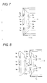
Fig. 7 is a partial top plan view illustrating the rear frame to which the light reflective sheet and the cover made of the light reflective sheet are attached; -
Fig. 8 is a partial exploded top plan view illustrating the rear frame to which another light reflective sheet is attached, and a cover made of another light reflective sheet; -
Fig. 9 is a partial exploded perspective view illustrating a first fixture; -
Fig. 10 is a partial cross-sectional view illustrating the first fixture where an upper edge portion of a cover made of a light reflective sheet is fixed to a support plate portion of a rear frame; -
Fig. 11 is a partial exploded perspective view illustrating a second fixture; -
Fig. 12 is a partial exploded perspective view illustrating a third fixture; -
Fig. 13 is a partial top plan view illustrating the third fixture where an upper edge portion of a cover made of a light reflective sheet is fixed to a support plate portion of a rear frame; and -
Fig. 14 is a partial cross-sectional view illustrating the third fixture where the upper edge portion of the cover made of the light reflective sheet is fixed to the support plate portion of the rear frame. - A liquid crystal module shown in
Figs. 1 to 5 includes arear frame 1, a lightreflective sheet 2, U-shapedcold cathode tubes 3,lamp holders 4, covers 5 made of light reflective sheets,optical sheets spacers 7,cell guides 8, aliquid crystal panel 9,bezels 10a and lOb. - Explaining the outline of the whole configuration of this liquid crystal module, the
rear frame 1 is a shallow box-type rear frame formed by bending a sheet metal, and the lightreflective sheet 2 is provided in therear frame 1. A plurality (two in this embodiment) of U-shapedcold cathode tubes 3 are arranged in parallel with each other on the lightreflective sheet 2. The U-shapedcold cathode tubes 3 are supported by a plurality (two in this embodiment) oflamp holders 4. Thelamp holder 4 is provided with holdingportions 4a which fixes and holds the U-shapedcold cathode tube 3, as shown inFig. 1 . Thelamp holders 4 holding center portions of the U-shapedcold cathode tubes 3 are provided with posts 4b supporting theoptical sheet 6a from below to prevent bending of theoptical sheet 6a. -
Lamp sockets 3a are attached to end portions of the U-shapedcold cathode tubes 3. Thelamp sockets 3a are fixed into socket opening portions (not shown) which are provided in abottom plate 1b of therear frame 1 along one of the left andright side plates 1a (along theright side plate 1a in this embodiment) of therear frame 1. Alead wire 3b of the U-shapedcold cathode tube 3 is drawn out from each of thelamp sockets 3a toward a rear side of therear frame 1. - As shown in
Figs. 3 and4 , both ends of the U-shapedcold cathode tube 3 are covered by thecovers 5 made of a light reflective sheet and disposed inside left andright side plates 1a of therear frame 1 to prevent variation in brightness from occurring at both left and right side portions of the display surface of theliquid crystal panel 9 and to improve the brightness at both left and right side portions of the display surface. The shape and attaching structure of thecovers 5 will be described in detail later. - As shown in
Figs. 1 ,3 and4 , the left and right edge portions of theoptical sheets upper edge portions 5b of thecovers 5 and left and right edge portions of theliquid crystal panel 9 are overlapped thereon with the band-shapedspacers 7 having a light shielding property interposed therebetween. As shown inFigs. 1 and5 , the upper and lower edge portions of theoptical sheets lower side plates 1c (double side plates bent in a reversed U-shape) of therear frame 1 and are pressed by the cell guides 8. The upper and lower edge portions of theliquid crystal panel 9 are disposed on the cell guides 8. Four peripheral edges of theliquid crystal panel 9 and four peripheral side plates of therear frame 1 are enclosed by two long-side bezels 10a and two short-side bezels 10b which are made of sheet metals and are connected in the shape of a rectangular frame. Thesebezels side plates 1c of therear frame 1 by screws 11 (seeFig. 5 ). - The
optical sheets cold cathode tubes 3 and uniformly irradiating it onto theliquid crystal panel 9. The upperoptical sheet 6b is a thin light diffuser sheet and the loweroptical sheet 6a is a panel-type light diffuser sheet (light diffusing plate) having a thickness sufficient enough to prevent it from bending. In addition, as shown inFigs. 1 and5 , anX-wiring board 9b is connected to the upper edge of theliquid crystal panel 9, with a chip-onfilm 9a interposed therebetween, and theX-wiring board 9b is fixed to the side surface of thecell guide 8. - The
cover 5 is made of the same light reflective sheet as the lightreflective sheet 2 provided on thebottom plate 1b of therear frame 1. This light reflective sheet is formed by laminating an aluminum deposited film on a surface of a substrate sheet, is inexpensive and has excellent light reflectivity. As shown inFigs. 3 ,4 and6 , eachcover 5 includes aninclined sheet portion 5a which is inclined downwardly toward the inside of therear frame 1, anupper edge portion 5b bent outwardly from an upper end of theinclined sheet portion 5a, and tworectangular insertion pieces 5c protruded inwardly from a lower end of theinclined sheet portion 5a. The lower end of theinclined sheet portion 5a is provided with a plurality (four in this embodiment) ofconcave portions 5d through which the U-shapedcold cathode tubes 3 are inserted. - The lower end of the
cover 5 is fixed to therear frame 1 by inserting theinsertion pieces 5c between thebottom plate 1b of therear frame 1 and the lightreflective sheet 2 through tworectangular cut portions 2a formed at both left and right end portions of the lightreflective sheet 2 which is provided at thebottom plate 1b of therear frame 1, as shown inFigs. 1 ,4 ,6 and7 . - The
insertion piece 5c and thecut portion 1e are not limited to the above-mentioned rectangular shape. For example, as shown inFig. 8 , hook-shapedinsertion pieces 5c and hook-shapedcut portions 2a may be provided. The lower end of thecover 5 may be fixed to therear frame 1 by inserting the hook-shapedinsertion pieces 5c between thebottom plate 1b of therear frame 1 and the lightreflective sheet 2 in a bending direction of a hook shape through thecut portions 2a. - In addition, the
upper edge portion 5b of thecover 5 is fixed to support plate portions I d which are bent inwardly at a right angle from the upper edges of the left andright side plates 1a of therear frame 1 by a first fixing means which will be described below. As shown inFig. 6 , a protrudingpiece 1e constituting the first fixing means is formed on thesupport plate portion 1d of therear frame 1. The protrudingpiece 1e is disposed at a position shifted from a center to one side in a longitudinal direction of thesupport plate portion 1d and protruded upwardly from thesupport plate portion 1d. The protrudingpiece 1e is formed by cutting a portion of thesupport plate portion 1d and upwardly bent the cut portion. In addition, arectangular hole 5e constituting the first fixing means and corresponding to the protrudingpiece 1e is formed in theupper edge portion 5b of thecover 5. The protrudingpiece 1e is inserted into therectangular hole 5e from below so that theupper edge portion 5b of the cover is fixed to thesupport plate portion 1d of therear frame 1. In this embodiment, tworectangular holes 5e are formed at symmetric positions shifted from a center to both sides in a longitudinal direction of theupper edge portion 5b of thecover 5. With this configuration, the left andright covers 5 can be formed in the same shape with each other and thus an attachment error of the left andright covers 5 to the left andright side plates 1a of therear frame 1 can be prevented. - In the liquid crystal module according to this embodiment, as shown in
Fig. 9 , the length L of the short side of therectangular hole 5e is slightly smaller than the thickness T of the protrudingpiece 1e so that the protrudingpiece 1e can be press-fitted into therectangular hole 5e. In addition, therectangular hole 5e is provided withnotches 5f extending in a short side direction of therectangular hole 5e from both ends of therectangular hole 5e in a long side direction of therectangular hole 5e. With this configuration, as shown inFig. 10 , when the protrudingpiece 1e is inserted into therectangular hole 5e, ahole edge portion 5g of therectangular hole 5e formed with the notch can be upwardly deformed. Therefore, the protrudingpiece 1e can be easily press-fitted into therectangular hole 5e and firmly fixed to theupper edge portion 5b of thecover 5. And thus, the protrudingpiece 1e is prevented from being released (detached) from therectangular hole 5e. - The
upper edge portion 5b of thecover 5 may be fixed to thesupport plate portion 1d of the rear frame by a second fixing means, as shown inFig. 11 . The second fixing means has a protrudingpiece 1e which is formed on thesupport plate portion 1d of therear frame 1 and protruded upwardly from thesupport plate portion 1d of therear frame 1 and a rectangularconcave cutout portion 5h which is formed at an outer end of theupper edge portion 5b of thecover 5. The protrudingpiece 1e is fitted into theconcave cutout portion 5h so that theupper edge portion 5b of thecover 5 is fixed to thesupport plate portion 1d of therear frame 1. - In the second fixing means, the width W5 of the
concave cutout portion 5h is slightly smaller than the width W1 of the protrudingpiece 1e e so that the protrudingpiece 1e can be press-fitted into theconcave cutout portion 5h. In addition, both sides of an opened end of theconcave cutout portion 5h are chamfered to formround portions 5i for receiving the protrudingpiece 1e. Accordingly, the protrudingpiece 1e can be smoothly fixed and fitted into theconcave cutout portion 5h, thereby improving the fixing strength and the fixing (fitting) workability. Theupper edge portion 5b of thecover 5 may be fixed and attached to thesupport plate portion 1d of therear frame 1 by double-sided tape or the like, in addition to the second fixing means to further improve the fixing strength. - The
upper edge portion 5b of thecover 5 may be fixed to thesupport plate portion 1d of therear frame 1 by a third fixing means, as shown inFigs. 12 and13 . The third fixing means includes atab piece 5j. Thistub piece 5j can be formed by forming aU-shaped slit portion 5k at theupper edge portion 5b of thecover 5. Theslit portion 5k extends in a longitudinal direction of theupper edge portion 5b and has both ends which are bent outwardly. The third fixing means further includes arectangular opening 1f f formed in thesupport plate portion 1d of therear frame 1. As shown inFigs. 13 and 14 , thetab piece 5j is inserted below thesupport plate portion 1d of therear frame 1 through theopening 1f of thesupport plate portion 1d so that theupper edge portion 5b of thecover 5 is fixed to thesupport plate portion 1d of therear frame 1. In the third fixing means, thetab piece 5j can be easily inserted into theopening 1f and theupper edge portion 5b of thecover 5 can be reliably fixed since thetab piece 5j is not easily released from theopening 1f. - As shown in
Figs. 1 and6 , thesupport plate portion 1d of therear frame 1 is provided withfirst uprising pieces 1g for positioning theliquid crystal panel 9. Corresponding to thesefirst uprising pieces 1g, theupper edge portion 5b of thecover 5 is provided withsecond uprising pieces 5m. Thesecond uprising piece 5m is overlapped with an inner surface of the correspondingfirst uprising piece 1g, as shown inFig. 4 . The left and right edge portions of theliquid crystal panel 9 are adjacent to thesecond uprising pieces 5m, and are positioned in left and right direction by thefirst uprising pieces 1g through thesecond uprising pieces 5m. If the left and right edge portions of theliquid crystal panel 9 are positioned in this way, since the left and right edge portions of theliquid crystal panel 9 do not come into direct contact with thefirst uprising pieces 1g made of sheet metal, it is possible to prevent the edge portions of theliquid crystal panel 9 from being damaged due to thefirst uprising pieces 1g. In addition, the left and right edge portions of theoptical sheets first uprising pieces 1g. In this case, the upper edge portion and the lower edge portion of theliquid crystal panel 9 are positioned by positioningbosses 8a protruded from both ends of thecell guide 8, as shown inFigs. 1 and5 . - The left and right edge portions of the
liquid crystal panel 9 are disposed on the band-shape spacer 7 having the light shielding property as mentioned above in this embodiment. The cell guide may be used instead of thespacer 7. In this case, the cell guide presses the left and right end portions of theoptical sheets liquid crystal panel 9. However, in the case where the left and right edge portions of theliquid crystal panel 9 are supported by thespacer 7 having the light shielding property as like this embodiment, since thespacer 7 is inexpensive, it is possible to lower costs. In addition, since thespacer 7 has the light shielding property, it is possible to prevent light from leaking from the left and right edge portions of theliquid crystal panel 9. - In the above-described liquid crystal module, since the end portions of the U-shaped
cold cathode tubes 3 are concealed by thecovers right side plates 1a of therear frame 1, it is possible to prevent variation in brightness from occurring at both left and right side portions of the display surface of theliquid crystal panel 9. In addition, since thecover 5 made of the light reflective sheet costs significantly less than the lamp frame and thecover 5 has the excellent light reflectivity, it is possible to lower the cost of the liquid crystal module and improve the brightness at both left and right side portions of the display surface of theliquid crystal panel 9. Moreover, since the lower end portion of thecover 5 can be fixed by inserting theinsertion pieces 5c of thecover 5 between thebottom plate 1b of therear frame 1 and the lightreflective sheet 2 through thecut portions 2a formed at both left and right end portions of the lightreflective sheet 2 which is provided at thebottom plate 1b of therear frame 1, it is very easy to fix the lower end portion of thecover 5 to therear frame 1 and it is possible to firmly fix the lower end portion of thecover 5. Further, since theupper edge portion 5b of thecover 5 is simply and reliably fixed to thesupport plate portion 1d of therear frame 1 by the above-mentioned first, second and third fixing means, there are some positive effects in that the fixing (assembly) workability of thecover 5 made of the light reflective sheet become good without no concerns that thecover 5 may be released (detached) from therear frame 1. - While the present invention has been shown and described with reference to certain exemplary embodiments thereof, it will be understood by those skilled in the art that various changes in form and details may be made therein without departing from the spirit and scope of the invention as defined by the appended claims.
Claims (9)
- A liquid crystal module, comprising:a rear frame;a light reflective sheet provided on a bottom plate of the rear frame;a cold cathode tube provided on the light reflective sheet in the rear frame;a pair of left and right covers made of the light reflective sheet and disposed inside left and right side plates of the rear frame to cover over both end portions of the cold cathode tube,wherein each of the covers includes:an inclined sheet portion inclined downwardly toward the inside of the rear frame;an upper edge portion bent outwardly from an upper end of the inclined sheet portion; anda insertion piece protruded inwardly from a lower end of the inclined sheet portion,wherein the upper edge portion is mounted on a support plate portion provided in an upper end of each of the left and right side plates of the rear frame and fixed to the support plate portion with a fixture, andwherein the insertion piece is inserted and fixed between the bottom plate of the rear frame and the light reflective sheet through a cut portion formed at each of left and right end portions of the light reflective sheet.
- The liquid crystal module as set forth in claim 1,
wherein the fixture includes a protrusion piece protruded upwardly from the support plate portion of the rear frame and a rectangular hole formed on the upper edge portion of the covers, and
wherein the protrusion piece is inserted into the rectangular hole from below so that the upper edge portion of the covers is fixed to the support plate portion of the rear frame. - The liquid crystal module as set forth in claim 2, wherein the length of a short side of the rectangular hole is slightly smaller than the thickness of the protrusion piece so that the protrusion piece is press-fitted into the rectangular hole from below.
- The liquid crystal module as set forth in claim 3, wherein the rectangular hole is provided with notches extending in a short side direction of the rectangular hole from both ends of the rectangular hole in a long side direction of the rectangular hole.
- The liquid crystal module as set forth in claim 1,
wherein the fixture includes a protrusion piece protruded upwardly from the support plate portion of the rear frame and a concave cutout portion formed at outer end of the upper edge portion of the covers, and
wherein the protrusion piece is fitted into the concave cutout portion so that the upper edge portion of the covers is fixed to the support plate portion of the rear frame. - The liquid crystal module as set forth in claim 5, wherein the width of the concave cutout portion is slightly smaller than the width of the protrusion piece so that the protrusion piece is press-fitted into the concave cutout portion.
- The liquid crystal module as set forth in claim 5, wherein both sides of an opened end of the concave cutout portion are chamfered for fitting the protrusion piece into the concave cutout portion.
- The liquid crystal module as set forth in claim 1,
wherein the fixture includes a rectangular opening formed in the support plate portion of the rear frame and a tub piece formed in the upper edge portion of the covers by forming a slit portion at the upper edge portion of the covers, the slit portion extending in a longitudinal direction of the upper edge portion and having both ends bent outwardly, and
wherein the tub piece is inserted below the support plate portion of the rear frame through the rectangular opening so that the upper edge portion of the covers is fixed to the support plate portion of the rear frame. - The liquid crystal module as set forth in claim 1, further comprising:an optical sheet overlapped with the upper edge portion of the covers;a spacer provided on left and right edge portions of the optical sheet; anda liquid crystal panel overlapped with the optical sheet through the spacer,wherein the support plate portion of the rear frame is provided with a first uprising piece and the upper edge portion of the covers is provided with a second uprising piece overlapped with an inner surface of the first uprising piece,wherein the liquid crystal panel is positioned in left and right direction by the first uprising piece through the second uprising piece.
Priority Applications (1)
| Application Number | Priority Date | Filing Date | Title |
|---|---|---|---|
| PL10164073T PL2261732T3 (en) | 2009-06-05 | 2010-05-27 | Liquid crystal module |
Applications Claiming Priority (1)
| Application Number | Priority Date | Filing Date | Title |
|---|---|---|---|
| JP2009135749A JP2010282856A (en) | 2009-06-05 | 2009-06-05 | LCD module |
Publications (2)
| Publication Number | Publication Date |
|---|---|
| EP2261732A1 true EP2261732A1 (en) | 2010-12-15 |
| EP2261732B1 EP2261732B1 (en) | 2012-07-11 |
Family
ID=42711961
Family Applications (1)
| Application Number | Title | Priority Date | Filing Date |
|---|---|---|---|
| EP10164073A Not-in-force EP2261732B1 (en) | 2009-06-05 | 2010-05-27 | Liquid crystal module |
Country Status (4)
| Country | Link |
|---|---|
| US (1) | US8174644B2 (en) |
| EP (1) | EP2261732B1 (en) |
| JP (1) | JP2010282856A (en) |
| PL (1) | PL2261732T3 (en) |
Families Citing this family (6)
| Publication number | Priority date | Publication date | Assignee | Title |
|---|---|---|---|---|
| EP2343197B1 (en) * | 2010-01-12 | 2012-12-19 | Lanybook GmbH | A book with an elastic strap band |
| CN102392993B (en) * | 2011-11-18 | 2014-02-05 | 深圳市华星光电技术有限公司 | Back frame and backlight system of panel display device |
| JP5868161B2 (en) * | 2011-12-20 | 2016-02-24 | キヤノン株式会社 | Display device |
| TWI432850B (en) * | 2011-12-30 | 2014-04-01 | Au Optronics Corp | Direct type backlight module and display panel using the same |
| WO2015015558A1 (en) * | 2013-07-30 | 2015-02-05 | 堺ディスプレイプロダクト株式会社 | Light source apparatus and display apparatus |
| CN112068353A (en) * | 2020-09-09 | 2020-12-11 | 深圳创维-Rgb电子有限公司 | Liquid crystal display module and liquid crystal splicing screen |
Citations (6)
| Publication number | Priority date | Publication date | Assignee | Title |
|---|---|---|---|---|
| JP2005322645A (en) | 2004-05-07 | 2005-11-17 | Samsung Electronics Co Ltd | Backlight assembly with simplified structure and display device having the same |
| US20060215386A1 (en) * | 2003-09-19 | 2006-09-28 | Masato Hatanaka | Backlight device and liquid crystal display |
| EP2006603A1 (en) * | 2007-06-21 | 2008-12-24 | Funai Electric Co., Ltd. | Liquid crystal module |
| US20080316387A1 (en) * | 2007-06-21 | 2008-12-25 | Funai Electric Co., Ltd. | Liquid crystal module |
| US20080316389A1 (en) * | 2007-06-21 | 2008-12-25 | Funai Electric Co., Ltd. | Liquid crystal module |
| EP2045653A1 (en) * | 2007-10-04 | 2009-04-08 | Funai Electric Co., Ltd. | Liquid crystal module |
Family Cites Families (1)
| Publication number | Priority date | Publication date | Assignee | Title |
|---|---|---|---|---|
| JP4842739B2 (en) * | 2006-09-01 | 2011-12-21 | 株式会社 日立ディスプレイズ | Display device |
-
2009
- 2009-06-05 JP JP2009135749A patent/JP2010282856A/en active Pending
-
2010
- 2010-05-27 PL PL10164073T patent/PL2261732T3/en unknown
- 2010-05-27 EP EP10164073A patent/EP2261732B1/en not_active Not-in-force
- 2010-06-02 US US12/792,210 patent/US8174644B2/en not_active Expired - Fee Related
Patent Citations (7)
| Publication number | Priority date | Publication date | Assignee | Title |
|---|---|---|---|---|
| US20060215386A1 (en) * | 2003-09-19 | 2006-09-28 | Masato Hatanaka | Backlight device and liquid crystal display |
| JP2005322645A (en) | 2004-05-07 | 2005-11-17 | Samsung Electronics Co Ltd | Backlight assembly with simplified structure and display device having the same |
| US20050265020A1 (en) * | 2004-05-07 | 2005-12-01 | Yong-Il Kim | Backlight assembly with simplified structure and display device provided with the same |
| EP2006603A1 (en) * | 2007-06-21 | 2008-12-24 | Funai Electric Co., Ltd. | Liquid crystal module |
| US20080316387A1 (en) * | 2007-06-21 | 2008-12-25 | Funai Electric Co., Ltd. | Liquid crystal module |
| US20080316389A1 (en) * | 2007-06-21 | 2008-12-25 | Funai Electric Co., Ltd. | Liquid crystal module |
| EP2045653A1 (en) * | 2007-10-04 | 2009-04-08 | Funai Electric Co., Ltd. | Liquid crystal module |
Also Published As
| Publication number | Publication date |
|---|---|
| EP2261732B1 (en) | 2012-07-11 |
| US20100309408A1 (en) | 2010-12-09 |
| PL2261732T3 (en) | 2012-12-31 |
| US8174644B2 (en) | 2012-05-08 |
| JP2010282856A (en) | 2010-12-16 |
Similar Documents
| Publication | Publication Date | Title |
|---|---|---|
| JP4915354B2 (en) | LCD module | |
| US8587744B2 (en) | Liquid crystal display and fabricating method thereof | |
| US7764335B2 (en) | Liquid crystal module | |
| US7929073B2 (en) | Liquid crystal display module and method for assembling the same | |
| EP2006729B1 (en) | Liquid crystal module | |
| KR101288600B1 (en) | Back light unit for liquid crystal display device | |
| US8462291B2 (en) | Backlight module with film positioning function and display device using the same | |
| EP2390712A1 (en) | Backlight unit and display device including the same | |
| EP2261732B1 (en) | Liquid crystal module | |
| US8902376B2 (en) | Backlight module and display device using the same | |
| JP2007280770A (en) | Surface light source device and liquid crystal display device using the same | |
| CN103075676B (en) | Back light unit, method of manufacturing the same and liquid crystal display device including the same | |
| US20100321605A1 (en) | Liquid crystal module | |
| US8827481B2 (en) | Illumination device, display device, and television reception device | |
| EP2214051B1 (en) | Liquid crystal module | |
| US8305521B2 (en) | Liquid crystal module | |
| EP2006730B1 (en) | Liquid crystal display device with improved backlight assembly | |
| JP2008292886A (en) | LCD module | |
| JP5050876B2 (en) | LCD module | |
| JP2005285535A (en) | Illumination unit and liquid crystal display device using the same | |
| US20100002417A1 (en) | Back bezel for use in a backlight module structure, the backlight module structure, and the method for manufacturing the back bezel | |
| US20110001893A1 (en) | Illumination device, display device, and television receiver apparatus | |
| JP4534552B2 (en) | Liquid crystal display | |
| KR20060062051A (en) | LCD and its assembly method | |
| JP2002287648A (en) | Backlight for display device and display device having the same |
Legal Events
| Date | Code | Title | Description |
|---|---|---|---|
| PUAI | Public reference made under article 153(3) epc to a published international application that has entered the european phase |
Free format text: ORIGINAL CODE: 0009012 |
|
| AK | Designated contracting states |
Kind code of ref document: A1 Designated state(s): AL AT BE BG CH CY CZ DE DK EE ES FI FR GB GR HR HU IE IS IT LI LT LU LV MC MK MT NL NO PL PT RO SE SI SK SM TR |
|
| AX | Request for extension of the european patent |
Extension state: BA ME RS |
|
| 17P | Request for examination filed |
Effective date: 20110615 |
|
| GRAP | Despatch of communication of intention to grant a patent |
Free format text: ORIGINAL CODE: EPIDOSNIGR1 |
|
| RIN1 | Information on inventor provided before grant (corrected) |
Inventor name: FUKUDA, YUTAKA |
|
| GRAS | Grant fee paid |
Free format text: ORIGINAL CODE: EPIDOSNIGR3 |
|
| GRAA | (expected) grant |
Free format text: ORIGINAL CODE: 0009210 |
|
| AK | Designated contracting states |
Kind code of ref document: B1 Designated state(s): AL AT BE BG CH CY CZ DE DK EE ES FI FR GB GR HR HU IE IS IT LI LT LU LV MC MK MT NL NO PL PT RO SE SI SK SM TR |
|
| REG | Reference to a national code |
Ref country code: GB Ref legal event code: FG4D |
|
| REG | Reference to a national code |
Ref country code: CH Ref legal event code: EP |
|
| REG | Reference to a national code |
Ref country code: AT Ref legal event code: REF Ref document number: 566411 Country of ref document: AT Kind code of ref document: T Effective date: 20120715 |
|
| REG | Reference to a national code |
Ref country code: IE Ref legal event code: FG4D |
|
| REG | Reference to a national code |
Ref country code: DE Ref legal event code: R096 Ref document number: 602010002149 Country of ref document: DE Effective date: 20120906 |
|
| REG | Reference to a national code |
Ref country code: NL Ref legal event code: VDEP Effective date: 20120711 |
|
| REG | Reference to a national code |
Ref country code: AT Ref legal event code: MK05 Ref document number: 566411 Country of ref document: AT Kind code of ref document: T Effective date: 20120711 |
|
| REG | Reference to a national code |
Ref country code: LT Ref legal event code: MG4D Effective date: 20120711 |
|
| REG | Reference to a national code |
Ref country code: PL Ref legal event code: T3 |
|
| PG25 | Lapsed in a contracting state [announced via postgrant information from national office to epo] |
Ref country code: NO Free format text: LAPSE BECAUSE OF FAILURE TO SUBMIT A TRANSLATION OF THE DESCRIPTION OR TO PAY THE FEE WITHIN THE PRESCRIBED TIME-LIMIT Effective date: 20121011 Ref country code: FI Free format text: LAPSE BECAUSE OF FAILURE TO SUBMIT A TRANSLATION OF THE DESCRIPTION OR TO PAY THE FEE WITHIN THE PRESCRIBED TIME-LIMIT Effective date: 20120711 Ref country code: HR Free format text: LAPSE BECAUSE OF FAILURE TO SUBMIT A TRANSLATION OF THE DESCRIPTION OR TO PAY THE FEE WITHIN THE PRESCRIBED TIME-LIMIT Effective date: 20120711 Ref country code: CY Free format text: LAPSE BECAUSE OF FAILURE TO SUBMIT A TRANSLATION OF THE DESCRIPTION OR TO PAY THE FEE WITHIN THE PRESCRIBED TIME-LIMIT Effective date: 20120711 Ref country code: AT Free format text: LAPSE BECAUSE OF FAILURE TO SUBMIT A TRANSLATION OF THE DESCRIPTION OR TO PAY THE FEE WITHIN THE PRESCRIBED TIME-LIMIT Effective date: 20120711 Ref country code: IS Free format text: LAPSE BECAUSE OF FAILURE TO SUBMIT A TRANSLATION OF THE DESCRIPTION OR TO PAY THE FEE WITHIN THE PRESCRIBED TIME-LIMIT Effective date: 20121111 Ref country code: BE Free format text: LAPSE BECAUSE OF FAILURE TO SUBMIT A TRANSLATION OF THE DESCRIPTION OR TO PAY THE FEE WITHIN THE PRESCRIBED TIME-LIMIT Effective date: 20120711 Ref country code: LT Free format text: LAPSE BECAUSE OF FAILURE TO SUBMIT A TRANSLATION OF THE DESCRIPTION OR TO PAY THE FEE WITHIN THE PRESCRIBED TIME-LIMIT Effective date: 20120711 |
|
| PG25 | Lapsed in a contracting state [announced via postgrant information from national office to epo] |
Ref country code: SI Free format text: LAPSE BECAUSE OF FAILURE TO SUBMIT A TRANSLATION OF THE DESCRIPTION OR TO PAY THE FEE WITHIN THE PRESCRIBED TIME-LIMIT Effective date: 20120711 Ref country code: GR Free format text: LAPSE BECAUSE OF FAILURE TO SUBMIT A TRANSLATION OF THE DESCRIPTION OR TO PAY THE FEE WITHIN THE PRESCRIBED TIME-LIMIT Effective date: 20121012 Ref country code: PT Free format text: LAPSE BECAUSE OF FAILURE TO SUBMIT A TRANSLATION OF THE DESCRIPTION OR TO PAY THE FEE WITHIN THE PRESCRIBED TIME-LIMIT Effective date: 20121112 Ref country code: SE Free format text: LAPSE BECAUSE OF FAILURE TO SUBMIT A TRANSLATION OF THE DESCRIPTION OR TO PAY THE FEE WITHIN THE PRESCRIBED TIME-LIMIT Effective date: 20120711 Ref country code: LV Free format text: LAPSE BECAUSE OF FAILURE TO SUBMIT A TRANSLATION OF THE DESCRIPTION OR TO PAY THE FEE WITHIN THE PRESCRIBED TIME-LIMIT Effective date: 20120711 |
|
| PG25 | Lapsed in a contracting state [announced via postgrant information from national office to epo] |
Ref country code: NL Free format text: LAPSE BECAUSE OF FAILURE TO SUBMIT A TRANSLATION OF THE DESCRIPTION OR TO PAY THE FEE WITHIN THE PRESCRIBED TIME-LIMIT Effective date: 20120711 |
|
| PG25 | Lapsed in a contracting state [announced via postgrant information from national office to epo] |
Ref country code: EE Free format text: LAPSE BECAUSE OF FAILURE TO SUBMIT A TRANSLATION OF THE DESCRIPTION OR TO PAY THE FEE WITHIN THE PRESCRIBED TIME-LIMIT Effective date: 20120711 Ref country code: RO Free format text: LAPSE BECAUSE OF FAILURE TO SUBMIT A TRANSLATION OF THE DESCRIPTION OR TO PAY THE FEE WITHIN THE PRESCRIBED TIME-LIMIT Effective date: 20120711 Ref country code: CZ Free format text: LAPSE BECAUSE OF FAILURE TO SUBMIT A TRANSLATION OF THE DESCRIPTION OR TO PAY THE FEE WITHIN THE PRESCRIBED TIME-LIMIT Effective date: 20120711 Ref country code: DK Free format text: LAPSE BECAUSE OF FAILURE TO SUBMIT A TRANSLATION OF THE DESCRIPTION OR TO PAY THE FEE WITHIN THE PRESCRIBED TIME-LIMIT Effective date: 20120711 Ref country code: ES Free format text: LAPSE BECAUSE OF FAILURE TO SUBMIT A TRANSLATION OF THE DESCRIPTION OR TO PAY THE FEE WITHIN THE PRESCRIBED TIME-LIMIT Effective date: 20121022 |
|
| PLBE | No opposition filed within time limit |
Free format text: ORIGINAL CODE: 0009261 |
|
| STAA | Information on the status of an ep patent application or granted ep patent |
Free format text: STATUS: NO OPPOSITION FILED WITHIN TIME LIMIT |
|
| PG25 | Lapsed in a contracting state [announced via postgrant information from national office to epo] |
Ref country code: IT Free format text: LAPSE BECAUSE OF FAILURE TO SUBMIT A TRANSLATION OF THE DESCRIPTION OR TO PAY THE FEE WITHIN THE PRESCRIBED TIME-LIMIT Effective date: 20120711 Ref country code: SK Free format text: LAPSE BECAUSE OF FAILURE TO SUBMIT A TRANSLATION OF THE DESCRIPTION OR TO PAY THE FEE WITHIN THE PRESCRIBED TIME-LIMIT Effective date: 20120711 |
|
| 26N | No opposition filed |
Effective date: 20130412 |
|
| PG25 | Lapsed in a contracting state [announced via postgrant information from national office to epo] |
Ref country code: BG Free format text: LAPSE BECAUSE OF FAILURE TO SUBMIT A TRANSLATION OF THE DESCRIPTION OR TO PAY THE FEE WITHIN THE PRESCRIBED TIME-LIMIT Effective date: 20121011 |
|
| REG | Reference to a national code |
Ref country code: DE Ref legal event code: R097 Ref document number: 602010002149 Country of ref document: DE Effective date: 20130412 |
|
| PG25 | Lapsed in a contracting state [announced via postgrant information from national office to epo] |
Ref country code: MC Free format text: LAPSE BECAUSE OF FAILURE TO SUBMIT A TRANSLATION OF THE DESCRIPTION OR TO PAY THE FEE WITHIN THE PRESCRIBED TIME-LIMIT Effective date: 20120711 |
|
| REG | Reference to a national code |
Ref country code: IE Ref legal event code: MM4A |
|
| PG25 | Lapsed in a contracting state [announced via postgrant information from national office to epo] |
Ref country code: IE Free format text: LAPSE BECAUSE OF NON-PAYMENT OF DUE FEES Effective date: 20130527 |
|
| REG | Reference to a national code |
Ref country code: CH Ref legal event code: PL |
|
| PG25 | Lapsed in a contracting state [announced via postgrant information from national office to epo] |
Ref country code: LI Free format text: LAPSE BECAUSE OF NON-PAYMENT OF DUE FEES Effective date: 20140531 Ref country code: CH Free format text: LAPSE BECAUSE OF NON-PAYMENT OF DUE FEES Effective date: 20140531 |
|
| PG25 | Lapsed in a contracting state [announced via postgrant information from national office to epo] |
Ref country code: MT Free format text: LAPSE BECAUSE OF FAILURE TO SUBMIT A TRANSLATION OF THE DESCRIPTION OR TO PAY THE FEE WITHIN THE PRESCRIBED TIME-LIMIT Effective date: 20120711 |
|
| REG | Reference to a national code |
Ref country code: FR Ref legal event code: PLFP Year of fee payment: 6 |
|
| PG25 | Lapsed in a contracting state [announced via postgrant information from national office to epo] |
Ref country code: SM Free format text: LAPSE BECAUSE OF FAILURE TO SUBMIT A TRANSLATION OF THE DESCRIPTION OR TO PAY THE FEE WITHIN THE PRESCRIBED TIME-LIMIT Effective date: 20120711 |
|
| PGFP | Annual fee paid to national office [announced via postgrant information from national office to epo] |
Ref country code: PL Payment date: 20150327 Year of fee payment: 6 |
|
| PG25 | Lapsed in a contracting state [announced via postgrant information from national office to epo] |
Ref country code: TR Free format text: LAPSE BECAUSE OF FAILURE TO SUBMIT A TRANSLATION OF THE DESCRIPTION OR TO PAY THE FEE WITHIN THE PRESCRIBED TIME-LIMIT Effective date: 20120711 |
|
| PG25 | Lapsed in a contracting state [announced via postgrant information from national office to epo] |
Ref country code: MK Free format text: LAPSE BECAUSE OF FAILURE TO SUBMIT A TRANSLATION OF THE DESCRIPTION OR TO PAY THE FEE WITHIN THE PRESCRIBED TIME-LIMIT Effective date: 20120711 Ref country code: LU Free format text: LAPSE BECAUSE OF NON-PAYMENT OF DUE FEES Effective date: 20130527 Ref country code: HU Free format text: LAPSE BECAUSE OF FAILURE TO SUBMIT A TRANSLATION OF THE DESCRIPTION OR TO PAY THE FEE WITHIN THE PRESCRIBED TIME-LIMIT; INVALID AB INITIO Effective date: 20100527 |
|
| PGFP | Annual fee paid to national office [announced via postgrant information from national office to epo] |
Ref country code: DE Payment date: 20150519 Year of fee payment: 6 Ref country code: GB Payment date: 20150527 Year of fee payment: 6 |
|
| PGFP | Annual fee paid to national office [announced via postgrant information from national office to epo] |
Ref country code: FR Payment date: 20150508 Year of fee payment: 6 |
|
| REG | Reference to a national code |
Ref country code: DE Ref legal event code: R119 Ref document number: 602010002149 Country of ref document: DE |
|
| GBPC | Gb: european patent ceased through non-payment of renewal fee |
Effective date: 20160527 |
|
| REG | Reference to a national code |
Ref country code: FR Ref legal event code: ST Effective date: 20170131 |
|
| PG25 | Lapsed in a contracting state [announced via postgrant information from national office to epo] |
Ref country code: DE Free format text: LAPSE BECAUSE OF NON-PAYMENT OF DUE FEES Effective date: 20161201 Ref country code: FR Free format text: LAPSE BECAUSE OF NON-PAYMENT OF DUE FEES Effective date: 20160531 |
|
| PG25 | Lapsed in a contracting state [announced via postgrant information from national office to epo] |
Ref country code: GB Free format text: LAPSE BECAUSE OF NON-PAYMENT OF DUE FEES Effective date: 20160527 |
|
| PG25 | Lapsed in a contracting state [announced via postgrant information from national office to epo] |
Ref country code: PL Free format text: LAPSE BECAUSE OF NON-PAYMENT OF DUE FEES Effective date: 20160527 |
|
| PG25 | Lapsed in a contracting state [announced via postgrant information from national office to epo] |
Ref country code: AL Free format text: LAPSE BECAUSE OF FAILURE TO SUBMIT A TRANSLATION OF THE DESCRIPTION OR TO PAY THE FEE WITHIN THE PRESCRIBED TIME-LIMIT Effective date: 20120711 |