EP2261494B1 - Vorrichtung zur Verringerung des Schadstoffanteils im Abgas von Verbrennungsmaschinen - Google Patents
Vorrichtung zur Verringerung des Schadstoffanteils im Abgas von Verbrennungsmaschinen Download PDFInfo
- Publication number
- EP2261494B1 EP2261494B1 EP09161661A EP09161661A EP2261494B1 EP 2261494 B1 EP2261494 B1 EP 2261494B1 EP 09161661 A EP09161661 A EP 09161661A EP 09161661 A EP09161661 A EP 09161661A EP 2261494 B1 EP2261494 B1 EP 2261494B1
- Authority
- EP
- European Patent Office
- Prior art keywords
- alloy body
- alloy
- fuel
- fluid
- weight
- Prior art date
- Legal status (The legal status is an assumption and is not a legal conclusion. Google has not performed a legal analysis and makes no representation as to the accuracy of the status listed.)
- Not-in-force
Links
Images
Classifications
-
- F—MECHANICAL ENGINEERING; LIGHTING; HEATING; WEAPONS; BLASTING
- F02—COMBUSTION ENGINES; HOT-GAS OR COMBUSTION-PRODUCT ENGINE PLANTS
- F02M—SUPPLYING COMBUSTION ENGINES IN GENERAL WITH COMBUSTIBLE MIXTURES OR CONSTITUENTS THEREOF
- F02M27/00—Apparatus for treating combustion-air, fuel, or fuel-air mixture, by catalysts, electric means, magnetism, rays, sound waves, or the like
- F02M27/02—Apparatus for treating combustion-air, fuel, or fuel-air mixture, by catalysts, electric means, magnetism, rays, sound waves, or the like by catalysts
-
- F—MECHANICAL ENGINEERING; LIGHTING; HEATING; WEAPONS; BLASTING
- F02—COMBUSTION ENGINES; HOT-GAS OR COMBUSTION-PRODUCT ENGINE PLANTS
- F02M—SUPPLYING COMBUSTION ENGINES IN GENERAL WITH COMBUSTIBLE MIXTURES OR CONSTITUENTS THEREOF
- F02M27/00—Apparatus for treating combustion-air, fuel, or fuel-air mixture, by catalysts, electric means, magnetism, rays, sound waves, or the like
- F02M27/04—Apparatus for treating combustion-air, fuel, or fuel-air mixture, by catalysts, electric means, magnetism, rays, sound waves, or the like by electric means, ionisation, polarisation or magnetism
- F02M27/045—Apparatus for treating combustion-air, fuel, or fuel-air mixture, by catalysts, electric means, magnetism, rays, sound waves, or the like by electric means, ionisation, polarisation or magnetism by permanent magnets
Definitions
- the present invention relates to a device for reducing at least one pollutant content in the exhaust gas of internal combustion engines, comprising a housing having at least one flow direction defining fluid channel extending from a fluid inlet to a fluid outlet, and at least one alloy body comprising tin as alloying substance Fluid channel is arranged so that it comes into contact with a guided through this fuel. Furthermore, the present invention relates to a method for reducing at least one pollutant content in the exhaust gas of internal combustion engines, in which a fuel before its entry into the internal combustion engine is at least partially brought into contact with at least one alloy body containing alloying alloy body.
- the apparatus includes an elongated hollow cylindrical housing defining a single fluid channel extending from a fluid inlet to a fluid outlet.
- two alloy body, a magnet and a spring element are successively arranged in the fluid channel, wherein the spring element is supported against the housing and biases the two alloy body and the magnet to prevent relative movement between the components.
- the alloy bodies have a gear-like structure and comprise a hub portion extending in the flow direction as well as a plurality of wing portions extending at an angle to the flow direction, which are fixedly connected to the hub portion and extend substantially radially outwardly therefrom.
- the two alloy bodies comprise, as alloy constituents, amalgam, tin, mercury and lead. Further, antimony may be provided as an alloying ingredient.
- the two free ends of the housing are closed with corresponding housing covers, each with a connection to the Connecting a flexible region of a fuel line are provided.
- the fuel is exposed to the magnetic field generated by the magnets, whereupon the fuel exits the housing and the injection system of the internal combustion engine is supplied.
- the enrichment of the fuel with trace elements of the alloy constituents of the alloy bodies and the provision of the fuel with an electric charge lead to an improvement of the combustion properties of the fuel within the internal combustion engine, in particular an improved performance and a reduced fuel consumption can be achieved.
- the conditioning of the fuel in the manner described above should reduce the pollutant components in the exhaust gas of the internal combustion engine. In this regard, however, so far only very small improvements have been detected, which is why other devices have prevailed to reduce the pollutant levels in the exhaust gas of internal combustion engines, such as catalysts, particulate filters or the like, which are used for exhaust aftertreatment.
- a major disadvantage of vehicle catalysts and particulate filters, however, is that they are structurally very complex and expensive.
- the present invention provides a device for reducing at least one pollutant content in the exhaust gas of internal combustion engines comprising a housing having at least one fluid passage defining a flow direction extending from a fluid inlet to a fluid outlet, at least one alloy body comprising tin and silver as an alloying constituent arranged in the fluid channel, that it comes into contact with a guided through this fuel, and at least one arranged in the fluid channel magnet which exposes the flowing through the fluid channel fuel to a magnetic field, characterized in that the tin content of the alloy body in the range from 69 to 72% by weight, and that the silver content of the alloy body is in the range of 8.5 to 9.5% by weight.
- the present invention turns away from the currently most promising technique for reducing pollutant levels in the exhaust of internal combustion engines in the form of catalysts and RuBpumblefiltem and uses the US-A-5,307,779 described technique, which was developed primarily for performance enhancement and fuel reduction.
- the modification of the alloy constituents of the alloy body in particular by the element silver instead of amalgam and mercury led to a surprisingly strong pollutant reduction in the exhaust gas.
- the proportion of soot particles in the exhaust gas of diesel vehicles could be considerably reduced, which will be explained in more detail below with reference to an embodiment.
- the tin content of the alloy body is in the range of 69-72% by weight. This area has proven to be particularly advantageous in the context of experiments.
- the silver content of the alloy body is in the range of 8.5-9.5 wt .-%, since particularly good results could be achieved in this area.
- the alloy body comprises antimony as an alloying ingredient, preferably at a level in the range of 15-19% by weight.
- the alloy body may comprise lead as alloying constituent, preferably with a content in the range of 2.85-3.5 wt.%.
- At least one magnet is arranged in the fluid channel, which exposes the fuel flowing through the fluid channel to a magnetic field, wherein the magnet is preferably an anisotropic magnet.
- Anisotropic magnets are characterized in particular in that they have a preferred direction of magnetization. Compared with isotropic magnets, the energy density is many times higher.
- the alloy body and / or the magnet may be biased within the fluid channel with a spring member to prevent movement of the components within the housing.
- the alloy body has one or more passage openings through which the fuel flows. In this way, a large contact surface is generated, with which the fuel can come into contact.
- the alloy body has a substantially in the direction of flow extending hub portion and a plurality of substantially in the direction of flow occidentalreckkende wing portions which are fixedly connected to the hub portion and extending substantially radially outwardly therefrom.
- the wing portions may extend at an angle to the flow direction and / or be bent in a plane transverse to the flow direction. In this way, on the one hand, the area of the alloy body coming into contact with the fuel is increased. On the other hand, a turbulence of the fuel takes place when passing through the alloy body, whereby the contact of the fuel with the alloy body is improved.
- the housing preferably has a connection for connecting a flexible region of a fuel line.
- Such connections can substantially facilitate the installation of the device according to the invention in a fuel line.
- the present invention provides a method for reducing at least one Schadstoffante ils in the exhaust gas of internal combustion engines, in which a fuel before entering the internal combustion engine is at least partially brought into contact with at least one tin and silver as alloying alloy body and in a further step Preferably, after having passed the at least one alloy body, it is exposed to a magnetic field to at least temporarily impart a predetermined electrical charge to the fuel prior to entering the injection system of the internal combustion engine.
- the method is characterized in that the tin content of the alloy body is in the range of 69-72 wt%, and that the silver content of the alloy body is in the range of 8.5-9.5 wt%
- the alloy body also contains antimony as an alloy constituent, preferably with a proportion in the range of 15-19% by weight.
- the alloy body may comprise lead as alloying constituent, preferably with a content in the range of 2.85-3.5 wt.%.
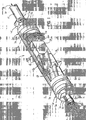
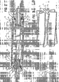
- FIGS. 1 to 4 show an apparatus 10 according to the present invention, which serves to reduce at least one pollutant content in the exhaust gas of internal combustion engines.
- the device 10 is installed in a fuel line 12 leading to an internal combustion engine, not shown, such as a vehicle engine or the like. The positioning of the device 10 takes place, if possible, in a section of the fuel line 12 immediately before the injection system of the internal combustion engine.
- the device 10 comprises a housing 14, which essentially consists of a tube-like housing section 16 of circular cross-section, which defines a fluid channel 18, and two housing covers 20, which close the opposite free ends of the housing section 16 in a fluid-tight manner.
- the housing covers 20 are each provided with a bore, which form a fluid inlet 22 and a fluid outlet 24 of the device 10.
- Each housing cover comprises an outer shoulder 26, which abuts against the end of the housing portion 16, and a peripheral portion 28 which is received in the housing portion 16 and sealed via an inserted into an annular groove 30 O-ring 32 relative to the housing portion 16.
- the housing cover 20 is circumferentially crimped radially inward at the position indicated by the reference numeral 34, preferably cold-crimped, wherein the position 34 lies in the region of the O-ring 32. Accordingly, not only a fixing of the housing cover 20 to the housing portion 16, but it is also the sealing effect between these components by the choice of the crimping position 34 improved.
- the housing cover 20 each include an internal thread 35 for receiving a connecting element 36 for connecting the device to the fuel line 12, wherein the connecting elements 36 are provided at their device 10 facing free ends with a corresponding external thread 38. Furthermore, the connecting elements 36 comprise a screw head 40 at the opposite end, on which a wrench can engage the device 10 during the fastening of the connecting element 36.
- the connecting elements are provided at their outwardly facing end in each case with a connection 42, via which a free end 44, 46 of the fuel line 12 can be slipped. The securing of the free ends 44, 46 at the terminals 42 is preferably carried out via corresponding hose clamps 48.
- Each connecting element 36 is provided with a through hole 50 through which fuel can flow.
- an O-ring 52 is provided between these components, which is presently arranged in a recess 54 provided for this purpose.
- two identical alloy bodies 56, an anisotropic magnet 58 and a spring element 60 are arranged in the direction of flow, which is indicated by the arrows indicated by the reference numeral A.
- the spring element 60 biases the alloy body 56 and the magnet 58 against the housing 14.
- the alloy bodies 56 each include a hub portion 62 extending in the flow direction A, and a plurality of wing portions 64 extending at an angle ⁇ to the flow direction A, which are fixedly connected to the hub portion 62 and extend radially outwardly therefrom.
- the dimensions of the alloy body 56 are chosen such that they are slidably received in the fluid channel 18 of the tubular housing portion 16.
- two wing sections 64 of an alloy body 56 and the inner wall of the tubular housing section 16 define passage openings 66 through which the fuel passed through the device 10 passes through the alloy bodies 56.
- the alloy bodies 56 are each made of an alloy comprising about 70% by weight of tin, 18% by weight of antimony, 8.95% by weight of silver, and 3.15% by weight of lead.
- Fuel introduced into the apparatus 10 first passes through the through holes 66 of the alloy bodies 56, and due to the contact between the alloy body 56 and the fuel, trace elements of the alloy components of the alloy bodies 56 are discharged to the fuel.
- the arrangement of the wing portions 64 of the alloy body 56 at an angle ⁇ to the flow direction A thereby leads to a turbulence of the fuel, whereby the enrichment of the fuel with the trace elements is promoted.
- the fuel passes the magnetic field of the anisotropic magnet 48 so as to be given a predetermined electric charge. Then the fuel exits the device 10 and is fed directly to the injection system of the internal combustion engine.
Landscapes
- Engineering & Computer Science (AREA)
- Chemical & Material Sciences (AREA)
- Chemical Kinetics & Catalysis (AREA)
- Combustion & Propulsion (AREA)
- Mechanical Engineering (AREA)
- General Engineering & Computer Science (AREA)
- Exhaust Gas After Treatment (AREA)
- Treating Waste Gases (AREA)
- Fuel-Injection Apparatus (AREA)
Description
- Die vorliegende Erfindung betrifft eine Vorrichtung zur Verringerung zumindest eines Schadstoffanteils im Abgas von Verbrennungsmaschinen, umfassend ein Gehäuse mit zumindest einem eine Durchströmungsrichtung definierenden Fluidkanal, der sich von einem Fluideinlass zu einem Fluidauslass erstreckt, und wenigstens einen Zinn als Legierungsbestandteil aufweisenden Legierungskörper, der derart in dem Fluidkanal angeordnet ist, dass er mit einem durch diesen geleiteten Treibstoff in Kontakt kommt. Ferner betrifft die vorliegende Erfindung ein Verfahren zur Verringerung zumindest eines Schadstoffanteils im Abgas von Verbrennungsmaschinen, bei dem ein Treibstoff vor dessen Eintritt in die Verbrennungsmaschine zumindest teilweise mit wenigstens einem Zinn als Legierungsbestandteil aufweisenden Legierungskörper in Kontakt gebracht wird.
- Eine Vorrichtung der eingangs genannten Art ist in der
US-A-5,307,779 beschrieben. Die Vorrichtung umfasst ein längliches hohlzylindrisches Gehäuse, das einen einzelnen sich von einem Fluideinlass zu einem Fluidauslass erstreckenden Fluidkanal definiert. In Durchströmungsrichtung sind in dem Fluidkanal aufeinanderfolgend zwei Legierungskörper, ein Magnet und ein Federelement angeordnet, wobei sich das Federelement gegen das Gehäuse abstützt und die beiden Legierungskörper sowie den Magneten vorspannt, um Relativbewegungen zwischen den Bauteilen zu verhindern. Die Legierungskörper haben einen zahnradartigen Aufbau und umfassen einen sich in Durchströmungsrichtung erstreckenden Nabenabschnitt sowie mehrere sich in einem Winkel zur Durchströmungsrichtung erstreckende Flügelabschnitte, die mit dem Nabenabschnitt fest verbunden sind und sich im Wesentlichen radial auswärts von diesem erstrecken. Die beiden Legierungskörper umfassen als Legierungsbestandteile Amalgam, Zinn, Quecksilber und Blei. Ferner kann Antimon als Legierungsbestandteil vorgesehen sein. Die beiden freien Enden des Gehäuses sind mit entsprechenden Gehäusedeckeln verschlossen, die jeweils mit einem Anschluss zum Anschließen eines flexiblen Bereiches einerTreibstoffleitung versehen sind. Insbesondere zur Leistungssteigerung und zur Verringerung des Treibstoffverbrauchs einer Verbrennungsmaschine wird die in derUS-A-5,307,779 beschriebene Vorrichtung in die zur Verbrennungsmaschine führende Treibstoffleitung eingebaut, und zwar in einer Position unmittelbar vor der Treibstoffeinleitung in die Verbrennungsmaschine. Entsprechend strömt der zur Verbrennungsmaschine geleitete Treibstoff durch das Gehäuse und passiert nacheinander die beiden Legierungskörper, wobei letztere Spurenelemente der Legierungsbestandteile an den Treibstoff abgeben. Anschließend wird der Treibstoff dem von den Magneten erzeugten Magnetfeld ausgesetzt, woraufhin der Treibstoff aus dem Gehäuse austritt und der Einspritzanlage der Verbrennungsmaschine zugeführt wird. Die Anreicherung des Treibstoffes mit Spurenelementen der Legierungsbestandteile der Legierungskörper und das Versehen des Treibstoffes mit einer elektrischen Ladung führen zu einer Verbesserung der Verbrennungseigenschaften des Treibstoffes innerhalb der Verbrennungsmaschine, wodurch insbesondere eine verbesserte Leistung und ein verringerter Treibstoffverbrauch erzielt werden. Auch soll sich die Konditionierung des Treibstoffes in der zuvor beschriebenen Art und Weise verringernd auf die Schadstoffanteile im Abgas der Verbrennungsmaschine auswirken. Diesbezüglich konnten sich bislang allerdings nur sehr geringe Verbesserungen nachweisen lassen, weshalb sich zur Reduzierung der Schadstoffanteile im Abgas von Verbrennungsmaschinen andere Vorrichtungen durchgesetzt haben, wie beispielsweise Katalysatoren, Rußpartikelfilter oder dergleichen, die zur Abgasnachbehandlung eingesetzt werden. Ein wesentlicher Nachteil von Fahrzeugkatalysatoren und Rußpartikelfiltern besteht allerdings dahingehend, dass diese konstruktiv sehr aufwendig und teuer sind. - Weitere Vorrichtungen zur Verringerung zumindest eines Schadstoffanteils im Abgas von Verbrennungsmaschinen sind aus den Druckschriften
WO-A-00/28204 US-A-5 307 779 ,WO-A-95/18935 GB-A-2 249 132 US-A-4 429 665 bekannt. - Ausgehend von diesem Stand der Technik ist es eine Aufgabe der vorliegenden Erfindung, eine Vorrichtung und ein Verfahren der eingangs genannten Art zu schaffen, mit denen Schadstoffanteile im Abgas, insbesondere Rußpartikel, drastisch reduziert werden können. Dabei sollen der Aufbau der Vorrichtung bzw. die Durchführung des Verfahrens einfach und preiswert sein. Zudem soll sich die Vorrichtung bequem und in kürzester Zeit nachrüsten lassen.
- Zur Lösung dieser Aufgabe schafft die vorliegende Erfindung eine Vorrichtung zur Verringerung zumindest eines Schadstoffanteils im Abgas von Verbrennungsmaschinen, umfassend ein Gehäuse mit zumindest einem eine Durchströmungsrichtung definierenden Fluidkanal, der sich von einem Fluideinlass zu einem Fluidauslass erstreckt, wenigstens einen Zinn und Silber als Legierungsbestandteil aufweisenden Legierungskörper, der derart in dem Fluidkanal angeordnet ist, dass er mit einem durch diesen geleiteten Treibstoff in Kontakt kommt, und wenigstens einen im Fluidkanal angeordneten Magneten, der den durch den Fluidkanal strömenden Treibstoff einem Magnetfeld aussetzt, dadurch gekennzeichnet, dass der Zinnanteil des Legierungskörpers im Bereich von 69 - 72 Gew-% liegt, und dass der Silberanteil des Legierungskörpers im Bereich von 8,5 - 9,5 Gew-% liegt.
- Mit anderen Worten wendet sich die vorliegende Erfindung von der derzeit vielversprechendsten Technik zur Verringerung von Schadstoffanteilen im Abgas von Verbrennungsmaschinen in Form von Katalysatoren und RuBpartikelfiltem ab und greift die in der
US-A-5,307,779 beschriebene Technik auf, die vornehmlich zur Leistungssteigerung und Treibstoffverringerung entwickelt wurde. Die Modifizierung der Legierungsanteile des Legierungskörpers insbesondere durch das Element Silber anstelle von Amalgam und Quecksilber führte dabei zu einer überraschend starken Schadstoffverringerung im Abgas. Insbesondere der Rußpartikelanteil im Abgas von Dieselfahrzeugen konnte erheblich verringert werden, was nachfolgend unter Bezugnahme auf ein Ausführungsbeispiel noch näher erläutert wird. - Der Zinnanteil des Legierungskörpers liegt im Bereich von 69 -72 Gew.%. Dieser Bereich hat sich im Rahmen von Versuchen als besonders vorteilhaft herausgestellt.
- Der Silberanteil des Legierungskörpers liegt im Bereich von 8,5 - 9,5 Gew.-%, da in diesem Bereich besonders gute Ergebnisse erzielt werden konnten.
- Gemäß einer Ausführungsform der vorliegenden Erfindung weist der Legierungskörper Antimon als Legierungsbestandteil auf, bevorzugt mit einem Anteil im Bereich von 15 - 19 Gew.-%.
- Alternativ oder zusätzlich kann der Legierungskörper Blei als Legierungsbestandteil aufweisen, bevorzugt mit einem Anteil im Bereich von 2,85 - 3,5 Gew.-%.
- Im Fluidkanal ist wenigstens ein Magnet angeordnet, der den durch den Fluidkanal strömenden Treibstoff einem Magnetfeld aussetzt, wobei der Magnet bevorzugt ein anisotroper Magnet ist. Anisotrope Magneten zeichnen sich insbesondere dadurch aus, dass sie eine Vorzugsrichtung der Magnetisierung aufweisen. Gegenüber isotropen Magneten ist die Energiedichte um ein Vielfaches höher.
- Der Legierungskörper und/oder der Magnet können innerhalb des Fluidkanals mit einem Federelement vorgespannt sein, um eine Bewegung der Bauteile innerhalb des Gehäuses zu verhindern. Bevorzugt weist der Legierungskörper eine oder mehrere Durchgangsöffnungen auf, durch die der Treibstoff hindurchströmt. Auf diese Weise wird eine große Kontaktfläche erzeugt, mit der der Treibstoff in Berührung kommen kann.
- Gemäß einer Ausführungsform der vorliegenden Erfindung weist der Legierungskörper einen sich im Wesentlichen in Durchströmungsrichtung erstreckenden Nabenabschnitt und mehrere sich im Wesentlichen in Durchströmungsrichtung erstrekkende Flügelabschnitte auf, die mit dem Nabenabschnitt fest verbunden sind und sich im Wesentlichen radial auswärts von diesem erstrecken. Die Flügelabschnitte können sich in einem Winkel zur Durchströmungsrichtung erstrecken und/oder in einer Ebene quer zur Durchströmungsrichtung gebogen sein. Auf diese Weise wird zum einen die mit dem Treibstoff in Kontakt kommende Fläche des Legierungskörpers vergrößert. Zum anderen findet eine Verwirbelung des Treibstoffes beim Passieren des Legierungskörpers statt, wodurch die Kontaktierung des Treibstoffes mit dem Legierungskörper verbessert wird.
- Bevorzugt weist das Gehäuse im Bereich des Fluideinlasses und des Fluidauslasses jeweils einen Anschluss zum Anschließen eines flexiblen Bereiches einer Treibstoffleitung auf. Derartige Anschlüsse können den Einbau der erfindungsgemäßen Vorrichtung in einer Treibstoffleitung wesentlich erleichtern.
- Ferner schafft die vorliegende Erfindung ein Verfahren zur Verringerung zumindest eines Schadstoffante,ils im Abgas von Verbrennungsmaschinen, bei dem ein Treibstoff vor dessen Eintritt in die Verbrennungsmaschine zumindest teilweise mit wenigstens einem Zinn und Silber als Legierungsbestandteile aufweisenden Legierungskörper in Kontakt gebracht wird und in einem weiteren Schritt, bevorzugt nachdem er den wenigstens einen Legierungskörper passiert hat, einem Magnetfeld ausgesetzt wird, um dem Treibstoff vor dessen Eintritt in die Einspritzanlage der Verbrennungsmaschine zumindest temporär eine vorbestimmte elektrische Ladung zu verleihen. Das Verfahren ist dadurch gekennzeichnet, dass der Zinnanteil des Legierungskörpers im Bereich von 69 - 72 Gew.% liegt, und dass der Silberanteil des Legierungskörpers im Bereich von 8,5 - 9,5 Gew.-% liegt
- Vorteilhaft weist der Legierungskörper zudem Antimon als Legierungsbestandteil auf, bevorzugt mit einem Anteil im Bereich von 15 - 19 Gew.-%.
- Alternativ oder zusätzlich kann der Legierungskörper Blei als Legierungsbestandteil aufweisen, bevorzugt mit einem Anteil im Bereich von 2,85 - 3,5 Gew.-%.
- Weitere Merkmale und Vorteile der vorliegenden Erfindung werden nachfolgend anhand einer Ausführungsform einer erfindungsgemäßen Vorrichtung unter Bezugnahme auf die beiliegende Zeichnung genauer beschrieben, darin ist
- Fig. 1
- eine perspektivische Ansicht einer Vorrichtung zur Verringerung zumindest eines Schadstoffanteils im Abgas von Verbrennungsma- schinen gemäß einer Ausführungsform der vorliegenden Erfindung, wobei Teile des Gehäuses weggebrochen sind, um das Innenleben der Vorrichtung darzustellen;
- Fig. 2
- eine Längsschnittansicht der in
Figur 1 dargestellten Vorrichtung; - Fig. 3
- eine vergrößerte perspektivische Ansicht eines von zwei Legierungs- körpern, die in der in den
Figuren 1 und2 gezeigten Vorrichtung an- geordnet sind; und - Fig. 4
- eine Vorderansicht des in
Figur 3 gezeigten Legierungskörpers. - Die
Figuren 1 bis 4 zeigen eine Vorrichtung 10 gemäß der vorliegenden Erfindung, die zur Verringerung zumindest eines Schadstoffanteils im Abgas von Verbrennungsmaschinen dient. Die Vorrichtung 10 wird in einer Treibstoffleitung 12 eingebaut, die zu einer nicht dargestellten Verbrennungsmaschine führt, wie beispielsweise ein Fahrzeugmotor oder dergleichen. Die Positionierung der Vorrichtung 10 erfolgt nach Möglichkeit in einem Abschnitt der Treibstoffleitung 12 unmittelbar vor der Einspritzanlage der Verbrennungsmaschine. - Die Vorrichtung 10 umfasst ein Gehäuse 14, das im Wesentlichen aus einem rohrartig ausgebildeten Gehäuseabschnitt 16 mit kreisförmigem Querschnitt, der einen Fluidkanal 18 definiert, und zwei Gehäusedeckeln 20 besteht, die die einander gegenüberliegenden freien Enden des Gehäuseabschnittes 16 fluiddicht verschließen. Die Gehäusedeckel 20 sind jeweils mit einer Bohrung versehen, die einen Fluideinlass 22 und einen Fluidauslass 24 der Vorrichtung 10 bilden. Jeder Gehäusedeckel umfasst eine äußere Schulter 26, die an dem Ende des Gehäuseabschnittes 16 anliegt, und einen Umfangsabschnitt 28, der in dem Gehäuseabschnitt 16 aufgenommen und über einen in eine Ringnut 30 eingesetzten O-Ring 32 gegenüber dem Gehäuseabschnitt 16 abgedichtet ist. Zur Befestigung eines Gehäusedeckels an dem rohrartig ausgebildeten Gehäuseabschnitt 16 ist der Gehäusedeckel 20 umfänglich an der mit der Bezugsziffer 34 gekennzeichneten Position radial einwärts gecrimpt, bevorzugt kaltgecrimpt, wobei die Position 34 im Bereich des O-Rings 32 liegt. Entsprechend erfolgt nicht nur eine Fixierung des Gehäusedeckels 20 an dem Gehäuseabschnitt 16, sondern es wird auch die Dichtwirkung zwischen diesen Bauteilen durch die Wahl der Crimp-Position 34 verbessert.
- Die Gehäusedeckel 20 umfassen jeweils ein Innengewinde 35 zur Aufnahme eines Verbindungselementes 36 zum Anschließen der Vorrichtung an die Treibstoffleitung 12, wobei die Verbindungselemente 36 an ihren zur Vorrichtung 10 weisenden freien Enden mit einem entsprechenden Außengewinde 38 versehen sind. Ferner umfassen die Verbindungselemente 36 einen Schraubkopf 40 am gegenüberliegenden Ende, an dem ein Schraubenschlüssel während des Befestigens des Verbindungselementes 36 an der Vorrichtung 10 angreifen kann. Die Verbindungselemente sind an ihrem nach außen weisenden Ende jeweils mit einem Anschluss 42 versehen, über den ein freies Ende 44, 46 der Treibstoffleitung 12 gestülpt werden kann. Die Sicherung der freien Enden 44, 46 an den Anschlüssen 42 erfolgt bevorzugt über entsprechende Schlauchklemmen 48. Jedes Verbindungselement 36 ist mit einer Durchgangsbohrung 50 versehen, durch die Treibstoff hindurchfließen kann. Zur Abdichtung der Verbindung zwischen den Verbindungselemente 36 und der Vorrichtung 10 ist zwischen diesen Bauteilen jeweils ein O-Ring 52 vorgesehen, der vorliegend in einer dafür vorgesehenen Aussparung 54 angeordnet ist. Innerhalb des rohrartig ausgebildeten Gehäuseabschnittes 16 sind in Durchströmungsrichtung, die durch die mit dem Bezugszeichen A gekennzeichneten Pfeile angedeutet ist, zwei baugleiche Legierungskörper 56, ein anisotroper Magnet 58 und ein Federelement 60 angeordnet. Das Federelement 60 spannt dabei die Legierungskörper 56 und den Magneten 58 gegen das Gehäuse 14 vor. Die Legierungskörper 56 umfassen jeweils einen sich in Durchströmungsrichtung A erstreckenden Nabenabschnitt 62, und mehrere sich in einem Winkel α zur Durchströmungsrichtung A erstreckende Flügelabschnitte 64, die mit dem Nabenabschnitt 62 fest verbunden sind und sich radial auswärts von diesem erstrecken. Die Abmessungen der Legierungskörper 56 sind derart gewählt, dass diese gleitend im Fluidkanal 18 des rohrartig ausgebildeten Gehäuseabschnittes 16 aufgenommen sind. Dabei definieren jeweils zwei Flügelabschnitte 64 eines Legierungskörpers 56 und die Innenwandung des rohrartig ausgebildeten Gehäuseabschnittes 16 Durchgangsöffnungen 66, durch die der durch die Vorrichtung 10 geleitete Treibstoff die Legierungskörper 56 passiert.
- Die Legierungskörper 56 sind jeweils aus einer Legierung hergestellt, die etwa 70 Gew.-% Zinn, 18 Gew.-% Antimon, 8,95 Gew.% Silber und 3,15 Gew.% Blei aufweist.
- In die Vorrichtung 10 eingeleiteter Treibstoff passiert zunächst die Durchgangsöffnungen 66 der Legierungskörper 56, wobei aufgrund des Kontaktes zwischen dem Legierungskörper 56 und dem Treibstoff Spurenelemente der Legierungsbestandteile der Legierungskörper 56 an den Treibstoff abgegeben werden. Die Anordnung der Flügelabschnitte 64 der Legierungskörper 56 in einem Winkel α zur Durchströmungsrichtung A führt dabei zu einer Verwirbelung des Treibstoffes, wodurch die Anreicherung des Treibstoffs mit den Spurenelementen gefördert wird. Anschließend passiert der Treibstoff das Magnetfeld des anisotropen Magneten 48, so dass er mit einer vorbestimmten elektrischen Ladung versehen wird. Daraufhin tritt der Treibstoff aus der Vorrichtung 10 aus und wird direkt der Einspritzanlage der Verbrennungsmaschine zugeführt.
- Es hat sich herausgestellt, dass die Konditionierung von Treibstoff durch die Zugabe von Spurenelementen der Legierung der Legierungskörper 56 und durch Versehen des Treibstoffes mit einer vorbestimmten elektrischen Ladung die Verbrennungseigenschaften des Treibstoffes verbessert.
- Versuchsweise wurde ein Dieselfahrzeug, das weder mit einem Katalysator noch mit einem Rußpartikelfilter ausgestattet war, beim TÜV Nord einer Abgasuntersuchung unterzogen, und zwar einmal vor dem Einbau der unter Bezugnahme auf die
Figuren 1 und4 beschriebenen Vorrichtung 10 und einmal nach dem Einbau einer solchen Vorrichtung 10. Dabei stellte sich heraus, dass der Rußpartikelanteil im Abgas um nahezu 70 % verringert werden konnte. Positive Ergebnisse wurden zudem auch in Bezug auf andere Schadstoffanteile im Abgas erzielt. - Es sollte klar sein, dass anstelle von zwei Legierungskörpern 56 auch ein einzelner Legierungskörper oder auch drei Legierungskörper und mehr verwendet werden können. Auch können mehr als ein Magnet in der Vorrichtung 10 aufgenommen sein.
-
- 10
- Vorrichtung
- 12
- Treibstoffleitung
- 14
- Gehäuse
- 16
- Rohrartig ausgebildeter Gehäuseabschnitt
- 18
- Fluidkanal
- 20
- Gehäusedeckel
- 22
- Fluideinlass
- 24
- Fluidauslass
- 26
- Schulter
- 28
- Umfangsabschnitt
- 30
- Nut
- 32
- O-Ring
- 34
- Position
- 35
- Innengewinde
- 36
- Verbindungselement
- 38
- Außengewinde
- 40
- Schraubkopf
- 42
- Anschluss
- 44
- freies Ende
- 46
- freies Ende
- 48
- Schlauchklemme
- 50
- Durchgangsbohrung
- 52
- O-Ring
- 54
- Aussparung
- 56
- Legierungskörper
- 58
- anisotroper Magnet
- 60
- Federelement
- 62
- Nabenabschnitt
- 64
- Flügelabschnitt
- 66
- Durchgangsöffnung
Claims (13)
- Vorrichtung (10) zur Verringerung zumindest eines Schadstoffanteils im Abgas von Verbrennungsmaschinen, umfassend ein Gehäuse (14) mit zumindest einem eine Durchströmungsrichtung (A) definierenden Fluidkanal (18), der sich von einem Fluideinlass (22) zu einem Fluidauslass (24) erstreckt, wenigstens einen Zinn und Silber als Legierungsbestandteil aufweisenden Legierungskörper (56), der derart in dem Fluidkanal (18) angeordnet ist, dass er mit einem durch diesen geleiteten Treibstoff in Kontakt kommt, und wenigstens einen im Fluidkanal (18) angeordneten Magneten (58), der den durch den Fluidkanal (18) strömenden Treibstoff einem Magnetfeld aussetzt, dadurch gekennzeichnet, dass der Zinnanteil des Legierungskörpers (56) im Bereich von 69 - 72 Gew.% liegt, und dass der Silberanteil des Legierungskörpers (56) im Bereich von 8,5 - 9,5 Gew.-% liegt.
- Vorrichtung (10) nach einem der vorhergehenden Anspruch, dadurch gekennzeichnet, dass der Legierungskörper (56) Antimon als Legierungsbestandteil aufweist, bevorzugt mit einem Anteil im Bereich von 15 - 19 Gew.-%.
- Vorrichtung (10) nach einem der vorhergehenden Ansprüche, dadurch gekennzeichnet, dass der Legierungskörper (56) Blei als Legierungsbestandteil aufweist, bevorzugt mit einem Anteil im Bereich von 2,85 - 3,5 Gew.-%.
- Vorrichtung (10) nach einem der vorhergehenden Anspruch, dadurch gekennzeichnet, dass der Magnet (58) ein anisotroper Magnet ist.
- Vorrichtung (10) nach einem der vorhergehenden Ansprüche, dadurch gekennzeichnet, dass der Legierungskörper (56) und/oder der Magnet (58) innerhalb des Fluidkanals (18) mit einem Federelement (60) vorgespannt ist.
- Vorrichtung (10) nach einem der vorhergehenden Ansprüche, dadurch gekennzeichnet, dass der Legierungskörper (56) eine oder mehrere Durchgangsöffnungen (66) aufweist, durch die der Treibstoff hindurchströmt.
- Vorrichtung (10) nach einem der vorhergehenden Ansprüche, dadurch gekennzeichnet, dass der Legierungskörper (56) einen sich im Wesentlichen in Durchströmungsrichtung (A) erstreckenden Nabenabschnitt (62) und mehreren sich im Wesentlichen in Durchströmungsrichtung (A) erstreckende Flügelabschnitte (64) aufweist, die mit dem Nabenabschnitt (62) fest verbunden sind und sich im Wesentlichen radial auswärts von diesem erstrecken.
- Vorrichtung (10) nach Anspruch 7, dadurch gekennzeichnet, dass sich die Flügelabschnitte (64) in einem Winkel α zur Durchströmungsrichtung (A) erstrecken und/oder in einer Ebene quer zur Durchströmungsrichtung (A) gebogen sind.
- Vorrichtung (10) nach einem der vorhergehenden Ansprüche, dadurch gekenazeichnet, dass das Gehäuse (14) ein rohrartig ausgebildetes und den Fluidkanal (18) definierendes Gehäuseelement (16) aufweist, dessen freien Enden mit einem den Fluideinlass (22) bildenden ersten Gehäusedeckel (20) einerseits und einem den Fluidauslass (24) bildenden zweiten Gehäusedeckel (20) andererseits verschlossen sind.
- Vorrichtung (10) nach einem der vorhergehenden Ansprüche, dadurch gekennzeichnet, dass das Gehäuse (14) im Bereich des Fluideinlasses (22) und des Fluidauslasses (24) einen Anschluss (42) zum Anschließen eines flexiblen Bereiches einer Treibstoffleitung (12) aufweist.
- Verfahren zur Verringerung zumindest eines Schadstoffanteils im Abgas von Verbrennungsmaschinen, bei dem ein Treibstoff vor dessen Eintritt in die Verbrennungsmaschine zumindest teilweise mit wenigstens einem Zinn und Silber als Legierungsbestandteile aufweisenden Legierungskörper (56) in Kontakt gebracht und in einem weiteren Schritt, bevorzugt nachdem er den Legierungskörper (56) passiert hat, einem Magnetfeld ausgesetzt wird, dadurch gekennzeichnet, dass der Zinnanteil des Legierungskörpers (56) im Bereich von 69 - 72 Gew.% liegt, und dass der Silberanteil des Legierungskörpers (56) im Bereich von 8,5 - 9,5 Gew.% liegt.
- Verfahren nach Anspruch 11, dadurch gekennzeichnet, dass der Legierungskörper (56) Antimon als Legierungsbestandteil aufweist, bevorzugt mit einem Anteil im Bereich von 15 - 19 Gew.-%.
- Verfahren nach Anspruch 11 oder 12, dadurch gekennzeichnet, dass der Legierungskörper (56) Blei als Legierungsbestandteil aufweist, bevorzugt mit einem Anteil im Bereich von 2,85 - 3,5 Gew.-%.
Priority Applications (3)
| Application Number | Priority Date | Filing Date | Title |
|---|---|---|---|
| EP09161661A EP2261494B1 (de) | 2009-06-02 | 2009-06-02 | Vorrichtung zur Verringerung des Schadstoffanteils im Abgas von Verbrennungsmaschinen |
| AT09161661T ATE543997T1 (de) | 2009-06-02 | 2009-06-02 | Vorrichtung zur verringerung des schadstoffanteils im abgas von verbrennungsmaschinen |
| PCT/EP2010/057303 WO2010139594A1 (de) | 2009-06-02 | 2010-05-27 | Vorrichtung zur verringerung des schadstoffanteils im abgas von verbrennungsmaschinen |
Applications Claiming Priority (1)
| Application Number | Priority Date | Filing Date | Title |
|---|---|---|---|
| EP09161661A EP2261494B1 (de) | 2009-06-02 | 2009-06-02 | Vorrichtung zur Verringerung des Schadstoffanteils im Abgas von Verbrennungsmaschinen |
Publications (2)
| Publication Number | Publication Date |
|---|---|
| EP2261494A1 EP2261494A1 (de) | 2010-12-15 |
| EP2261494B1 true EP2261494B1 (de) | 2012-02-01 |
Family
ID=41202866
Family Applications (1)
| Application Number | Title | Priority Date | Filing Date |
|---|---|---|---|
| EP09161661A Not-in-force EP2261494B1 (de) | 2009-06-02 | 2009-06-02 | Vorrichtung zur Verringerung des Schadstoffanteils im Abgas von Verbrennungsmaschinen |
Country Status (3)
| Country | Link |
|---|---|
| EP (1) | EP2261494B1 (de) |
| AT (1) | ATE543997T1 (de) |
| WO (1) | WO2010139594A1 (de) |
Family Cites Families (6)
| Publication number | Priority date | Publication date | Assignee | Title |
|---|---|---|---|---|
| US4429665A (en) * | 1982-08-17 | 1984-02-07 | Brown Bill H | Fuel treating device and method |
| GB2249132A (en) * | 1990-10-25 | 1992-04-29 | Lionel Leslie Frederic Deadman | I.c. engine fuel treatment device |
| US5307779A (en) | 1993-01-14 | 1994-05-03 | Wood Don W | Apparatus for treating and conditioning fuel for use in an internal combustion engine |
| GB9400150D0 (en) * | 1994-01-06 | 1994-03-02 | Powerplus International Corp L | Fuel hose & apparatus for improving the efficiency of fuel combustion |
| GB2317921A (en) * | 1996-10-02 | 1998-04-08 | Oxylife | Catalytic fuel treatment for improving combustion efficiency |
| SE9803805D0 (sv) * | 1998-11-06 | 1998-11-06 | Boris Andreevich Adamovich | Sätt och anordning för att förbättra förbränningen av kolvätebränslen genom bränsleaktivering |
-
2009
- 2009-06-02 EP EP09161661A patent/EP2261494B1/de not_active Not-in-force
- 2009-06-02 AT AT09161661T patent/ATE543997T1/de active
-
2010
- 2010-05-27 WO PCT/EP2010/057303 patent/WO2010139594A1/de not_active Ceased
Also Published As
| Publication number | Publication date |
|---|---|
| EP2261494A1 (de) | 2010-12-15 |
| WO2010139594A1 (de) | 2010-12-09 |
| ATE543997T1 (de) | 2012-02-15 |
Similar Documents
| Publication | Publication Date | Title |
|---|---|---|
| DE102009049868A1 (de) | Filtereinrichtung | |
| EP2501922B1 (de) | Saugrohrabschnitt und sauganlage | |
| DE102006023854B4 (de) | Abgasnachbehandlungseinrichtung für eine Brennkraftmaschine | |
| DE102016204076A1 (de) | Abgasturbolader | |
| DE102007035226A1 (de) | Strömungsleiteinrichtung sowie damit ausgestattete Abgasanlage | |
| DE102011005654A1 (de) | Brennkraftmaschine | |
| DE10231109A1 (de) | Abgasturbine | |
| DE102008045228A1 (de) | Abgasturbolader für ein Kraftfahrzeug | |
| EP3037150B1 (de) | Filtereinrichtung | |
| DE102012015536A1 (de) | Abgasanlage für eine Brennkraftmaschine | |
| DE102011075450A1 (de) | Ventileinrichtung, Wastegate-Ventil und Turbolader | |
| EP2461887B1 (de) | Filtereinrichtung und Verwendung eines Wickelfilterelements | |
| EP2915973B1 (de) | Trichter-Rohr-Anordnung | |
| DE202009007710U1 (de) | Vorrichtung zur Verringerung des Schadstoffanteils im Abgas von Verbrennungsmaschinen | |
| EP2261494A1 (de) | Vorrichtung zur Verringerung des Schadstoffanteils im Abgas von Verbrennungsmaschinen | |
| DE102014208743A1 (de) | Einrichtung, Abgasnachbehandlungseinrichtung | |
| DE102012212752A1 (de) | Gehäuseteil für eine Hochdruckpumpe sowie Hochdruckpumpe | |
| EP3327261B1 (de) | Abgasbehandlungsanordnung | |
| DE102007028346A1 (de) | Aufladeeinrichtung für Brennkraftmaschinen | |
| DE102017216226B4 (de) | Antriebseinrichtung für ein Kraftfahrzeug sowie entsprechendes Kraftfahrzeug | |
| DE102010044064B4 (de) | Katalysator und Abgasanlage | |
| DE102009033871A1 (de) | Ansaugtrakt einer Verbrennungskraftmaschine | |
| EP1397590A1 (de) | Vorrichtung zur bestimmung zumindest eines parameters eines in einer leitung strömenden mediums mit einem filter zur aufnahme von schadstoffen in der leitung | |
| DE19522657C2 (de) | Entstörstecker für eine Zündanlage einer Brennkraftmaschine | |
| DE202012002667U1 (de) | Gebläseeinheit zur Anordnung zwischen einer Atemschutzmaske, Atemschutzhaube oder Atemschutzhelm und einer Filtereinheit, sowie Atemschutzmaske, Atemschutzhaube oder Atemschutzhelm |
Legal Events
| Date | Code | Title | Description |
|---|---|---|---|
| PUAI | Public reference made under article 153(3) epc to a published international application that has entered the european phase |
Free format text: ORIGINAL CODE: 0009012 |
|
| AK | Designated contracting states |
Kind code of ref document: A1 Designated state(s): AT BE BG CH CY CZ DE DK EE ES FI FR GB GR HR HU IE IS IT LI LT LU LV MC MK MT NL NO PL PT RO SE SI SK TR |
|
| 17P | Request for examination filed |
Effective date: 20110610 |
|
| GRAP | Despatch of communication of intention to grant a patent |
Free format text: ORIGINAL CODE: EPIDOSNIGR1 |
|
| RIC1 | Information provided on ipc code assigned before grant |
Ipc: F02M 27/02 20060101AFI20110713BHEP Ipc: F02M 27/04 20060101ALI20110713BHEP |
|
| GRAS | Grant fee paid |
Free format text: ORIGINAL CODE: EPIDOSNIGR3 |
|
| GRAA | (expected) grant |
Free format text: ORIGINAL CODE: 0009210 |
|
| AK | Designated contracting states |
Kind code of ref document: B1 Designated state(s): AT BE BG CH CY CZ DE DK EE ES FI FR GB GR HR HU IE IS IT LI LT LU LV MC MK MT NL NO PL PT RO SE SI SK TR |
|
| REG | Reference to a national code |
Ref country code: GB Ref legal event code: FG4D Free format text: NOT ENGLISH |
|
| REG | Reference to a national code |
Ref country code: AT Ref legal event code: REF Ref document number: 543997 Country of ref document: AT Kind code of ref document: T Effective date: 20120215 Ref country code: CH Ref legal event code: EP |
|
| REG | Reference to a national code |
Ref country code: DE Ref legal event code: R096 Ref document number: 502009002616 Country of ref document: DE Effective date: 20120329 |
|
| REG | Reference to a national code |
Ref country code: NL Ref legal event code: VDEP Effective date: 20120201 |
|
| LTIE | Lt: invalidation of european patent or patent extension |
Effective date: 20120201 |
|
| PG25 | Lapsed in a contracting state [announced via postgrant information from national office to epo] |
Ref country code: NO Free format text: LAPSE BECAUSE OF FAILURE TO SUBMIT A TRANSLATION OF THE DESCRIPTION OR TO PAY THE FEE WITHIN THE PRESCRIBED TIME-LIMIT Effective date: 20120501 Ref country code: LT Free format text: LAPSE BECAUSE OF FAILURE TO SUBMIT A TRANSLATION OF THE DESCRIPTION OR TO PAY THE FEE WITHIN THE PRESCRIBED TIME-LIMIT Effective date: 20120201 Ref country code: IS Free format text: LAPSE BECAUSE OF FAILURE TO SUBMIT A TRANSLATION OF THE DESCRIPTION OR TO PAY THE FEE WITHIN THE PRESCRIBED TIME-LIMIT Effective date: 20120601 Ref country code: NL Free format text: LAPSE BECAUSE OF FAILURE TO SUBMIT A TRANSLATION OF THE DESCRIPTION OR TO PAY THE FEE WITHIN THE PRESCRIBED TIME-LIMIT Effective date: 20120201 Ref country code: HR Free format text: LAPSE BECAUSE OF FAILURE TO SUBMIT A TRANSLATION OF THE DESCRIPTION OR TO PAY THE FEE WITHIN THE PRESCRIBED TIME-LIMIT Effective date: 20120201 |
|
| REG | Reference to a national code |
Ref country code: IE Ref legal event code: FD4D |
|
| PG25 | Lapsed in a contracting state [announced via postgrant information from national office to epo] |
Ref country code: FI Free format text: LAPSE BECAUSE OF FAILURE TO SUBMIT A TRANSLATION OF THE DESCRIPTION OR TO PAY THE FEE WITHIN THE PRESCRIBED TIME-LIMIT Effective date: 20120201 Ref country code: PL Free format text: LAPSE BECAUSE OF FAILURE TO SUBMIT A TRANSLATION OF THE DESCRIPTION OR TO PAY THE FEE WITHIN THE PRESCRIBED TIME-LIMIT Effective date: 20120201 Ref country code: GR Free format text: LAPSE BECAUSE OF FAILURE TO SUBMIT A TRANSLATION OF THE DESCRIPTION OR TO PAY THE FEE WITHIN THE PRESCRIBED TIME-LIMIT Effective date: 20120502 Ref country code: LV Free format text: LAPSE BECAUSE OF FAILURE TO SUBMIT A TRANSLATION OF THE DESCRIPTION OR TO PAY THE FEE WITHIN THE PRESCRIBED TIME-LIMIT Effective date: 20120201 Ref country code: PT Free format text: LAPSE BECAUSE OF FAILURE TO SUBMIT A TRANSLATION OF THE DESCRIPTION OR TO PAY THE FEE WITHIN THE PRESCRIBED TIME-LIMIT Effective date: 20120601 |
|
| PG25 | Lapsed in a contracting state [announced via postgrant information from national office to epo] |
Ref country code: CY Free format text: LAPSE BECAUSE OF FAILURE TO SUBMIT A TRANSLATION OF THE DESCRIPTION OR TO PAY THE FEE WITHIN THE PRESCRIBED TIME-LIMIT Effective date: 20120201 |
|
| PG25 | Lapsed in a contracting state [announced via postgrant information from national office to epo] |
Ref country code: DK Free format text: LAPSE BECAUSE OF FAILURE TO SUBMIT A TRANSLATION OF THE DESCRIPTION OR TO PAY THE FEE WITHIN THE PRESCRIBED TIME-LIMIT Effective date: 20120201 Ref country code: CZ Free format text: LAPSE BECAUSE OF FAILURE TO SUBMIT A TRANSLATION OF THE DESCRIPTION OR TO PAY THE FEE WITHIN THE PRESCRIBED TIME-LIMIT Effective date: 20120201 Ref country code: EE Free format text: LAPSE BECAUSE OF FAILURE TO SUBMIT A TRANSLATION OF THE DESCRIPTION OR TO PAY THE FEE WITHIN THE PRESCRIBED TIME-LIMIT Effective date: 20120201 Ref country code: SI Free format text: LAPSE BECAUSE OF FAILURE TO SUBMIT A TRANSLATION OF THE DESCRIPTION OR TO PAY THE FEE WITHIN THE PRESCRIBED TIME-LIMIT Effective date: 20120201 Ref country code: SE Free format text: LAPSE BECAUSE OF FAILURE TO SUBMIT A TRANSLATION OF THE DESCRIPTION OR TO PAY THE FEE WITHIN THE PRESCRIBED TIME-LIMIT Effective date: 20120201 Ref country code: IE Free format text: LAPSE BECAUSE OF FAILURE TO SUBMIT A TRANSLATION OF THE DESCRIPTION OR TO PAY THE FEE WITHIN THE PRESCRIBED TIME-LIMIT Effective date: 20120201 Ref country code: RO Free format text: LAPSE BECAUSE OF FAILURE TO SUBMIT A TRANSLATION OF THE DESCRIPTION OR TO PAY THE FEE WITHIN THE PRESCRIBED TIME-LIMIT Effective date: 20120201 |
|
| PG25 | Lapsed in a contracting state [announced via postgrant information from national office to epo] |
Ref country code: SK Free format text: LAPSE BECAUSE OF FAILURE TO SUBMIT A TRANSLATION OF THE DESCRIPTION OR TO PAY THE FEE WITHIN THE PRESCRIBED TIME-LIMIT Effective date: 20120201 Ref country code: IT Free format text: LAPSE BECAUSE OF FAILURE TO SUBMIT A TRANSLATION OF THE DESCRIPTION OR TO PAY THE FEE WITHIN THE PRESCRIBED TIME-LIMIT Effective date: 20120201 |
|
| PLBE | No opposition filed within time limit |
Free format text: ORIGINAL CODE: 0009261 |
|
| STAA | Information on the status of an ep patent application or granted ep patent |
Free format text: STATUS: NO OPPOSITION FILED WITHIN TIME LIMIT |
|
| BERE | Be: lapsed |
Owner name: WOOD, IAN Effective date: 20120630 |
|
| 26N | No opposition filed |
Effective date: 20121105 |
|
| PG25 | Lapsed in a contracting state [announced via postgrant information from national office to epo] |
Ref country code: MC Free format text: LAPSE BECAUSE OF NON-PAYMENT OF DUE FEES Effective date: 20120630 |
|
| PGFP | Annual fee paid to national office [announced via postgrant information from national office to epo] |
Ref country code: DE Payment date: 20121105 Year of fee payment: 4 |
|
| PG25 | Lapsed in a contracting state [announced via postgrant information from national office to epo] |
Ref country code: MK Free format text: LAPSE BECAUSE OF FAILURE TO SUBMIT A TRANSLATION OF THE DESCRIPTION OR TO PAY THE FEE WITHIN THE PRESCRIBED TIME-LIMIT Effective date: 20120201 |
|
| REG | Reference to a national code |
Ref country code: DE Ref legal event code: R097 Ref document number: 502009002616 Country of ref document: DE Effective date: 20121105 |
|
| REG | Reference to a national code |
Ref country code: FR Ref legal event code: ST Effective date: 20130228 |
|
| PG25 | Lapsed in a contracting state [announced via postgrant information from national office to epo] |
Ref country code: ES Free format text: LAPSE BECAUSE OF FAILURE TO SUBMIT A TRANSLATION OF THE DESCRIPTION OR TO PAY THE FEE WITHIN THE PRESCRIBED TIME-LIMIT Effective date: 20120512 Ref country code: FR Free format text: LAPSE BECAUSE OF NON-PAYMENT OF DUE FEES Effective date: 20120702 Ref country code: BE Free format text: LAPSE BECAUSE OF NON-PAYMENT OF DUE FEES Effective date: 20120630 |
|
| PG25 | Lapsed in a contracting state [announced via postgrant information from national office to epo] |
Ref country code: BG Free format text: LAPSE BECAUSE OF FAILURE TO SUBMIT A TRANSLATION OF THE DESCRIPTION OR TO PAY THE FEE WITHIN THE PRESCRIBED TIME-LIMIT Effective date: 20120501 Ref country code: MT Free format text: LAPSE BECAUSE OF FAILURE TO SUBMIT A TRANSLATION OF THE DESCRIPTION OR TO PAY THE FEE WITHIN THE PRESCRIBED TIME-LIMIT Effective date: 20120201 |
|
| REG | Reference to a national code |
Ref country code: CH Ref legal event code: PL |
|
| GBPC | Gb: european patent ceased through non-payment of renewal fee |
Effective date: 20130602 |
|
| REG | Reference to a national code |
Ref country code: DE Ref legal event code: R119 Ref document number: 502009002616 Country of ref document: DE Effective date: 20140101 |
|
| PG25 | Lapsed in a contracting state [announced via postgrant information from national office to epo] |
Ref country code: CH Free format text: LAPSE BECAUSE OF NON-PAYMENT OF DUE FEES Effective date: 20130630 Ref country code: GB Free format text: LAPSE BECAUSE OF NON-PAYMENT OF DUE FEES Effective date: 20130602 Ref country code: LI Free format text: LAPSE BECAUSE OF NON-PAYMENT OF DUE FEES Effective date: 20130630 Ref country code: DE Free format text: LAPSE BECAUSE OF NON-PAYMENT OF DUE FEES Effective date: 20140101 |
|
| PG25 | Lapsed in a contracting state [announced via postgrant information from national office to epo] |
Ref country code: LU Free format text: LAPSE BECAUSE OF NON-PAYMENT OF DUE FEES Effective date: 20120602 |
|
| PGFP | Annual fee paid to national office [announced via postgrant information from national office to epo] |
Ref country code: TR Payment date: 20121203 Year of fee payment: 4 |
|
| PG25 | Lapsed in a contracting state [announced via postgrant information from national office to epo] |
Ref country code: HU Free format text: LAPSE BECAUSE OF FAILURE TO SUBMIT A TRANSLATION OF THE DESCRIPTION OR TO PAY THE FEE WITHIN THE PRESCRIBED TIME-LIMIT Effective date: 20090602 |
|
| REG | Reference to a national code |
Ref country code: AT Ref legal event code: MM01 Ref document number: 543997 Country of ref document: AT Kind code of ref document: T Effective date: 20140602 |
|
| PG25 | Lapsed in a contracting state [announced via postgrant information from national office to epo] |
Ref country code: AT Free format text: LAPSE BECAUSE OF NON-PAYMENT OF DUE FEES Effective date: 20140602 |
|
| PG25 | Lapsed in a contracting state [announced via postgrant information from national office to epo] |
Ref country code: TR Free format text: LAPSE BECAUSE OF NON-PAYMENT OF DUE FEES Effective date: 20130602 |