EP2261491A1 - Procédé d'injection de carburant dans un moteur à combustion interne à auto-inflammation à injection directe - Google Patents
Procédé d'injection de carburant dans un moteur à combustion interne à auto-inflammation à injection directe Download PDFInfo
- Publication number
- EP2261491A1 EP2261491A1 EP10290280A EP10290280A EP2261491A1 EP 2261491 A1 EP2261491 A1 EP 2261491A1 EP 10290280 A EP10290280 A EP 10290280A EP 10290280 A EP10290280 A EP 10290280A EP 2261491 A1 EP2261491 A1 EP 2261491A1
- Authority
- EP
- European Patent Office
- Prior art keywords
- fuel
- introducing
- injection
- bowl
- combustion
- Prior art date
- Legal status (The legal status is an assumption and is not a legal conclusion. Google has not performed a legal analysis and makes no representation as to the accuracy of the status listed.)
- Withdrawn
Links
Images
Classifications
-
- F—MECHANICAL ENGINEERING; LIGHTING; HEATING; WEAPONS; BLASTING
- F02—COMBUSTION ENGINES; HOT-GAS OR COMBUSTION-PRODUCT ENGINE PLANTS
- F02D—CONTROLLING COMBUSTION ENGINES
- F02D41/00—Electrical control of supply of combustible mixture or its constituents
- F02D41/30—Controlling fuel injection
- F02D41/38—Controlling fuel injection of the high pressure type
- F02D41/40—Controlling fuel injection of the high pressure type with means for controlling injection timing or duration
- F02D41/402—Multiple injections
-
- F—MECHANICAL ENGINEERING; LIGHTING; HEATING; WEAPONS; BLASTING
- F02—COMBUSTION ENGINES; HOT-GAS OR COMBUSTION-PRODUCT ENGINE PLANTS
- F02B—INTERNAL-COMBUSTION PISTON ENGINES; COMBUSTION ENGINES IN GENERAL
- F02B23/00—Other engines characterised by special shape or construction of combustion chambers to improve operation
- F02B23/02—Other engines characterised by special shape or construction of combustion chambers to improve operation with compression ignition
- F02B23/06—Other engines characterised by special shape or construction of combustion chambers to improve operation with compression ignition the combustion space being arranged in working piston
- F02B23/0672—Omega-piston bowl, i.e. the combustion space having a central projection pointing towards the cylinder head and the surrounding wall being inclined towards the cylinder center axis
-
- F—MECHANICAL ENGINEERING; LIGHTING; HEATING; WEAPONS; BLASTING
- F02—COMBUSTION ENGINES; HOT-GAS OR COMBUSTION-PRODUCT ENGINE PLANTS
- F02F—CYLINDERS, PISTONS OR CASINGS, FOR COMBUSTION ENGINES; ARRANGEMENTS OF SEALINGS IN COMBUSTION ENGINES
- F02F3/00—Pistons
- F02F3/10—Pistons having surface coverings
- F02F3/12—Pistons having surface coverings on piston heads
- F02F3/14—Pistons having surface coverings on piston heads within combustion chambers
-
- F—MECHANICAL ENGINEERING; LIGHTING; HEATING; WEAPONS; BLASTING
- F02—COMBUSTION ENGINES; HOT-GAS OR COMBUSTION-PRODUCT ENGINE PLANTS
- F02B—INTERNAL-COMBUSTION PISTON ENGINES; COMBUSTION ENGINES IN GENERAL
- F02B23/00—Other engines characterised by special shape or construction of combustion chambers to improve operation
- F02B23/02—Other engines characterised by special shape or construction of combustion chambers to improve operation with compression ignition
- F02B23/06—Other engines characterised by special shape or construction of combustion chambers to improve operation with compression ignition the combustion space being arranged in working piston
- F02B23/0603—Other engines characterised by special shape or construction of combustion chambers to improve operation with compression ignition the combustion space being arranged in working piston at least part of the interior volume or the wall of the combustion space being made of material different from the surrounding piston part, e.g. combustion space formed within a ceramic part fixed to a metal piston head
- F02B2023/0612—Other engines characterised by special shape or construction of combustion chambers to improve operation with compression ignition the combustion space being arranged in working piston at least part of the interior volume or the wall of the combustion space being made of material different from the surrounding piston part, e.g. combustion space formed within a ceramic part fixed to a metal piston head the material having a high temperature and pressure resistance, e.g. ceramic
-
- F—MECHANICAL ENGINEERING; LIGHTING; HEATING; WEAPONS; BLASTING
- F05—INDEXING SCHEMES RELATING TO ENGINES OR PUMPS IN VARIOUS SUBCLASSES OF CLASSES F01-F04
- F05C—INDEXING SCHEME RELATING TO MATERIALS, MATERIAL PROPERTIES OR MATERIAL CHARACTERISTICS FOR MACHINES, ENGINES OR PUMPS OTHER THAN NON-POSITIVE-DISPLACEMENT MACHINES OR ENGINES
- F05C2203/00—Non-metallic inorganic materials
- F05C2203/08—Ceramics; Oxides
-
- F—MECHANICAL ENGINEERING; LIGHTING; HEATING; WEAPONS; BLASTING
- F05—INDEXING SCHEMES RELATING TO ENGINES OR PUMPS IN VARIOUS SUBCLASSES OF CLASSES F01-F04
- F05C—INDEXING SCHEME RELATING TO MATERIALS, MATERIAL PROPERTIES OR MATERIAL CHARACTERISTICS FOR MACHINES, ENGINES OR PUMPS OTHER THAN NON-POSITIVE-DISPLACEMENT MACHINES OR ENGINES
- F05C2203/00—Non-metallic inorganic materials
- F05C2203/08—Ceramics; Oxides
- F05C2203/0804—Non-oxide ceramics
- F05C2203/083—Nitrides
- F05C2203/0843—Nitrides of silicon
-
- Y—GENERAL TAGGING OF NEW TECHNOLOGICAL DEVELOPMENTS; GENERAL TAGGING OF CROSS-SECTIONAL TECHNOLOGIES SPANNING OVER SEVERAL SECTIONS OF THE IPC; TECHNICAL SUBJECTS COVERED BY FORMER USPC CROSS-REFERENCE ART COLLECTIONS [XRACs] AND DIGESTS
- Y02—TECHNOLOGIES OR APPLICATIONS FOR MITIGATION OR ADAPTATION AGAINST CLIMATE CHANGE
- Y02T—CLIMATE CHANGE MITIGATION TECHNOLOGIES RELATED TO TRANSPORTATION
- Y02T10/00—Road transport of goods or passengers
- Y02T10/10—Internal combustion engine [ICE] based vehicles
- Y02T10/12—Improving ICE efficiencies
-
- Y—GENERAL TAGGING OF NEW TECHNOLOGICAL DEVELOPMENTS; GENERAL TAGGING OF CROSS-SECTIONAL TECHNOLOGIES SPANNING OVER SEVERAL SECTIONS OF THE IPC; TECHNICAL SUBJECTS COVERED BY FORMER USPC CROSS-REFERENCE ART COLLECTIONS [XRACs] AND DIGESTS
- Y02—TECHNOLOGIES OR APPLICATIONS FOR MITIGATION OR ADAPTATION AGAINST CLIMATE CHANGE
- Y02T—CLIMATE CHANGE MITIGATION TECHNOLOGIES RELATED TO TRANSPORTATION
- Y02T10/00—Road transport of goods or passengers
- Y02T10/10—Internal combustion engine [ICE] based vehicles
- Y02T10/40—Engine management systems
Definitions
- the present invention relates to a fuel injection method in a direct-injection internal combustion engine with direct injection, in particular of the Diesel type.
- LTC Low Temperature Combustion
- This type of LTC combustion has the particular advantage of limiting the production of pollutants resulting from the combustion and in particular of limiting the production of nitrogen oxides (NOx) and particles.
- This combustion is generally achieved by using a large amount of recirculated exhaust gas (EGR) at the engine intake to lower combustion temperatures to reduce NOx emissions.
- EGR recirculated exhaust gas
- the use of a strong premix between air and fuel has the effect of achieving a relatively homogeneous mixture before combustion thus limiting the production of particles.
- the surfaces of the bowl are covered at least in part by a thermally insulating coating, for example ceramic type, characterized in particular by a very low thermal conductivity.
- a thermally insulating coating for example ceramic type, characterized in particular by a very low thermal conductivity.
- this coating limits the loss of heat generated during the combustion of the fuel mixture, which makes it possible to maintain high combustion temperatures. These high temperature levels thus make it possible to promote better oxidation of unburnt hydrocarbons (HC) and carbon monoxides (CO).
- the present invention proposes to overcome the aforementioned drawbacks by means of a fuel injection method which makes it possible to reduce the levels of combustion noise.
- the invention relates to a fuel injection method in a direct-injection internal combustion engine, in particular of Diesel type, comprising a cylinder closed by a cylinder head, a piston comprising a bowl, and a fuel injector, characterized in that it comprises introducing the fuel into the bowl coated with a thermally insulating coating at at least two successive injections close together so as to achieve a low temperature combustion of the fuel mixture.
- the method may include introducing the fuel into successive injections with a time corresponding to a crank angle of rotation between 1 ° and 10 ° between the end of an injection and the start of the next injection.
- the method may include introducing the fuel into successive injections of equal amount of fuel.
- the method may include introducing the fuel into successive injections of different amounts of fuel between them.
- the method may include introducing the fuel into successive injections of increasing fuel quantity therebetween.
- the method may include introducing the fuel into successive injections of decreasing fuel quantity therebetween.
- the method may include introducing the fuel into successive injections of fuel amount of between 5% and 50% of the total amount of the fuel.
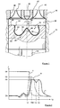
- the figure 1 illustrates, in local partial section, a direct injection internal combustion engine with auto-ignition operating with a low-temperature combustion mode.
- This engine is preferably diesel type but this does not in any way exclude other types of engine, such as those running on gasoline or a gaseous fuel (CNG, LPG, ..).
- This engine comprises at least one cylinder 10 inside which slides a piston 12 in a reciprocating movement under the effect of a rod 14 connected to a crankshaft (not shown), and a cylinder head 16 closing the top of the cylinder .
- the top of the piston comprises a concave bowl 18 which is delimited by the upper face 20 of the piston, a lateral surface 22 connected to the face 20 by a fillet 24 and a bowl bottom 26.
- a stud 28, projecting direction of the breech 16 is housed inside this bowl.
- This nipple, frustoconical general shape, is located substantially in the center of this bowl.
- this rounded top 30 of this nipple continues towards the bowl bottom 26 by a substantially rectilinear inclined flank 32, then by a curvilinear portion 34 connecting the flank 32 to the bowl bottom 26 and to the lateral surface 22.
- the different walls of this bowl are covered by a thermally insulating coating 36 which makes it possible to minimize thermal losses through these walls.
- this coating is of the ceramic type and in particular of the group of silicon nitrides. For this, the remainder of the description will mention, only as an illustrative example, ceramic coating for this bowl.
- a combustion chamber 38 is formed in this cylinder being delimited by the portion of the yoke 16 facing the piston 12, the inner peripheral surface of the cylinder 10, the upper face 20 of the piston 10, and the covered bowl walls. by the ceramic coating 36.
- the cylinder head 16 carries at least one intake means with an intake valve 40 and an intake manifold 42, and at least one exhaust means with an exhaust valve 44 and an exhaust manifold 46.
- Fuel injection means are arranged in the cylinder head 16 so as to introduce fuel into the combustion chamber 38.
- These means comprise a fuel injector 48, preferably a multi-jet injector, which comprises at least one fuel injector. near its nose a multiplicity of orifices through which is sprayed the fuel in the combustion chamber in the form of jets 50.
- the axis of the injector is placed coaxially with the pin axis so that the fuel jets are introduced into the bowl.
- the bowl, the nipple and the injector are placed coaxially with each other.
- FIG 2 shows curves illustrating the energy release (J) as a function of the crankshaft angle (° V) for a motor of the prior art (A), in dash line, without multiple fuel injection and comprising a piston with a bowl coated with a ceramic coating, for another engine of the prior art (B), dotted line, without multiple fuel injection and having a piston with a bowl without a ceramic coating, and for a motor using the method according to the invention (I), in solid line.
- fuel is introduced, in a single main injection, into the combustion chamber by the injector 48 at a crankshaft angle V1 close to the High compression point of this engine (PMH) and before this PMH. More particularly, this fuel is introduced into the bowl 18 coated with a ceramic coating to mix with the fluids (air and EGR) contained therein.
- This fuel makes it possible to produce a fuel mixture which is arranged to self-ignite under the effect of compression by the piston.
- This combustion makes it possible to generate a release of energy which increases suddenly of the energy release Dn, resulting from the compression phase of the engine, to arrive at a maximum clearance D1 before the TDC of the engine.
- the fuel is introduced, as previously described, inside the bowl 18 devoid of ceramic coating to achieve a fuel mixture.
- the energy release increases from the point Dn to arrive at a maximum clearance D2 in the vicinity of the engine PMH which is lower than that of the maximum clearance of the curve A.
- This release of energy results in lower combustion noise levels than curve A, but results in high HC emissions.
- close multiple injection strategies makes it possible to modulate this energy release in order to limit the combustion noise to acceptable levels.
- the combination of a combustion chamber with a bowl having an associated ceramic coating and these close multiple injection strategies also makes it possible to improve the compromise HC / CO / noise for engines operating according to the diesel combustion mode. CTA.
- Curve I of the figure 2 illustrates the method according to the invention with the energy releases corresponding to the total amount of fuel that is divided into two successive fuel injections equivalent to the total amount of fuel engines of the prior art.
- a first quantity of fuel is injected at the crankshaft angle V1 and then a second quantity of this fuel is injected at the crankshaft angle V2 very close to the initial injection of fuel, preferably within a time corresponding to an angle crankshaft rotation between 1 ° and 10 ° between the end of the previous injection and the beginning of this second injection.
- the first fuel injection makes it possible to obtain, at TDC, a combustion of the fuel mixture with a release of energy D2 that is lower than the energy release D1 of the engine of the prior art (reduction of energy release of the fuel).
- This energy release D2 decreases to the crankshaft angle V2 where the second quantity of fuel is injected into the combustion chamber.
- This second quantity of fuel which is here substantially identical to the first, makes it possible to achieve at the crankshaft angle V3 combustion of the fuel mixture with a release of energy which is comparable to that of the combustion of the fuel mixture of the first injection. It can also be envisaged to achieve a multiplicity of fuel injections that is greater than two injections.
- the total amount of fuel to be injected is performed according to successive fuel injections brought together with substantially identical quantities of fuel to each other until the desired injection of the total quantity of fuel equivalent to the fuel is obtained.
- motor of the prior art
- These quantities of fuel to be injected successively can also be different from each other, such as increasing or decreasing amounts with respect to each other until the total amount of fuel to be injected into the combustion chamber is obtained.
- these amounts can be between 5% and 40% of the fuel quantity of the previous injection.
Landscapes
- Engineering & Computer Science (AREA)
- Chemical & Material Sciences (AREA)
- Combustion & Propulsion (AREA)
- Mechanical Engineering (AREA)
- General Engineering & Computer Science (AREA)
- Combustion Methods Of Internal-Combustion Engines (AREA)
- Fuel-Injection Apparatus (AREA)
- Electrical Control Of Air Or Fuel Supplied To Internal-Combustion Engine (AREA)
Abstract
La présente invention concerne un procédé d'injection de carburant dans un moteur à combustion interne à injection directe, notamment de type Diesel, comportant un cylindre (10) fermé par une culasse (16), un piston (12) comportant un bol (18), et un injecteur de carburant (48).
Selon l'invention, le procédé consiste à introduire le carburant dans le bol revêtu d'un revêtement thermiquement isolant en au moins deux injections successives rapprochées de manière à réaliser une combustion à basse température du mélange carburé.
Description
- La présente invention se rapporte à un procédé d'injection de carburant dans un moteur à combustion interne à auto-inflammation à injection directe, notamment de type Diesel.
- Elle concerne plus particulièrement les moteurs de type Diesel fonctionnant en combustion à basse température du mélange carburé, plus communément connue sous le terme de combustion LTC (Low Temperature Combustion).
Ce type de combustion LTC a notamment pour avantage de limiter la production de polluants résultant de la combustion et en particulier de limiter la production d'oxydes d'azote (NOx) et de particules.
Cette combustion est généralement réalisée par l'utilisation d'une grande quantité de gaz d'échappement recirculés (EGR) à l'admission du moteur pour abaisser les températures de combustion permettant de réduire les émissions de NOx. En outre, l'emploi d'un fort pré-mélange entre l'air et le carburant a pour effet de réaliser un mélange relativement homogène avant la combustion permettant ainsi de limiter la production de particules. - Cependant, ce type de combustion a pour inconvénient majeur de produire des niveaux d'émissions de HC élevés qui sont rejetés à l'échappement du moteur. Cette production de HC est liée essentiellement aux basses températures de combustion, qui ne permettent pas l'oxydation totale des HC en CO puis en CO2.
- Comme cela est déjà décrit dans la demande de brevet
CN 1 434 193 , il est connu un tel moteur avec un cylindre à l'intérieur duquel coulisse, en un mouvement rectiligne alternatif, un piston portant un bol creux. Une chambre de combustion d'un mélange carburé est ainsi délimitée par la paroi du cylindre, la face de la culasse en vis du piston, la face supérieure de ce piston et les parois du bol. - Tel que cela est mieux explicité dans le document précité, il est prévu de minimiser les pertes thermiques (pertes de chaleur générée lors de la combustion de ce mélange carburé) à travers les parois de la chambre de combustion du moteur. Pour cela, les surfaces du bol sont couvertes au moins en partie par un revêtement isolant thermiquement, par exemple de type céramique, caractérisé notamment par une conductivité thermique très faible.
De ce fait, ce revêtement limite la perte de chaleur générée lors de la combustion du mélange carburé, ce qui permet de maintenir des températures de combustion élevées. Ces niveaux élevés de températures permettent ainsi de favoriser une meilleure oxydation des hydrocarbures imbrûlés (HC) et des monoxydes de carbone (CO). De plus, l'utilisation d'un tel revêtement entraîne une élévation des températures des parois de la chambre de combustion, ce qui a pour effet de limiter la formation de films liquides de carburant qui se forment notamment sur la surface du piston. En effet, ces films liquides de carburant sont une source non négligeable de production de HC, en particulier dans le type de combustion LTC. - Cette augmentation des températures entraîne cependant des inconvénients néfastes à la combustion, comme une réduction du délai d'auto-inflammation du mélange carburé et une augmentation de la vitesse de combustion. Ces vitesses de combustion excessives, qui entraînent généralement des pics de dégagement d'énergie élevés, sont pénalisantes car elles sont associées à des niveaux élevés de bruit de combustion (ou bruit moteur).
- La présente invention se propose de remédier aux inconvénients précités grâce à un procédé d'injection de carburant qui permet de réduire les niveaux de bruit de combustion.
- A cet effet, l'invention concerne un procédé d'injection de carburant dans un moteur à combustion interne à injection directe, notamment de type Diesel, comportant un cylindre fermé par une culasse, un piston comportant un bol, et un injecteur de carburant, caractérisé en ce qu'il consiste à introduire le carburant dans le bol revêtu d'un revêtement thermiquement isolant en au moins deux injections successives rapprochées de manière à réaliser une combustion à basse température du mélange carburé.
- Le procédé peut consister à introduire le carburant en des injections successives avec un délai correspondant à un angle de rotation de vilebrequin compris entre 1° et 10° entre la fin d'une injection et le début de l'injection suivante.
- Le procédé peut consister à introduire le carburant en des injections successives de quantité de carburant égale entre elles.
- Le procédé peut consister à introduire le carburant en des injections successives de quantité de carburant différente entre elles.
- Le procédé peut consister à introduire le carburant en des injections successives de quantité de carburant croissante entre elles.
- Le procédé peut consister à introduire le carburant en des injections successives de quantité de carburant décroissante entre elles.
- Le procédé peut consister à introduire le carburant en des injections successives de quantité de carburant comprise entre 5% et 50% de la quantité globale du carburant.
- Les autres caractéristiques et avantages de l'invention vont apparaître à la lecture de la description qui va suivre, donnée à titre uniquement illustratif et non limitatif, et à laquelle sont annexées :
- la
figure 1 qui montre une vue locale d'une partie d'un moteur à combustion interne utilisant le procédé selon l'invention et - la
figure 2 qui montre des courbes illustrant le dégagement d'énergie (J) en fonction de l'angle du vilebrequin (°V) pour des moteurs de l'art antérieur et pour un moteur utilisant le procédé selon l'invention. - La
figure 1 illustre, en coupe partielle locale, un moteur à combustion interne à injection directe à autoallumage fonctionnant avec un mode de combustion à basse température. Ce moteur est préférentiellement de type Diesel mais cela n'écarte en aucune manière les autres types de moteur, comme ceux fonctionnant avec de l'essence ou un carburant gazeux (GNV, GPL,..). - Ce moteur comprend au moins un cylindre 10 à l'intérieur duquel coulisse un piston 12 en un mouvement translatif alternatif sous l'effet d'une bielle 14 raccordée à un vilebrequin (non représenté), et une culasse 16 venant fermer le haut du cylindre.
Le haut du piston comprend un bol concave 18 qui est délimité par la face supérieure 20 du piston, une surface latérale 22 raccordée à la face 20 par un congé 24 et un fond de bol 26. De manière préférentielle, un téton 28, saillant en direction de la culasse 16, est logé l'intérieur de ce bol. Ce téton, de forme générale tronconique, est situé sensiblement au centre de ce bol. Le sommet arrondi 30 de ce téton se poursuit, en direction du fond de bol 26 par un flanc incliné 32 sensiblement rectiligne, puis par une partie curviligne 34 venant raccorder le flanc 32 au fond de bol 26 et à la surface latérale 22.
Les différentes parois de ce bol sont couvertes par un revêtement 36 isolant thermiquement permettant de minimiser les pertes thermiques au travers de ces parois.
Avantageusement, ce revêtement est du type céramique et notamment du groupe des nitrures de silicium. Pour cela, la suite de la description fera mention, uniquement à titre d'exemple illustratif, de revêtement céramique pour ce bol. - Ainsi, une chambre de combustion 38 est formée dans ce cylindre en étant délimitée par la portion de la culasse 16 en regard du piston 12, la surface périphérique interne du cylindre 10, la face supérieure 20 du piston 10, et les parois de bol couvertes par le revêtement céramique 36.
- La culasse 16 porte au moins un moyen d'admission avec une soupape d'admission 40 et une tubulure d'admission 42, et au moins un moyen d'échappement avec une soupape d'échappement 44 et une tubulure d'échappement 46.
Des moyens d'injection de carburant sont disposés dans la culasse 16 de manière à introduire du carburant à l'intérieur de la chambre de combustion 38. Ces moyens comportent un injecteur de carburant 48, de préférence un injecteur multi-jets, qui comprend au voisinage de son nez une multiplicité d'orifices à travers desquels est pulvérisé le carburant dans la chambre de combustion sous forme de jets 50.
Avantageusement, l'axe de l'injecteur est placé de manière coaxiale à l'axe du téton de manière à ce que les jets de carburant soient introduits à l'intérieur du bol. Ainsi, le bol, le téton et l'injecteur sont placés coaxialement les uns par rapport aux autres. - On se rapporte maintenant à la
figure 2 qui montre des courbes illustrant le dégagement d'énergie (J) en fonction de l'angle du vilebrequin (°V) pour un moteur de l'art antérieur (A), en trait tiret, sans injection multiple de carburant et comportant un piston avec un bol revêtu d'un revêtement céramique, pour un autre moteur de l'art antérieur (B), en trait pointillé, sans injection multiple de carburant et comportant un piston avec un bol dépourvu de revêtement céramique, et pour un moteur utilisant le procédé selon l'invention (I), en trait fort. - Ainsi, pour le moteur de l'art antérieur avec le dégagement d'énergie de la courbe A, du carburant est introduit, en une seule injection principale, dans la chambre de combustion par l'injecteur 48 à un angle de vilebrequin V1 voisin du Point Mort Haut compression de ce moteur (PMH) et avant ce PMH. Plus particulièrement, ce carburant est introduit à l'intérieur du bol 18 revêtu d'un revêtement céramique pour se mélanger avec les fluides (air et EGR) qui y sont contenus. Ce carburant permet de réaliser un mélange carburé qui est disposé à s'auto-enflammer sous l'effet de la compression par le piston. Cette combustion permet de générer un dégagement d'énergie qui s'accroît brutalement du dégagement d'énergie Dn, résultant de la phase de compression du moteur, pour arriver à un dégagement maximal D1 avant le PMH du moteur.
Comme déjà mentionné plus haut, un tel dégagement important d'énergie entraîne notamment une génération de niveaux élevés de bruit de combustion dans la chambre de combustion. En effet, l'utilisation d'un bol revêtu d'un revêtement céramique augmente la vitesse de combustion du mélange carburé en entraînant une augmentation du dégagement d'énergie ainsi que des niveaux de bruit. - Pour le dégagement d'énergie selon un autre moteur de l'art antérieur de la courbe B, le carburant est introduit, comme précédemment décrit, à l'intérieur du bol 18 dépourvu de revêtement céramique pour réaliser un mélange carburé. Lors de l'auto inflammation de ce mélange carburé, le dégagement d'énergie augmente du point Dn pour arriver à un dégagement maximal D2 au voisinage du PMH du moteur qui est inférieur à celui du dégagement maximale de la courbe A.
Ce dégagement d'énergie entraîne une production de niveaux de bruit de combustion moins élevés que celui de la courbe A mais engendre des émissions élevées de HC. - Afin de palier ce problème, l'utilisation des stratégies d'injection multiples rapprochées selon l'invention permet de moduler ce dégagement d'énergie afin de limiter le bruit de combustion à des niveaux acceptables.
De plus, la combinaison d'une chambre de combustion avec un bol comportant un revêtement en céramique associée et ces stratégies d'injection multiples rapprochées permet également d'améliorer le compromis HC/CO/bruit pour des moteurs fonctionnant selon le mode de combustion Diesel LTC. - Plus précisément, il est prévu d'adopter, pour le moteur utilisant le procédé selon l'invention (courbe I), une stratégie d'injection avec au moins deux injections successives rapprochées de carburant à partir de l'angle de vilebrequin V1.
- La courbe I de la
figure 2 illustre le procédé selon l'invention avec les dégagements d'énergie correspondant à la quantité globale de carburant qui est partagée en deux injections successives de carburant équivalentes à la quantité globale de carburant des moteurs de l'art antérieur. Une première quantité de carburant est injectée à l'angle de vilebrequin V1 puis une seconde quantité de ce carburant est injectée à l'angle de vilebrequin V2 de manière très rapprochée de l'injection initiale de carburant, préférentiellement dans un délai correspondant à un angle de rotation de vilebrequin compris entre 1° et 10° entre la fin de l'injection précédente et le début de cette deuxième injection.
Ainsi, la première injection de carburant permet d'obtenir, au PMH, une combustion du mélange carburé avec un dégagement d'énergie D2 inférieur au dégagement d'énergie D1 du moteur de l'art antérieur (réduction de dégagement d'énergie de l'ordre du tiers). Ce dégagement d'énergie D2 diminue jusqu'à l'angle de vilebrequin V2 où la deuxième quantité de carburant est injectée dans la chambre de combustion. Cette deuxième quantité de carburant, qui est ici sensiblement identique à la première, permet de réaliser à l'angle de vilebrequin V3 une combustion du mélange carburé avec un dégagement d'énergie qui est comparable à celui de la combustion du mélange carburé de la première injection.
Il peut aussi être envisagé de réaliser une multiplicité d'injections de carburant qui soit supérieure à deux injections. - Dans ce cas, il peut être prévu que la quantité totale de carburant à injecter se réalise selon des injections de carburant successives rapprochées avec des quantités de carburant sensiblement identiques entre elles jusqu'à obtenir l'injection souhaitée de la quantité totale de carburant équivalente au moteur de l'art antérieur.
- Ces quantités de carburant à injecter successivement peuvent être également différentes entre elles, telles que des quantités croissantes ou décroissantes les unes par rapport aux autres entre elles jusqu'à l'obtention de la quantité globale de carburant à injecter dans la chambre de combustion.
- Avantageusement dans le cas de quantités décroissantes, ces quantités peuvent être comprise entre 5% et 40% de la quantité de carburant de l'injection précédente.
A titre d'exemple, il peut être envisagé, pour trois injections successives, d'injecter 50% de la quantité globale lors d'une première injection à l'angle V1 avant le PMH puis 30% de cette quantité globale après un angle de rotation de vilebrequin de 5° à l'angle V2 et, lors de la troisième injection, à injecter la quantité restante de carburant (soit 20% de la quantité globale) après un angle de rotation de vilebrequin de 5° suivant la deuxième injection et avant le PMB. - Ces injections successives peuvent être régulièrement reparties entre l'angle V1 et le PMB et leur nombre peut être différents avant et après le PMH.
- Ces injections multiples rapprochées de carburant permettent de pouvoir moduler les pics de dégagement d'énergie et donc les bruits de combustion tout en réduisant les émissions de HC et en produisant une faible quantité de NOx, notamment sur les points de fonctionnement du moteur les moins chargés.
- La présente invention n'est pas limitée à l'exemple décrit mais englobe toutes variantes et tous équivalents couverts par la présente invention.
Claims (7)
- Procédé d'injection de carburant dans un moteur à combustion interne à injection directe, notamment de type Diesel, comportant un cylindre (10) fermé par une culasse (16), un piston (12) comportant un bol (18), et un injecteur de carburant (48), caractérisé en ce qu'il consiste à introduire le carburant dans le bol revêtu d'un revêtement thermiquement isolant en au moins deux injections successives rapprochées de manière à réaliser une combustion à basse température du mélange carburé.
- Procédé d'injection de carburant selon la revendication 1, caractérisé en ce qu'il consiste à introduire le carburant en des injections successives avec un délai correspondant à un angle de rotation de vilebrequin compris entre 1° et 10° entre la fin d'une injection et le début de l'injection suivante.
- Procédé d'injection de carburant selon la revendication 1 ou 2, caractérisé en ce qu'il consiste à introduire le carburant en des injections successives de quantité de carburant égale entre elles.
- Procédé d'injection de carburant selon la revendication 1 ou 2, caractérisé en ce qu'il consiste à introduire le carburant en des injections successives de quantité de carburant différente entre elles.
- Procédé d'injection de carburant selon la revendication 4, caractérisé en ce qu'il consiste à introduire le carburant en des injections successives de quantité de carburant croissante entre elles.
- Procédé d'injection de carburant selon la revendication 4, caractérisé en ce qu'il consiste à introduire le carburant en des injections successives de quantité de carburant décroissante entre elles.
- Procédé d'injection de carburant selon l'une des revendications précédentes, caractérisé en ce qu'il consiste à introduire le carburant en des injections successives de quantité de carburant comprise entre 5% et 50% de la quantité globale du carburant.
Applications Claiming Priority (1)
| Application Number | Priority Date | Filing Date | Title |
|---|---|---|---|
| FR0902660A FR2946393A1 (fr) | 2009-06-03 | 2009-06-03 | Procede d'injection de carburant dans un moteur a combustion interne a auto-inflammation a injection directe. |
Publications (1)
| Publication Number | Publication Date |
|---|---|
| EP2261491A1 true EP2261491A1 (fr) | 2010-12-15 |
Family
ID=41506525
Family Applications (1)
| Application Number | Title | Priority Date | Filing Date |
|---|---|---|---|
| EP10290280A Withdrawn EP2261491A1 (fr) | 2009-06-03 | 2010-05-27 | Procédé d'injection de carburant dans un moteur à combustion interne à auto-inflammation à injection directe |
Country Status (4)
| Country | Link |
|---|---|
| US (1) | US8505513B2 (fr) |
| EP (1) | EP2261491A1 (fr) |
| JP (1) | JP2010281322A (fr) |
| FR (1) | FR2946393A1 (fr) |
Families Citing this family (8)
| Publication number | Priority date | Publication date | Assignee | Title |
|---|---|---|---|---|
| FR2946393A1 (fr) * | 2009-06-03 | 2010-12-10 | Inst Francais Du Petrole | Procede d'injection de carburant dans un moteur a combustion interne a auto-inflammation a injection directe. |
| WO2015029117A1 (fr) * | 2013-08-26 | 2015-03-05 | 日本碍子株式会社 | Moteur à combustion interne |
| JP6526456B2 (ja) * | 2015-03-24 | 2019-06-05 | 株式会社豊田中央研究所 | ディーゼルエンジン |
| US10519854B2 (en) | 2015-11-20 | 2019-12-31 | Tenneco Inc. | Thermally insulated engine components and method of making using a ceramic coating |
| US10578050B2 (en) | 2015-11-20 | 2020-03-03 | Tenneco Inc. | Thermally insulated steel piston crown and method of making using a ceramic coating |
| SE542894C2 (en) | 2018-05-30 | 2020-08-18 | Scania Cv Ab | Diesel engine |
| CN110318859A (zh) * | 2019-06-26 | 2019-10-11 | 哈尔滨工程大学 | 一种多次喷射天然气的发动机分层快速燃烧方法 |
| CN110318900B (zh) * | 2019-06-26 | 2022-06-21 | 哈尔滨工程大学 | 一种缸内、进气岐管及预燃室混合供气的燃烧方法 |
Citations (6)
| Publication number | Priority date | Publication date | Assignee | Title |
|---|---|---|---|---|
| JPH10252476A (ja) * | 1997-03-06 | 1998-09-22 | Yanmar Diesel Engine Co Ltd | 直噴式ディーゼル機関の燃焼方法 |
| WO2001033060A1 (fr) * | 1999-10-29 | 2001-05-10 | Yanmar Diesel Engine Co., Ltd. | Moteur diesel a injection directe |
| CN1434193A (zh) | 2003-02-27 | 2003-08-06 | 上海交通大学 | 实现柴油机低排放均质燃烧的方法 |
| WO2003064831A1 (fr) * | 2002-02-01 | 2003-08-07 | Scania Cv Ab (Publ) | Moteur a combustion |
| US20050211218A1 (en) * | 2004-03-25 | 2005-09-29 | Zhengbai Liu | Control strategy for HCCI-CD combustion in a diesel engine using two fuel injection phases |
| DE102005051740A1 (de) * | 2004-12-04 | 2006-06-08 | Daimlerchrysler Ag | Brennraum einer selbstzündenden Brennkraftmaschine |
Family Cites Families (6)
| Publication number | Priority date | Publication date | Assignee | Title |
|---|---|---|---|---|
| US3358349A (en) * | 1964-08-05 | 1967-12-19 | Darlite Corp | Method of explosion cladding irregular aluminum objects |
| JP4209317B2 (ja) * | 2003-12-18 | 2009-01-14 | 三菱重工業株式会社 | 内燃機関の排気浄化装置 |
| FR2946393A1 (fr) * | 2009-06-03 | 2010-12-10 | Inst Francais Du Petrole | Procede d'injection de carburant dans un moteur a combustion interne a auto-inflammation a injection directe. |
| JP5045773B2 (ja) * | 2010-03-12 | 2012-10-10 | トヨタ自動車株式会社 | 燃料噴射制御装置 |
| US8051829B2 (en) * | 2010-10-08 | 2011-11-08 | Ford Global Technologies, Llc | Method for controlling low temperature combustion |
| WO2012125961A1 (fr) * | 2011-03-17 | 2012-09-20 | Cummins Intellectual Property, Inc. | Piston pour moteur à combustion interne |
-
2009
- 2009-06-03 FR FR0902660A patent/FR2946393A1/fr not_active Withdrawn
-
2010
- 2010-05-27 EP EP10290280A patent/EP2261491A1/fr not_active Withdrawn
- 2010-06-03 JP JP2010127862A patent/JP2010281322A/ja not_active Withdrawn
- 2010-06-03 US US12/793,067 patent/US8505513B2/en not_active Expired - Fee Related
Patent Citations (6)
| Publication number | Priority date | Publication date | Assignee | Title |
|---|---|---|---|---|
| JPH10252476A (ja) * | 1997-03-06 | 1998-09-22 | Yanmar Diesel Engine Co Ltd | 直噴式ディーゼル機関の燃焼方法 |
| WO2001033060A1 (fr) * | 1999-10-29 | 2001-05-10 | Yanmar Diesel Engine Co., Ltd. | Moteur diesel a injection directe |
| WO2003064831A1 (fr) * | 2002-02-01 | 2003-08-07 | Scania Cv Ab (Publ) | Moteur a combustion |
| CN1434193A (zh) | 2003-02-27 | 2003-08-06 | 上海交通大学 | 实现柴油机低排放均质燃烧的方法 |
| US20050211218A1 (en) * | 2004-03-25 | 2005-09-29 | Zhengbai Liu | Control strategy for HCCI-CD combustion in a diesel engine using two fuel injection phases |
| DE102005051740A1 (de) * | 2004-12-04 | 2006-06-08 | Daimlerchrysler Ag | Brennraum einer selbstzündenden Brennkraftmaschine |
Also Published As
| Publication number | Publication date |
|---|---|
| US20100307450A1 (en) | 2010-12-09 |
| FR2946393A1 (fr) | 2010-12-10 |
| US8505513B2 (en) | 2013-08-13 |
| JP2010281322A (ja) | 2010-12-16 |
Similar Documents
| Publication | Publication Date | Title |
|---|---|---|
| EP1217186B1 (fr) | Moteur à injection directe pourvu d'un faible angle de nappe et procédés permettant d'utiliser un tel moteur | |
| FR2946393A1 (fr) | Procede d'injection de carburant dans un moteur a combustion interne a auto-inflammation a injection directe. | |
| EP3099908B1 (fr) | Moteur à combustion à injection directe de combustible et plus particulièrement moteur à allumage par compression avec faible taux de compression | |
| FR3019589B1 (fr) | Procede d'injection de combustible dans la chambre de combustion d'un moteur a combustion interne fonctionnant en monocarburation ou en multicarburation | |
| EP3060774B1 (fr) | Moteur à combustion à injection directe de combustible à allumage par compression et procédé d'injection de combustible pour un tel moteur | |
| Lee et al. | Operating strategy for gasoline/diesel dual-fuel premixed compression ignition in a light-duty diesel engine | |
| FR2864578A1 (fr) | Moteur deux temps a injection directe | |
| EP1344914B1 (fr) | Moteur à combustion interne avec dispositif d'injection de carburant | |
| EP1801398B1 (fr) | Procédé d'injection de carburant pour moteur à combustion interne, notamment à injection directe, comportant un piston muni d'un bol avec un téton | |
| FR2818325A1 (fr) | Moteur a injection directe pourvu d'un faible angle de nappe et procedes permettant d'utiliser un tel moteur | |
| EP1247013B1 (fr) | Moteur a combustion interne a injection directe a soupapes commandees | |
| FR2960261A1 (fr) | Procede de controle de la combustion d'un moteur a combustion interne bicarburation, notamment pour vehicule automobile | |
| EP1861596B1 (fr) | Moteur a combustion interne, notamment a injection directe, avec un piston muni d'un bol comprenant un teton | |
| FR3071879A1 (fr) | Moteur a combustion interne a deux soupapes | |
| FR3071878B1 (fr) | Chambre de combustion de forme elliptique | |
| FR2818324A1 (fr) | Moteur a injection directe, pourvu d'un injecteur a faible angle de nappe | |
| WO2015058906A1 (fr) | Moteur à combustion interne à injection directe à allumage par compression et procédé d'injection de combustible dans la chambre de combustion de ce moteur | |
| FR2925114A1 (fr) | Moteur a combustion interne a autoinflammation avec stratification de temperature du melange carbure et procede pour realiser un tel melange | |
| FR2878906A1 (fr) | Moteur a injection directe de carburant avec un piston comportant un bol presentant une paroi laterale inclinee | |
| FR3072129A1 (fr) | Procede de gestion du fonctionnement d'un moteur a allumage commande a injection directe | |
| FR2910539A1 (fr) | Agencement de l'element de chauffage d'une bougie de prechauffage dans une chambre de combustion | |
| FR2942639A1 (fr) | Procede de controle de l'injection d'un carburant dans un moteur a combustion interne a injection directe | |
| FR2918114A1 (fr) | Moteur a combustion interne. | |
| FR2925115A1 (fr) | Moteur a combustion interne a injection directe de carburant et procede pour realiser un melange carbure utilise pour ce moteur | |
| FR2876744A1 (fr) | Procede de commande d'un moteur comportant une injection de carburant en deux phases |
Legal Events
| Date | Code | Title | Description |
|---|---|---|---|
| PUAI | Public reference made under article 153(3) epc to a published international application that has entered the european phase |
Free format text: ORIGINAL CODE: 0009012 |
|
| AK | Designated contracting states |
Kind code of ref document: A1 Designated state(s): AL AT BE BG CH CY CZ DE DK EE ES FI FR GB GR HR HU IE IS IT LI LT LU LV MC MK MT NL NO PL PT RO SE SI SK SM TR |
|
| AX | Request for extension of the european patent |
Extension state: BA ME RS |
|
| 17P | Request for examination filed |
Effective date: 20110615 |
|
| 17Q | First examination report despatched |
Effective date: 20140711 |
|
| STAA | Information on the status of an ep patent application or granted ep patent |
Free format text: STATUS: THE APPLICATION IS DEEMED TO BE WITHDRAWN |
|
| 18D | Application deemed to be withdrawn |
Effective date: 20141122 |