EP2261481A1 - Turbocharged engine for a vehicle, vehicle equipped therewith, and corresponding method - Google Patents
Turbocharged engine for a vehicle, vehicle equipped therewith, and corresponding method Download PDFInfo
- Publication number
- EP2261481A1 EP2261481A1 EP10005277A EP10005277A EP2261481A1 EP 2261481 A1 EP2261481 A1 EP 2261481A1 EP 10005277 A EP10005277 A EP 10005277A EP 10005277 A EP10005277 A EP 10005277A EP 2261481 A1 EP2261481 A1 EP 2261481A1
- Authority
- EP
- European Patent Office
- Prior art keywords
- exhaust
- sized turbocharger
- vehicle
- gas purification
- purification device
- Prior art date
- Legal status (The legal status is an assumption and is not a legal conclusion. Google has not performed a legal analysis and makes no representation as to the accuracy of the status listed.)
- Granted
Links
- 238000000034 method Methods 0.000 title claims description 11
- 238000000746 purification Methods 0.000 claims abstract description 91
- 239000003054 catalyst Substances 0.000 claims description 7
- 238000007254 oxidation reaction Methods 0.000 claims description 7
- 238000011144 upstream manufacturing Methods 0.000 claims description 3
- 239000000498 cooling water Substances 0.000 description 16
- 239000002699 waste material Substances 0.000 description 6
- 230000001105 regulatory effect Effects 0.000 description 5
- 230000003213 activating effect Effects 0.000 description 3
- 238000005452 bending Methods 0.000 description 2
- 238000004378 air conditioning Methods 0.000 description 1
- 230000008602 contraction Effects 0.000 description 1
- 238000001816 cooling Methods 0.000 description 1
- 230000001419 dependent effect Effects 0.000 description 1
- 238000010586 diagram Methods 0.000 description 1
- 230000000694 effects Effects 0.000 description 1
- 239000000446 fuel Substances 0.000 description 1
- 230000001050 lubricating effect Effects 0.000 description 1
- 238000012986 modification Methods 0.000 description 1
- 230000004048 modification Effects 0.000 description 1
- 238000005192 partition Methods 0.000 description 1
- 230000008929 regeneration Effects 0.000 description 1
- 238000011069 regeneration method Methods 0.000 description 1
- XLYOFNOQVPJJNP-UHFFFAOYSA-N water Substances O XLYOFNOQVPJJNP-UHFFFAOYSA-N 0.000 description 1
Images



Classifications
-
- B—PERFORMING OPERATIONS; TRANSPORTING
- B60—VEHICLES IN GENERAL
- B60K—ARRANGEMENT OR MOUNTING OF PROPULSION UNITS OR OF TRANSMISSIONS IN VEHICLES; ARRANGEMENT OR MOUNTING OF PLURAL DIVERSE PRIME-MOVERS IN VEHICLES; AUXILIARY DRIVES FOR VEHICLES; INSTRUMENTATION OR DASHBOARDS FOR VEHICLES; ARRANGEMENTS IN CONNECTION WITH COOLING, AIR INTAKE, GAS EXHAUST OR FUEL SUPPLY OF PROPULSION UNITS IN VEHICLES
- B60K13/00—Arrangement in connection with combustion air intake or gas exhaust of propulsion units
- B60K13/04—Arrangement in connection with combustion air intake or gas exhaust of propulsion units concerning exhaust
-
- F—MECHANICAL ENGINEERING; LIGHTING; HEATING; WEAPONS; BLASTING
- F02—COMBUSTION ENGINES; HOT-GAS OR COMBUSTION-PRODUCT ENGINE PLANTS
- F02B—INTERNAL-COMBUSTION PISTON ENGINES; COMBUSTION ENGINES IN GENERAL
- F02B37/00—Engines characterised by provision of pumps driven at least for part of the time by exhaust
- F02B37/004—Engines characterised by provision of pumps driven at least for part of the time by exhaust with exhaust drives arranged in series
-
- F—MECHANICAL ENGINEERING; LIGHTING; HEATING; WEAPONS; BLASTING
- F02—COMBUSTION ENGINES; HOT-GAS OR COMBUSTION-PRODUCT ENGINE PLANTS
- F02B—INTERNAL-COMBUSTION PISTON ENGINES; COMBUSTION ENGINES IN GENERAL
- F02B37/00—Engines characterised by provision of pumps driven at least for part of the time by exhaust
- F02B37/013—Engines characterised by provision of pumps driven at least for part of the time by exhaust with exhaust-driven pumps arranged in series
-
- Y—GENERAL TAGGING OF NEW TECHNOLOGICAL DEVELOPMENTS; GENERAL TAGGING OF CROSS-SECTIONAL TECHNOLOGIES SPANNING OVER SEVERAL SECTIONS OF THE IPC; TECHNICAL SUBJECTS COVERED BY FORMER USPC CROSS-REFERENCE ART COLLECTIONS [XRACs] AND DIGESTS
- Y02—TECHNOLOGIES OR APPLICATIONS FOR MITIGATION OR ADAPTATION AGAINST CLIMATE CHANGE
- Y02T—CLIMATE CHANGE MITIGATION TECHNOLOGIES RELATED TO TRANSPORTATION
- Y02T10/00—Road transport of goods or passengers
- Y02T10/10—Internal combustion engine [ICE] based vehicles
- Y02T10/12—Improving ICE efficiencies
Definitions
- the present invention relates to a turbocharged engine for a vehicle.
- a turbocharged engine for a vehicle in which a small-sized turbocharger, a large-sized turbocharger, and an exhaust-gas purification device are supported at an engine body, is known.
- Japanese Patent Laid-Open Publication No. 2006-70878 discloses an engine which is arranged laterally so that its crank-shaft direction matches an axle direction of the vehicle, in which the small-sized turbocharger, the large-sized turbocharger, and a DPF (Diesel Particulate Filter) are arranged in back of the engine body in a vehicle longitudinal direction.
- the large-sized turbocharger and DPF are arranged laterally so that their respective axial lines extend in the crank-shaft direction, and arranged almost at the same height position so that they are located side by side in the axial direction on a one-side face of the engine body.
- an outlet of a turbine is directly connected to an exhaust inlet of the DPF.
- the small-sized turbocharger is arranged laterally so that its axial line extends in the crank-shaft direction, and it is located above the DPF (further above the large-sized turbocharger).
- An exhaust manifold has two exhaust outlets, and one of them is connected to a turbine of the small-sized turbocharger and the other is connected to a turbine of the large-sized turbocharger via a bypass passage, bypassing the small-sized turbocharger.
- An exhaust pipe which connects to an outlet of the turbine of the small-sized turbocharger extends upward and then bends downward toward the large-sized turbocharger, and finally connects to the above-described bypass passage.
- turbocharged engine since the both turbochargers are arranged near the engine body, the loss of exhaust energy is so small that the supercharging function improves. Further, since the DPF is directly connected to the outlet of the turbine of the large-sized turbocharger, the high-temperature exhaust gas is supplied to the DPF so that the regeneration of filter improves.
- An object of the present invention is to provide a turbocharged engine for a vehicle which can provide a properly compact arrangement of the large-sized turbocharger, small-sized turbocharger, and exhaust-gas purification device even in case the size of the exhaust-gas purification device is large.
- a turbocharged engine for a vehicle comprising a small-sized turbocharger, a turbine of which is connected to an outlet of an exhaust manifold provided on a one-side face of an engine body, a large-sized turbocharger, a turbine of which is connected to an outlet of the turbine of the small-sized turbocharger, and an exhaust-gas purification device connected to an outlet of the turbine of the large-sized turbocharger, wherein the small-sized turbocharger is arranged near one side of a crank-shaft direction (an axial direction of the crank-shaft) at the one-side face of the engine body, the large-sized turbocharger is arranged substantially above the small-sized turbocharger near the one side of the crank-shaft direction at the one-side face of the engine body so that the outlet of the turbine thereof faces substantially toward the other side of the crank-shaft direction, the exhaust-gas purification device is arranged substantially vertically, i.e.
- an axis of the exhaust-gas purification device is arranged substantially vertically or a greater dimension extends substantially vertically while a smaller dimension extends substantially horizontally, on the other side of the crank-shaft direction, which is opposite to the one side of the crank-shaft direction, relative to the small-sized turbocharger and large-sized turbocharger at the one-side face of the engine body so that an exhaust inlet thereof is located above and an exhaust outlet thereof is located below, and the exhaust inlet of the exhaust-gas purification device is connected to the outlet of the turbine of the large-sized turbocharger and the exhaust outlet of the exhaust-gas purification device is connected to an exhaust pipe.
- the both turbochargers and the exhaust-gas purification device can be arranged compactly without projecting from the both ends of the engine body greatly (ends in an axial direction of the crank-shaft). Accordingly, the flexibility of layout of the engine devices or any devices located in the engine room can improve.
- the large-sized turbocharger is arranged above the small-sized turbocharger so that the outlet of the turbine thereof faces toward the exhaust-gas purification device, the outlet of the turbine and the exhaust outlet of the exhaust-gas purification device can be connected with the shortest distance.
- the both turbochargers are arranged near the one side of the crank-shaft direction, intake and exhaust passages which connect the respective turbines or compressors of these turbochargers can be made short as well.
- the structure of the pipes can be simplified by reducing the number of flexible pipes used, and the support of these turbochargers and the exhaust-gas purification device at the engine body can be facilitated.
- a first bypass passage which introduces exhaust gas from the outlet of the exhaust manifold to the large-sized turbocharger, bypassing the small-sized turbocharger, and/or a second bypass passage which introduces exhaust gas to the exhaust-gas purification device, bypassing the large-sized turbocharger, and valves are respectively provided in the first and/or second bypass passages, the valves opening the respective bypass passages preferably when a temperature of the exhaust-gas purification device does not reach a specified active temperature capable to purify the exhaust gas.
- the small-sized turbocharger and the large-sized turbocharger are located so that the outlet of the exhaust manifold is positioned between the turbochargers, and/or a bifurcate exhaust-pipe portion extends from the outlet of the exhaust manifold so that a lower pipe-portion thereof connects to the small-sized turbocharger and an upper-pipe portion thereof connects to the large-sized turbocharger, the upper-pipe portion preferably constituting the first bypass passage.
- the length of the first bypass passage can be shortened, so that the amount of heat of the exhaust gas which may get away before the exhaust gas reaches the exhaust-gas purification device can be reduced, which should be advantageous in activating the exhaust-gas purification device quickly.
- the exhaust-gas purification device comprises a container including an oxidization catalyst preferably located above and upstream and a diesel particulate filter preferably located below and downstream.
- said exhaust-gas purification device is supported with a lower end portion thereof via a lower bracket which projects substantially toward the side from a cylinder block.
- said exhaust-gas purification device is supported with an upper end portion thereof via an upper bracket which projects substantially toward the side from a cylinder head or cylinder head cover.
- said turbochargers are supported at the cylinder head via an upstream-side exhaust pipe and/or said lower-side small-sized turbocharger is supported by a bracket which projects toward the side from the cylinder block.
- a vehicle comprising a turbocharged engine, as described above.
- a master back or brake booster of a brake device and the engine body are arranged in an engine room in front of a vehicle compartment of the vehicle, and/or the engine body is arranged laterally so that the crank-shaft direction matches an axle direction of the vehicle, the small-sized turbocharger, large-sized turbocharger and exhaust-gas purification device are located in back of the engine body in a vehicle longitudinal direction, and/or the master back is arranged behind the engine body on the side of the small-sized turbocharger and large-sized turbocharger in the crank-shaft direction.
- the engine body occupies a rather wide space inside the engine room in the axle direction of the vehicle, so it may be necessary to arrange some devices located behind the engine body so as not to extend greatly in the axle direction, avoiding any interference of these devices with the master back of the brake device.
- the both turbochargers are arranged near the one side of the crank-shaft direction at the one-side face of the engine body and the exhaust-gas purification device is arranged in the open space on the opposite side of the crank-shaft direction, it can be avoided that these devices project greatly from the both ends of the engine body in the crank-shaft direction, and the layout of the master back can be facilitated.
- a master back of a brake device and the engine body are arranged in an engine room in front of a vehicle compartment of the vehicle, and/or the engine body is arranged laterally so that the crank-shaft direction matches an axle direction of the vehicle, the small-sized turbocharger, large-sized turbocharger and exhaust-gas purification device are located in back of the engine body in a vehicle longitudinal direction, and/or the master back is arranged behind the engine body on the side of the exhaust-gas purification device in the crank-shaft direction.
- the exhaust-gas purification device is arranged vertically so that its exhaust inlet is located above and its exhaust outlet is located below, the exhaust pipe connecting to its exhaust outlet can be made easily pass through the saddle-shaped exhaust-pipe storage at the floor front portion of the vehicle, without improperly bending in the engine room, which should be advantageous in reducing the exhaust resistance.
- said exhaust pipe connecting to the exhaust outlet of the exhaust-gas purification device is stored in a saddle-shaped exhaust-pipe storage which is formed at a central position of a floor front portion of the vehicle so as to extend substantially in a vehicle longitudinal direction in such a manner that a front end thereof opens in an engine room of the vehicle.
- a method of arranging a small-sized turbocharger, a large-sized turbocharger, and an exhaust-gas purification device on a turbocharged engine for a vehicle comprising the steps of:
- the method further comprises the steps of:
- a method of arranging a turbocharged engine in a vehicle comprising the steps of:
- the method further comprises the steps of:
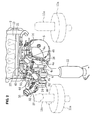
- FIG. 1 is a view of a turbocharged engine 1 for a vehicle, when viewed from a rear side in a vehicle longitudinal direction.
- An engine body 2 is arranged laterally so that its crank-shaft direction matches an axle direction of the vehicle.
- a small-sized turbocharger 3, a large-sized turbocharger 4, and an exhaust-gas purification device 5 are arranged on a one-side face of a rear side of the engine body 2 in the vehicle longitudinal direction.
- reference numeral 6 denotes a floor panel and reference numeral 7 denotes a dash panel which partitions a vehicle compartment from an engine room.
- a floor tunnel member 8 is provided at a central portion of the floor panel 6 so as to extend in the longitudinal direction, and this floor tunnel member 8 forms a saddle-shaped exhaust-pipe storage 9 at a front end of a front portion of a vehicle floor, a front end of which opens in the engine room.
- a master back or brake booster 11a of a brake device of the vehicle is preferably attached to a dash panel 7.
- the left-side master back 11a is for a vehicle with a left-side steering wheel
- the right-side master back 11 a is for a vehicle with a right-side steering wheel.
- the small-sized turbocharger 3 is arranged near one side of a crank-shaft direction at a side face of the engine body 2.
- the large-sized turbocharger 4 is arranged above the small-sized turbocharger 2 near the one side of the crank-shaft direction substantially at the side face of the engine body 2.
- These turbochargers 3, 4 are arranged substantially laterally so that their axial shafts substantially extend in the crank-shaft direction and respective outlets of their turbines 3a, 4a face substantially toward the other side of the crank-shaft direction.
- the exhaust-gas purification device 5 is arranged substantially vertically on the other side of the crank-shaft direction, which is opposite to the above-described one side of the crank-shaft direction, relative to the turbochargers 3, 4 at the one-side face of the engine body so that its exhaust inlet is located above and its exhaust outlet is located below.
- This exhaust-gas purification device 5 comprises a container, and an oxidization catalyst located above (upstream) and a DPF located below (downstream) which are contained in the container.
- an outlet pipe portion 5b of a lower side of the exhaust-gas purification device 5 is connected to a downstream-side exhaust pipe 12 which is preferably stored in the saddle-shaped exhaust-pipe storage 9.
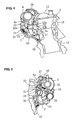
- the exhaust-gas purification device 5 is supported so that its upper end portion is supported at an upper bracket 14 which projects toward the side from a cylinder head cover 13 as shown in FIGS. 2 and 3 , and its lower end portion is supported at a lower bracket 16 which projects toward the side from a cylinder block 15 as shown in FIGS. 1 and 3 .
- a support shaft is provided at the upper bracket 14 so as to extend substantially in the crank-shaft direction, and an upper end portion of the exhaust-gas purification device 5 is supported at the support shaft.
- the exhaust-gas purification device 5 is received by the lower bracket 16 so that its lower face is fixed to the lower bracket 16. When its fixing to the lower bracket 16 is released, a lower portion of the exhaust-gas purification device 5 is allowed to rotate longitudinally around the support shaft of the upper bracket 14.
- turbochargers 3, 4 are preferably connected via intake and exhaust pipes which will be described, and as shown in FIGS. 1 and 4 , the lower-side small-sized turbocharger 3 is supported at a bracket 17 which projects toward the side from the cylinder block 15. Further, the turbochargers 3, 4 are preferably supported at a cylinder head 18 shown in FIG. 4 via an upstream-side exhaust pipe 22.
- an exhaust manifold 21 which gathers exhaust gas from exhaust ports of respective cylinders of the engine is preferably integrally formed with the engine body 2.
- the upstream-side exhaust pipe 22 is connected to an outlet of the exhaust manifold of the cylinder head 18 as shown in FIG. 4 .
- the small-sized turbocharger 3 and the large-sized turbocharger 4 are arranged below and above the exhaust-manifold outlet, respectively.
- the upstream-side exhaust pipe 22 bifurcates substantially vertically.
- An upper bifurcate portion 22a is connected to an inlet of the turbine 4a of the large-sized turbocharger 4.
- a lower bifurcate portion 22b is connected to an inlet of the turbine 3a of the small-sized turbocharger 3.
- the outlet of the turbine 3a of the small-sized turbocharger 3 and the inlet of the turbine 4 a of the large-sized turbocharger 4 are connected via a turbine connection pipe 23 so as to have the exhaust gas from the small-sized turbocharger 3 flow into the large-sized turbocharger 4.
- the turbine connection pipe 23 includes a flexible pipe 23a which can absorb the thermal expansion/contraction at its middle portion.
- the upper bifurcate portion 22a of the upstream-side exhaust pipe 22 forms a first bypass passage which bypasses the turbine 3a of the small-sized turbocharger 3 to have the exhaust gas into the large-sized turbocharger 4, and comprises a regulating valve (reference numeral 25 in FIG. 6 ) which is driven by an actuator 24 shown in FIG. 1 .
- the upper bifurcate portion 22a and the turbine connection pipe 23 gather together and are connected to the inlet of the turbine 4a of the large-sized turbocharger 4.
- a turbine downstream pipe 26 extends toward the side from the outlet of the turbine 4a of the large-sized turbocharger 4, and is connected to an inlet pipe portion 5a of the exhaust-gas purification device 5. Further, there is provided a bifurcate passage (second bypass passage) which bypasses the turbine 4a of the large-sized turbocharger 4 and introduces the exhaust gas from a connection portion of the upper bifurcate portion 22a and the turbine connection pipe 23 into the turbine downstream pipe 26.
- a waste gate valve (reference numeral 28 in FIG. 6 ), which is driven by an actuator 27 shown in FIG. 2 , is provided at this bifurcate portion.
- an intake pipe 30 which extends from an air cleaner (not illustrated) is connected to an inlet of a compressor 4b of the large-sized turbocharger 4.
- An outlet of the compressor 4b of the large-sized turbocharger 4 and an inlet of the compressor 3b of the small-sized turbocharger 3 are connected by a compressor connection pipe 31 shown in FIG. 5 to have the intake air from the large-sized turbocharger 4 flow into the small-sized turbocharger 3.
- the compressor connection pipe 31 bifurcates at its middle portion to form an intake supply pipe 32, which supplies the intake air to the engine body 2 via an intercooler (not illustrated).
- This intake supply pipe 32 has an intake cut valve (reference numeral 33 in FIG. 6 ) therein, which is driven by an actuator 35 shown in FIG. 2 and others.
- a compressor downstream pipe 34 is connected to an outlet of the compressor 3b of the small-sized turbocharger 3.
- This compressor downstream pipe 34 is connected to the intake supply pipe 32 at a position downstream of the intake cut valve 33 so as to supply the intake air to the intercooler.
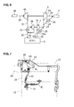
- FIG. 6 shows schematically the structure of the above-described intake and exhaust system.
- the upstream-side exhaust pipe 22 extending from the engine body 2 bifurcates at its middle portion, and one of them (lower bifurcate portion 22b) connects to the turbine 3a of the small-sized turbocharger 3 and the other (upper bifurcate portion 22a) connects to the turbine connection pipe 23 which connects the turbines of the turbochargers 3, 4.
- This upper bifurcate portion 22a constitutes the first bypass passage including the regulating valve 25.
- a second bypass passage 29 including the waste gate valve 28 extends from the turbine connection pipe 23 to the turbine downstream pipe 26 of the large-sized turbocharger 4.
- the intake pipe 30 extending from the air cleaner 36 is connected to the compressor 4b of the large-sized turbocharger 4, this compressor 4b and the compressor 3b of the small-sized turbocharger 3 are connected via the compressor connection pipe 31, and the intake cut valve 33 is provided in the intake supply pipe 32.
- the compressor downstream pipe 34 extending from the outlet of the compressor 3b of the small-sized turbocharger 3 is connected to the intake supply pipe 32 at a position downstream of the intake cut valve 33.
- the intake cut valve 33 and the waste gate valve 28 are closed, and the supercharging pressure is set at a target supercharging pressure by an opening control of the first bypass passage 22a with the regulating valve 25.
- the intake cut valve 33 and the regulating valve 25 are opened, and the supercharging pressure is set at the target supercharging pressure by an opening control of the second bypass passage 29 with the waste gate valve 28.
- the intake cut valve 33 and the waste gate valve 28 are opened, so that the exhaust gas from the exhaust manifold 21 flows into the exhaust-gas purification device 5 via the first and second bypass passages 22a, 29.
- the oxidization catalyst can be activated quickly by the high-temperature exhaust gas which is not cooled down by the turbochargers 3, 4.
- a cooling-water supply pipe 41 extends from the cylinder head 18 of the engine body 2 to a center housing 3c of the small-sized turbocharger 3, and the center housing 3c is cooled by the cooling water.
- a cooling-water supply pipe 42 which extends upward from the center housing 3c of the small-sized turbocharger 3 is connected to a center housing 4c of the large-sized turbocharger 4 (see FIGS. 1 and 8 ), and the center housing 4c is cooled by the cooling water which has passed the center housing 3c of the small-sized turbocharger 3.
- a cooling-water return pipe 43 which returns the cooling water to the cylinder block 15 extends from the center housing 4c of the large-sized turbocharger 4. As shown in FIG. 8 , this cooling-water return pipe 43 bends substantially downward once and then substantially upward, and extends substantially along a blowby-gas pipe 44 shown in FIGS. 1 and 2 on the one side of the crank-shaft direction and then extends substantially toward the other end of the crank-shaft direction and connects to the cylinder block 15.
- the blowby-gas pipe 44 for returning the blowby gas to the intake side is connected to a gas pipe 45 which projects from the cylinder head cover 13 at its one end and connected to the intake supply pipe 30 at the other end.
- an oil outlet portion 51 to take out the oil for cooling and lubricating bearings of the turbochargers 3, 4 is provided at an end portion of the cylinder head 18 on one side of the crank-shaft direction.
- the oil supply pipe 52 which extends substantially upward from the oil outlet portion 51 is connected to the upper face of the center housing 4c of the large-sized turbocharger 4 as shown in FIGS. 2 and 8 .
- An oil return pipe 53 to return the oil from the lower face of the center housing 4c to the cylinder block 15 extends substantially downward as shown in FIG. 8 , and is connected to an oil return portion 54 of the cylinder block as shown in FIG. 1 .
- an oil supply pipe 55 which extends substantially downward from the oil outlet portion 51 is connected to the upper face of the center housing 3c of the small-sized turbocharger 3 as shown in FIG. 8 .
- An oil return pipe 56 extends substantially downward from the lower face of the center housing 3c, and is connected to the oil return portion 54 of the cylinder block as shown in FIG. 1 .
- the turbochargers 3, 4 are arranged vertically near the one side of the crank-shaft direction at the one-side face of the engine body 2, and the exhaust-gas purification device 5 is arranged at the open space made on the other side of the crank-shaft direction.
- the turbochargers 3, 4 and the exhaust-gas purification device 5 can be arranged compactly without projecting from the both ends of the engine body 2 greatly. Accordingly, the flexibility of layout of the engine devices such as the air cleaner, intercooler, EGR system's pipes, battery, fuel pump or any devices located in the engine room can improve.
- the large-sized exhaust-gas purification device 5 is arranged so as not to project from the end of the engine body on the opposite side of the crank-shaft direction, any interference with devices, such as the alternator, cooling-water pump, or air-conditioning compressor, which are arranged at the opposite-side end face of the engine body can be avoided, so that the layout of these can be facilitated.
- the turbochargers 3, 4 and the exhaust-gas purification device 5 are arranged compactly without projecting from the both ends of the engine body 2 greatly, as shown in FIGS.
- the master back 11a, a master cylinder 11b, and a reserve tank 11c of the brake device can be arranged properly for a vehicle with the left-side steering wheel or a vehicle for the right-side steering wheel even in case the engine of the vehicle is mounted laterally.
- turbochargers 3, 4 are arranged vertically so as to be located below and above the outlet of the exhaust manifold, respectively, and the upstream-side exhaust pipe 22 bifurcates and the upper bifurcate portion 22a as the first bypass passage is connected to the turbine 4a of the large-sized turbocharger 4. Accordingly, the passage length of the bypass passages 22a, 29 from the exhaust-manifold outlet to the exhaust-gas purification device 5 when the regulating valve 25 and the waste gate valve 28 are opened becomes considerably short. Therefore, when the oxidization catalyst of the exhaust-gas purification device 5 has not been activated yet, the high-temperature exhaust gas can flow into the exhaust-gas purification device 5 through the bypass passages 22a, 29, which should be advantageous in activating the oxidization catalyst quickly.
- the exhaust-gas purification device 5 is arranged substantially vertically so that its exhaust outlet is located below and it is supported at the back face of the laterally- arranged engine body 2, the outlet pipe portion 5b can be connected to the downstream-side exhaust pipe 12 in the saddle-shaped exhaust-pipe storage 9 properly just with its bending rearward and then extending.
- the exhaust pipe from the exhaust-gas purification device 5 to the saddle-shaped exhaust-pipe storage 9 bends in the engine room, which should be advantageous in reducing the exhaust resistance.
Landscapes
- Engineering & Computer Science (AREA)
- Chemical & Material Sciences (AREA)
- Combustion & Propulsion (AREA)
- Mechanical Engineering (AREA)
- General Engineering & Computer Science (AREA)
- Transportation (AREA)
- Supercharger (AREA)
- Exhaust Gas After Treatment (AREA)
Abstract
Description
- The present invention relates to a turbocharged engine for a vehicle.
- A turbocharged engine for a vehicle, in which a small-sized turbocharger, a large-sized turbocharger, and an exhaust-gas purification device are supported at an engine body, is known. Japanese Patent Laid-Open Publication No.
2006-70878 - In the engine disclosed in the above-described publication, the large-sized turbocharger and DPF are arranged laterally so that their respective axial lines extend in the crank-shaft direction, and arranged almost at the same height position so that they are located side by side in the axial direction on a one-side face of the engine body. Herein, an outlet of a turbine is directly connected to an exhaust inlet of the DPF. The small-sized turbocharger is arranged laterally so that its axial line extends in the crank-shaft direction, and it is located above the DPF (further above the large-sized turbocharger).
- An exhaust manifold has two exhaust outlets, and one of them is connected to a turbine of the small-sized turbocharger and the other is connected to a turbine of the large-sized turbocharger via a bypass passage, bypassing the small-sized turbocharger. An exhaust pipe which connects to an outlet of the turbine of the small-sized turbocharger extends upward and then bends downward toward the large-sized turbocharger, and finally connects to the above-described bypass passage.
- In case of the above-described turbocharged engine, since the both turbochargers are arranged near the engine body, the loss of exhaust energy is so small that the supercharging function improves. Further, since the DPF is directly connected to the outlet of the turbine of the large-sized turbocharger, the high-temperature exhaust gas is supplied to the DPF so that the regeneration of filter improves.
- Herein, while the direct-connection arrangement of the large-sized turbocharger and the DPF, as an exhaust-gas purification device, arranged laterally side by side in the crank-shaft direction has the above-described advantages, in case the size of the exhaust-gas purification device becomes larger, the whole length of the large-sized turbocharger and the DPF in the crank-shaft direction becomes longer, so that both ends of these devices may project greatly from both ends of the engine body. This would cause difficulties in layouts of engine devices, such as a cooling-water pump or alternator, layouts of piping of an air cleaner, intercooler, EGR system and buttery and the like, and in layouts of a master back of a vehicle brake.
- An object of the present invention is to provide a turbocharged engine for a vehicle which can provide a properly compact arrangement of the large-sized turbocharger, small-sized turbocharger, and exhaust-gas purification device even in case the size of the exhaust-gas purification device is large.
- The object is solved by the features of the independent claims. Preferred embodiments of the present invention are subject of the dependent claims.
- According to the present invention, there is provided a turbocharged engine for a vehicle, comprising a small-sized turbocharger, a turbine of which is connected to an outlet of an exhaust manifold provided on a one-side face of an engine body, a large-sized turbocharger, a turbine of which is connected to an outlet of the turbine of the small-sized turbocharger, and an exhaust-gas purification device connected to an outlet of the turbine of the large-sized turbocharger, wherein the small-sized turbocharger is arranged near one side of a crank-shaft direction (an axial direction of the crank-shaft) at the one-side face of the engine body, the large-sized turbocharger is arranged substantially above the small-sized turbocharger near the one side of the crank-shaft direction at the one-side face of the engine body so that the outlet of the turbine thereof faces substantially toward the other side of the crank-shaft direction, the exhaust-gas purification device is arranged substantially vertically, i.e. an axis of the exhaust-gas purification device is arranged substantially vertically or a greater dimension extends substantially vertically while a smaller dimension extends substantially horizontally, on the other side of the crank-shaft direction, which is opposite to the one side of the crank-shaft direction, relative to the small-sized turbocharger and large-sized turbocharger at the one-side face of the engine body so that an exhaust inlet thereof is located above and an exhaust outlet thereof is located below, and the exhaust inlet of the exhaust-gas purification device is connected to the outlet of the turbine of the large-sized turbocharger and the exhaust outlet of the exhaust-gas purification device is connected to an exhaust pipe.
- According to the present invention, since the large-sized turbocharger and the small-sized turbocharger are arranged near the one side of the crank-shaft direction at the one-side face of the engine body, and the exhaust-gas purification device is arranged in an open space made on the opposite side of the crank-shaft direction, even in case the size of the exhaust-gas purification device is large, the both turbochargers and the exhaust-gas purification device can be arranged compactly without projecting from the both ends of the engine body greatly (ends in an axial direction of the crank-shaft). Accordingly, the flexibility of layout of the engine devices or any devices located in the engine room can improve.
- Further, since the large-sized turbocharger is arranged above the small-sized turbocharger so that the outlet of the turbine thereof faces toward the exhaust-gas purification device, the outlet of the turbine and the exhaust outlet of the exhaust-gas purification device can be connected with the shortest distance. Moreover, since the both turbochargers are arranged near the one side of the crank-shaft direction, intake and exhaust passages which connect the respective turbines or compressors of these turbochargers can be made short as well. Thus, not only the weight of pipes forming these passages but the amount of thermal expansion of the pipes may be properly reduced. Thereby, the structure of the pipes can be simplified by reducing the number of flexible pipes used, and the support of these turbochargers and the exhaust-gas purification device at the engine body can be facilitated.
- According to another embodiment of the present invention, there are provided a first bypass passage which introduces exhaust gas from the outlet of the exhaust manifold to the large-sized turbocharger, bypassing the small-sized turbocharger, and/or a second bypass passage which introduces exhaust gas to the exhaust-gas purification device, bypassing the large-sized turbocharger, and valves are respectively provided in the first and/or second bypass passages, the valves opening the respective bypass passages preferably when a temperature of the exhaust-gas purification device does not reach a specified active temperature capable to purify the exhaust gas. Thereby, since the both bypass passages are opened when the exhaust-gas purification device has not been activated yet, the exhaust gas from the exhaust manifold flows into the exhaust-gas purification device directly maintaining its high temperature, without being cooled down by the both turbochargers, which should be advantageous in activating the exhaust-gas purification device quickly.
- According to another embodiment of the present invention, the small-sized turbocharger and the large-sized turbocharger are located so that the outlet of the exhaust manifold is positioned between the turbochargers, and/or a bifurcate exhaust-pipe portion extends from the outlet of the exhaust manifold so that a lower pipe-portion thereof connects to the small-sized turbocharger and an upper-pipe portion thereof connects to the large-sized turbocharger, the upper-pipe portion preferably constituting the first bypass passage. Thereby, the length of the first bypass passage can be shortened, so that the amount of heat of the exhaust gas which may get away before the exhaust gas reaches the exhaust-gas purification device can be reduced, which should be advantageous in activating the exhaust-gas purification device quickly.
- Preferably, the exhaust-gas purification device comprises a container including an oxidization catalyst preferably located above and upstream and a diesel particulate filter preferably located below and downstream.
- Preferably, said exhaust-gas purification device is supported with a lower end portion thereof via a lower bracket which projects substantially toward the side from a cylinder block.
- Preferably, said exhaust-gas purification device is supported with an upper end portion thereof via an upper bracket which projects substantially toward the side from a cylinder head or cylinder head cover.
- Preferably, said turbochargers are supported at the cylinder head via an upstream-side exhaust pipe and/or said lower-side small-sized turbocharger is supported by a bracket which projects toward the side from the cylinder block.
- According to a further aspect, there is provided a vehicle comprising a turbocharged engine, as described above.
- According to an embodiment of the present invention, a master back or brake booster of a brake device and the engine body are arranged in an engine room in front of a vehicle compartment of the vehicle, and/or the engine body is arranged laterally so that the crank-shaft direction matches an axle direction of the vehicle, the small-sized turbocharger, large-sized turbocharger and exhaust-gas purification device are located in back of the engine body in a vehicle longitudinal direction, and/or the master back is arranged behind the engine body on the side of the small-sized turbocharger and large-sized turbocharger in the crank-shaft direction. In general, in case of the laterally-arranged engine, the engine body occupies a rather wide space inside the engine room in the axle direction of the vehicle, so it may be necessary to arrange some devices located behind the engine body so as not to extend greatly in the axle direction, avoiding any interference of these devices with the master back of the brake device. According to the present embodiment, however, since the both turbochargers are arranged near the one side of the crank-shaft direction at the one-side face of the engine body and the exhaust-gas purification device is arranged in the open space on the opposite side of the crank-shaft direction, it can be avoided that these devices project greatly from the both ends of the engine body in the crank-shaft direction, and the layout of the master back can be facilitated.
- According to another embodiment of the present invention, a master back of a brake device and the engine body are arranged in an engine room in front of a vehicle compartment of the vehicle, and/or the engine body is arranged laterally so that the crank-shaft direction matches an axle direction of the vehicle, the small-sized turbocharger, large-sized turbocharger and exhaust-gas purification device are located in back of the engine body in a vehicle longitudinal direction, and/or the master back is arranged behind the engine body on the side of the exhaust-gas purification device in the crank-shaft direction. Thereby, since the exhaust-gas purification device is arranged vertically so that its exhaust inlet is located above and its exhaust outlet is located below, the exhaust pipe connecting to its exhaust outlet can be made easily pass through the saddle-shaped exhaust-pipe storage at the floor front portion of the vehicle, without improperly bending in the engine room, which should be advantageous in reducing the exhaust resistance.
- Preferably, said exhaust pipe connecting to the exhaust outlet of the exhaust-gas purification device is stored in a saddle-shaped exhaust-pipe storage which is formed at a central position of a floor front portion of the vehicle so as to extend substantially in a vehicle longitudinal direction in such a manner that a front end thereof opens in an engine room of the vehicle.
- According to a further aspect, there is provided a method of arranging a small-sized turbocharger, a large-sized turbocharger, and an exhaust-gas purification device on a turbocharged engine for a vehicle, comprising the steps of:
- providing a small-sized turbocharger, a turbine of which is connected to an outlet of an exhaust manifold provided on a one-side face of an engine body;
- providing a large-sized turbocharger, a turbine of which is connected to an outlet of the turbine of said small-sized turbocharger;
- providing an exhaust-gas purification device connected to an outlet of the turbine of said large-sized turbocharger;
- arranging said small-sized turbocharger near one side of a crank-shaft direction at said one-side face of the engine body;
- arranging said large-sized turbocharger above said small-sized turbocharger near said one side of the crank-shaft direction at said one-side face of the engine body so that the outlet of the turbine thereof faces substantially toward the other side of said crank-shaft direction; and
- arranging said exhaust-gas purification device substantially vertically on the other side of the crank-shaft direction, which is opposite to said one side of the crank-shaft direction, relative to said small-sized turbocharger and large-sized turbocharger at said one-side face of the engine body so that an exhaust inlet thereof is located above and an exhaust outlet thereof is located below, and the exhaust inlet of the exhaust-gas purification device is connected to the outlet of the turbine of the large-sized turbocharger and the exhaust outlet of the exhaust-gas purification device is connected to an exhaust pipe.
- Preferably, the method further comprises the steps of:
- providing a first bypass passage which introduces exhaust gas from the outlet of the exhaust manifold to said large-sized turbocharger, bypassing said small-sized turbocharger, and/or
- providing a second bypass passage which introduces exhaust gas to said exhaust-gas purification device, bypassing said large-sized turbocharger, and
- providing valves respectively in the first and/or second bypass passages, the valves opening the respective bypass passages, preferably when a temperature of the exhaust-gas purification device does not reach a specified active temperature capable to purify the exhaust gas.
- According to a further aspect, there is provided a method of arranging a turbocharged engine in a vehicle, the turbocharged engine comprising a small-sized turbocharger, a large-sized turbocharger, and an exhaust-gas purification, the method comprising the steps of:
- arranging said engine body in an engine room in front of a vehicle compartment of the vehicle in a lateral manner so that the crank-shaft direction matches an axle direction of the vehicle, and
- arranging said small-sized turbocharger, said large-sized turbocharger and said exhaust-gas purification device in back of the engine body in a vehicle longitudinal direction.
- Preferably, the method further comprises the steps of:
- connecting an exhaust pipe to an exhaust outlet of the exhaust-gas purification device, and
- storing said exhaust pipe in a saddle-shaped exhaust-pipe storage which is formed at a central position of a floor front portion of the vehicle so as to extend substantially in a vehicle longitudinal direction in such a manner that a front end thereof opens in an engine room of the vehicle.
- Other features, aspects, and advantages of the present invention will become apparent from the following description which refers to the accompanying drawings.
-
FIG. 1 is an elevational view (viewed from a vehicle rear side) of a turbocharged engine according to an embodiment of the present invention. -
FIG. 2 is a plan view of the engine. -
FIG. 3 is a right side view of the engine. -
FIG. 4 is a right side view of the engine, without showing part of cooling-water and oil pipes and an exhaust purification device. -
FIG. 5 is a left side view showing part of the engine. -
FIG. 6 is a diagram showing schematically intake and exhaust systems of turbochargers of the engine. -
FIG. 7 is an elevational view showing the cooling-water pipe of the turbochargers of the engine. -
FIG. 8 is a right side view showing the cooling-water and oil pipes of the turbochargers of the engine. - Hereinafter, a preferred embodiment of the present invention will be described referring to the accompanying drawings. Herein, the preferred embodiment is merely an example of the present invention, and the present invention should not be limited to the embodiment in its application.
-
FIG. 1 is a view of aturbocharged engine 1 for a vehicle, when viewed from a rear side in a vehicle longitudinal direction. Anengine body 2 is arranged laterally so that its crank-shaft direction matches an axle direction of the vehicle. A small-sized turbocharger 3, a large-sized turbocharger 4, and an exhaust-gas purification device 5 are arranged on a one-side face of a rear side of theengine body 2 in the vehicle longitudinal direction. - In this figure,
reference numeral 6 denotes a floor panel andreference numeral 7 denotes a dash panel which partitions a vehicle compartment from an engine room. A floor tunnel member 8 is provided at a central portion of thefloor panel 6 so as to extend in the longitudinal direction, and this floor tunnel member 8 forms a saddle-shaped exhaust-pipe storage 9 at a front end of a front portion of a vehicle floor, a front end of which opens in the engine room. A master back orbrake booster 11a of a brake device of the vehicle is preferably attached to adash panel 7. InFIGS. 1 and2 , the left-side master back 11a is for a vehicle with a left-side steering wheel, and the right-side master back 11a is for a vehicle with a right-side steering wheel. - Hereinafter, the arrangement of the
turbochargers sized turbocharger 3 is arranged near one side of a crank-shaft direction at a side face of theengine body 2. Likewise, the large-sized turbocharger 4 is arranged above the small-sized turbocharger 2 near the one side of the crank-shaft direction substantially at the side face of theengine body 2. Theseturbochargers turbines - The exhaust-gas purification device 5 is arranged substantially vertically on the other side of the crank-shaft direction, which is opposite to the above-described one side of the crank-shaft direction, relative to the
turbochargers FIG. 3 , anoutlet pipe portion 5b of a lower side of the exhaust-gas purification device 5 is connected to a downstream-side exhaust pipe 12 which is preferably stored in the saddle-shaped exhaust-pipe storage 9. - Next, the support structure of the
turbochargers upper bracket 14 which projects toward the side from acylinder head cover 13 as shown inFIGS. 2 and3 , and its lower end portion is supported at alower bracket 16 which projects toward the side from acylinder block 15 as shown inFIGS. 1 and3 . A support shaft is provided at theupper bracket 14 so as to extend substantially in the crank-shaft direction, and an upper end portion of the exhaust-gas purification device 5 is supported at the support shaft. The exhaust-gas purification device 5 is received by thelower bracket 16 so that its lower face is fixed to thelower bracket 16. When its fixing to thelower bracket 16 is released, a lower portion of the exhaust-gas purification device 5 is allowed to rotate longitudinally around the support shaft of theupper bracket 14. - The both
turbochargers FIGS. 1 and4 , the lower-side small-sized turbocharger 3 is supported at abracket 17 which projects toward the side from thecylinder block 15. Further, theturbochargers cylinder head 18 shown inFIG. 4 via an upstream-side exhaust pipe 22. - The exhaust system will be described. As shown in
FIG. 2 , an exhaust manifold 21 which gathers exhaust gas from exhaust ports of respective cylinders of the engine is preferably integrally formed with theengine body 2. - The upstream-
side exhaust pipe 22 is connected to an outlet of the exhaust manifold of thecylinder head 18 as shown inFIG. 4 . The small-sized turbocharger 3 and the large-sized turbocharger 4 are arranged below and above the exhaust-manifold outlet, respectively. The upstream-side exhaust pipe 22 bifurcates substantially vertically. An upperbifurcate portion 22a is connected to an inlet of theturbine 4a of the large-sized turbocharger 4. A lowerbifurcate portion 22b is connected to an inlet of theturbine 3a of the small-sized turbocharger 3. - The outlet of the
turbine 3a of the small-sized turbocharger 3 and the inlet of theturbine 4a of the large-sized turbocharger 4 are connected via aturbine connection pipe 23 so as to have the exhaust gas from the small-sized turbocharger 3 flow into the large-sized turbocharger 4. Theturbine connection pipe 23 includes aflexible pipe 23a which can absorb the thermal expansion/contraction at its middle portion. - The upper
bifurcate portion 22a of the upstream-side exhaust pipe 22 forms a first bypass passage which bypasses theturbine 3a of the small-sized turbocharger 3 to have the exhaust gas into the large-sized turbocharger 4, and comprises a regulating valve (reference numeral 25 inFIG. 6 ) which is driven by anactuator 24 shown inFIG. 1 . The upperbifurcate portion 22a and theturbine connection pipe 23 gather together and are connected to the inlet of theturbine 4a of the large-sized turbocharger 4. - A turbine
downstream pipe 26 extends toward the side from the outlet of theturbine 4a of the large-sized turbocharger 4, and is connected to aninlet pipe portion 5a of the exhaust-gas purification device 5. Further, there is provided a bifurcate passage (second bypass passage) which bypasses theturbine 4a of the large-sized turbocharger 4 and introduces the exhaust gas from a connection portion of the upperbifurcate portion 22a and theturbine connection pipe 23 into the turbinedownstream pipe 26. A waste gate valve (reference numeral 28 inFIG. 6 ), which is driven by anactuator 27 shown inFIG. 2 , is provided at this bifurcate portion. - Next, the intake system will be described. As shown in
FIG. 1 , anintake pipe 30 which extends from an air cleaner (not illustrated) is connected to an inlet of acompressor 4b of the large-sized turbocharger 4. An outlet of thecompressor 4b of the large-sized turbocharger 4 and an inlet of thecompressor 3b of the small-sized turbocharger 3 are connected by acompressor connection pipe 31 shown inFIG. 5 to have the intake air from the large-sized turbocharger 4 flow into the small-sized turbocharger 3. - The
compressor connection pipe 31 bifurcates at its middle portion to form anintake supply pipe 32, which supplies the intake air to theengine body 2 via an intercooler (not illustrated). Thisintake supply pipe 32 has an intake cut valve (reference numeral 33 inFIG. 6 ) therein, which is driven by anactuator 35 shown inFIG. 2 and others. As shown inFIG. 1 , a compressordownstream pipe 34 is connected to an outlet of thecompressor 3b of the small-sized turbocharger 3. This compressordownstream pipe 34 is connected to theintake supply pipe 32 at a position downstream of the intake cutvalve 33 so as to supply the intake air to the intercooler. -
FIG. 6 shows schematically the structure of the above-described intake and exhaust system. The upstream-side exhaust pipe 22 extending from theengine body 2 bifurcates at its middle portion, and one of them (lowerbifurcate portion 22b) connects to theturbine 3a of the small-sized turbocharger 3 and the other (upperbifurcate portion 22a) connects to theturbine connection pipe 23 which connects the turbines of theturbochargers bifurcate portion 22a constitutes the first bypass passage including the regulatingvalve 25. Asecond bypass passage 29 including thewaste gate valve 28 extends from theturbine connection pipe 23 to the turbinedownstream pipe 26 of the large-sized turbocharger 4. - The
intake pipe 30 extending from theair cleaner 36 is connected to thecompressor 4b of the large-sized turbocharger 4, thiscompressor 4b and thecompressor 3b of the small-sized turbocharger 3 are connected via thecompressor connection pipe 31, and the intake cutvalve 33 is provided in theintake supply pipe 32. The compressordownstream pipe 34 extending from the outlet of thecompressor 3b of the small-sized turbocharger 3 is connected to theintake supply pipe 32 at a position downstream of the intake cutvalve 33. - In this case, when the engine driving condition is in a low or middle speed driving area, the intake cut
valve 33 and thewaste gate valve 28 are closed, and the supercharging pressure is set at a target supercharging pressure by an opening control of thefirst bypass passage 22a with the regulatingvalve 25. When the engine driving condition is in a high speed driving area of the engine, the intake cutvalve 33 and the regulatingvalve 25 are opened, and the supercharging pressure is set at the target supercharging pressure by an opening control of thesecond bypass passage 29 with thewaste gate valve 28. Further, when the temperature of the oxidization catalyst of the exhaust-gas purification device 5 has noted reach the specified active temperature yet, the intake cutvalve 33 and thewaste gate valve 28 are opened, so that the exhaust gas from the exhaust manifold 21 flows into the exhaust-gas purification device 5 via the first andsecond bypass passages turbochargers - The cooling-water piping of the
turbochargers FIG. 7 , a cooling-water supply pipe 41 extends from thecylinder head 18 of theengine body 2 to acenter housing 3c of the small-sized turbocharger 3, and thecenter housing 3c is cooled by the cooling water. A cooling-water supply pipe 42 which extends upward from thecenter housing 3c of the small-sized turbocharger 3 is connected to acenter housing 4c of the large-sized turbocharger 4 (seeFIGS. 1 and8 ), and thecenter housing 4c is cooled by the cooling water which has passed thecenter housing 3c of the small-sized turbocharger 3. - A cooling-
water return pipe 43 which returns the cooling water to thecylinder block 15 extends from thecenter housing 4c of the large-sized turbocharger 4. As shown inFIG. 8 , this cooling-water return pipe 43 bends substantially downward once and then substantially upward, and extends substantially along a blowby-gas pipe 44 shown inFIGS. 1 and2 on the one side of the crank-shaft direction and then extends substantially toward the other end of the crank-shaft direction and connects to thecylinder block 15. The blowby-gas pipe 44 for returning the blowby gas to the intake side is connected to agas pipe 45 which projects from thecylinder head cover 13 at its one end and connected to theintake supply pipe 30 at the other end. Part of the cooling-water return pipe 43 extending substantially along the blowby-gas pipe 44 is covered with acover 46 so that thesepipes gas pipe 44 is heated by the high-temperature water in the cooling-water return pipe 43, any icing of the blowby gas can be avoided. - The oil piping of the
turbochargers FIGS. 2 and5 , anoil outlet portion 51 to take out the oil for cooling and lubricating bearings of theturbochargers cylinder head 18 on one side of the crank-shaft direction. - As shown in
FIG. 5 , theoil supply pipe 52 which extends substantially upward from theoil outlet portion 51 is connected to the upper face of thecenter housing 4c of the large-sized turbocharger 4 as shown inFIGS. 2 and8 . Anoil return pipe 53 to return the oil from the lower face of thecenter housing 4c to thecylinder block 15 extends substantially downward as shown inFIG. 8 , and is connected to anoil return portion 54 of the cylinder block as shown inFIG. 1 . Further, as shown inFIG. 5 , anoil supply pipe 55 which extends substantially downward from theoil outlet portion 51 is connected to the upper face of thecenter housing 3c of the small-sized turbocharger 3 as shown inFIG. 8 . Anoil return pipe 56 extends substantially downward from the lower face of thecenter housing 3c, and is connected to theoil return portion 54 of the cylinder block as shown inFIG. 1 . - According to the above-described embodiment, as shown in
FIG. 1 , theturbochargers engine body 2, and the exhaust-gas purification device 5 is arranged at the open space made on the other side of the crank-shaft direction. Thus, even in case the size of the exhaust-gas purification device 5 is large, theturbochargers engine body 2 greatly. Accordingly, the flexibility of layout of the engine devices such as the air cleaner, intercooler, EGR system's pipes, battery, fuel pump or any devices located in the engine room can improve. - Especially, since the large-sized exhaust-gas purification device 5 is arranged so as not to project from the end of the engine body on the opposite side of the crank-shaft direction, any interference with devices, such as the alternator, cooling-water pump, or air-conditioning compressor, which are arranged at the opposite-side end face of the engine body can be avoided, so that the layout of these can be facilitated. Moreover, since the
turbochargers engine body 2 greatly, as shown inFIGS. 1 and2 , the master back 11a, amaster cylinder 11b, and areserve tank 11c of the brake device can be arranged properly for a vehicle with the left-side steering wheel or a vehicle for the right-side steering wheel even in case the engine of the vehicle is mounted laterally. - Further, the
turbochargers side exhaust pipe 22 bifurcates and the upperbifurcate portion 22a as the first bypass passage is connected to theturbine 4a of the large-sized turbocharger 4. Accordingly, the passage length of thebypass passages valve 25 and thewaste gate valve 28 are opened becomes considerably short. Therefore, when the oxidization catalyst of the exhaust-gas purification device 5 has not been activated yet, the high-temperature exhaust gas can flow into the exhaust-gas purification device 5 through thebypass passages - Moreover, since the exhaust-gas purification device 5 is arranged substantially vertically so that its exhaust outlet is located below and it is supported at the back face of the laterally- arranged
engine body 2, theoutlet pipe portion 5b can be connected to the downstream-side exhaust pipe 12 in the saddle-shaped exhaust-pipe storage 9 properly just with its bending rearward and then extending. Thus, it may not be necessary that the exhaust pipe from the exhaust-gas purification device 5 to the saddle-shaped exhaust-pipe storage 9 bends in the engine room, which should be advantageous in reducing the exhaust resistance. - The present should not be limited to the above-described embodiment, and any other modifications or improvements can be applied within the scope of the present invention, as defined by the appended claims.
Claims (14)
- A turbocharged engine (1) for a vehicle, comprising:a small-sized turbocharger (3), a turbine (3a) of which is connected to an outlet of an exhaust manifold (21) provided on a one-side face of an engine body (2);a large-sized turbocharger (4), a turbine (4a) of which is connected to an outlet of the turbine (3a) of said small-sized turbocharger (3); andan exhaust-gas purification device (5) connected to an outlet of the turbine (4a) of said large-sized turbocharger (4),
wherein said small-sized turbocharger (3) is arranged near one side of a crank-shaft direction at said one-side face of the engine body (2), said large-sized turbocharger (4) is arranged substantially above said small-sized turbocharger (3) near said one side of the crank-shaft direction at said one-side face of the engine body (2) so that the outlet of the turbine (4a) thereof faces substantially toward the other side of said crank-shaft direction, said exhaust-gas purification device (5) is arranged substantially vertically on the other side of the crank-shaft direction, which is opposite to said one side of the crank-shaft direction, relative to said small-sized turbocharger (3) and large-sized turbocharger (4) at said one-side face of the engine body (2) so that an exhaust inlet thereof is located above and an exhaust outlet thereof is located below, and the exhaust inlet of the exhaust-gas purification device (5) is connected to the outlet of the turbine (4a) of the large-sized turbocharger (4) and the exhaust outlet of the exhaust-gas purification device (5) is connected to an exhaust pipe (12). - The turbocharged engine (1) for a vehicle of claim 1, wherein there are provided a first bypass passage (22a) which introduces exhaust gas from the outlet of the exhaust manifold (21) to said large-sized turbocharger (4), bypassing said small-sized turbocharger (3), and/or a second bypass passage (29) which introduces exhaust gas to said exhaust-gas purification device (5), bypassing said large-sized turbocharger (4), and valves (25, 28) are respectively provided in the first and/or second bypass passages (22a, 29), the valves (25, 28) opening the respective bypass passages (22a, 29), preferably when a temperature of the exhaust-gas purification device (5) does not reach a specified active temperature capable to purify the exhaust gas.
- The turbocharged engine (1) for a vehicle of claim 1 or 2, wherein said small-sized turbocharger (3) and said large-sized turbocharger (4) are located so that said outlet of the exhaust manifold (21) is positioned between the turbochargers (3, 4), and/or a bifurcate exhaust-pipe portion (22) extends from the outlet of the exhaust manifold (21) so that a lower pipe-portion (22b) thereof connects to the small-sized turbocharger (3) and an upper-pipe portion (22a) thereof connects to the large-sized turbocharger (4), the upper-pipe portion (22a) preferably constituting said first bypass passage.
- The turbocharged engine (1) for a vehicle of any one of the preceding claims, wherein the exhaust-gas purification device (5) comprises a container including an oxidization catalyst preferably located above and upstream and a diesel particulate filter (DPF) preferably located below and downstream.
- The turbocharged engine (1) for a vehicle of any one of the preceding claims, wherein said exhaust-gas purification device (5) is supported with a lower end portion thereof via a lower bracket (16) which projects substantially toward the side from a cylinder block (15).
- The turbocharged engine (1) for a vehicle of any one of the preceding claims, wherein said exhaust-gas purification device (5) is supported with an upper end portion thereof via an upper bracket (14) which projects substantially toward the side from a cylinder head (18) or cylinder head cover (13).
- The turbocharged engine (1) for a vehicle of any one of the preceding claims, wherein said turbochargers (3, 4) are supported at the cylinder head (18) via an upstream-side exhaust pipe (22) and/or said lower-side small-sized turbocharger (3) is supported by a bracket (17) which projects toward the side from the cylinder block (15).
- A vehicle comprising a turbocharged engine (1) according to any one of the preceding claims.
- The vehicle of claim 8, wherein a master back (11a) of a brake device and said engine body (2) are arranged in an engine room in front of a vehicle compartment of the vehicle, and/or the engine body (2) is arranged laterally so that the crank-shaft direction matches an axle direction of the vehicle, said small-sized turbocharger (3), large-sized turbocharger (4) and exhaust-gas purification device (5) are located in back of the engine body (2) in a vehicle longitudinal direction, and/or said master back (11a) is arranged behind the engine body (2) on the side of said small-sized turbocharger (3) and large-sized turbocharger (4) or on the side of said exhaust-gas purification device (5) in the crank-shaft direction.
- The vehicle of claim 8 or 9, wherein said exhaust pipe (12) connecting to the exhaust outlet of the exhaust-gas purification device (5) is stored in a saddle-shaped exhaust-pipe storage (9) which is formed at a central position of a floor front portion of the vehicle so as to extend substantially in a vehicle longitudinal direction in such a manner that a front end thereof opens in an engine room of the vehicle.
- A method of arranging a small-sized turbocharger (3), a large-sized turbocharger (4), and an exhaust-gas purification device (5) on a turbocharged engine (1) for a vehicle, comprising the steps of:providing a small-sized turbocharger (3), a turbine (3a) of which is connected to an outlet of an exhaust manifold (21) provided on a one-side face of an engine body (2);providing a large-sized turbocharger (4), a turbine (4a) of which is connected to an outlet of the turbine (3a) of said small-sized turbocharger (3);providing an exhaust-gas purification device (5) connected to an outlet of the turbine (4a) of said large-sized turbocharger (4);arranging said small-sized turbocharger (3) near one side of a crank-shaft direction at said one-side face of the engine body (2);arranging said large-sized turbocharger (4) above said small-sized turbocharger (3) near said one side of the crank-shaft direction at said one-side face of the engine body (2) so that the outlet of the turbine (4a) thereof faces substantially toward the other side of said crank-shaft direction; andarranging said exhaust-gas purification device (5) substantially vertically on the other side of the crank-shaft direction, which is opposite to said one side of the crank-shaft direction, relative to said small-sized turbocharger (3) and large-sized turbocharger (4) at said one-side face of the engine body (2) so that an exhaust inlet thereof is located above and an exhaust outlet thereof is located below, and the exhaust inlet of the exhaust-gas purification device (5) is connected to the outlet of the turbine (4a) of the large-sized turbocharger (4) and the exhaust outlet of the exhaust-gas purification device (5) is connected to an exhaust pipe (12).
- The method of claim 11, further comprising the steps of:providing a first bypass passage (22a) which introduces exhaust gas from the outlet of the exhaust manifold (21) to said large-sized turbocharger (4), bypassing said small-sized turbocharger (3), and/orproviding a second bypass passage (29) which introduces exhaust gas to said exhaust-gas purification device (5), bypassing said large-sized turbocharger (4), andproviding valves (25, 28) respectively in the first and/or second bypass passages (22a, 29), the valves (25, 28) opening the respective bypass passages (22a, 29), preferably when a temperature of the exhaust-gas purification device (5) does not reach a specified active temperature capable to purify the exhaust gas.
- A method of arranging a turbocharged engine (1) in a vehicle, the turbocharged engine (1) comprising a small-sized turbocharger (3), a large-sized turbocharger (4), and an exhaust-gas purification, the method comprising the steps of:arranging said engine body (2) in an engine room in front of a vehicle compartment of the vehicle in a lateral manner so that the crank-shaft direction matches an axle direction of the vehicle, andarranging said small-sized turbocharger (3), said large-sized turbocharger (4) and said exhaust-gas purification device (5) in back of the engine body (2) in a vehicle longitudinal direction.
- The method of claim 13, further comprising the steps of:connecting an exhaust pipe (12) to an exhaust outlet of the exhaust-gas purification device (5), andstoring said exhaust pipe (12) in a saddle-shaped exhaust-pipe storage (9) which is formed at a central position of a floor front portion of the vehicle so as to extend substantially in a vehicle longitudinal direction in such a manner that a front end thereof opens in an engine room of the vehicle.
Applications Claiming Priority (1)
| Application Number | Priority Date | Filing Date | Title |
|---|---|---|---|
| JP2009141625A JP4941512B2 (en) | 2009-06-12 | 2009-06-12 | Turbocharged engine for vehicle installation |
Publications (2)
| Publication Number | Publication Date |
|---|---|
| EP2261481A1 true EP2261481A1 (en) | 2010-12-15 |
| EP2261481B1 EP2261481B1 (en) | 2014-07-02 |
Family
ID=42710688
Family Applications (1)
| Application Number | Title | Priority Date | Filing Date |
|---|---|---|---|
| EP10005277.8A Not-in-force EP2261481B1 (en) | 2009-06-12 | 2010-05-20 | Turbocharged engine for a vehicle, vehicle equipped therewith, and corresponding method |
Country Status (3)
| Country | Link |
|---|---|
| US (1) | US8397503B2 (en) |
| EP (1) | EP2261481B1 (en) |
| JP (1) | JP4941512B2 (en) |
Cited By (6)
| Publication number | Priority date | Publication date | Assignee | Title |
|---|---|---|---|---|
| EP2522821A1 (en) * | 2011-05-11 | 2012-11-14 | Volkswagen Aktiengesellschaft | Waste gas purification device for a combustion engine, waste gas assembly, combustion assembly and motor vehicle |
| US8806868B2 (en) | 2011-02-17 | 2014-08-19 | GM Global Technology Operations LLC | Secondary air injection system and method |
| US8966896B2 (en) | 2011-07-19 | 2015-03-03 | GM Global Technology Operations LLC | Secondary air injection system and method |
| US9133793B2 (en) | 2010-12-22 | 2015-09-15 | GM Global Technology Operations LLC | Boosting devices with integral features for recirculating exhaust gas |
| US9217396B2 (en) | 2010-12-22 | 2015-12-22 | GM Global Technology Operations LLC | Boosting devices with integral features for recirculating exhaust gas |
| EP3591194A1 (en) * | 2017-05-15 | 2020-01-08 | Perkins Engines Company Limited | Turbocharger housing |
Families Citing this family (14)
| Publication number | Priority date | Publication date | Assignee | Title |
|---|---|---|---|---|
| JP5879685B2 (en) | 2010-12-28 | 2016-03-08 | いすゞ自動車株式会社 | Multistage turbocharger |
| US20140193244A1 (en) * | 2011-08-16 | 2014-07-10 | Borgwarner Inc. | Bearing housing of an exhaust-gas turbocharger |
| KR101526719B1 (en) * | 2013-11-27 | 2015-06-05 | 현대자동차주식회사 | Apparatus for circulating coolant in turbocharger |
| CN109072767A (en) * | 2016-03-31 | 2018-12-21 | 马自达汽车株式会社 | Engine with turbocharger |
| JP6399043B2 (en) * | 2016-05-31 | 2018-10-03 | マツダ株式会社 | Turbocharged engine |
| JP6399041B2 (en) | 2016-05-31 | 2018-10-03 | マツダ株式会社 | Turbocharged engine |
| JP6538006B2 (en) * | 2016-06-28 | 2019-07-03 | 株式会社クボタ | Blowby gas return structure |
| JP6485414B2 (en) * | 2016-07-27 | 2019-03-20 | トヨタ自動車株式会社 | Exhaust turbocharger cooling device |
| JP2018091152A (en) * | 2016-11-30 | 2018-06-14 | いすゞ自動車株式会社 | Exhaust system structure of internal combustion engine |
| JP6675346B2 (en) * | 2017-03-24 | 2020-04-01 | ヤンマー株式会社 | Engine equipment |
| JP6731876B2 (en) * | 2017-03-24 | 2020-07-29 | ヤンマーパワーテクノロジー株式会社 | Engine equipment |
| GB2576882B (en) | 2018-09-04 | 2021-06-16 | Caterpillar Motoren Gmbh & Co | Two-staged turbocharger |
| GB2576883B (en) * | 2018-09-04 | 2021-06-16 | Caterpillar Motoren Gmbh & Co | Two-stage turbocharged internal combustion engine |
| JP6868137B2 (en) * | 2020-03-10 | 2021-05-12 | ヤンマーパワーテクノロジー株式会社 | Engine equipment |
Citations (4)
| Publication number | Priority date | Publication date | Assignee | Title |
|---|---|---|---|---|
| JPS59211718A (en) * | 1983-05-17 | 1984-11-30 | Mazda Motor Corp | Exhaust system of engine with turbo-supercharger |
| JP2006070878A (en) | 2004-09-06 | 2006-03-16 | Mazda Motor Corp | Engine intake / exhaust system structure |
| JP2008248814A (en) * | 2007-03-30 | 2008-10-16 | Nissan Motor Co Ltd | Exhaust passage structure |
| FR2922595A1 (en) * | 2007-10-22 | 2009-04-24 | Peugeot Citroen Automobiles Sa | Internal combustion engine e.g. diesel engine, assembly for vehicle, has two-stage turbocharging group including high-pressure and low-pressure turbochargers, where axes of turbochargers are located in lower or upper parts of assembly |
Family Cites Families (8)
| Publication number | Priority date | Publication date | Assignee | Title |
|---|---|---|---|---|
| JPS5939721A (en) * | 1982-08-27 | 1984-03-05 | Nippon Chem Ind Co Ltd:The | Manufacture of cuprous oxide |
| JP3588857B2 (en) * | 1995-05-11 | 2004-11-17 | マツダ株式会社 | Intake device for engine with mechanical supercharger |
| JP2000328938A (en) * | 1999-05-21 | 2000-11-28 | Suzuki Motor Corp | Engine exhaust structure |
| JP4517550B2 (en) * | 2001-08-13 | 2010-08-04 | マツダ株式会社 | Automotive turbocharged engine |
| JP2005133651A (en) * | 2003-10-30 | 2005-05-26 | Toyota Motor Corp | Engine with supercharger |
| JP4692253B2 (en) * | 2005-12-02 | 2011-06-01 | マツダ株式会社 | Exhaust gas temperature control device for turbocharged engine |
| GB0615143D0 (en) * | 2006-07-29 | 2006-09-06 | Cummins Turbo Tech Ltd | Multi-stage turbocharger system |
| JP4915514B2 (en) * | 2006-12-20 | 2012-04-11 | スズキ株式会社 | Exhaust gas purification device |
-
2009
- 2009-06-12 JP JP2009141625A patent/JP4941512B2/en not_active Expired - Fee Related
-
2010
- 2010-05-05 US US12/774,499 patent/US8397503B2/en not_active Expired - Fee Related
- 2010-05-20 EP EP10005277.8A patent/EP2261481B1/en not_active Not-in-force
Patent Citations (4)
| Publication number | Priority date | Publication date | Assignee | Title |
|---|---|---|---|---|
| JPS59211718A (en) * | 1983-05-17 | 1984-11-30 | Mazda Motor Corp | Exhaust system of engine with turbo-supercharger |
| JP2006070878A (en) | 2004-09-06 | 2006-03-16 | Mazda Motor Corp | Engine intake / exhaust system structure |
| JP2008248814A (en) * | 2007-03-30 | 2008-10-16 | Nissan Motor Co Ltd | Exhaust passage structure |
| FR2922595A1 (en) * | 2007-10-22 | 2009-04-24 | Peugeot Citroen Automobiles Sa | Internal combustion engine e.g. diesel engine, assembly for vehicle, has two-stage turbocharging group including high-pressure and low-pressure turbochargers, where axes of turbochargers are located in lower or upper parts of assembly |
Cited By (7)
| Publication number | Priority date | Publication date | Assignee | Title |
|---|---|---|---|---|
| US9133793B2 (en) | 2010-12-22 | 2015-09-15 | GM Global Technology Operations LLC | Boosting devices with integral features for recirculating exhaust gas |
| US9217396B2 (en) | 2010-12-22 | 2015-12-22 | GM Global Technology Operations LLC | Boosting devices with integral features for recirculating exhaust gas |
| DE102011121276B4 (en) * | 2010-12-22 | 2017-05-11 | GM Global Technology Operations, LLC (n.d. Ges. d. Staates Delaware) | Turbine housing and turbocharger |
| US8806868B2 (en) | 2011-02-17 | 2014-08-19 | GM Global Technology Operations LLC | Secondary air injection system and method |
| EP2522821A1 (en) * | 2011-05-11 | 2012-11-14 | Volkswagen Aktiengesellschaft | Waste gas purification device for a combustion engine, waste gas assembly, combustion assembly and motor vehicle |
| US8966896B2 (en) | 2011-07-19 | 2015-03-03 | GM Global Technology Operations LLC | Secondary air injection system and method |
| EP3591194A1 (en) * | 2017-05-15 | 2020-01-08 | Perkins Engines Company Limited | Turbocharger housing |
Also Published As
| Publication number | Publication date |
|---|---|
| EP2261481B1 (en) | 2014-07-02 |
| US20100313561A1 (en) | 2010-12-16 |
| JP4941512B2 (en) | 2012-05-30 |
| JP2010285959A (en) | 2010-12-24 |
| US8397503B2 (en) | 2013-03-19 |
Similar Documents
| Publication | Publication Date | Title |
|---|---|---|
| EP2261481B1 (en) | Turbocharged engine for a vehicle, vehicle equipped therewith, and corresponding method | |
| US8720421B2 (en) | Turbo-charging apparatus for vehicle engine | |
| CN202381198U (en) | Exhaust system device for vehicle | |
| US7703284B2 (en) | Supercharging system for two-stage supercharging of V-type internal combustion engines | |
| JP4588047B2 (en) | Internal combustion engine with secondary air blowing device | |
| US8499559B2 (en) | Two-stage turbo-charger engine system | |
| US8250866B2 (en) | EGR extraction immediately downstream pre-turbo catalyst | |
| US9399974B2 (en) | Motorcycle | |
| US20160186704A1 (en) | Exhaust gas recirculation system for engine | |
| JP6323471B2 (en) | Engine supercharger | |
| CN102312724B (en) | Lubrication device of turbocharger of engine for vehicle | |
| EP2039923A1 (en) | Egr device | |
| JP2011174425A (en) | Multi-stage supercharging device for internal combustion engine | |
| JP2015045295A (en) | Multi-stage supercharging device of internal combustion engine | |
| CN102472157A (en) | Device for assisting a supercharging device | |
| BR102013005124B1 (en) | FUNCTIONAL MODULE COMPRISING A TURBO EXHAUST CHARGER | |
| CN108025631B (en) | Vehicle with double flow exhaust | |
| US20110277716A1 (en) | Intake Manifold for an Internal Combustion Engine | |
| JP6369430B2 (en) | Exhaust system for turbocharged engine | |
| GB2386924A (en) | Two-stage supercharging of a multi cylinder-bank engine | |
| CN109578157A (en) | Engine control system | |
| JP2010106810A (en) | V-type internal combustion engine | |
| JPH0127246B2 (en) | ||
| JP2017141785A (en) | Engine intake system | |
| CN116324153B (en) | Internal combustion engine |
Legal Events
| Date | Code | Title | Description |
|---|---|---|---|
| PUAI | Public reference made under article 153(3) epc to a published international application that has entered the european phase |
Free format text: ORIGINAL CODE: 0009012 |
|
| AK | Designated contracting states |
Kind code of ref document: A1 Designated state(s): AL AT BE BG CH CY CZ DE DK EE ES FI FR GB GR HR HU IE IS IT LI LT LU LV MC MK MT NL NO PL PT RO SE SI SK SM TR |
|
| AX | Request for extension of the european patent |
Extension state: BA ME RS |
|
| 17P | Request for examination filed |
Effective date: 20110610 |
|
| 17Q | First examination report despatched |
Effective date: 20110822 |
|
| APBK | Appeal reference recorded |
Free format text: ORIGINAL CODE: EPIDOSNREFNE |
|
| APBN | Date of receipt of notice of appeal recorded |
Free format text: ORIGINAL CODE: EPIDOSNNOA2E |
|
| APBR | Date of receipt of statement of grounds of appeal recorded |
Free format text: ORIGINAL CODE: EPIDOSNNOA3E |
|
| APAF | Appeal reference modified |
Free format text: ORIGINAL CODE: EPIDOSCREFNE |
|
| APBT | Appeal procedure closed |
Free format text: ORIGINAL CODE: EPIDOSNNOA9E |
|
| GRAP | Despatch of communication of intention to grant a patent |
Free format text: ORIGINAL CODE: EPIDOSNIGR1 |
|
| GRAC | Information related to communication of intention to grant a patent modified |
Free format text: ORIGINAL CODE: EPIDOSCIGR1 |
|
| INTG | Intention to grant announced |
Effective date: 20140210 |
|
| INTG | Intention to grant announced |
Effective date: 20140218 |
|
| GRAS | Grant fee paid |
Free format text: ORIGINAL CODE: EPIDOSNIGR3 |
|
| GRAA | (expected) grant |
Free format text: ORIGINAL CODE: 0009210 |
|
| AK | Designated contracting states |
Kind code of ref document: B1 Designated state(s): AL AT BE BG CH CY CZ DE DK EE ES FI FR GB GR HR HU IE IS IT LI LT LU LV MC MK MT NL NO PL PT RO SE SI SK SM TR |
|
| REG | Reference to a national code |
Ref country code: GB Ref legal event code: FG4D |
|
| REG | Reference to a national code |
Ref country code: CH Ref legal event code: EP Ref country code: AT Ref legal event code: REF Ref document number: 676065 Country of ref document: AT Kind code of ref document: T Effective date: 20140715 |
|
| REG | Reference to a national code |
Ref country code: IE Ref legal event code: FG4D |
|
| REG | Reference to a national code |
Ref country code: DE Ref legal event code: R096 Ref document number: 602010017146 Country of ref document: DE Effective date: 20140814 |
|
| REG | Reference to a national code |
Ref country code: AT Ref legal event code: MK05 Ref document number: 676065 Country of ref document: AT Kind code of ref document: T Effective date: 20140702 |
|
| REG | Reference to a national code |
Ref country code: NL Ref legal event code: VDEP Effective date: 20140702 |
|
| REG | Reference to a national code |
Ref country code: LT Ref legal event code: MG4D |
|
| REG | Reference to a national code |
Ref country code: DE Ref legal event code: R084 Ref document number: 602010017146 Country of ref document: DE |
|
| PG25 | Lapsed in a contracting state [announced via postgrant information from national office to epo] |
Ref country code: NO Free format text: LAPSE BECAUSE OF FAILURE TO SUBMIT A TRANSLATION OF THE DESCRIPTION OR TO PAY THE FEE WITHIN THE PRESCRIBED TIME-LIMIT Effective date: 20141002 Ref country code: ES Free format text: LAPSE BECAUSE OF FAILURE TO SUBMIT A TRANSLATION OF THE DESCRIPTION OR TO PAY THE FEE WITHIN THE PRESCRIBED TIME-LIMIT Effective date: 20140702 Ref country code: FI Free format text: LAPSE BECAUSE OF FAILURE TO SUBMIT A TRANSLATION OF THE DESCRIPTION OR TO PAY THE FEE WITHIN THE PRESCRIBED TIME-LIMIT Effective date: 20140702 Ref country code: BG Free format text: LAPSE BECAUSE OF FAILURE TO SUBMIT A TRANSLATION OF THE DESCRIPTION OR TO PAY THE FEE WITHIN THE PRESCRIBED TIME-LIMIT Effective date: 20141002 Ref country code: GR Free format text: LAPSE BECAUSE OF FAILURE TO SUBMIT A TRANSLATION OF THE DESCRIPTION OR TO PAY THE FEE WITHIN THE PRESCRIBED TIME-LIMIT Effective date: 20141003 Ref country code: CZ Free format text: LAPSE BECAUSE OF FAILURE TO SUBMIT A TRANSLATION OF THE DESCRIPTION OR TO PAY THE FEE WITHIN THE PRESCRIBED TIME-LIMIT Effective date: 20140702 Ref country code: PT Free format text: LAPSE BECAUSE OF FAILURE TO SUBMIT A TRANSLATION OF THE DESCRIPTION OR TO PAY THE FEE WITHIN THE PRESCRIBED TIME-LIMIT Effective date: 20141103 Ref country code: SE Free format text: LAPSE BECAUSE OF FAILURE TO SUBMIT A TRANSLATION OF THE DESCRIPTION OR TO PAY THE FEE WITHIN THE PRESCRIBED TIME-LIMIT Effective date: 20140702 Ref country code: LT Free format text: LAPSE BECAUSE OF FAILURE TO SUBMIT A TRANSLATION OF THE DESCRIPTION OR TO PAY THE FEE WITHIN THE PRESCRIBED TIME-LIMIT Effective date: 20140702 |
|
| REG | Reference to a national code |
Ref country code: DE Ref legal event code: R084 Ref document number: 602010017146 Country of ref document: DE Effective date: 20150113 |
|
| PG25 | Lapsed in a contracting state [announced via postgrant information from national office to epo] |
Ref country code: AT Free format text: LAPSE BECAUSE OF FAILURE TO SUBMIT A TRANSLATION OF THE DESCRIPTION OR TO PAY THE FEE WITHIN THE PRESCRIBED TIME-LIMIT Effective date: 20140702 Ref country code: PL Free format text: LAPSE BECAUSE OF FAILURE TO SUBMIT A TRANSLATION OF THE DESCRIPTION OR TO PAY THE FEE WITHIN THE PRESCRIBED TIME-LIMIT Effective date: 20140702 Ref country code: IS Free format text: LAPSE BECAUSE OF FAILURE TO SUBMIT A TRANSLATION OF THE DESCRIPTION OR TO PAY THE FEE WITHIN THE PRESCRIBED TIME-LIMIT Effective date: 20141102 Ref country code: LV Free format text: LAPSE BECAUSE OF FAILURE TO SUBMIT A TRANSLATION OF THE DESCRIPTION OR TO PAY THE FEE WITHIN THE PRESCRIBED TIME-LIMIT Effective date: 20140702 Ref country code: NL Free format text: LAPSE BECAUSE OF FAILURE TO SUBMIT A TRANSLATION OF THE DESCRIPTION OR TO PAY THE FEE WITHIN THE PRESCRIBED TIME-LIMIT Effective date: 20140702 Ref country code: HR Free format text: LAPSE BECAUSE OF FAILURE TO SUBMIT A TRANSLATION OF THE DESCRIPTION OR TO PAY THE FEE WITHIN THE PRESCRIBED TIME-LIMIT Effective date: 20140702 Ref country code: CY Free format text: LAPSE BECAUSE OF FAILURE TO SUBMIT A TRANSLATION OF THE DESCRIPTION OR TO PAY THE FEE WITHIN THE PRESCRIBED TIME-LIMIT Effective date: 20140702 |
|
| REG | Reference to a national code |
Ref country code: DE Ref legal event code: R097 Ref document number: 602010017146 Country of ref document: DE |
|
| PG25 | Lapsed in a contracting state [announced via postgrant information from national office to epo] |
Ref country code: IT Free format text: LAPSE BECAUSE OF FAILURE TO SUBMIT A TRANSLATION OF THE DESCRIPTION OR TO PAY THE FEE WITHIN THE PRESCRIBED TIME-LIMIT Effective date: 20140702 Ref country code: EE Free format text: LAPSE BECAUSE OF FAILURE TO SUBMIT A TRANSLATION OF THE DESCRIPTION OR TO PAY THE FEE WITHIN THE PRESCRIBED TIME-LIMIT Effective date: 20140702 Ref country code: RO Free format text: LAPSE BECAUSE OF FAILURE TO SUBMIT A TRANSLATION OF THE DESCRIPTION OR TO PAY THE FEE WITHIN THE PRESCRIBED TIME-LIMIT Effective date: 20140702 Ref country code: DK Free format text: LAPSE BECAUSE OF FAILURE TO SUBMIT A TRANSLATION OF THE DESCRIPTION OR TO PAY THE FEE WITHIN THE PRESCRIBED TIME-LIMIT Effective date: 20140702 Ref country code: SK Free format text: LAPSE BECAUSE OF FAILURE TO SUBMIT A TRANSLATION OF THE DESCRIPTION OR TO PAY THE FEE WITHIN THE PRESCRIBED TIME-LIMIT Effective date: 20140702 |
|
| PLBE | No opposition filed within time limit |
Free format text: ORIGINAL CODE: 0009261 |
|
| STAA | Information on the status of an ep patent application or granted ep patent |
Free format text: STATUS: NO OPPOSITION FILED WITHIN TIME LIMIT |
|
| 26N | No opposition filed |
Effective date: 20150407 |
|
| PG25 | Lapsed in a contracting state [announced via postgrant information from national office to epo] |
Ref country code: SI Free format text: LAPSE BECAUSE OF FAILURE TO SUBMIT A TRANSLATION OF THE DESCRIPTION OR TO PAY THE FEE WITHIN THE PRESCRIBED TIME-LIMIT Effective date: 20140702 |
|
| REG | Reference to a national code |
Ref country code: CH Ref legal event code: PL |
|
| GBPC | Gb: european patent ceased through non-payment of renewal fee |
Effective date: 20150520 |
|
| PG25 | Lapsed in a contracting state [announced via postgrant information from national office to epo] |
Ref country code: LU Free format text: LAPSE BECAUSE OF FAILURE TO SUBMIT A TRANSLATION OF THE DESCRIPTION OR TO PAY THE FEE WITHIN THE PRESCRIBED TIME-LIMIT Effective date: 20150520 Ref country code: LI Free format text: LAPSE BECAUSE OF NON-PAYMENT OF DUE FEES Effective date: 20150531 Ref country code: CH Free format text: LAPSE BECAUSE OF NON-PAYMENT OF DUE FEES Effective date: 20150531 Ref country code: MC Free format text: LAPSE BECAUSE OF FAILURE TO SUBMIT A TRANSLATION OF THE DESCRIPTION OR TO PAY THE FEE WITHIN THE PRESCRIBED TIME-LIMIT Effective date: 20140702 |
|
| REG | Reference to a national code |
Ref country code: IE Ref legal event code: MM4A |
|
| REG | Reference to a national code |
Ref country code: FR Ref legal event code: ST Effective date: 20160129 |
|
| PG25 | Lapsed in a contracting state [announced via postgrant information from national office to epo] |
Ref country code: IE Free format text: LAPSE BECAUSE OF NON-PAYMENT OF DUE FEES Effective date: 20150520 Ref country code: GB Free format text: LAPSE BECAUSE OF NON-PAYMENT OF DUE FEES Effective date: 20150520 |
|
| PG25 | Lapsed in a contracting state [announced via postgrant information from national office to epo] |
Ref country code: FR Free format text: LAPSE BECAUSE OF NON-PAYMENT OF DUE FEES Effective date: 20150601 |
|
| PG25 | Lapsed in a contracting state [announced via postgrant information from national office to epo] |
Ref country code: BE Free format text: LAPSE BECAUSE OF FAILURE TO SUBMIT A TRANSLATION OF THE DESCRIPTION OR TO PAY THE FEE WITHIN THE PRESCRIBED TIME-LIMIT Effective date: 20140702 |
|
| PG25 | Lapsed in a contracting state [announced via postgrant information from national office to epo] |
Ref country code: MT Free format text: LAPSE BECAUSE OF FAILURE TO SUBMIT A TRANSLATION OF THE DESCRIPTION OR TO PAY THE FEE WITHIN THE PRESCRIBED TIME-LIMIT Effective date: 20140702 |
|
| PG25 | Lapsed in a contracting state [announced via postgrant information from national office to epo] |
Ref country code: HU Free format text: LAPSE BECAUSE OF FAILURE TO SUBMIT A TRANSLATION OF THE DESCRIPTION OR TO PAY THE FEE WITHIN THE PRESCRIBED TIME-LIMIT; INVALID AB INITIO Effective date: 20100520 Ref country code: SM Free format text: LAPSE BECAUSE OF FAILURE TO SUBMIT A TRANSLATION OF THE DESCRIPTION OR TO PAY THE FEE WITHIN THE PRESCRIBED TIME-LIMIT Effective date: 20140702 |
|
| PG25 | Lapsed in a contracting state [announced via postgrant information from national office to epo] |
Ref country code: TR Free format text: LAPSE BECAUSE OF FAILURE TO SUBMIT A TRANSLATION OF THE DESCRIPTION OR TO PAY THE FEE WITHIN THE PRESCRIBED TIME-LIMIT Effective date: 20140702 |
|
| PG25 | Lapsed in a contracting state [announced via postgrant information from national office to epo] |
Ref country code: MK Free format text: LAPSE BECAUSE OF FAILURE TO SUBMIT A TRANSLATION OF THE DESCRIPTION OR TO PAY THE FEE WITHIN THE PRESCRIBED TIME-LIMIT Effective date: 20140702 |
|
| PG25 | Lapsed in a contracting state [announced via postgrant information from national office to epo] |
Ref country code: AL Free format text: LAPSE BECAUSE OF FAILURE TO SUBMIT A TRANSLATION OF THE DESCRIPTION OR TO PAY THE FEE WITHIN THE PRESCRIBED TIME-LIMIT Effective date: 20140702 |
|
| PGFP | Annual fee paid to national office [announced via postgrant information from national office to epo] |
Ref country code: DE Payment date: 20210420 Year of fee payment: 12 |
|
| REG | Reference to a national code |
Ref country code: DE Ref legal event code: R119 Ref document number: 602010017146 Country of ref document: DE |
|
| PG25 | Lapsed in a contracting state [announced via postgrant information from national office to epo] |
Ref country code: DE Free format text: LAPSE BECAUSE OF NON-PAYMENT OF DUE FEES Effective date: 20221201 |