-
The present invention regards a structural plate component or structural plate for making modular staircase, and more particularly modular sides of a staircase, a method of obtaining such structural plate component as well as a side unit obtainable by means of the assembly of structural plate components.
-
Different types of structural plate components for making modular staircases have already been proposed.
-
The European patent
EP-0 942 144 , for example, describes a modular staircase obtainable by means of a series of L-configured plate-like tread elements and substantially rectangular plate-like riser elements. More particularly, four holes are made in the plate-like tread elements, while two holes and two slots are formed in the plate-like riser elements. The sides of the staircases are made via assembly of a plurality of tread element pairs arranged parallel to each other with respective holes aligned and having vertical trim and long horizontal sides in use. The adjacent pairs of tread elements are connected to each other by means of a respective riser element pair, the latter being arranged between the tread elements.
-
Each element of a tread element pair is provided with two holes aligned with respective holes in a pair of riser elements as well as of the other tread element of the pair. Each element is also formed with two further holes aligned with respective slots made in an adjacent pair of riser elements and with two other holes in the other tread element of the pair.
-
Spacer elements are then provided for between the plate-like riser and tread elements, which are formed, for example, of annular or round elements, in which one or more holes or slots are made.
-
In a particular embodiment, a spacer is provided for made of an annular body with through opening constituted by a hole or by a slot and having at least one face thereof covered with a sequence of parallel teeth at constant pitch.
-
In order to make a staircase according to such document, all the plate-like members, annular or round elements, are prearranged or packed together to form a unit. Then, a respective pin or screw is inserted into the aligned holes or slots of the various components, which typically has the function of tightening between the components as well as structural support of the staircase, in the sense that, in use, it is stressed by shear stresses with serious risk of giving way under big loads. The assembly operations, as will be easily understood, require the intervention of trained personnel and naturally require a great amount of time and execution precision.
-
DE-197 04 957 instead teaches a staircase including non-modular staircase sides, which may be provided with a device anchorable, at one end thereof, to a staircase step, and at its other end, to a staircase side, such device comprising: a first component delimiting a seat, which is fixable, e. g. by means of bolts, to the staircase side, and a second component delimiting a protruding portion, which is engageable in the seat of the first component. The second component is fixable to the staircase. As a matter of fact, a staircase including non-modular staircase sides such as that disclosed in
DE-197 04 957 is quite difficult to obtain and to assemble.
-
The main object of the present invention is that of providing a structural plate component for a modular staircase which can be assembled with other modular staircase components in an easy and quick manner.
-
Another object of the present invention is that of providing a structural plate component which is suitable for resisting shear stresses, so that it can carry out the function of load-bearing element, and is relatively easy to obtain.
-
Another object of the present invention is that of providing a method for obtaining a structural plate component according to the present invention.
-
Another object of the present invention is that of providing a side unit for modular staircases that is simple to assemble, so that it can even be assembled by non-qualified or specialized personnel, of long duration and high reliability.
-
According to a first aspect of the present invention, a structural plate component for modular staircase sides is provided having at least two main substantially flat surfaces extending parallel to each other and delimiting at least two holes or slots therein, the structural plate component comprising at least one pre-oriented engagement means including at least one tooth or recess provided at at least one main surface and at at least one hole or slot.
-
According to a second aspect of the present invention, a structural plate component for modular staircase sides is provided having at least two main substantially flat surfaces extending parallel to each other, the structural plate component comprising at least one pre-oriented engagement means provided at at least one main surface and including at least one support guide means designed to slidingly support at least one respective slide insert delimiting at least one hole or slot therein.
-
According to a third aspect of the present invention, a structural plate component for modular staircase sides is provided having at least two main substantially flat surfaces extending parallel to each other, the structural plate component comprising at least one pair of pre-oriented engagement means comprising at least one pair of projecting members each delimiting at least one threaded hole therein and extending from one of the main surfaces.
-
According to another aspect of the present invention, there is provided a method of obtaining a structural plate component, comprising the following steps:
- obtaining at least one pre-oriented engagement means;
- obtaining at least one plate having two main surfaces that are substantially flat and parallel to each other; and
- fixing the at least one pre-oriented engagement means to the plate.
-
Advantageously, the obtainment of the at least one structural plate component comprises forming at least two bush or embossed portions, each delimiting a respective hole or slot.
-
Further aspects and advantages of the present invention will be clearer from the following detailed description of specific embodiments of a structural plate component, such description being made with reference to the accompanying drawings, in which:
- Figure 1 is a slightly top perspective view of a structural plate component according to the present invention;
- Figures 2a and 2b are perspective views of a bush or embossed projecting portion of the structural plate component of Fig. 1;
- Figures 3a and 3b are perspective views of a bush or embossed projecting portion of the structural plate component of Fig. 1;
- Figures 4a and 4b are perspective views slightly from the top and from respective sides of a plate for the structural plate component of Fig. 1;
- Figure 5 is a slightly top perspective view of the structural plate component of Fig. 1 during a construction step;
- Figures 6a and 6b are views similar to Figures 4a and 4b of another embodiment of a plate for the structural plate component of Fig. 1;
- Figure 7 is a view similar to the view of Fig. 1 of another embodiment of structural plate component according to the present invention;
- Figures 8a and 8b are perspective views of a bush or embossed projecting portion of the structural plate component of Fig. 7;
- Figures 9a and 9b are perspective views of another bush or embossed projecting portion of the structural plate component of Fig. 7;
- Figure 10 is a slightly top perspective view of the structural plate component of Fig. 7 during a construction step;
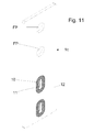
- Figure 11 is a view similar to the view of Fig. 1 of another embodiment of a structural plate component according to the present invention;
- Figure 12 is a slightly top perspective view of a bush or embossed portion or annular element for the structural plate component of Fig. 11;
- Figure 13 is a slightly top perspective view of the structural plate component of Fig. 11 during a construction step thereof;
- Figure 14 is a view similar to the view of Fig. 1 of another structural plate component embodiment according to the present invention;
- Figures 15 and 16 are slightly top perspective views taken from respective sides of a side unit obtained by assembling structural pate components according to the present invention;
- Figures 17 and 18 are exploded views of the side unit of Figs. 15 and 16;
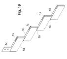
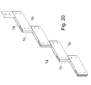
- Figures 19 and 20 are slightly top perspective views taken from respective sides of a side obtained by means of assembly of the side units of Figs. 15 and 16;
- Figure 21a and 21b are slightly top perspective views taken from respective sides of a side connection crosspiece according to the present invention;
- Figures 22a and 22b are exploded views of the crosspiece of Figs. 21a and 21b;
- Figure 23 is a slightly top perspective view of a step unit according to the present invention;
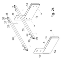
- Figures 24 and 25 are slightly top perspective views that illustrate respective assembly steps of the step unit of Fig. 23;
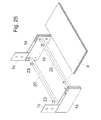
- Figure 26 is a slightly top perspective view of a staircase obtained via assembly of a plurality of step units of Fig. 23;
- Figure 27 is a cross section view taken along the line XXVII-XXVII of Fig. 26;
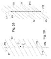
- Figures 28 and 29 are slightly side perspective views of a parapet for a staircase according to the present invention in respective positions;
- Figures 30 and 31 illustrate construction steps of the parapet of Figs. 28 and 29;
- Figures 32 and 33 are slightly top perspective views that illustrate a detail of the handrail of the parapet of Figures 28 and 29 in respective positions;
- Figure 34 illustrates an assembly step of an upright of the parapet of Figures 28 and 29 with two assembled step units of Fig. 23;
- Figure 35 are slightly top and side perspective view of a staircase provided with parapet according to the present invention;
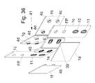
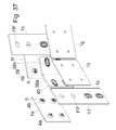
- Figures 36 and 37 are exploded views, slightly from the top and from respective sides of a side unit according to the present invention for a polygonal or helical modular staircases;
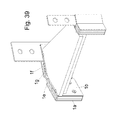
- Figures 38 and 39 are slightly top perspective views from respective sides of a tread unit for a polygonal or helical modular staircase according to the present invention;
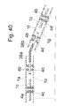
- Figure 40 is a cross section view of a detail of a tread unit of Figs. 38 and 39;
- Figures 41 and 42 are slightly top perspective views from respective sides of a helical modular staircase according to the present invention;
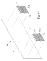
- Figs. 43 and 44 are slightly top perspective views of another embodiment of structural plate component according to the present invention, assembled and being assembled, respectively;
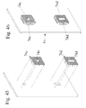
- Figs. 45 and 46 are slightly top perspective views of another embodiment of structural plate component according to the present invention, assembled and being assembled, respectively;
- Figs. 47 and 48 are slightly top perspective views from respective sides that illustrate a side unit according to the present invention in assembly step;
- Figs. 49 and 50 are slightly top perspective views from respective sides of several side units of Figs. 47 and 48 connected together;
- Figures 51 and 52 illustrate respective toothing or teeth embodiments for structural plate components according to the present invention; and
- Figures 53 and 54 illustrate a detail of two components making up part of structural plate components according to the present invention when they are in abutment, which are provided with teeth or toothing of Figs. 51 and 52, respectively.
- Figure 55 is a slightly top and exploded perspective view of another structural plate component according to the present invention;
- Figures 56 and 57 are slightly top perspective views from respective sides of a plate for the structural plate component of Fig. 43;
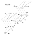
- Figures 58 and 59 are exploded, slightly top perspective views from respective sides of a side unit obtained starting from the structural plate component of Fig. 57;
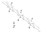
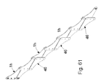
- Figures 60 and 61 are slightly top perspective views from respective sides of a side obtained by assembling the side units of Figs. 58 and 59;
- Figure 62 is a slightly top perspective view of another structural plate component according to the present invention;
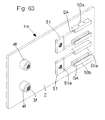
- Figure 63 is a slightly top perspective view of the structural plate component of Fig. 62 during a construction step;
- Figure 64 is a slightly top perspective view of a plate element;
- Figure 65 is a slightly top perspective view of the plate element of Fig. 64 during a construction step;
- Figures 66 and 67 are each a slightly top and exploded perspective views, taken from a respective side, of a side unit obtained by assembling structural plate components according to Figure 62, and plate elements according to Figures 64;
- Figs. 68 - 70 are slightly top perspective views that illustrate construction steps of another embodiment of structural plate component according to the present invention;
- Figs. 71 and 72 are slightly top perspective views that illustrate respective structural plate component construction steps according to the present invention;
- Figs. 73 and 74 are slightly top perspective views from respective sides that illustrate a side unit according to the present invention in assembly step; and
- Figs. 75 and 76 are slightly top perspective views from respective sides of several side units of Figs. 73 and 74 connected together;
- Fig. 77 is a slightly top perspective view of an embodiment of structural plate component according to the present invention;
- Fig. 78 is a perspective view of the structural plate component of Fig. 77 during a construction step thereof;
- Fig. 79 is a view similar to Figure 78 regarding another embodiment of structural plate component according to the present invention;
- Figs. 80 - 82 are slightly top perspective views of a plate element during respective construction steps;
- Figs. 83 and 84 are slightly top perspective views which illustrate a side unit according to the present invention, respectively in assembly and assembled step;
- Figs. 85 and 86 are slightly top perspective views from respective sides of several side units of Figs. 83 and 84 assembled together;
- Figs. 87 and 88 are views similar to Figures 77 and 78, respectively, but regard another embodiment of structural plate component according to the present invention;
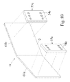
- Fig. 89 is a view similar to Figure 88 regarding another embodiment of structural plate component according to the present invention;
- Figs. 90 - 93 are views similar to Figs. 83 - 86 and regard the structural plate component of Fig. 87; and
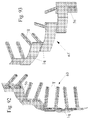
- Figs. 94 - 96 are slightly top perspective view of structural plate components similar to the structural plate component of Fig. 87 during a construction step.
-
In the drawings, equivalent or similar parts or components were marked with the same reference numerals.
-
First, with reference to Figures 1 to 6, a structural plate component or structural plate 1a for modular staircases is illustrated that has two flat main surfaces 2 with rectangular configuration and parallel to each other. The component 1a also delimits two or more openings or grooves, preferably holes 3a, 3b (four in the illustrated example) which preferably have an axis orthogonal to the main surfaces 2 and are advantageously threaded and blind.
-
The structural plate component 1a also includes at least one pre-oriented engagement means, preferably one or a more teeth 5 or recesses provided at at least one main surface and one or more holes or slots, advantageously around at least one mouth of one or more holes, preferably two holes 3b.
-
Advantageously, the pre-oriented engagement means include a plurality or sequence of teeth parallel to one another. The main surfaces have, for example, substantially rectangular border and the teeth extend substantially parallel to one side of the main surfaces, in particular the longest side of the surfaces 2. Nevertheless, the teeth can be configured in a different manner, e.g. in wave-form or with sections mutually tilted with respect to each other.
-
Preferably, the structural plate component includes two or more, preferably four bush or embossed portions 4a, 4b, preferably projecting and each including a tubular side wall delimiting a respective hole 3a, 3b and extending from one of the main surfaces. The teeth 5 extend from the free end of the tubular wall of at least one (two in the illustrated embodiment) of the projecting bush or embossed portions 4b.
-
A structural plate component 1a can be obtained, for example, by prearranging a plate 6 in which notches 7a, 7b are made, e. g. via non-through milling, for the housing of respective projecting bush or embossed portions 4a, 4b.
-
Each notch 7a has a circular section whereas each notch 7b has at least one flat side wall, extending according to a pre-established position in order to be engaged with at least one flat section of a respective wall of a bush or boss 4a, 4b.
-
Advantageously, each notch 7b is delimited, for example, by two main sides 7c parallel to each other and connected via curved sides 7d, the main sides being either parallel to the long side of the main surfaces (see Fig. 4a), or orthogonal thereto (see Fig. 6a).
-
As an alternative, the pre-oriented engagement means may be integral with the plate 6.
-
The bush or embossed projecting portions 4a, 4b instead (obtainable via numerical control machines, for example) preferably include a part of the attachment 8 from which a respective tubular side wall extends. The attachment portion 8 is intended to be precisely inserted in a respective notch 7a, 7b, and the attachment portion of the bush portions 4a thus includes a circular cross section side wall, whereas the attachment portion of the bush portions 4b includes two parallel and opposite flat sides or faces, and two curved faces.
-
The configuration of the notches 7a, 7b and the attachment part 8 are such to allow a positioning of each bush or boss with respect to the plate 6 such to ensure that the teeth are in a pre-established position with respect to the plate 6.
-
After having prearranged a bush projecting portion 4a, 4b in a notch 7a, 7b, a welding layer 9 can be applied at the edge of the side wall of the bush portion next to the plate 6, so as to fix the bush portion in position and confer structural continuity to the structural plate component. Alternatively, the bush or embossed portion 4a, 4b can be glued to the plate 6.
-
Clearly, a structural plate component 1a according to the present invention can also be obtained via a molding process of a material, such as carbon fibers and/or glass fibers in a resin matrix.
-
A structural element 1 can also be obtained by forming the tooth or recess directly on the plate. One such element can be obtained by means of laser cutting techniques of the slots and holes, and then the teeth via numerical control machines.
-
Alternatively, the tooth or the recesses can be molded on the plate by means of "molding rollers".
-
Another embodiment of structural plate component 1b is illustrated in Figures 7 to 11, which is entirely equivalent to that just illustrated, although non-threaded through holes 3c, 3d are made therein. It can therefore be obtained by means of molding of a carbon fiber and/or glass fiber material in a resin matrix, or via prearrangement of a plate 6a which is milled as indicated above, then making the holes F at the milling, and finally attaching and welding projecting bush or embossment portions 4c, 4d indicated in Figs. 8a, 8b, 9a, 9b. These are similar to the projecting bush portions 4a, 4b, respectively, which are described above, but do not delimit threaded holes, and therefore have smooth inner walls.
-
With reference to Figures 11 to 13, a flat structural plate component 1c is illustrated, preferably rectangular in shape, which has two main surfaces and delimits preferably two through bores FP and preferably two through slots or openings 10, all having axes substantially orthogonal to the main extension of the structural plate component. The element 1c also includes a pre-oriented engagement means, preferably one tooth or a plurality of teeth 11 or recesses extending at at least one main surface and at least one bore or slot, advantageously around at least one mouth of the slot(s) 10 and extending substantially parallel to the short sides of the structural plate component 1c.
-
One such structural plate component can be obtained by molding a suitable moldable material (e. g. glass fiber, carbon fiber) or prearranging a plate 12 in which one or more bores or holes FP are made (two are illustrated) and two or more slots 12b are formed (two are illustrated), then prearranging bush or embossed portions or annular elements 13 of slightly greater cross-section than that of the slots 12b. The annular elements 13 have two main faces from which the teeth 11 extend, and an edge face 14. Such elements 13 can for example be obtained via laser cutting techniques.
-
At this point, e. g. by means of presses, the bush or embossed portions or annular elements 13 are forced inside the slots 12b, thus obtaining a structural plate component 1c provided with structural continuity.
-
Another structural plate component 1d embodiment according to the present invention is illustrated in Figures 14 and 15, which is very similar to the embodiment just illustrated of structural plate component 1c. Nevertheless, it has one or presumably a pair of slots 15 mainly extending parallel to the short sides of the plate, and one or a pair of slots 16 mainly extending parallel to the long sides of the structural plate component 1d. In addition, pre-oriented engagement means are provided, e. g. one or two teeth 17 or recesses at at least one main surface and at least one bore or slots, preferably around at least one mouth of the slot(s) 15.
-
With reference to Figures 15 to 18, a side unit 18 is illustrated, which was obtained by assembling the structural plate components 1a, 1b e 1c described above.
-
More particularly, for the assembly of the unit 18, two structural tread components 1a and 1b are prearranged side by side, both with vertical trim and substantially horizontal main sides, with holes respectively aligned, in a manner such that the bush portions 4b equipped with teeth 5 of the structural component 1a are aligned with the bush portions 4d provided with teeth 5 of the structural component 1b. Between the two tread components 1a and 1b, two structural riser components 1c are arranged with vertical trim and main sides vertical in use, the two structural riser components 1c being arranged overturned with respect to each other. A structural riser component 1c is arranged in a manner such that the two slots 10 are aligned with the bush portions 4b of the structural component 1a and the bush portions 4d of the structural component 1b. The other structural component 1c is instead arranged such that the holes FP are aligned with the bush portions 4a of the structural component 1a and the bush portions 4c of the structural component 1b. At this point, the structural components are packed together so as to bring:
- the teeth 5 of the structural component 1a in abutment against the teeth 11 on one side of the first component 1c, and the teeth 5 of the structural component 1b in abutment against the teeth 11 from the other side of the first component 1c; and
- the bush portions 4a of the structural component 1a in abutment against the bush portions 4c of the structural component 1b, all being received inside the holes FP of the structural component 1c.
-
Then, in the aligned holes/slots, pins and screws are inserted that are intended to tighten the structural components 1a, 1b and 1c together, though it will be understood that the pins/screws do not have any load-bearing support function or a secondary or minor load-bearing function with respect to the structural components.
-
Indeed, as will be understood, the structural plate components are correctly positioned and bound together due to the mutual engagement of the teeth, which are brought into abutment during assembly.
-
In such a manner, a side unit is obtained in which the structural support is carried out by components (bush or embossed portions) that have a thickness and shear strength much higher than those of a pin or screw.
-
Due to the presence of the teeth and also the slots present in the structural plate component 1c, it is also possible to easily adjust the height of each side unit and thus the height of the staircase. It is in fact possible to arrange the structural riser component in several positions with respect to the structural tread components, so that it projects, in use, in a mainly vertical direction with respect to the tread elements, naturally before packing together each side unit and fixing it in position. If it is desired to raise or lower the level of the side unit, the structural riser component will be arranged with its teeth 11 at the level of an upper or lower part of the bush portions 4b and 4d (upper or lower part in use).
-
The presence of the teeth 5 and 11 and slots 10 thus allow adjusting the height of the side units and hence the height of the staircase.
-
Preferably, filling elements 19 (e. g. colored) are provided for between the structural plate components 1a, 1b and the structural plate components 1c. The filling elements 19 include a sheet in which two holes are formed; each sheet can be arranged between a component 1a, 1b and a component 1c with its holes aligned and intended to house the bush portions of a respective member 1a, 1b.
-
In Figures 19 to 20, a side obtained by assembling together the above-described side units 18 is illustrated. Such side will be obtained by connecting the side units by means of the structural riser components 1c. More particularly, adjacent side units will have a structural riser component 1c in common, such structural element having, in use, on one side its teeth 11 in engagement with the teeth 5 of structural tread components 1a and 1b of the lower side unit (lower in use), and on the other side its holes FP engaged by the bush portions 4a, 4c of the structural tread components 1a and 1b of the upper side unit (upper in use).
-
Sides or side units according to the present invention can be connected by means of a conventional crosspiece.
-
It will be understood that in place of the structural tread components 1a and 1b, a structural tread component 1d can be used. In such case, due to the slots 15, it will be possible to adjust, in a manner entirely equivalent to that described above with reference to the adjustment of the height of the side units, the relative position in the horizontal direction (horizontal in use) of adjacent side units.
-
As it will be understood, the components 1a, 1b, 1c, and 1d allow obtaining sides and thus staircases whose tightening screws or bolts are hidden when the staircase is completely assembled.
-
With reference to Figures 21a, 21b and 22a, 22b, a crosspiece 20 is illustrated including a tubular beam 21 with square, rectangular or circular cross section on the ends of a surface on which small pins 23 are fixed (e.g. via screwing), such pins intended to support a tread at free ends thereof (preferably provided with a gasket 23a). The tubular beam 21 can be closed at the ends by means of blocks 24 (e.g. welded to the beam 21) in which a through hole is formed. The blocks 24 are intended to support L-shaped brackets 26 by means of a screw or grub screw 25.
-
At the ends of the beam 21, slots 27 are also formed through which pins or screws 28 can be inserted that are intended to pass through or project with respect to the through hole made in the blocks 24.
-
For the assembly of two sides or one or more side units 18 by means of a crosspiece 20, the sides or the side units 18 are prearranged at the sides of the crosspiece, so that the two pins 28 of the beam 20 are aligned with a respective hole delimited by the assembled components of the side or the side unit.
-
Preferably, two side units 18 are prearranged at a same level, with respective structural plate components 1b facing, then the pins 28 of the beams are inserted into the respective upper holes (upper in use) of the two side units. The free end of each pin 28 will then be located in abutment against the internally threaded ends of bush portions 4a, 4b of the plate components 1a. At this point, it will be sufficient to screw the pins 28 (e. g. via a wrench insertable in the slots 27) in the internally threaded ends of the bush portions 4a, 4b in order to complete the tightening and the assembly of the sides or side units 18. Preferably, in the lower holes (lower in use) of the components 1b of the side units 18, closure plugs TC can be prearranged.
-
At this point, a tread P is placed on the small pins 23, making them slide between the free ends of the small pins 23 themselves and the free curved end of the L-shaped brackets 26, the latter ensuring the maintenance in position on the small pins 23 of the tread P. In such a manner, a staircase or one or more step units 29 are obtained.
-
In order to assemble a staircase, several step units 29 can be anchored, ensuring that the holes/slots of the riser components of a step unit are aligned with the holes/slots of tread components of an adjacent step unit, and then mutually fixing in position the two units via the insertion of pins/screws in the holes/slots now aligned.
-
With reference to Figures 28 to 35, a parapet 30 is illustrated, including an upright 31 with rectangular cross-section, which comprises a first attachment section 31a, then a second section 31b slightly wider than the first section 31a defining a pair of shoulders 31d therewith, and finally a tapered section 31c terminating with an end or tip in which a hole is made.
-
In a side wall of the second section 31b, holes are made equidistant from each other, in which bar support hooks 32 (e.g. with circular section) are insertable.
-
In the hole formed in the tapered section 31c, a fork component 34 is instead insertable and fixable in position; at the free end of the prongs 35 of such component 34, a cradle component 36 is pivotable, e. g. via a screw, for support and anchorage (e.g. via bolting) of a handrail 37.
-
Both the bars 33 and the handrail 37 can be angularly moved (see Figs. 28-30-32-33) with regard to upright 31 and cradle component 36.
-
The first section 31a of the upright 31 can be inserted between two structural components 1a and 1b of a side and fixed in position by means of screws that can be inserted in suitable seats made in a structural riser component 1c (see Fig. 34).
-
Another embodiment of structural plate component 1e according to the present invention is illustrated in Figures 36 and 37. As can be observed, it includes a curved plate comprising two sections 38a, 38b mutually tilted with respect to each other, openings or slots 39 being made in each section. The component includes two main surfaces and also includes pre-oriented engagement means, preferably teeth 40 or recesses being provided or extending at at least one main surface and at least one hole or slot of the sections 38a, 38b, preferably around both mouths of the slots 39. One such element can be made in an entirely equivalent manner to the structural plate component 1c. The teeth 40 preferably extend substantially parallel to the main side or longer side of the respective section 38a, 38b.
-
The structural plate component 1e can be used for making helical or polygonal staircases. In order to obtain a tread unit 41 of a helical staircase, a structural tread element 1a is prearranged together with a structural tread component 1b, two structural riser components 1c, a structural plate-like component 1e and also a pair of structural plate tread components 1f and 1g.
-
The structural tread components 1f and 1g are entirely equivalent, respectively, to the structural tread components 1a and 1b, nevertheless each of them only has bush or embossed portions equipped with teeth 5. The structural element 1f will therefore have four bush or embossed portions 4b, while the structural element 1g will have four bush or embossed portions 4d.
-
More particularly, such components 1f, 1g have two bushes arranged in a manner such that the teeth extend substantially parallel to the main side or longer side of the main surfaces, and two bushes arranged in a manner such that the teeth extend substantially parallel to the shorter side of the main surfaces.
-
Still more particularly, the structural plate components 1a, 1b for making helical or polygonal staircases have bush or embossed portions 4b and 4d whose teeth are parallel to the longest side of the plate-component.
-
In order to make a helical staircase side unit, the structural component 1e is prearranged with one section 38a placed between two structural components 1a and 1b, and the other section 38b placed between two structural components 1f, 1g, ensuring that each slot 39 is aligned with a respective bush portion 4a of a component 1a and a bush portion 4d of a component 1b.
-
The two structural riser components 1c, also in this case, are arranged overturned with respect to each other in use, a structural riser component 1c being arranged in a manner such that the two slots 10 are aligned with the holes or slots delimited by the bush portions 4b of the structural component 1f and the bush portions 4d of the structural component 1g. The other structural plate component 1c is instead arranged such that the holes FP are aligned with the holes or slots delimited by the bush portions 4a of the structural component 1a and the holes delimited by the bush portions 4c of the structural element 1b.
-
Then the structural components are packed together so as to bring:
- the bush portions 4a of the structural component 1a in abutment against the bush portions 4c of the structural component 1b, all being received within the holes FP of a first structural component 1c;
- the teeth 5 of the structural component 1a in abutment against the teeth 40 on one side of the first section 38a of the structural plate component 1e, and the teeth 5 of the structural component 1b in abutment against the teeth 40 on the other side of the section 38a of the structural plate component 1e;
- the teeth 5 of two bush portions 4b of the structural component 1f in abutment against the teeth 40 on one side of the second section 38b of the structural plate component 1e, and the teeth of two bush portions 4d of the structural component 1g in abutment against the teeth 40 on the other side of the section 38b of the structural plate component 1e; and
- the teeth 5 of the other two bush portions 4b of the structural component 1f in abutment against the teeth 11 on one side of the second structural component 1c, and the teeth 5 of the other two bush portions 4d of the structural component 1g in abutment against the respective teeth 11 of the second structural component 1c.
-
Pins and screws are then inserted into the aligned holes/slots, which are intended to tighten together the structural plate components 1a, 1b, 1c, 1e, 1f and 1g, without however the pins/screws having load-bearing support function; in such a manner, a helical or polygonal side unit is obtained.
-
A helical staircase side can be obtained by assembling several side units by means of the structural riser elements 1c, as described above for the straight staircases. More particularly, adjacent side units will have a structural riser component 1c in common, such structural component having, in use, on one side its teeth 11 in engagement with the teeth 5 of structural tread components 1f and 1g of the lower side unit (lower in use), and on the other side its holes FP engaged by the bush portions 4a, 4c of the structural tread components 1a and 1b of the upper side unit (upper in use).
-
By combining several tread units in such a manner, it is possible to obtain helical or polygonal staircases (see Figs. 41-42).
-
Due to the presence of the teeth 5, 11 and 40, it is possible to adjust both the height and the diameter or in any case the width of the helical staircase, as explained above with reference to the straight staircases.
-
With reference to Figures 43 and 44, a flat structural plate component 1u for modular staircases is illustrated which has two flat main surfaces 2 with rectangular configuration that are parallel to each other. The component 1u also delimits two or more openings or grooves, preferably holes 74a, 74b (four in the illustrated embodiment) which advantageously have an axis orthogonal to the main surfaces 2, and still more preferably are threaded and blind.
-
The plate component 1u also includes a pre-oriented engagement means, preferably at least a plurality of teeth 75 or recesses, which extend at at least one main surface and at least one hole or slot, advantageously around at least one inlet of the holes 74a, 74b.
-
The main surfaces have, for example, substantially rectangular border. The teeth can be configured in a different manner, e. g. in wave-form or with sections that are mutually tilted with respect to each other.
-
Preferably, the plate member includes two preferably projecting bush or embossed portions 76a, 76b, each with substantially square or rectangular border; on the outer surface (outer in use) thereof, a plurality of teeth 75 or recesses are made.
-
A first bush or embossed portion 76a delimits a threaded hole 74a, while the other portion 76b preferably delimits a plurality of holes 74b (three in the embodiment), aligned with each other and with the threaded hole 74a.
-
A plate component 1u can be obtained, for example, by prearranging a plate 6 in which notches are obtained, e. g. via non-through milling, for the housing of respective projecting bush or embossed portions 76a, 76b.
-
The bush or embossed portions 76a, 76b can be fixed via welding (preferably providing for milling before the welding) or bolting to the plate 6.
-
According to Figures 45 and 46, a structural plate component 1v according to the present invention comprises a flat plate with a pair of bush or embossed portions 76c, 76d delimiting a respective hole or slot 74c, 74d. Preferably, the upper bush portion 76c (upper in use) delimits a hole 74c, while the lower bush portion 76d (lower in use), delimits a slot 74d.
-
In order to make a side 77, a plurality of structural plate components can for example be prearranged with vertical trim; structural plate components 1u with function as tread elements and components 1v acting as riser elements.
-
More particularly, a hole 74a of a plate member 1u is arranged aligned with a hole 74c of a lower plate member 1v (lower in use), while one of the holes 74b is arranged aligned with the slot 74d of a successive, upper plate member 1v (successive, upper in use).
-
Then, tightening screws or pins are prearranged in the aligned holes and slots, tightening the plate members together and bringing the teeth of the components 1u in engagement with the teeth of the respective components 1v.
-
Also the components 1u and 1v allow obtaining sides and thus staircases whose tightening screws or bolts are hidden when the staircase is completely assembled.
-
With reference to Figs. 51 and 53, a detail of teeth or toothing DN1 is illustrated for a structural plate component according to the present invention. Such teeth are rectangular or square in cross-section thereby delimiting U-shaped notches IN1, preferably rectangular or square notches. It will be understood that a plurality of teeth DN1 ensures anchorage and thus high engagement stability between adjacent structural plate component components.
-
In Figs. 52 and 54, a variant is illustrated according to which the teeth DN2 have triangular cross-section with section decreasing from the interior towards the outside, and delimit triangular-shaped notches IN2. Due to the teeth DN2, it is possible to obtain a quick and effective anchorage between adjacent structural plate component components.
-
With structural plate components described above according to the present invention, as will be understood, it is possible to obtain straight, polygonal or helical staircases provided with high structural continuity - indeed there are no interruption points. The tightening screws and pins do not have load-bearing support function. The support function is instead ensured by the structural elements, which include and are integral with the bush or embossed portions.
-
As will be understood, moreover, with the structural plate components according to the present invention, modular staircases can be easily obtained. There are not many components, but only structural components which, also due to the presence of the pre-oriented engagement means, preferably including teeth, are quite easily arranged in a correct position with respect to each other. The operator must in fact only pay attention to bringing the teeth into mutual engagement. The screws and the nuts, as said, are inserted and tightened mainly in order to pack together of the structural components.
-
On the contrary, in order to obtain a staircase according to
EP-0 942 144 , a plurality of annular or round elements, and bare plate-like members or elements formed with a number of not threaded bores or slots, although deprived of pre-oriented engagement means, should be prearranged and packed together, which of course requires a great amount of time and accuracy in execution. Moreover, the pins or screws have the function of tightening the components one against the other and acting as structural support for the staircase, and thus the risk of collapsing under heavy loads exists.
-
With reference to Figures 55 to 57, another embodiment of structural plate component 1h is illustrated according to the present invention, which has two main, substantially flat surfaces 2 that are parallel to each other, and also a pre-oriented engagement means provided at at least one main surface 2, preferably a support track or guide means 44 intended to slidingly support at least one respective slide insert 45 delimiting at least one hole or slot therein. More particularly, the support means 44 is a C-shaped element.
-
Advantageously, the main surfaces delimit two or more openings or grooves 47a, 47b, and the pre-oriented engagement means are provided at at least one opening or groove 47b. Preferably, the grooves 47a are configured like the notches 7a described above, while the grooves 47b are configured like the notches 7b described above.
-
Preferably, the C-shaped element includes an intermediate bridge-connection section 44c of two brackets 44a, 44b, the brackets having curved free end and projecting in the same direction from respective ends of the connection section 4c.
-
Still more preferably, the support means 44 include an attachment part 44d projecting from an intermediate portion of the bridge connection section 44c and on the opposite side of the brackets 44a, 44b with respect to the connection section 44c. At the corners delimited by the connection section 44c with each bracket end 44a, 44b, a respective shoulder 44e, 44f can also be provided for, such that between each shoulder 44e, 44f and the curved end of the respective bracket 44a, 44b a guide, seat or channel S is delimited for a respective end of the insert 45.
-
Advantageously, the plate component 1h includes two or more bush or embossed portions 4e, each including a tubular side wall delimiting a respective threaded hole 3e, preferably projecting from one of the main surfaces 2.
-
A plate component 1h can be obtained by prearranging a plate member 48, in which the grooves 47a and 47b are made, e. g. by means of non-through milling, for the housing of respective projecting bush or embossed portions 4e and support means 44.
-
Then, the support means 44 and the bush or embossed portions 4e are welded or glued at the grooves. Finally, one arranges a slide insert 45, in which a hole (e.g. threaded) or slot 45a is formed, on the track or guide support means 44, so as to anchor it in a correctly oriented position with respect to the plate member 1h.
-
The main surfaces of the structural component 1h are preferably configured substantially as a triangle, still more preferably as a rectangle, e. g. with rounded corners and with slightly curved oblique side, but it will be understood that there could also be different configurations, e. g. substantially rectangular. In the embodiment illustrated in Figs. 55 to 61, two support means 44 are each anchored at a respective acute angle of a main surface, and a bush portion 4e is anchored at the right angle of a main surface. Preferably, moreover, a second bush or embossed portion 4e is provided for, anchored at an intermediate portion of a side opposite an acute angle. With one such structure, after having prearranged respective slide inserts 45 on the guide or track support means 44, a hole or slot will be obtained that is delimited at the corners of a main surface, and preferably also hole or slot made at the side opposite to the acute angle.
-
In particular, an insert 45 can be provided for in which a circular hole is made with center at a symmetry axis thereof, or inserts can be provided for in which a hole is made that is slightly off-center with respect to the symmetry axis in one direction or the other. In such a manner, it is possible to vary the relative position in the vertical direction, in use, between two successive side units, and hence the height of the side.
-
In order to make a side unit with one such structural element, the following will be alternately prearranged and then assembled together:
- one pair of structural plate components 1h with main walls 2 substantially aligned and one overturned about 180° with respect to the other, in a manner such that the holes or the slots made at the two corners of each plate component 1h are substantially in line with a hole or slot made at a corner of the other plate component 1h, such that there are two substantially parallel rows of holes or slots; and
- a pair of plate members or elements 46.
-
The plate elements 46 have substantially flat main surfaces, substantially configured as a triangle, preferably rectangle, e. g. with rounded corners and with oblique side slightly curved; a hole or slot is made therein at the corners of a main surface, preferably a hole or slot made at the side opposite an acute angle, such that also the pair of plate elements or members 46 has two substantially parallel rows of holes or slots.
-
The two plate members are also arranged with main walls substantially aligned and one overturned about 180° with respect to the adjacent member, and with holes or slots made at two corners of each plate member 46 in line with a hole or slot made at a corner of the other plate member 46.
-
The structural plate components 1h will thus be anchored to the pair of plate members 46, in a manner such that each hole or slot of a first row of holes or slots of the pair of structural plate components 1h h is substantially aligned with a respective hole or slot of a first row of holes or slots of the pair of plate members 46.
-
In the aligned holes/slots of the structural plate components 1h and plate members 46, pins and screws are inserted that are intended to tighten together such structural plate components and to be engaged in the threaded holes delimited by the bush or embossed portions 4e and inserts 45.
-
For the obtainment of a side, several above-described side units are connected together. In particular, for the connection of a lower side unit (lower in use) with a successive or upper side (successive or upper in use), the holes and slots of the second row of holes or slots of the pair of structural plate components 1h of the lower side unit (lower in use) are arranged substantially aligned with respective holes or slots of a first row of holes or slots of plate members 46 of the upper side unit; then, in the aligned holes/slots of the structural plate components 1h and plate members 46, pins and screws are inserted that are intended to tighten together the two side units.
-
A side and thus a staircase obtained by means of pairs of structural plate components 1h and plate members 46 can be easily and quickly assembled, since once the height of the staircase is evaluated, all of the necessary components are prearranged, i. e. structural plate components 1h, plate members 46, inserts 45, pins or screws, after which the inserts are arranged on the respective support means. At this point, it will suffice to align the holes or slots of the structural plate components 1h with the holes or slots of the plate members 46 and insert pins or screws in the aligned holes in order to complete the assembly of each side.
-
Subsequently, the sides will be connected via a crosspiece as described above and respective treads will be prearranged, in such a manner obtaining a modular staircase.
-
With structural plate components according to the present invention, therefore, the support means 44 and the bush or embossed portions 4e are fitted (e. g. by means of gluing or welding) on the respective plate 6b, while the inserts 45 are supported by the support means, and then the operator must only pay attention to prearrange the structural plate component 1h and plate members 46 in correct relative position. This differs from the modular staircases according to the prior art, where for the obtainment thereof, during the packing together and assembly of the components of a side, attention must be made to suitably position both the plate members and the spacers.
-
With reference to Figs. 62 to 67, a structural plate component 1m according to the invention is illustrated, similar to embodiment 1h, but provided with a pre-oriented engagement means including a support means 50a, 50b for a respective insert 51 delimiting a bore or hole 51a. The support means 50a, 50b preferably delimit one or more sliding guiding guides or seats SA for the insert 51, preferably one or more channels, the seat(s) SA extending further than the insert 51 such that the latter can be made to slide and then fixed in different positions with respect to the support means, and hence with respect to the main surfaces 2 of the structural plate component 1m.
-
Preferably, the support means include two substantially C-shaped brackets 50a, 50b, each delimiting a guide seat or channel SA for a respective end of the insert 51; the two seats SA are turned towards one another.
-
Advantageously, the main surfaces 2 of the structural plate component 1m are of substantially rectangular configuration, and the support means delimit a housing channel or housing channels substantially parallel to the greater side of the main surfaces 2.
-
The plate member 1m then includes two or more bush or embossed portions 4f, each including a tubular side wall delimiting a respective threaded hole 3f and preferably projecting from one of the main surfaces 2. Each bush or embossed portion 4f preferably comprises a main part extending from a respective main surface 2 and a terminal shank with lesser outer diameter than the main part.
-
A structural plate component 1m can be used as a tread element for a staircase, whose riser elements are, for example, constituted by plate elements or members 53 of substantially rectangular configuration, in which four holes are formed. Preferably, each plate member 53 is made by providing for an opening in which a block 53a delimiting a hole is molded.
-
A side of the staircase is formed by a succession of plate tread components 1m, each arranged, in use, with substantially vertical trim, and plate riser components 53 with substantially vertical trim being intended to connect together two consecutive plate tread components 1m. More particularly, each plate member 53 is arranged with two holes aligned with the holes delimited by the inserts 51 of a plate tread component 1m, and two holes aligned with the holes delimited by the bushes 4f of a successive plate tread component 1m. In the aligned holes/slots of the structural plate components 1m and plate members 53, pins and screws are inserted that are intended to tighten together such structural plate components and to be engaged in the threaded holes delimited by the bush or embossed portions 4f and inserts 51.
-
Two side units thus obtained can be anchored by means of crosspieces, e. g. as described above.
-
A structural plate component 1m can be obtained, for example, as described with reference to the plate component 1h.
-
As will be understood, with a structural plate component 1m, in particular with main surfaces with substantially rectangular configuration and guide channels substantially parallel to the greater side of the main surfaces 2, it is possible to obtain sides with tread of different width. This is due to the size of the seat(s) or channel(s) SA, in which, as said, it is possible to slide and fix the inserts 51 in different positions.
-
In order to vary the rise of one such side, different inserts 51 and blocks 53a can be used, more particularly inserts 51 and blocks 53a with holes made in an upper, intermediate or lower position thereof (in use).
-
It will be understood that a structural plate component according to the present invention can be obtained by fixing, e. g. gluing or welding bush or embossed portions 4a, 4b to a plate 6b; such component would then have substantially triangular main surfaces, with at least one opening or groove being made at a corner of the main surfaces and at least two openings or grooves being formed at the side opposite such corner.
-
With reference to Figures 68 to 76, another embodiment of structural plate component 1s according to the present invention is illustrated, which has two substantially main flat surfaces 2 that are parallel to each other, and also has a pre-oriented engagement means, preferably a track or guide support means 64 intended to support a respective slide insert 65.
-
Still more preferably, the support means 64 is substantially C-shaped, so as to delimit seats S, upper and lower in use, for a respective end of the insert 65.
-
Advantageously, the plate member 1s includes a bush or embossed portion 4g, including a tubular side wall delimiting a respective threaded hole 3g and preferably projecting from one of the main surfaces 2.
-
A plate member 1s can be obtained by prearranging a plate 6 in which grooves are made, e. g. by means of non-through milling, for the housing of respective projecting bush or embossed portions 4g and support means 64. The support means 64 and the bush or embossed portions 4g can then be welded at the grooves and finally the insert 65 is arranged on the support means 64.
-
It will be understood that the support means 64 and the bush portions 4g can alternatively be welded to the plate 6; one or more millings can be made on the plate 6, at which the support means 64 can be prearranged and fixed together with the bush portions 4g, but such preceding milling step may not be provided for. The support means 64 can also be fixed via bolting to the plate 6. According to one variant, a plurality of nuts are welded on the plate 6, while seats are made in the support means 64, each seat intended to be engaged with a respective nut. In order to complete the assembly, the bolts are prearranged in the respective seats, and then they are engaged for screwing via screws.
-
The insert 65 delimits a threaded hole 66 and a toothing 67 is also made on its free surface. In use, the hole 66 is preferably horizontally aligned with the hole 3g delimited by the bush or embossed portion 4g.
-
In the insert 65, one or a pair of slots 68 can then be made, on opposite sides from each other with respect to the threaded hole 66. At such slots 68, a screw is insertable, intended to be screwed in a threaded seat SF made on the support component 64 or directly on the plate 6, so as to fix the insert 65 in position on the support component 64.
-
With reference to Figs. 71 and 72, a structural plate component 1t is illustrated with preferably rectangular configuration, which has two main surfaces and delimits a through hole 69 and a through slot or opening 70 having axis substantially orthogonal to the main extension of the structural plate component. The component 1t also includes a pre-oriented engagement means, such as a plurality of teeth 71 extending at at least one main surface of the slot 70, advantageously around at least one inlet of the slot(s) 70.
-
The structural plate component 1t can be obtained by prearranging a plate in which the hole 69 is formed along with a slot and then fixing a projecting portion 72 delimiting a slot (which will be substantially aligned with the slot made or delimited by the plate), on which the plurality of teeth 71 are made. The fixing of the projecting portion 72 can be made by means of welding, milling and then welding at the milling seats, or bolting.
-
A side for staircases can be made by prearranging a plurality of structural plate components 1s, carrying out the function of tread elements, and a plurality of structural plate components 1t, carrying out the function of riser elements, all the structural plate components being arranged with vertical trim.
-
The hole 3g of each structural plate component 1s is aligned with the hole 69 of a lower structural plate component 1t (lower in use), while the hole 66 delimited by the same structural plate component 1s is aligned with a slot 70 of a successive, upper structural plate component 1t (successive, upper in use).
-
Screws or pins are then inserted in the aligned holes and slots, which will be screwed in the threaded holes 3g and 66, in such a manner tightening together the plate members 1s and 1t and bringing the teeth 71 of the structural plate components 1s in abutment against the teeth 71 of the structural plate components 1t, and thus allowing the assembly of a side 73.
-
According to such solution, the engagement between the teeth or toothing allows correctly and firmly positioning and anchoring the structural plate components together, while the pins/screws do not carry out a support load-bearing function, or in any case they perform a secondary load-bearing function with respect to the teeth.
-
The width of the side can be adjusted by moving the insert 65 with regard to the respective support means 64, while the height of the side is adjusted by aligning the hole 66 with a lower portion (maximum height of the side), upper portion (minimum height of the side) or intermediate portion of a respective slot 70.
-
It will be noted (see Fig. 76 in particular) that sides and thus staircases obtainable from the plate members 1s and 1t do not have visible bolts and screws once assembled, more particularly bolts, pins or screws are not visible at the outer surface of the sides.
-
As it will be understood, for the structural plate components 1m and 1s considerations similar to those made in connection with the structural plate component 1h applied, i. e. it is quite easy to assemble a staircase, because the operator must only pay attention to prearrange the structural plate component 1m, 1s and plate members 53 or structural plate component 1t t in correct relative position.
-
In so far as the above-cited prior art documents are concerned,
DE-197 04 957 teaches a staircase having a non-modular staircase sides and provided with a device for connecting the staircase sides to staircase steps, whereas
EP-0 942 144 relates to a modular staircase including modular sides or side units comprising a plurality of components assembled together. A person skilled in the art is not directed to combine the teachings of such prior art documents, which relate to different kinds of staircase, and as a matter of fact the structure of staircase having a modular side is quite different from the structure of a staircase having a non-modular side. In any case, the side unit of a staircase according to
EP-0 942 144 clearly differs from the side of the staircase according to
DE-197 04 957 , and the person skilled in the art should substantially modify (i. e. exert inventive activity) the device of
DE-197 04 957 in order to adapt it to the side unit of
EP-0 942 144 . Moreover, the side unit of
EP-0 942 144 is provided with its own anchoring means for a step, and the skilled person is in no way directed to adopt different means for anchoring the side unit to the various steps.
-
It should aslo be borne in mind that the device of
DE-197 04 957 is suitable for anchoring a side to a step, whereas the support means and inserts of the
structural plate components 1h, 1m and 1s are designed to connect structural plate components among themselves. Finally, should the person skilled in the art combine the teachings of
EP-0 942 144 and
DE-197 04 957 , he or she would not obtain a structural plate component similar to the
structural plate component 1h, 1m and 1s of the application invention.
-
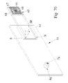
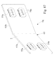
Referring now to Figures 77 and 78, a flat, structural plate component 1n for modular staircases is illustrated that has two flat main surface 2 with preferably rectangular configuration and parallel to each other. The component 1n also delimits two or more openings or holes 54a, 54b, which preferably have an axis orthogonal to the main surfaces 2 and are advantageously threaded and blind.
-
The plate member 1n also includes a pre-oriented engagement means including at least a pair of relief components or projecting members 55a, 55b, each delimiting a respective threaded hole or holes 54a, 54b and extending from one of the main surfaces.
-
More particularly, four projecting members 55a, 55b are provided for, each arranged at a respective corner of the plate member 1n; in two projecting members 55a placed at a face of the plate member 1n, a series or plurality of holes 54a are made (three in the drawings), horizontally aligned in use. The holes 54a of each row are preferably horizontally aligned, in use, with a respective hole 54b.
-
The two projecting members 55a, 55b placed on the same face of the plate member 1n also have respective 54a, 54b that are vertically aligned in use.
-
The plate component 1n can be made by prearranging a plate 6 and then by welding (long edge portions) or bolting the projecting members 55a, 55b on the plate 6. Advantageously, in the projecting members 55a, 55b, threaded through holes are made, and when the components themselves are fixed on the plate 6, a structural plate component is obtained with threaded and blind holes. Before fixing the projecting members 55a, 55b, it is possible to form milling on the plate 6 (milling with depth equal to about 2-4 mm) at which the projecting members 55a, 55b are prearranged and fixed.
-
As will be understood, both the plate 6 and the projecting members 55a, 55b can have different sizes and shapes.
-
The plate component 1n is preferably made of steel, but it can also be made of carbon fiber and/or glass fiber in a resin matrix, in which case the plate element can be made by a molding process (for example).
-
According to one modification, a structural plate component 1p (see Fig. 79) according to the present invention has two projecting members 55c, 55d, e. g. with rectangular border and much greater size than the projecting members 55a, 55b. Each projecting member 55c, 55d is arranged at a respective face of the plate member 1p; in at least one projecting member 55c, a plurality of holes are made (six in the Figure), arranged aligned on two or more parallel rows, while in the other projecting member 55d at least two vertically-aligned holes 54d are made.
-
Each hole of a row of holes 54c is also vertically aligned with a hole of another row of holes 54c.
-
A structural plate component 1n or 1p can be used as a tread element for a staircase, whose riser components are, for example, constituted by plate element or members 56 (see Figs. 80 - 82) with substantially rectangular configuration, which delimit four holes 56a, 56b that are vertically aligned in use. Preferably, each plate member 56 is made by providing for one or a pair of openings 56c in which an insert 57 is positioned delimiting a hole 56a.
-
Different inserts 57 can be used, more particularly inserts 57 with holes made in an upper, intermediate or lower portion (in use), thus allowing, as will be better explained below, the obtainment of sides and hence staircases with different rise.
-
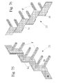
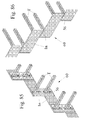
In order to make a side 60 (see Figs. 83 - 86) from structural plate tread components 1n or 1p and plate riser elements 56, a plurality of plate components 1n or 1p are prearranged together with a plurality of plate members 56, all arranged with vertical trim; each plate component 1n or 1p is arranged with two holes 54a or 54c delimited by the projecting members 55a or 55c aligned with the holes 56b of a lower plate member 56 (lower in use), and two holes 54b or 54d delimited by the projecting members 55b or 55d aligned with the holes 56a of a successive, upper plate member 56 (successive, upper in use).
-
In the aligned holes/slots of the structural plate components 1n or 1p and plate members 56, pins and screws 58 are inserted. These are intended to tighten together such plate components 1n or 1p and plate members 56 and to be engaged in the threaded holes delimited by the projecting members 55a, 55b, 55c or 55d.
-
A side 60 can be connected via crosspieces T to another side 60 or to a wall, thus obtaining a straight staircase (not illustrated in the drawings).
-
As will be understood, if inserts 57 are used with holes made in an upper portion thereof (upper in use), a staircase with minimum height will be obtained, while using inserts 57 with holes obtained in a lower portion thereof (lower in use), a staircase with maximum height will be obtained. In order to obtain a staircase with intermediate height, inserts 57 will instead be used with holes made in a median portion (see embodiment illustrated in the Figures).
-
Due to the rows of holes 54a or 54c, it is also possible to vary the width of the tread. Indeed, if the holes 56b of the plate members 56 are aligned with the distal holes 54a or 54c or those further from the holes 54b or 54d of the same plate component 1n or 1p, a tread with maximum width would be obtained, while by aligning the holes 56b of the plate members 56 with the proximal holes 54a or 54c, or those closer to the holes 54b or 54d of the same structural plate component 1n or 1p, a tread with minimum width would be obtained. Finally, if the holes 56b of the plate members or elements 56 are aligned with the holes 54a or 54c of a structural plate component at an intermediate distance from the holes 54b or 54d of the same plate component 1n or 1p, a tread of intermediate width can be obtained.
-
As will be understood, due to the structure of the structural plate components 1n and 1p, it is possible to obtain sides for modular staircases with hidden tightening screws and bolts. In particular, at the outer surface of the sides (see Fig. 86 in particular), bolts or screws do not exit outward therefrom or are not in sight.
-
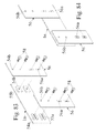
With reference now to Figures 87 to 93, variants of structural plate components 1q and 1r are illustrated as well as a side obtainable from a plurality of structural plate components 1q and plate members 56.
-
The structural plate component 1q includes a curved plate 61 provided with two sections or segments 61a, 61b that are mutually tilted with respect to each other.
-
The structural plate component includes two main surfaces 2 and also includes pre-oriented engagement means, preferably projecting members 55a, e.g. bolted or welded at the sections or segments 61a, 61b.
-
More particularly, four projecting members 55a are provided for, each arranged at a respective outer corner of the structural plate component 1q, two projecting members 55a will then be at a section 61a, while the other projecting members 55a will be at the other section 61b; in the projecting members 55a, a plurality of holes 54a are made (three in the drawings), aligned horizontally in use. Advantageously, in the projecting members 55a, and when the same components are fixed on the sections 61a, 61b, a structural plate component 1q is obtained with threaded and blind holes. Each row of threaded holes 54a on a projecting member 55a provided at a section 61a of the curved plate 61 is preferably at the same level of the row of holes 54a made on a projecting member 55a arranged at the other section 61b of the curved plate 61.
-
The two projecting members 55a placed on the same sections 61a or 61b of the structural plate component 1q also have respective holes 54a, vertically aligned in use.
-
With reference to Figure 89, a structural plate component 1r is illustrated that is entirely equivalent to the structural plate component 1q, but having projecting members 55c in place of projecting members 55a on the same section 61a, 61b of the plate member 61.
-
More preferably, a structural plate component according to the present invention may be obtained by the following steps:
- pre-arranging or obtaining at least one pre-oriented engagement means;
- pre-arranging a structural plate;
- fixing pre-oriented engagement means to the plate;
- bending the structural plate at an intermediate portion thereof, thus obtaining two angled sections, at least one pre-oriented engagement means being provided in each section.
-
Should the pre-oriented engagement means include projecting members 55a or 55c, then the structural plate is bended along one axis substantially orthogonal with respect to the alignment direction of a plurality of aligned holes formed in projecting members rigid with the structural plate.
-
A plate member 1q or 1r r can be used for making sides of helical staircases. For such purpose, a plurality of structural plate components 1q or 1r are prearranged along with a plurality of plate members 56; then, a hole 54a or 54c of the projecting members 55a or 55c placed on a section 61a of the structural plate component 1q or 1r is aligned with the holes 56b of a lower plate member 56 (lower in use) and a hole 54a or 54c of the projecting members 55a or 55c placed on the other section 61b of the structural plate component 1q or 1r aligned with the holes 56a of a successive, upper plate member 56 (successive, upper in use). Pins or screws 58 are then inserted in the aligned holes or openings, intended to tighten together the structural plate component 1q or 1r and plate members 56 and to be engaged via screwing in the threaded holes delimited by the projecting members 55a or 55c, thus obtaining a side 63 for helical staircases that can be connected by means of crosspieces T, e.g. to a central pillar or to another side 63.
-
The adjustment of the height of the side and thus of the staircase can be made in the same manner described above with reference to Figures 77 to 86 with regard to a straight staircase, while the adjustment of the width of the tread and hence of the helix is obtained by aligning the holes of the plate-like riser components 56 with the holes 54a or 54c that are arranged on a section 61a or 61b of lesser distance (or proximal, obtaining a tread with minimum width), of greater distance (or distal, obtaining a tread with maximum width) or of intermediate distance (obtaining a tread with intermediate width) with respect to the other section 61b or 61a.
-
In the same manner as the structural plate component 1n and 1p, the structural plate component 1q and 1r r have a structure such to allow making staircases that, once assembled, do not have visible tightening screws or bolts.
-
It should also be noted that all the structural plate components according to the present invention allow obtaining modular staircases having different heights, and in the case of helical or polygonal staircases, different width.
-
Figures 94 to 96 show structural plate components while being constructed. As it will be understood, such Figures show that different structural plate components may be obtained by fixing projecting members 55a, 55b, 55c, 55d on a plate 61, e. g. at least two projecting members in which one or more holes or bores are formed.
-
Clearly, plates formed with threaded holes located at different positions make it possible to obtain staircases having different length (if a linear staircase is to be obtained) or width (if a helical or polygonal helical staircase is to be obtained).
-
Preferably, according to the present invention each projecting member delimits a plurality of holes or bores (three in the drawings), horizontally aligned in use. The holes or bores in each member can be located at a distance one from the other that may be determined as a function of the staircase to be obtained.
-
Of course, should pins or screws be inserted after the components of the staircase are packed:
- in the external (in use) holes or bores of each projecting member a linear staircase having maximum length is obtained,
- in the internal (in use) holes or bores of each projecting members a linear staircase having minimum length is obtained, and
- in the intermediate (in use) holes or bores of each projecting members a linear staircase having an intermediate length is obtained.
-
Following the method according to the present invention, advantageously, the length or width of a staircase to be obtained is first evaluated, then the kind of plates and projecting members to be used are determined, i. e. the size and shape of the plate and the position of the hole or bore in it (if projecting members with one hole only are used) or the relative position of the holes or bores (if projecting members having a plurality of holes are used) in each projecting member are determined. Moreover, the position of the projecting members on the plate is established, preferably, so that the axis of symmetry of each projecting member extends at a specific distance from a respective edge of the plate.
-
Thus, by using different projecting members, i. e. projecting members formed with a bore or hole at a specific position, and preferably a plurality of bores or holes at a specific distance therebetween, a large number of staircases having a plurality of lengths or widths can be obtained.
-
According to the present invention it is also provided a reckoning method which, once the size of a staircase, e. g. the length of a linear staircase, or the width of a helical staircase to be obtained are established, allows the specific size of the plates, position of the projecting members on the plate, and the position of the bore or hole on each projecting member to be determined.
-
Figs. 94 to 96 show curved structural plate components which are specifically designed for obtaining a helical staircase. However, it is to be understood that similar considerations apply to linear structural plate components (e. g. structural plate component 1n) designed to obtain linear structural staircases.
-
The structural plate component, the staircase and the method described above are susceptible to numerous modifications and variants within the protection scope defined by the tenor of the claims.
-
Thus, for example, the structural plate components 1a, 1b, 1c, 1d, 1e, 1f and 1g could have pre-oriented engagement means including at least one recess, intended in use to be engaged with a respective tooth of another structural plate component.
-
In the drawings three main kinds of structural plate components are shown that are designed to constitute alternative solutions to a specific technical problem, i. e. that of providing a structural plate component for modular sides of a staircase which can be assembled with other modular staircase components in an easy and quick manner, thus obtaining in a simple and rapid way a staircase side.