EP2261153A2 - Transport Apparatus - Google Patents
Transport Apparatus Download PDFInfo
- Publication number
- EP2261153A2 EP2261153A2 EP10165767A EP10165767A EP2261153A2 EP 2261153 A2 EP2261153 A2 EP 2261153A2 EP 10165767 A EP10165767 A EP 10165767A EP 10165767 A EP10165767 A EP 10165767A EP 2261153 A2 EP2261153 A2 EP 2261153A2
- Authority
- EP
- European Patent Office
- Prior art keywords
- drive train
- pawl
- transport element
- torque
- support member
- Prior art date
- Legal status (The legal status is an assumption and is not a legal conclusion. Google has not performed a legal analysis and makes no representation as to the accuracy of the status listed.)
- Granted
Links
Images



Classifications
-
- B—PERFORMING OPERATIONS; TRANSPORTING
- B65—CONVEYING; PACKING; STORING; HANDLING THIN OR FILAMENTARY MATERIAL
- B65H—HANDLING THIN OR FILAMENTARY MATERIAL, e.g. SHEETS, WEBS, CABLES
- B65H31/00—Pile receivers
- B65H31/30—Arrangements for removing completed piles
- B65H31/3081—Arrangements for removing completed piles by acting on edge of the pile for moving it along a surface, e.g. by pushing
-
- B—PERFORMING OPERATIONS; TRANSPORTING
- B43—WRITING OR DRAWING IMPLEMENTS; BUREAU ACCESSORIES
- B43M—BUREAU ACCESSORIES NOT OTHERWISE PROVIDED FOR
- B43M3/00—Devices for inserting documents into envelopes
- B43M3/04—Devices for inserting documents into envelopes automatic
-
- B—PERFORMING OPERATIONS; TRANSPORTING
- B65—CONVEYING; PACKING; STORING; HANDLING THIN OR FILAMENTARY MATERIAL
- B65G—TRANSPORT OR STORAGE DEVICES, e.g. CONVEYORS FOR LOADING OR TIPPING, SHOP CONVEYOR SYSTEMS OR PNEUMATIC TUBE CONVEYORS
- B65G19/00—Conveyors comprising an impeller or a series of impellers carried by an endless traction element and arranged to move articles or materials over a supporting surface or underlying material, e.g. endless scraper conveyors
- B65G19/18—Details
- B65G19/22—Impellers, e.g. push-plates, scrapers; Guiding means therefor
- B65G19/24—Attachment of impellers to traction element
- B65G19/245—Attachment of impellers to traction element for article conveyors, e.g. for container conveyors
-
- B—PERFORMING OPERATIONS; TRANSPORTING
- B65—CONVEYING; PACKING; STORING; HANDLING THIN OR FILAMENTARY MATERIAL
- B65G—TRANSPORT OR STORAGE DEVICES, e.g. CONVEYORS FOR LOADING OR TIPPING, SHOP CONVEYOR SYSTEMS OR PNEUMATIC TUBE CONVEYORS
- B65G21/00—Supporting or protective framework or housings for endless load-carriers or traction elements of belt or chain conveyors
- B65G21/20—Means incorporated in, or attached to, framework or housings for guiding load-carriers, traction elements or loads supported on moving surfaces
- B65G21/22—Rails or the like engaging sliding elements or rollers attached to load-carriers or traction elements
-
- B—PERFORMING OPERATIONS; TRANSPORTING
- B65—CONVEYING; PACKING; STORING; HANDLING THIN OR FILAMENTARY MATERIAL
- B65H—HANDLING THIN OR FILAMENTARY MATERIAL, e.g. SHEETS, WEBS, CABLES
- B65H29/00—Delivering or advancing articles from machines; Advancing articles to or into piles
- B65H29/16—Delivering or advancing articles from machines; Advancing articles to or into piles by contact of one face only with moving tapes, bands, or chains
-
- B—PERFORMING OPERATIONS; TRANSPORTING
- B65—CONVEYING; PACKING; STORING; HANDLING THIN OR FILAMENTARY MATERIAL
- B65H—HANDLING THIN OR FILAMENTARY MATERIAL, e.g. SHEETS, WEBS, CABLES
- B65H2301/00—Handling processes for sheets or webs
- B65H2301/40—Type of handling process
- B65H2301/42—Piling, depiling, handling piles
- B65H2301/422—Handling piles, sets or stacks of articles
- B65H2301/4226—Delivering, advancing piles
- B65H2301/42266—Delivering, advancing piles by acting on edge of the pile for moving it along a surface, e.g. pushing
-
- B—PERFORMING OPERATIONS; TRANSPORTING
- B65—CONVEYING; PACKING; STORING; HANDLING THIN OR FILAMENTARY MATERIAL
- B65H—HANDLING THIN OR FILAMENTARY MATERIAL, e.g. SHEETS, WEBS, CABLES
- B65H2403/00—Power transmission; Driving means
- B65H2403/70—Clutches; Couplings
- B65H2403/72—Clutches, brakes, e.g. one-way clutch +F204
- B65H2403/724—Clutches, brakes, e.g. one-way clutch +F204 electromagnetic clutches
-
- B—PERFORMING OPERATIONS; TRANSPORTING
- B65—CONVEYING; PACKING; STORING; HANDLING THIN OR FILAMENTARY MATERIAL
- B65H—HANDLING THIN OR FILAMENTARY MATERIAL, e.g. SHEETS, WEBS, CABLES
- B65H2404/00—Parts for transporting or guiding the handled material
- B65H2404/30—Chains
- B65H2404/31—Chains with auxiliary handling means
- B65H2404/311—Blades, lugs, plates, paddles, fingers
-
- B—PERFORMING OPERATIONS; TRANSPORTING
- B65—CONVEYING; PACKING; STORING; HANDLING THIN OR FILAMENTARY MATERIAL
- B65H—HANDLING THIN OR FILAMENTARY MATERIAL, e.g. SHEETS, WEBS, CABLES
- B65H2404/00—Parts for transporting or guiding the handled material
- B65H2404/30—Chains
- B65H2404/33—Means for guiding chains
-
- B—PERFORMING OPERATIONS; TRANSPORTING
- B65—CONVEYING; PACKING; STORING; HANDLING THIN OR FILAMENTARY MATERIAL
- B65H—HANDLING THIN OR FILAMENTARY MATERIAL, e.g. SHEETS, WEBS, CABLES
- B65H2515/00—Physical entities not provided for in groups B65H2511/00 or B65H2513/00
- B65H2515/30—Forces; Stresses
- B65H2515/32—Torque e.g. braking torque
Definitions
- the present invention relates to apparatus for transporting documents in a paper handling apparatus.
- Documents such as sheets or stacks of paper are typically transported between separate modules of a paper handling apparatus, such as a mailing machine. For example they may be transported from storage hoppers to a collating station, where a pack of multiple sheets and other items may be assembled into a pack, and subsequently to an inserting station where the pack is pushed into an envelope. This transport is typically done by pushing using a pawl mounted on a drive train.
- apparatus for transporting documents in a paper handling system comprising: a drive train; a document transport element connected to the drive train for moving documents; and means adapted to apply a predetermined torque when the transport element is not loaded and to apply a reduced torque a predetermined time after the transport element engages a document to be moved.
- the drive chain may be driven by an electromagnetic friction clutch which transmits a torque when a DC voltage is applied.
- the torque is proportioned to the voltage.
- apparatus for transporting documents in a paper handling system comprising: a flexible drive train; a document transport element connected to the drive train for moving documents; and means for constraining the flexible drive train to move along a predetermined serial path
- the transport element comprises a pawl and a pawl support member wherein the pawl extends orthogonal to the drive train, and the support member extends rearwardly in the direction of travel of the drive train, and overlies the drive train to restrain movement of the drive train out of the predetermined path.
- the apparatus comprises at least one roller connected to the drive train and constrained for uni-dimensional movement in a guide channel.
- the transport element is arranged to push documents, but anyone skilled in this technical field will understand that equivalent elements may be used to pull documents or to lift them.
- the element may be an upstanding pawl with a pawl support member extending rearwardly in the direction of travel of the drive train.
- the drive train is preferably a chain with a plurality of chain links and the support member may have a base length extending over at least two chain links.
- the roller may be mounted adjacent and parallel to the drive chain.
- the pawl support member preferably overlies the drive chain at least in part, and it prevents the chain buckling upwardly.
- a fixedly mounted pusher/puller roller may be used.
- a pawl 1 pushes a document pack 2 in the direction of arrow 3.
- the pawl 1 is connected between two adjacent links 4 and 5 of a chain 6 which forms the drive train for the pawl 1.
- the pawl has a backwardly extending support portion 7 for extra stability and strength.
- Figure 2 illustrates the situation if there is a paper jam in the apparatus such that resistance is encountered to movement of the document pack 2.
- the drive train continues to try to move forward in the direction of arrow 3 causing the document pack 2 to buckle.
- the reaction force causes the pawl 1 to bend over backwards which releases the force on the main driving mechanism.
- the drive train 6 buckles as the pawl 1 is pushed backwards.
- a pawl 1 drives a document pack 2 in the direction of arrow 3 via chain link drive 6.
- the pawl 1 has a much longer backwardly extending portion 7 which extends over more than two chain links in this example, but could be more.
- the background portion 7 rests over the top of the chain 6 and in this example is angled to cover the width of the chain.
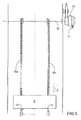
- Figure 5 shows document pack 2 being pushed in the direction of arrow 3 by two pawls 1a and 1b on parallel guide chains 6a, 6b.
- the chains 6a, 6b are driven by an electromagnetic friction clutch 10 which transmits a torque when a DC voltage is applied to it.
- the torque is related to the value of the DC voltage applied via wires 11.
- a voltage such that the maximum possible torque is transmitted from the clutch.
- the friction clutch 10 drives rod 12 which is connected to the two chain link drive trains 6a and 6b, to drive them around pulley wheels as shown more clearly in Figure 6 .
- the drive chains 6a and 6b are connected to three pulley wheels 13, 14 and 15.
- the pawl rest position is shown at 1c adjacent pulley wheel 13.
- the insert pawl is driven from rest position 1c through a distance x to position 1 to pick up the document pack 2 which it has to move.
- the clutch torque is kept at its maximum through the distance x so that the system can overcome the sudden increase in inertia at the point where the pawls start to drive the mass of the document pack 2.
- FIGS 7 to 9 illustrate more clearly the connection of the pawl 1 to the drive chain 6.
- two chain spindles 16 are elongated and have rollers 8 mounted on them outside the line of the chain 6 itself. These rollers 8 move in and are constrained by a guide channel 9. This ensures that the pawl remains upright regardless of the force acting on it.
- the insert pawl 1 and its associated drive chain 6 could be replaced by flighted timing belts, rollers or shafts to push or otherwise transport the documents.
Landscapes
- Engineering & Computer Science (AREA)
- Mechanical Engineering (AREA)
- Feeding Of Articles By Means Other Than Belts Or Rollers (AREA)
- Sheets, Magazines, And Separation Thereof (AREA)
- Delivering By Means Of Belts And Rollers (AREA)
Abstract
Description
- The present invention relates to apparatus for transporting documents in a paper handling apparatus.
- Documents such as sheets or stacks of paper are typically transported between separate modules of a paper handling apparatus, such as a mailing machine. For example they may be transported from storage hoppers to a collating station, where a pack of multiple sheets and other items may be assembled into a pack, and subsequently to an inserting station where the pack is pushed into an envelope. This transport is typically done by pushing using a pawl mounted on a drive train.
- It is desirable that such apparatus be capable of handling a variety of sizes and weights of packs without damage occurring to the mechanisms even if a paper jam occurs. In a known such apparatus, marketed as under the trade mark MaxiMailer™ by PFE International Limited, this was achieved by allowing the pawl to be pushed backwards if a force above a predetermined one is applied to it and making the drive train flexible so that it is not damaged itself. However this arrangement can only cope with relatively low loads and there is a need for apparatus which will handle much heavier loads for which the pawl must be fixed and not be allowed to move from its upright position.
- According to a first aspect of the invention there is provided apparatus for transporting documents in a paper handling system, comprising: a drive train; a document transport element connected to the drive train for moving documents; and means adapted to apply a predetermined torque when the transport element is not loaded and to apply a reduced torque a predetermined time after the transport element engages a document to be moved.
- The drive chain may be driven by an electromagnetic friction clutch which transmits a torque when a DC voltage is applied. Preferably the torque is proportioned to the voltage.
- According to a second aspect of the present invention there is provided apparatus for transporting documents in a paper handling system, the apparatus comprising: a flexible drive train; a document transport element connected to the drive train for moving documents; and means for constraining the flexible drive train to move along a predetermined serial path wherein the transport element comprises a pawl and a pawl support member wherein the pawl extends orthogonal to the drive train, and the support member extends rearwardly in the direction of travel of the drive train, and overlies the drive train to restrain movement of the drive train out of the predetermined path.
- According to one embodiment the apparatus comprises at least one roller connected to the drive train and constrained for uni-dimensional movement in a guide channel.
- Preferably the transport element is arranged to push documents, but anyone skilled in this technical field will understand that equivalent elements may be used to pull documents or to lift them. The element may be an upstanding pawl with a pawl support member extending rearwardly in the direction of travel of the drive train.
- The drive train is preferably a chain with a plurality of chain links and the support member may have a base length extending over at least two chain links. The roller may be mounted adjacent and parallel to the drive chain. The pawl support member preferably overlies the drive chain at least in part, and it prevents the chain buckling upwardly. However, a fixedly mounted pusher/puller roller may be used.
- For a better understanding of the present invention and to show how the same may be carried into effect, reference will now be made to the accompanying drawings, in which:
-
Figure 1 is a schematic side view of a prior art apparatus; -
Figure 2 is a schematic side view of the apparatus ofFigure 1 in the event of a paper jam; -
Figure 3 is a schematic side view of part of the apparatus according to the invention; -
Figure 4 is a schematic side view of the apparatus ofFigure 3 in the event of a paper jam; -
Figure 5 is a top plan view of the apparatus according to the invention; -
Figure 6 is a side view of the apparatus ofFigure 5 ; -
Figure 7 is an enlarged top plan view of part of the apparatus ofFigures 5 and6 ; -
Figure 8 is an enlarged side view of part of the apparatus ofFigures 5 and6 ; -
Figure 9 is a cross sectional view of the part ofFigures 7 and 8 . - In a conventional apparatus for transporting documents, as illustrated in
Figure 1 , a pawl 1 pushes adocument pack 2 in the direction ofarrow 3. The pawl 1 is connected between twoadjacent links chain 6 which forms the drive train for the pawl 1. The pawl has a backwardly extendingsupport portion 7 for extra stability and strength. -
Figure 2 illustrates the situation if there is a paper jam in the apparatus such that resistance is encountered to movement of thedocument pack 2. As can be seen the drive train continues to try to move forward in the direction ofarrow 3 causing thedocument pack 2 to buckle. The reaction force causes the pawl 1 to bend over backwards which releases the force on the main driving mechanism. The drive train 6 buckles as the pawl 1 is pushed backwards. - In
Figures 4 and5 apparatus according to the invention is illustrated and again a pawl 1 drives adocument pack 2 in the direction ofarrow 3 viachain link drive 6. However, in contrast to the prior art example, the pawl 1 has a much longer backwardly extendingportion 7 which extends over more than two chain links in this example, but could be more. As can be seen inFigure 7 , thebackground portion 7 rests over the top of thechain 6 and in this example is angled to cover the width of the chain. - This longer extension to the
pawl 7 strengthens the pawl and allows it to push larger document stacks and more weight without itself being pushed over. It also will not easily be pushed over when there is a paper jam as shown inFigure 4 . This is becauserollers 8 are attached to the chain link and are constrained in aguide channel 9 so that the chain cannot buckle. The rollers are illustrated more clearly inFigures 7 to 9 described later. -
Figure 5 showsdocument pack 2 being pushed in the direction ofarrow 3 by twopawls parallel guide chains chains electromagnetic friction clutch 10 which transmits a torque when a DC voltage is applied to it. The torque is related to the value of the DC voltage applied viawires 11. For inserting document packs in envelopes it is preferable to use a voltage such that the maximum possible torque is transmitted from the clutch. - The
friction clutch 10drives rod 12 which is connected to the two chainlink drive trains Figure 6 . - The
drive chains pulley wheels adjacent pulley wheel 13. - The insert pawl is driven from rest position 1c through a distance x to position 1 to pick up the
document pack 2 which it has to move. The clutch torque is kept at its maximum through the distance x so that the system can overcome the sudden increase in inertia at the point where the pawls start to drive the mass of thedocument pack 2. - After distance x the DC voltage to the
friction clutch 10 is reduced over the distance y. This lowers the torque that can be transmitted by the clutch but is sufficient to continue to drive thepack 2. If a paper jam occurs and the system becomes loaded beyond the torque provided by the clutch then the drive armature of the clutch slips. Hence the main drive mechanism is isolated and will not be damaged if a jam occurs. -
Figures 7 to 9 illustrate more clearly the connection of the pawl 1 to thedrive chain 6. In the region directly behind the pawl 1, twochain spindles 16 are elongated and haverollers 8 mounted on them outside the line of thechain 6 itself. Theserollers 8 move in and are constrained by aguide channel 9. This ensures that the pawl remains upright regardless of the force acting on it. - The insert pawl 1 and its associated
drive chain 6 could be replaced by flighted timing belts, rollers or shafts to push or otherwise transport the documents.
Claims (14)
- Apparatus for transporting documents in a paper handling system, comprising:a drive train;a document transport element connected to the drive train for moving documents; andmeans adapted to generate a predetermined torque when the transport element is not loaded and to apply a reduced torque a predetermined time after the transport element engages a document to be moved.
- Apparatus according to claim 1, comprising an electromagnetic friction clutch to drive the drive train.
- Apparatus according to claim 2, wherein the clutch transmits a torque when a DC voltage is applied to it.
- Apparatus according to claim 3, wherein the torque is related to the voltage applied.
- Apparatus according to claim 4, comprising means adapted to apply a relatively high voltage element to generate a high torque when the transport element is not loaded and to reduce the voltage and thus the torque a predetermined time after the transport element engages a document to be moved.
- Apparatus according to any one of the preceding claims further comprising means for constraining the flexible drive train to move along a predetermined serial path.
- Apparatus according to claim 6, further comprising at least one roller connected to the drive train and constrained for uni-dimensional movement within a guide channel.
- Apparatus according to claim 7, wherein the roller is mounted adjacent and parallel to the drive train.
- Apparatus according to any one of claims 6, 7 or 8 wherein the transport element comprises a pawl and a pawl support member wherein the pawl extends orthogonal to the drive train, and the support member extends rearwardly in the direction of travel of the drive train, and overlies the drive train to restrain movement of the drive train out of the predetermined path.
- Apparatus according to claim 9, wherein the drive train comprises a plurality of chain links and the support member has a base length extending over at least two chain links.
- Apparatus for transporting documents in a paper handling system, the apparatus comprising:a flexible drive train;a document transport element connected to the drive train for moving documents; andmeans for constraining the flexible drive train to move along a predetermined serial path, wherein the transport element comprises a pawl and a pawl support member wherein the pawl extends orthogonal to the drive train, and the support member extends rearwardly in the direction of travel of the drive train, and overlies the drive train to restrain movement of the drive train out of the predetermined path.
- Apparatus according to claim 11, wherein the drive train comprises a plurality of chain links and the support member has a base length extending over at least two chain links.
- Apparatus according to claim 11 or 12, further comprising at least one roller connected to the drive train and constrained for uni-dimensional movement within a guide channel.
- Apparatus according to claim 13, wherein the roller is mounted adjacent and parallel to the drive train.
Applications Claiming Priority (1)
| Application Number | Priority Date | Filing Date | Title |
|---|---|---|---|
| GB0910140A GB2470953A (en) | 2009-06-12 | 2009-06-12 | Transport apparatus for documents |
Publications (3)
| Publication Number | Publication Date |
|---|---|
| EP2261153A2 true EP2261153A2 (en) | 2010-12-15 |
| EP2261153A3 EP2261153A3 (en) | 2012-09-19 |
| EP2261153B1 EP2261153B1 (en) | 2015-01-21 |
Family
ID=40940718
Family Applications (1)
| Application Number | Title | Priority Date | Filing Date |
|---|---|---|---|
| EP10165767.4A Active EP2261153B1 (en) | 2009-06-12 | 2010-06-11 | Transport Apparatus |
Country Status (3)
| Country | Link |
|---|---|
| US (1) | US8590694B2 (en) |
| EP (1) | EP2261153B1 (en) |
| GB (1) | GB2470953A (en) |
Family Cites Families (17)
| Publication number | Priority date | Publication date | Assignee | Title |
|---|---|---|---|---|
| GB691027A (en) | 1948-07-16 | 1953-05-06 | Hugh Brougham Sedgfield | Improvements in or relating to electromagnetic friction clutches |
| GB1021315A (en) * | 1961-09-01 | 1966-03-02 | Zd Y V I Plzen | A device for removing cigarettes from a stock pile |
| US4029194A (en) * | 1974-05-13 | 1977-06-14 | Pemco, Inc. | Automatic indexing and transferring apparatus |
| DE2424917A1 (en) * | 1974-05-22 | 1975-11-27 | Roland Offsetmaschf | CHAIN CONVEYORS FOR PRINTING MACHINES |
| IT1069424B (en) * | 1976-06-08 | 1985-03-25 | Amf Sasib | DEVICE FOR EJECTING SEQUENCE GROUPS ORDERED OF CIGARETTES FORMED IN THE COMPARTMENT HOPPER VEHICLE |
| US4169341A (en) * | 1978-01-19 | 1979-10-02 | Pitney-Bowes, Inc. | Document collating and envelope stuffing apparatus |
| US4402393A (en) * | 1981-09-25 | 1983-09-06 | Western Electric Company, Incorporated | Conveyor driven fixtures which are precisely positionable at work stations |
| JPH02291309A (en) * | 1989-04-28 | 1990-12-03 | Toshiba Corp | Pipe material transport control device |
| US5240241A (en) * | 1990-10-31 | 1993-08-31 | Canon Kabushiki Kaisha | Sheet feeding apparatus |
| DE4039265C2 (en) * | 1990-12-08 | 1994-05-11 | Bosch Gmbh Robert | Transport system with clocked feed |
| US5806659A (en) | 1996-10-18 | 1998-09-15 | Bell And Howell Mail Processing Systems | Chain apparatus for high-speed media processing |
| US6283276B1 (en) * | 1999-04-15 | 2001-09-04 | Bell & Howell Mail And Messaging Technologies Company | Overhead pusher finger guide system |
| FR2814699B1 (en) | 2000-09-29 | 2003-07-04 | Secap | MACHINE FOR FOLDING A SET OF DOCUMENTS |
| DE10146981A1 (en) * | 2001-09-24 | 2003-04-10 | Siemens Ag | Accumulating conveyor for the transport of piece goods, especially workpiece carriers |
| CN1839081B (en) | 2003-03-10 | 2010-09-15 | 迪布尔特有限公司 | Cash dispensing automated banking machine and method |
| JP4863631B2 (en) * | 2005-03-18 | 2012-01-25 | 株式会社沖データ | Driving device and image forming apparatus having the same |
| EP2014590A3 (en) | 2007-07-11 | 2011-11-23 | Ricoh Company, Ltd. | Sheet post-processing apparatus, image forming apparatus, and image forming system |
-
2009
- 2009-06-12 GB GB0910140A patent/GB2470953A/en not_active Withdrawn
-
2010
- 2010-06-08 US US12/795,927 patent/US8590694B2/en active Active
- 2010-06-11 EP EP10165767.4A patent/EP2261153B1/en active Active
Non-Patent Citations (1)
| Title |
|---|
| None |
Also Published As
| Publication number | Publication date |
|---|---|
| EP2261153B1 (en) | 2015-01-21 |
| US8590694B2 (en) | 2013-11-26 |
| GB0910140D0 (en) | 2009-07-29 |
| US20100314222A1 (en) | 2010-12-16 |
| GB2470953A (en) | 2010-12-15 |
| EP2261153A3 (en) | 2012-09-19 |
Similar Documents
| Publication | Publication Date | Title |
|---|---|---|
| EP1911710B1 (en) | Apparatus and methods for staging and processing documents | |
| CN102164837B (en) | Card lifting device and card recycling device | |
| CN101559885A (en) | Intake station and packet grabber of a palletizing device and method for transferring packets from an intake station to a packet grabber | |
| US10822174B2 (en) | Conveying system | |
| CN109160273B (en) | Unpowered stacking device | |
| JP2005335951A (en) | Stack forming device | |
| US8590694B2 (en) | Transport apparatus | |
| CN202098864U (en) | Stacking machine | |
| EP2616340B1 (en) | A device and a method for packaging substantially flat products in a box | |
| EP1722438A1 (en) | Apparatus for forming groups of battery plates | |
| JP4649556B2 (en) | Transport device for stacks of sheets of paper, etc. | |
| JP2006124052A (en) | Paper stacking apparatus and image forming apparatus | |
| JP6070448B2 (en) | Pallet changer | |
| CN202319336U (en) | Synchronous book feeding mechanism for glue binder | |
| JP4468140B2 (en) | Paper stacking apparatus and image forming apparatus | |
| CN107148359A (en) | insertion system | |
| CN211108246U (en) | Packing device of carton | |
| JP2012180193A (en) | Sheet post-processing device and image forming apparatus including the same | |
| GB2412104A (en) | Plural parallel conveyors with adjustable relative positions | |
| KR102056458B1 (en) | Stacker device | |
| CN101163632A (en) | Screw conveyor without overload | |
| JP2831458B2 (en) | Paper feeder | |
| HU222551B1 (en) | Method and device for further conveyance of flat objects | |
| JP2009067484A (en) | Bunch stacking device and shutter device used therefor | |
| CN113213210B (en) | A double-exit paper ejection device |
Legal Events
| Date | Code | Title | Description |
|---|---|---|---|
| PUAI | Public reference made under article 153(3) epc to a published international application that has entered the european phase |
Free format text: ORIGINAL CODE: 0009012 |
|
| AK | Designated contracting states |
Kind code of ref document: A2 Designated state(s): AL AT BE BG CH CY CZ DE DK EE ES FI FR GB GR HR HU IE IS IT LI LT LU LV MC MK MT NL NO PL PT RO SE SI SK SM TR |
|
| AX | Request for extension of the european patent |
Extension state: BA ME RS |
|
| RIC1 | Information provided on ipc code assigned before grant |
Ipc: F16D 48/06 20060101ALI20120319BHEP Ipc: B43M 3/04 20060101ALI20120319BHEP Ipc: B65H 31/30 20060101AFI20120319BHEP |
|
| PUAL | Search report despatched |
Free format text: ORIGINAL CODE: 0009013 |
|
| AK | Designated contracting states |
Kind code of ref document: A3 Designated state(s): AL AT BE BG CH CY CZ DE DK EE ES FI FR GB GR HR HU IE IS IT LI LT LU LV MC MK MT NL NO PL PT RO SE SI SK SM TR |
|
| AX | Request for extension of the european patent |
Extension state: BA ME RS |
|
| RIC1 | Information provided on ipc code assigned before grant |
Ipc: F16D 48/06 20060101ALI20120815BHEP Ipc: B65H 31/30 20060101AFI20120815BHEP Ipc: B43M 3/04 20060101ALI20120815BHEP |
|
| 17P | Request for examination filed |
Effective date: 20130206 |
|
| 17Q | First examination report despatched |
Effective date: 20130522 |
|
| GRAP | Despatch of communication of intention to grant a patent |
Free format text: ORIGINAL CODE: EPIDOSNIGR1 |
|
| INTG | Intention to grant announced |
Effective date: 20140815 |
|
| GRAS | Grant fee paid |
Free format text: ORIGINAL CODE: EPIDOSNIGR3 |
|
| GRAA | (expected) grant |
Free format text: ORIGINAL CODE: 0009210 |
|
| AK | Designated contracting states |
Kind code of ref document: B1 Designated state(s): AL AT BE BG CH CY CZ DE DK EE ES FI FR GB GR HR HU IE IS IT LI LT LU LV MC MK MT NL NO PL PT RO SE SI SK SM TR |
|
| REG | Reference to a national code |
Ref country code: GB Ref legal event code: FG4D |
|
| REG | Reference to a national code |
Ref country code: CH Ref legal event code: EP |
|
| REG | Reference to a national code |
Ref country code: IE Ref legal event code: FG4D |
|
| REG | Reference to a national code |
Ref country code: DE Ref legal event code: R096 Ref document number: 602010021905 Country of ref document: DE Effective date: 20150305 |
|
| REG | Reference to a national code |
Ref country code: AT Ref legal event code: REF Ref document number: 709065 Country of ref document: AT Kind code of ref document: T Effective date: 20150315 |
|
| REG | Reference to a national code |
Ref country code: NL Ref legal event code: VDEP Effective date: 20150121 |
|
| REG | Reference to a national code |
Ref country code: AT Ref legal event code: MK05 Ref document number: 709065 Country of ref document: AT Kind code of ref document: T Effective date: 20150121 |
|
| REG | Reference to a national code |
Ref country code: LT Ref legal event code: MG4D |
|
| PG25 | Lapsed in a contracting state [announced via postgrant information from national office to epo] |
Ref country code: LT Free format text: LAPSE BECAUSE OF FAILURE TO SUBMIT A TRANSLATION OF THE DESCRIPTION OR TO PAY THE FEE WITHIN THE PRESCRIBED TIME-LIMIT Effective date: 20150121 Ref country code: FI Free format text: LAPSE BECAUSE OF FAILURE TO SUBMIT A TRANSLATION OF THE DESCRIPTION OR TO PAY THE FEE WITHIN THE PRESCRIBED TIME-LIMIT Effective date: 20150121 Ref country code: ES Free format text: LAPSE BECAUSE OF FAILURE TO SUBMIT A TRANSLATION OF THE DESCRIPTION OR TO PAY THE FEE WITHIN THE PRESCRIBED TIME-LIMIT Effective date: 20150121 Ref country code: SE Free format text: LAPSE BECAUSE OF FAILURE TO SUBMIT A TRANSLATION OF THE DESCRIPTION OR TO PAY THE FEE WITHIN THE PRESCRIBED TIME-LIMIT Effective date: 20150121 Ref country code: HR Free format text: LAPSE BECAUSE OF FAILURE TO SUBMIT A TRANSLATION OF THE DESCRIPTION OR TO PAY THE FEE WITHIN THE PRESCRIBED TIME-LIMIT Effective date: 20150121 Ref country code: NO Free format text: LAPSE BECAUSE OF FAILURE TO SUBMIT A TRANSLATION OF THE DESCRIPTION OR TO PAY THE FEE WITHIN THE PRESCRIBED TIME-LIMIT Effective date: 20150421 Ref country code: BG Free format text: LAPSE BECAUSE OF FAILURE TO SUBMIT A TRANSLATION OF THE DESCRIPTION OR TO PAY THE FEE WITHIN THE PRESCRIBED TIME-LIMIT Effective date: 20150421 |
|
| PG25 | Lapsed in a contracting state [announced via postgrant information from national office to epo] |
Ref country code: IS Free format text: LAPSE BECAUSE OF FAILURE TO SUBMIT A TRANSLATION OF THE DESCRIPTION OR TO PAY THE FEE WITHIN THE PRESCRIBED TIME-LIMIT Effective date: 20150521 Ref country code: AT Free format text: LAPSE BECAUSE OF FAILURE TO SUBMIT A TRANSLATION OF THE DESCRIPTION OR TO PAY THE FEE WITHIN THE PRESCRIBED TIME-LIMIT Effective date: 20150121 Ref country code: LV Free format text: LAPSE BECAUSE OF FAILURE TO SUBMIT A TRANSLATION OF THE DESCRIPTION OR TO PAY THE FEE WITHIN THE PRESCRIBED TIME-LIMIT Effective date: 20150121 Ref country code: GR Free format text: LAPSE BECAUSE OF FAILURE TO SUBMIT A TRANSLATION OF THE DESCRIPTION OR TO PAY THE FEE WITHIN THE PRESCRIBED TIME-LIMIT Effective date: 20150422 Ref country code: NL Free format text: LAPSE BECAUSE OF FAILURE TO SUBMIT A TRANSLATION OF THE DESCRIPTION OR TO PAY THE FEE WITHIN THE PRESCRIBED TIME-LIMIT Effective date: 20150121 Ref country code: PL Free format text: LAPSE BECAUSE OF FAILURE TO SUBMIT A TRANSLATION OF THE DESCRIPTION OR TO PAY THE FEE WITHIN THE PRESCRIBED TIME-LIMIT Effective date: 20150121 |
|
| REG | Reference to a national code |
Ref country code: DE Ref legal event code: R097 Ref document number: 602010021905 Country of ref document: DE |
|
| PG25 | Lapsed in a contracting state [announced via postgrant information from national office to epo] |
Ref country code: EE Free format text: LAPSE BECAUSE OF FAILURE TO SUBMIT A TRANSLATION OF THE DESCRIPTION OR TO PAY THE FEE WITHIN THE PRESCRIBED TIME-LIMIT Effective date: 20150121 Ref country code: RO Free format text: LAPSE BECAUSE OF FAILURE TO SUBMIT A TRANSLATION OF THE DESCRIPTION OR TO PAY THE FEE WITHIN THE PRESCRIBED TIME-LIMIT Effective date: 20150121 Ref country code: DK Free format text: LAPSE BECAUSE OF FAILURE TO SUBMIT A TRANSLATION OF THE DESCRIPTION OR TO PAY THE FEE WITHIN THE PRESCRIBED TIME-LIMIT Effective date: 20150121 Ref country code: SK Free format text: LAPSE BECAUSE OF FAILURE TO SUBMIT A TRANSLATION OF THE DESCRIPTION OR TO PAY THE FEE WITHIN THE PRESCRIBED TIME-LIMIT Effective date: 20150121 Ref country code: CZ Free format text: LAPSE BECAUSE OF FAILURE TO SUBMIT A TRANSLATION OF THE DESCRIPTION OR TO PAY THE FEE WITHIN THE PRESCRIBED TIME-LIMIT Effective date: 20150121 |
|
| PLBE | No opposition filed within time limit |
Free format text: ORIGINAL CODE: 0009261 |
|
| STAA | Information on the status of an ep patent application or granted ep patent |
Free format text: STATUS: NO OPPOSITION FILED WITHIN TIME LIMIT |
|
| 26N | No opposition filed |
Effective date: 20151022 |
|
| PG25 | Lapsed in a contracting state [announced via postgrant information from national office to epo] |
Ref country code: IT Free format text: LAPSE BECAUSE OF FAILURE TO SUBMIT A TRANSLATION OF THE DESCRIPTION OR TO PAY THE FEE WITHIN THE PRESCRIBED TIME-LIMIT Effective date: 20150121 |
|
| PG25 | Lapsed in a contracting state [announced via postgrant information from national office to epo] |
Ref country code: MC Free format text: LAPSE BECAUSE OF FAILURE TO SUBMIT A TRANSLATION OF THE DESCRIPTION OR TO PAY THE FEE WITHIN THE PRESCRIBED TIME-LIMIT Effective date: 20150121 |
|
| REG | Reference to a national code |
Ref country code: CH Ref legal event code: PL |
|
| PG25 | Lapsed in a contracting state [announced via postgrant information from national office to epo] |
Ref country code: LU Free format text: LAPSE BECAUSE OF FAILURE TO SUBMIT A TRANSLATION OF THE DESCRIPTION OR TO PAY THE FEE WITHIN THE PRESCRIBED TIME-LIMIT Effective date: 20150611 Ref country code: SI Free format text: LAPSE BECAUSE OF FAILURE TO SUBMIT A TRANSLATION OF THE DESCRIPTION OR TO PAY THE FEE WITHIN THE PRESCRIBED TIME-LIMIT Effective date: 20150121 |
|
| REG | Reference to a national code |
Ref country code: IE Ref legal event code: MM4A |
|
| PG25 | Lapsed in a contracting state [announced via postgrant information from national office to epo] |
Ref country code: LI Free format text: LAPSE BECAUSE OF NON-PAYMENT OF DUE FEES Effective date: 20150630 Ref country code: CH Free format text: LAPSE BECAUSE OF NON-PAYMENT OF DUE FEES Effective date: 20150630 Ref country code: IE Free format text: LAPSE BECAUSE OF NON-PAYMENT OF DUE FEES Effective date: 20150611 |
|
| PG25 | Lapsed in a contracting state [announced via postgrant information from national office to epo] |
Ref country code: BE Free format text: LAPSE BECAUSE OF FAILURE TO SUBMIT A TRANSLATION OF THE DESCRIPTION OR TO PAY THE FEE WITHIN THE PRESCRIBED TIME-LIMIT Effective date: 20150121 |
|
| REG | Reference to a national code |
Ref country code: FR Ref legal event code: PLFP Year of fee payment: 7 |
|
| PG25 | Lapsed in a contracting state [announced via postgrant information from national office to epo] |
Ref country code: MT Free format text: LAPSE BECAUSE OF FAILURE TO SUBMIT A TRANSLATION OF THE DESCRIPTION OR TO PAY THE FEE WITHIN THE PRESCRIBED TIME-LIMIT Effective date: 20150121 |
|
| PG25 | Lapsed in a contracting state [announced via postgrant information from national office to epo] |
Ref country code: SM Free format text: LAPSE BECAUSE OF FAILURE TO SUBMIT A TRANSLATION OF THE DESCRIPTION OR TO PAY THE FEE WITHIN THE PRESCRIBED TIME-LIMIT Effective date: 20150121 Ref country code: HU Free format text: LAPSE BECAUSE OF FAILURE TO SUBMIT A TRANSLATION OF THE DESCRIPTION OR TO PAY THE FEE WITHIN THE PRESCRIBED TIME-LIMIT; INVALID AB INITIO Effective date: 20100611 |
|
| REG | Reference to a national code |
Ref country code: FR Ref legal event code: PLFP Year of fee payment: 8 |
|
| PG25 | Lapsed in a contracting state [announced via postgrant information from national office to epo] |
Ref country code: CY Free format text: LAPSE BECAUSE OF FAILURE TO SUBMIT A TRANSLATION OF THE DESCRIPTION OR TO PAY THE FEE WITHIN THE PRESCRIBED TIME-LIMIT Effective date: 20150121 |
|
| PG25 | Lapsed in a contracting state [announced via postgrant information from national office to epo] |
Ref country code: TR Free format text: LAPSE BECAUSE OF FAILURE TO SUBMIT A TRANSLATION OF THE DESCRIPTION OR TO PAY THE FEE WITHIN THE PRESCRIBED TIME-LIMIT Effective date: 20150121 |
|
| REG | Reference to a national code |
Ref country code: FR Ref legal event code: PLFP Year of fee payment: 9 |
|
| PG25 | Lapsed in a contracting state [announced via postgrant information from national office to epo] |
Ref country code: PT Free format text: LAPSE BECAUSE OF FAILURE TO SUBMIT A TRANSLATION OF THE DESCRIPTION OR TO PAY THE FEE WITHIN THE PRESCRIBED TIME-LIMIT Effective date: 20150121 Ref country code: MK Free format text: LAPSE BECAUSE OF FAILURE TO SUBMIT A TRANSLATION OF THE DESCRIPTION OR TO PAY THE FEE WITHIN THE PRESCRIBED TIME-LIMIT Effective date: 20150121 |
|
| PG25 | Lapsed in a contracting state [announced via postgrant information from national office to epo] |
Ref country code: AL Free format text: LAPSE BECAUSE OF FAILURE TO SUBMIT A TRANSLATION OF THE DESCRIPTION OR TO PAY THE FEE WITHIN THE PRESCRIBED TIME-LIMIT Effective date: 20150121 |
|
| REG | Reference to a national code |
Ref country code: DE Ref legal event code: R082 Ref document number: 602010021905 Country of ref document: DE Representative=s name: CBDL PATENTANWAELTE GBR, DE Ref country code: DE Ref legal event code: R082 Ref document number: 602010021905 Country of ref document: DE Representative=s name: CBDL PATENTANWAELTE EGBR, DE |
|
| PGFP | Annual fee paid to national office [announced via postgrant information from national office to epo] |
Ref country code: DE Payment date: 20250618 Year of fee payment: 16 |
|
| PGFP | Annual fee paid to national office [announced via postgrant information from national office to epo] |
Ref country code: GB Payment date: 20250618 Year of fee payment: 16 |
|
| PGFP | Annual fee paid to national office [announced via postgrant information from national office to epo] |
Ref country code: FR Payment date: 20250624 Year of fee payment: 16 |