EP2261127A1 - Display container - Google Patents
Display container Download PDFInfo
- Publication number
- EP2261127A1 EP2261127A1 EP10176659A EP10176659A EP2261127A1 EP 2261127 A1 EP2261127 A1 EP 2261127A1 EP 10176659 A EP10176659 A EP 10176659A EP 10176659 A EP10176659 A EP 10176659A EP 2261127 A1 EP2261127 A1 EP 2261127A1
- Authority
- EP
- European Patent Office
- Prior art keywords
- flap
- container
- flaps
- soccerball
- sides
- Prior art date
- Legal status (The legal status is an assumption and is not a legal conclusion. Google has not performed a legal analysis and makes no representation as to the accuracy of the status listed.)
- Granted
Links
Images










Classifications
-
- B—PERFORMING OPERATIONS; TRANSPORTING
- B65—CONVEYING; PACKING; STORING; HANDLING THIN OR FILAMENTARY MATERIAL
- B65D—CONTAINERS FOR STORAGE OR TRANSPORT OF ARTICLES OR MATERIALS, e.g. BAGS, BARRELS, BOTTLES, BOXES, CANS, CARTONS, CRATES, DRUMS, JARS, TANKS, HOPPERS, FORWARDING CONTAINERS; ACCESSORIES, CLOSURES, OR FITTINGS THEREFOR; PACKAGING ELEMENTS; PACKAGES
- B65D5/00—Rigid or semi-rigid containers of polygonal cross-section, e.g. boxes, cartons or trays, formed by folding or erecting one or more blanks made of paper
- B65D5/42—Details of containers or of foldable or erectable container blanks
- B65D5/44—Integral, inserted or attached portions forming internal or external fittings
- B65D5/50—Internal supporting or protecting elements for contents
- B65D5/5002—Integral elements for containers having tubular body walls
- B65D5/5011—Integral elements for containers having tubular body walls formed by folding inwardly of extensions hinged to the upper or lower edges of the body
-
- B—PERFORMING OPERATIONS; TRANSPORTING
- B65—CONVEYING; PACKING; STORING; HANDLING THIN OR FILAMENTARY MATERIAL
- B65D—CONTAINERS FOR STORAGE OR TRANSPORT OF ARTICLES OR MATERIALS, e.g. BAGS, BARRELS, BOTTLES, BOXES, CANS, CARTONS, CRATES, DRUMS, JARS, TANKS, HOPPERS, FORWARDING CONTAINERS; ACCESSORIES, CLOSURES, OR FITTINGS THEREFOR; PACKAGING ELEMENTS; PACKAGES
- B65D5/00—Rigid or semi-rigid containers of polygonal cross-section, e.g. boxes, cartons or trays, formed by folding or erecting one or more blanks made of paper
- B65D5/02—Rigid or semi-rigid containers of polygonal cross-section, e.g. boxes, cartons or trays, formed by folding or erecting one or more blanks made of paper by folding or erecting a single blank to form a tubular body with or without subsequent folding operations, or the addition of separate elements, to close the ends of the body
- B65D5/10—Rigid or semi-rigid containers of polygonal cross-section, e.g. boxes, cartons or trays, formed by folding or erecting one or more blanks made of paper by folding or erecting a single blank to form a tubular body with or without subsequent folding operations, or the addition of separate elements, to close the ends of the body with end closures formed by inward-folding of self-locking flaps hinged to tubular body
-
- B—PERFORMING OPERATIONS; TRANSPORTING
- B65—CONVEYING; PACKING; STORING; HANDLING THIN OR FILAMENTARY MATERIAL
- B65D—CONTAINERS FOR STORAGE OR TRANSPORT OF ARTICLES OR MATERIALS, e.g. BAGS, BARRELS, BOTTLES, BOXES, CANS, CARTONS, CRATES, DRUMS, JARS, TANKS, HOPPERS, FORWARDING CONTAINERS; ACCESSORIES, CLOSURES, OR FITTINGS THEREFOR; PACKAGING ELEMENTS; PACKAGES
- B65D5/00—Rigid or semi-rigid containers of polygonal cross-section, e.g. boxes, cartons or trays, formed by folding or erecting one or more blanks made of paper
- B65D5/42—Details of containers or of foldable or erectable container blanks
- B65D5/4204—Inspection openings or windows
Definitions
- game ball types For example, the game of soccer utilizes a soccerball, whereas the game of basketball utilizes a basketball.
- Other types of game balls that are commonly utilized include footballs, volleyballs, baseballs, and softballs, for example.
- the suitability of a type of game ball for a particular athletic activity depends upon a variety of characteristics, including dimensions, shape, materials, and weight.
- the game balls When purchasing game balls, consumers generally prefer to inspect the game balls, which may include both a visual inspection and a tactile inspection (i.e., through touch) to ensure that the game balls possess the requisite characteristics. Moreover, inspection of the game balls permits the consumers to verify whether the game balls possess a requisite degree of quality, which is dependent upon workmanship and materials. Packaging, such a conventional box, may inhibit consumers' ability to inspect game balls. Accordingly, many manufacturers transport game balls to retail locations without packaging, and the game balls are displayed in bulk at the retail locations in a large bin or basket.
- One drawback to displaying game balls without packaging is that information regarding the game balls may not be provided to the consumers. For example, when game balls are loosely displayed in a large bin or basket, information on materials used in the game balls, specifications of the game ball, and approval from governing athletic organizations may not be coupled with the game balls for use by the consumers when selecting between models or manufacturers.
- Another drawback relates to protection of the game balls. That is, damage to the game balls may occur during transport or while on display at the retail location.
- a container for receiving and displaying a game ball or a variety of other products may permit consumers to inspect a game ball by exposing a significat area of the game ball.
- the container may also provide an area for information on the game ball to be displayed, therby providing the information to the consumers at a retail location.
- the container may impart protection to the game ball during transport and at the retail location.
- the container may include various flaps with protrusions shaped to have a curvature that is approximately equal to the curvature of the game ball.
- the protrusions may contact the surface of the game ball along substantially all of the length of the protrusions. This configuration limits the degree to which the game ball rotates or otherwise moves during transport.
- the flaps of the container may have other protrusions and slits that mate and interlock to join the flaps together. In this configuration, the flaps may be folded inward to interlock the flaps and complete assembly of the container. Similarly, the flaps may be pressed further inward to disengage the protrusions and slits for purposes of removing the game ball from the container.
- Figure 1 is a perspective view of a first display container in a closed configuration and in combination with a game ball.
- Figures 2 and 3 are side elevational views of the first display container in the closed configuration and in combination with the game ball.
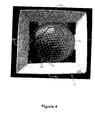
- Figure 4 is a top plan view of the first display container in the closed configuration and in combination with the game ball
- Figure 5 is another perspective view of the first display container in the closed configuration and in combination with the game ball.
- Figure 6 is a perspective view of the first display container in the closed configuration.
- Figures 7 and 8 are side elevational views of the first display container in the closed configuration.
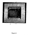
- Figure 9 is a top plan view of the first display container in the closed configuration.
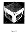
- Figure 10 is a perspective view of the first display container in an open configuration.
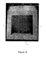
- Figures 11 and 12 are side elevational views of the first display container in the open configuration.
- Figure 13 is a plan view of an element that forms the first display container.
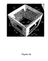
- Figure 14 is a perspective view of a second display container in a closed configuration.
- Figure 15 is a side elevational view of the second display container in the closed configuration.
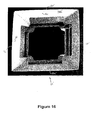
- Figure 16 is a top plan view of the second display container in the closed configuration.
- Figure 17 is a perspective view of a second display container in an open configuration.
- Figures 18 and 19 are side elevational views of the second display container in the open configuration.
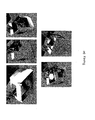
- Figure 20 illustrates a process for assembling the first display container.
- container 10 for receiving and displaying a game ball.
- container 10 is depicted in combination with a soccerball 100 in Figures 1-5 , other configurations of container 10 may be utilized to receive and display a variety of other game balls, including a basketball, volleyball, football, baseball, or softball, for example.
- Container 10 may also be utilized to receive and display a variety of other products, in addition to game balls. Accordingly, container 10 is disclosed in a configuration suitable for receiving and displaying soccerball 100 for purposes of example, and may also be utilized to receive and display a variety of other products.
- packaging for game balls may inhibit the consumers' ability to inspect game balls.
- loosely displaying game balls without packaging limits the ability of manufacturers to convey information regarding the game balls to the consumers, and loosely displaying game balls may not provide adequate protection to the game balls.
- Container 10, however, permits consumers to properly inspect soccerball 100 by exposing a significat area of soccerball 100.
- Container 10 also provides an area for information on soccerball 100 to be displayed, thereby providing the information to the consumers.
- container 10 imparts protection to soccerball 100 during transport and at a retail location.
- Container 10 is depicted in combination with soccerball 100 in Figures 1-5 .
- Figures 6-9 correspond with Figures 1-4 , but depict container 10 with soccerball 100 absent.
- Figures 1-9 depict container 10 in a closed configuration
- Figures 10-12 depict container 10 in an open configuration, which may be utilized to place soccerball 100 within container 10 or remove soccerball 100 from container 10.
- Figure 13 depicts container 10 in an unassembled configuration. That is, Figure 13 is a plan view of an element that forms container 10.
- container 10 may be formed from a single element of material, as in Figure 13 , some configurations of container 10 may be formed from two or more joined elements.
- a variety of materials may be utilized for display container 10, including cardboard, paper, various polymers, or combinations of these materials, for example. Accordingly, the element depicted in Figure 13 may be stamped or otherwise formed from a single cardboard element that is then folded and joined.
- Container 10 has a generally cubic shape that defines six sides 12a-12f and an interior void bounded by sides 12a-12f for receiving soccerball 100.
- Sides 12a and 12b respectively define apertures 14a and 14b through which soccerball 100 is visible.
- Sides 12c and 12d are not depicted as having apertures, which provides areas for information regarding soccerball 100 to be printed on the exterior of container 10.
- either of apertures 14a and 14b may be absent (i.e., the material of container 10 may extend across the areas of apertures 14a and 14b) or sides 12c and 12d may also include apertures.
- Sides 12e and 12f which respectively form a top and a bottom of container 10, also expose areas of soccerball 100. Accordingly, the configuration of container 10 in Figures 1-5 exposes soccerball 100 through four of the six sides 12a-12f.
- container 10 provides support to soccerball 100.
- the support is provided by various flaps 16a-16d that extend into the void in container 10 and contact soccerball 100.
- flaps 16a-16d that extend into the void in container 10 and contact soccerball 100.
- one of flaps 16a extends from an upper area of side 12a and is angled downward to contact soccerball 100
- another of flaps 16a extends from a lower area of side 12a and is angled upward to contact soccerball 100
- one of flaps 16b extends from an upper area of side 12b and is angled downward to contact soccerball 100
- another of flaps 16b extends from a lower area of side 12b and is angled upward to contact soccerball 100.
- each of sides 12c and 12d respectively have two flaps 16c and 16d that are angled downward and upward to contact soccerball 100.
- Each of flaps 16a-16d respectively have a protrusion 18a-18d that is approximately centered relative to sides of flaps 16a-16d and contacts soccerball 100.
- Protrusions 18a-18d extend outward from ends of flaps 16a-16d and have a concave configuration that contacts soccerball 100. That is, protrusions 18a-18d are shaped to have a curvature that is approximately equal to the curvature of soccerball 100. Accordingly, protrusions 18a-18d contact the surface of soccerball 100 along substantially all of the length of protrusions 18a-18d. In some configurations of container 10, protrusions 18a-18d may not be shaped to have a curvature that is approximately equal to the curvature of soccerball 100, or protrusions 18a-18d may be absent from flaps 16a-16d.
- End portions of flaps 16b and 16d also respectively form a pair of other protrusions 20b and 20d.
- end portions of flaps 16a and 16b respectively form a pair of slits 22a and 22c.
- protrusions 20b and 20d When folded inward, protrusions 20b and 20d extend into and mate with slits 22a and 22c to interlock flaps 16a-16d with each other.
- one of protrusions 20b from flap 16b is immediately adjacent one of slits 22a from flap 16a.
- protrusion 20b will extend into slit 22a to interlock flaps 16a and 16b. Similar concepts apply at other locations of container 10.
- Slits 22a and 22c may also have the configuration of elongate apertures in some configurations.
- FIG. 13 An element that forms container 10 is depicted in Figure 13 and the various sides 12a-12d, apertures 14a and 14b, flaps 16a-16d, protrusions 18a-18d, protrusions 20b and 20d, and slits 22a and 22c are depicted. Note, however, that the element does not actually include specific portions that form sides 12e and 12f.
- the element is folded along various fold lines 24 and (b) a joining flap 26 extending from an edge of side 12c is adhered or otherwise joined to side 12d, sides 12e and 12f are defined by the upper and lower edges of sides 12a-12d (i.e., the portions of sides 12a-12d with flaps 16a-16d).
- container 10 has a configuration suitable for receiving and displaying soccerball 100.
- container 10 may also be utilized to receive and display a variety of other types of game balls or other products.
- Advantages of the configuration of container 10 are that (a) consumers may inspect soccerball 100 through apertures 14a and 14b and through sides 12e and 12f, (b) sides 12c and 12d provide an area for information regarding soccerball 100 to be displayed, and (c) soccerball 100 is protected by container 10 during transport and at a retail location.
- Another advantage of container 10 relates to protrusions 18a-18d.
- protrusions 18a-18d are shaped to have a curvature that is approximately equal to the curvature of soccerball 100, and protrusions 18a-18d contact the surface of soccerball 100 along substantially all of the length of protrusions 18a-18d.
- This configuration limits the degree to which soccerball 100 rotates or otherwise moves during transport.
- logos or other information printed on soccerball 100 may remain visible to the consumer if placed within container 10 such that the logos are visible.
- An additional advantage of container 10 relates to the interaction between protrusions 20b and 20d and slits 22a and 22c.
- protrusions 20b and 20d When folded inward, protrusions 20b and 20d extend into and mate with slits 22a and 22c to interlock flaps 16a-16d with each other.
- flaps 16a-16d may be merely folded inward to interlock flaps 16a-16d and complete the assembly of container 10. That is, this configuration provides a relatively easy manner of securing soccerball 100 within container 10.
- FIG. 14-19 Another configuration is depicted in Figures 14-19 as container 10'.
- container 10' is suitable for receiving soccerball 100, other game balls, or a variety of other products.
- the primary elements of container 10' are various sides 12a'-12f', a pair of apertures 14a' and 14b', and eight flaps 16a'-16d'.
- Flaps 16a' and 16c' include various slits 22a' and 22c' that extend into various protrusions 20b' and 20d' on flaps 16b' and 16d' to interlock flaps 16a'-16d' with each other.
- Flaps 16a' and 16c' also include various wings 24a' and 24c' that fold inward to provide additional support for flaps 16a'-16d'.
- wings 24a'-d' may extend longitudinally past the sides of container 10'.
- the longitudinal edges/sides of flaps 16b' and 16d' may further be sloped to facilitate joining with flaps 16a' and 16c'.
- Wings 24a'-24d' may further extend in a lateral direction past a lateral edge of a remainder of flaps 16a' and 16c'.
- the longitudinal ends of flaps 16b' and 16d' may also protrude from the remainder of flaps 16b' and 16d' in a lateral direction.
- Each of wings 24a'-24d' may further include a crease between a portion extending beyond a side of container 10' and the remainder of the wing. Additionally or alternatively, a longitudinal edge of each wing of wings 24a'-24d' may be angled or sloped.
- FIG. 20 a method of assembling container 10 is depicted.
- the element depicted in Figure 13 is folded between sides 12a-12d such that joining flap 26 contacts side 12d, where joining flap 26 is adhered.
- Flaps 16a-16d adjacent side 12f are then folded inward so that protrusions 20b and 20d enter slits 22a and 22c.
- Soccerball 100 may then be placed within container 10 through side 12e, and flaps 16a-16d adjacent side 12e are then folded inward so that protrusions 20b and 20d enter slits 22a and 22c.
- soccerball 100 may be placed within container 10 through the side 12e after flaps 16a-16d adjacent side 12e are folded inward. This procedure secures soccerball 100 within container 10.
- two of flaps 16a-16d may be pressed downward.
- protrusions 20b and 20d are disengaged from slits 22a and 22c and each of flaps 16a-16d respectively extend adjacent to sides 12a-12d, thereby opening side 12e sufficiently for removal of soccerball 100. Accordingly, the relatively easy action of pressing downward on two of flaps 16a-16d is sufficient to remove soccerball 100 from container 10.
Landscapes
- Engineering & Computer Science (AREA)
- Mechanical Engineering (AREA)
- Cartons (AREA)
- Packaging Of Annular Or Rod-Shaped Articles, Wearing Apparel, Cassettes, Or The Like (AREA)
- Details Of Rigid Or Semi-Rigid Containers (AREA)
- Supports Or Holders For Household Use (AREA)
Abstract
Description
- Many athletic activities, particularly team sports, utilize one of a variety of game ball types. For example, the game of soccer utilizes a soccerball, whereas the game of basketball utilizes a basketball. Other types of game balls that are commonly utilized include footballs, volleyballs, baseballs, and softballs, for example. The suitability of a type of game ball for a particular athletic activity depends upon a variety of characteristics, including dimensions, shape, materials, and weight.
- When purchasing game balls, consumers generally prefer to inspect the game balls, which may include both a visual inspection and a tactile inspection (i.e., through touch) to ensure that the game balls possess the requisite characteristics. Moreover, inspection of the game balls permits the consumers to verify whether the game balls possess a requisite degree of quality, which is dependent upon workmanship and materials. Packaging, such a conventional box, may inhibit consumers' ability to inspect game balls. Accordingly, many manufacturers transport game balls to retail locations without packaging, and the game balls are displayed in bulk at the retail locations in a large bin or basket.
- One drawback to displaying game balls without packaging is that information regarding the game balls may not be provided to the consumers. For example, when game balls are loosely displayed in a large bin or basket, information on materials used in the game balls, specifications of the game ball, and approval from governing athletic organizations may not be coupled with the game balls for use by the consumers when selecting between models or manufacturers. Another drawback relates to protection of the game balls. That is, damage to the game balls may occur during transport or while on display at the retail location.
- A container for receiving and displaying a game ball or a variety of other products is disclosed. The container may permit consumers to inspect a game ball by exposing a significat area of the game ball. The container may also provide an area for information on the game ball to be displayed, therby providing the information to the consumers at a retail location. In addition, the container may impart protection to the game ball during transport and at the retail location.
- The container may include various flaps with protrusions shaped to have a curvature that is approximately equal to the curvature of the game ball. In addition to supporting the game ball, the protrusions may contact the surface of the game ball along substantially all of the length of the protrusions. This configuration limits the degree to which the game ball rotates or otherwise moves during transport. In addition, the flaps of the container may have other protrusions and slits that mate and interlock to join the flaps together. In this configuration, the flaps may be folded inward to interlock the flaps and complete assembly of the container. Similarly, the flaps may be pressed further inward to disengage the protrusions and slits for purposes of removing the game ball from the container.
- To gain an improved understanding of the advantages and features of novelty reference may be made to the following descriptive matter and accompanying drawings that describe and illustrate various embodiments and concepts related to the aspects of the invention.
- The foregoing Summary, as well as the following Detailed Description, will be better understood when read in conjunction with the accompanying drawings.
-
Figure 1 is a perspective view of a first display container in a closed configuration and in combination with a game ball. -
Figures 2 and3 are side elevational views of the first display container in the closed configuration and in combination with the game ball. -
Figure 4 is a top plan view of the first display container in the closed configuration and in combination with the game ball, -
Figure 5 is another perspective view of the first display container in the closed configuration and in combination with the game ball. -
Figure 6 is a perspective view of the first display container in the closed configuration. -
Figures 7 and8 are side elevational views of the first display container in the closed configuration. -
Figure 9 is a top plan view of the first display container in the closed configuration. -
Figure 10 is a perspective view of the first display container in an open configuration. -
Figures 11 and12 are side elevational views of the first display container in the open configuration. -
Figure 13 is a plan view of an element that forms the first display container. -
Figure 14 is a perspective view of a second display container in a closed configuration. -
Figure 15 is a side elevational view of the second display container in the closed configuration. -
Figure 16 is a top plan view of the second display container in the closed configuration. -
Figure 17 is a perspective view of a second display container in an open configuration. -
Figures 18 and19 are side elevational views of the second display container in the open configuration. -
Figure 20 illustrates a process for assembling the first display container. - The following discussion and accompanying figures disclose a
container 10 for receiving and displaying a game ball. Althoughcontainer 10 is depicted in combination with asoccerball 100 inFigures 1-5 , other configurations ofcontainer 10 may be utilized to receive and display a variety of other game balls, including a basketball, volleyball, football, baseball, or softball, for example.Container 10 may also be utilized to receive and display a variety of other products, in addition to game balls. Accordingly,container 10 is disclosed in a configuration suitable for receiving and displayingsoccerball 100 for purposes of example, and may also be utilized to receive and display a variety of other products. - As discussed in the Background section above, packaging for game balls may inhibit the consumers' ability to inspect game balls. Furthermore, loosely displaying game balls without packaging limits the ability of manufacturers to convey information regarding the game balls to the consumers, and loosely displaying game balls may not provide adequate protection to the game balls.
Container 10, however, permits consumers to properly inspectsoccerball 100 by exposing a significat area ofsoccerball 100.Container 10 also provides an area for information onsoccerball 100 to be displayed, thereby providing the information to the consumers. In addition,container 10 imparts protection tosoccerball 100 during transport and at a retail location. -
Container 10 is depicted in combination withsoccerball 100 inFigures 1-5 .Figures 6-9 correspond withFigures 1-4 , but depictcontainer 10 withsoccerball 100 absent. WhereasFigures 1-9 depictcontainer 10 in a closed configuration,Figures 10-12 depictcontainer 10 in an open configuration, which may be utilized to placesoccerball 100 withincontainer 10 or removesoccerball 100 fromcontainer 10. In addition,Figure 13 depictscontainer 10 in an unassembled configuration. That is,Figure 13 is a plan view of an element that formscontainer 10. Althoughcontainer 10 may be formed from a single element of material, as inFigure 13 , some configurations ofcontainer 10 may be formed from two or more joined elements. A variety of materials may be utilized fordisplay container 10, including cardboard, paper, various polymers, or combinations of these materials, for example. Accordingly, the element depicted inFigure 13 may be stamped or otherwise formed from a single cardboard element that is then folded and joined. -
Container 10 has a generally cubic shape that defines sixsides 12a-12f and an interior void bounded bysides 12a-12f for receivingsoccerball 100.Sides 12a and 12b respectively defineapertures 14a and 14b through whichsoccerball 100 is visible. Sides 12c and 12d are not depicted as having apertures, which provides areas forinformation regarding soccerball 100 to be printed on the exterior ofcontainer 10. In further configurations ofcontainer 10, either ofapertures 14a and 14b may be absent (i.e., the material ofcontainer 10 may extend across the areas ofapertures 14a and 14b) or sides 12c and 12d may also include apertures.Sides 12e and 12f, which respectively form a top and a bottom ofcontainer 10, also expose areas ofsoccerball 100. Accordingly, the configuration ofcontainer 10 inFigures 1-5 exposes soccerball 100 through four of the sixsides 12a-12f. - In addition to exposing portions of
soccerball 100,container 10 provides support to soccerball 100. The support is provided byvarious flaps 16a-16d that extend into the void incontainer 10 andcontact soccerball 100. For example, one offlaps 16a extends from an upper area ofside 12a and is angled downward to contactsoccerball 100, and another offlaps 16a extends from a lower area ofside 12a and is angled upward to contactsoccerball 100. Similarly, one offlaps 16b extends from an upper area of side 12b and is angled downward to contactsoccerball 100, and another offlaps 16b extends from a lower area of side 12b and is angled upward to contactsoccerball 100. As withsides 12a and 12b, each of sides 12c and 12d respectively have twoflaps soccerball 100. - Each of
flaps 16a-16d respectively have a protrusion 18a-18d that is approximately centered relative to sides offlaps 16a-16d and contacts soccerball 100. Protrusions 18a-18d extend outward from ends offlaps 16a-16d and have a concave configuration that contacts soccerball 100. That is, protrusions 18a-18d are shaped to have a curvature that is approximately equal to the curvature ofsoccerball 100. Accordingly, protrusions 18a-18d contact the surface ofsoccerball 100 along substantially all of the length of protrusions 18a-18d. In some configurations ofcontainer 10, protrusions 18a-18d may not be shaped to have a curvature that is approximately equal to the curvature ofsoccerball 100, or protrusions 18a-18d may be absent fromflaps 16a-16d. - End portions of
flaps other protrusions 20b and 20d. Similarly, end portions offlaps slits protrusions 20b and 20d extend into and mate withslits flaps 16a-16d with each other. Referring specifically toFigure 10 , one ofprotrusions 20b fromflap 16b is immediately adjacent one ofslits 22a fromflap 16a. When flaps 16a and 16b are folded inward,protrusion 20b will extend intoslit 22a to interlockflaps container 10.Slits - An element that forms
container 10 is depicted inFigure 13 and thevarious sides 12a-12d,apertures 14a and 14b, flaps 16a-16d, protrusions 18a-18d,protrusions 20b and 20d, and slits 22a and 22c are depicted. Note, however, that the element does not actually include specific portions that form sides 12e and 12f. When (a) the element is folded alongvarious fold lines 24 and (b) a joiningflap 26 extending from an edge of side 12c is adhered or otherwise joined to side 12d, sides 12e and 12f are defined by the upper and lower edges ofsides 12a-12d (i.e., the portions ofsides 12a-12d withflaps 16a-16d). - Based upon the above discussion,
container 10 has a configuration suitable for receiving and displayingsoccerball 100. In other configurations,container 10 may also be utilized to receive and display a variety of other types of game balls or other products. Advantages of the configuration ofcontainer 10 are that (a) consumers may inspect soccerball 100 throughapertures 14a and 14b and throughsides 12e and 12f, (b) sides 12c and 12d provide an area forinformation regarding soccerball 100 to be displayed, and (c) soccerball 100 is protected bycontainer 10 during transport and at a retail location. Another advantage ofcontainer 10 relates to protrusions 18a-18d. As discussed, protrusions 18a-18d are shaped to have a curvature that is approximately equal to the curvature ofsoccerball 100, and protrusions 18a-18d contact the surface ofsoccerball 100 along substantially all of the length of protrusions 18a-18d. This configuration limits the degree to whichsoccerball 100 rotates or otherwise moves during transport. At the retail location, therefore, logos or other information printed onsoccerball 100 may remain visible to the consumer if placed withincontainer 10 such that the logos are visible. An additional advantage ofcontainer 10 relates to the interaction betweenprotrusions 20b and 20d and slits 22a and 22c. When folded inward,protrusions 20b and 20d extend into and mate withslits flaps 16a-16d with each other. In this configuration, flaps 16a-16d may be merely folded inward to interlockflaps 16a-16d and complete the assembly ofcontainer 10. That is, this configuration provides a relatively easy manner of securingsoccerball 100 withincontainer 10. - Another configuration is depicted in
Figures 14-19 as container 10'. As withcontainer 10, container 10' is suitable for receivingsoccerball 100, other game balls, or a variety of other products. The primary elements of container 10' arevarious sides 12a'-12f', a pair ofapertures 14a' and 14b', and eightflaps 16a'-16d'.Flaps 16a' and 16c' includevarious slits 22a' and 22c' that extend intovarious protrusions 20b' and 20d' onflaps 16b' and 16d' to interlockflaps 16a'-16d' with each other.Flaps 16a' and 16c' also includevarious wings 24a' and 24c' that fold inward to provide additional support forflaps 16a'-16d'. In one or more configurations,wings 24a'-d' may extend longitudinally past the sides of container 10'. The longitudinal edges/sides offlaps 16b' and 16d' may further be sloped to facilitate joining withflaps 16a' and 16c'.Wings 24a'-24d' may further extend in a lateral direction past a lateral edge of a remainder offlaps 16a' and 16c'. Similarly, the longitudinal ends offlaps 16b' and 16d' may also protrude from the remainder offlaps 16b' and 16d' in a lateral direction. Each ofwings 24a'-24d' may further include a crease between a portion extending beyond a side of container 10' and the remainder of the wing. Additionally or alternatively, a longitudinal edge of each wing ofwings 24a'-24d' may be angled or sloped. - With reference to
Figure 20 , a method of assemblingcontainer 10 is depicted. Initially, the element depicted inFigure 13 is folded betweensides 12a-12d such that joiningflap 26 contacts side 12d, where joiningflap 26 is adhered.Flaps 16a-16d adjacent side 12f are then folded inward so thatprotrusions 20b and 20d enterslits Soccerball 100 may then be placed withincontainer 10 throughside 12e, and flaps 16a-16dadjacent side 12e are then folded inward so thatprotrusions 20b and 20d enterslits container 10 through theside 12e afterflaps 16a-16dadjacent side 12e are folded inward. This procedure secures soccerball 100 withincontainer 10. - In order to remove soccerball 100 from
container 10, two offlaps 16a-16d may be pressed downward. By pressing two offlaps 16a-16d further inward,protrusions 20b and 20d are disengaged fromslits flaps 16a-16d respectively extend adjacent tosides 12a-12d, thereby openingside 12e sufficiently for removal ofsoccerball 100. Accordingly, the relatively easy action of pressing downward on two offlaps 16a-16d is sufficient to remove soccerball 100 fromcontainer 10. - The invention is disclosed above and in the accompanying drawings with reference to a variety of embodiments. The purpose served by the disclosure, however, is to provide an example of the various features and concepts related to aspects of the invention, not to limit the scope of aspects of the invention. One skilled in the relevant art will recognize that numerous variations and modifications may be made to the embodiments described above without departing from the scope of the invention, as defined herein.
-
- 1. A display structure comprising:
- a first flap of a plurality of flaps, wherein the first flap includes a protrusion extending from a lateral edge of the first flap, wherein the protrusion is configured to contact a product contained within the display structure and wherein the plurality of flaps are configured to form a first side of the structure, the first side including an aperture.
- 2. The display structure of clause 1, wherein the first flap is flexible along a crease defined by a second lateral edge of the first flap where the first flap joins a second side of the display structure.
- 3. The display structure of clause 1, wherein the first side comprises at least four flaps configured to form a rectangular aperture.
- 4. The display structure of clause 1, wherein the protrusion is arcuate in shape.
- 5. The display structure of clause 1, wherein the plurality of flaps includes a second flap, the second flap including a second protrusion extending from a third lateral side of the second flap and a third protrusion extending longitudinally from a first longitudinal edge of the second flap.
- 6. The display structure of clause 5, wherein the first flap further includes a slit in a first longitudinal end portion of the first flap, the slit configured to receive the third protrusion of the second flap.
- 7. The display structure of clause 6, wherein the first flap and the second flap are substantially perpendicular to each other.
- 8. The display structure of clause 1, wherein the first flap is joined to a side panel, the side panel configured to form a second side of the display structure.
- 9. A structure configurable to form a display apparatus, the structure comprising:
- a first panel comprising a first flap, the first flap including a protrusion extending longitudinally from a longitudinal side of the first flap; and
- a second panel comprising a second flap, the second flap including a slit in a first end portion of the second flap, wherein the slit is configured to receive at least a portion of the protrusion of the first flap.
- 10. The structure of clause 9, wherein the slit is angled relative to a vertical axis extending from a first lateral end to a second lateral end of the second flap.
- 11. The structure of clause 9, wherein the second flap further includes a crease extending from an interior edge of the slit.
- 12. The structure of clause 9, wherein the second flap includes at least two slits.
- 13. The structure of clause 9, wherein the first flap includes a second protrusion extending longitudinally from a second longitudinal side of the first flap.
- 14. The structure of clause 9, further comprising:
- a third panel comprising a third flap, the third flap including a second protrusion extending longitudinally from a first longitudinal side of the third flap; and
- a fourth panel comprising a fourth flap, the fourth flap including a second slit in a first end portion of the fourth flap, wherein the second slit is configured to receive the second protrusion of the third flap.
- 15. The structure of
clause 14, wherein the first flap and the third flap are substantially parallel and wherein the second flap and the fourth flap are substantially parallel. - 16. The structure of clause 9, wherein the second flap further includes a second protrusion extending in a lateral direction from a lateral edge of the second flap.
- 17. The structure of
clause 16, wherein the second protrusion is centrally located along the lateral edge. - 18. The structure of
clause 16, wherein the second protrusion is arcuate in shape. - 19. The structure of clause 9, wherein the side of the first flap from which the protrusion extends is sloped.
- 20. A structure configurable to form a container comprising:
- a first panel including a first flap, the first flap having a wing extending from a longitudinal end of the first flap and wherein the longitudinal end includes an enclosed slot configured to receive a portion of a second flap; and
- a second panel including the second flap, wherein the second flap includes a protrusion configured for insertion into the enclosed slot of the first flap, and wherein the first flap and the second flap are configured to form a side of the structure, the side having an aperture through which a contained product is visible.
- 21. The structure of clause 20, wherein a second longitudinal end of the second flap is sloped.
- 22. The structure of clause 20, wherein the second longitudinal end of the second flap protrudes laterally from a remainder of the second flap.
- 23. The structure of clause 20, wherein the first panel includes a first surface having an aperture and the second panel includes a second surface void of apertures.
- 24. The structure of clause 20, wherein the first wing is configured to flex inward toward an interior of the container.
- 25. The structure of clause 20, wherein the first panel includes at least two flaps, and each of the at least two flaps includes at least two wings.
- 26. The structure of clause 25, wherein a first wing and a second wing of the first flap extend longitudinally from the first flap in opposite directions.
Claims (7)
- A structure configurable to form a container for containing a product comprising:a first panel including a first flap having a wing extending from a longitudinal end of the first flap and wherein the longitudinal end includes an enclosed slot configured to receive a portion of a second flap; anda second panel including the second flap, wherein the second flap includes a first protrusion configured for insertion into the enclosed slot of the first flap, and wherein the first flap and the second flap are configured to form a side of the structure, the side having an aperture through which the contained product is visible.
- The structure of claim 1, wherein a second longitudinal end of the second flap is sloped.
- The structure of claim 1, wherein the second longitudinal end of the second flap protrudes laterally from a remainder of the second flap.
- The structure of claim 1, wherein the first panel includes a first surface having a second aperture and the second panel includes a second surface void of apertures.
- The structure of claim 1, wherein the first wing is configured to flex inward toward an interior of the container.
- The structure of claim 1, wherein the first panel includes at least two flaps, and each of the at least two flaps includes at least two wings.
- The structure of claim 6, wherein a first wing and a second wing of the first flap extend longitudinally from the first flap in opposite directions.
Applications Claiming Priority (3)
| Application Number | Priority Date | Filing Date | Title |
|---|---|---|---|
| US81220006P | 2006-06-09 | 2006-06-09 | |
| US11/759,844 US7938259B2 (en) | 2006-06-09 | 2007-06-07 | Display container |
| EP07809461A EP2027027B1 (en) | 2006-06-09 | 2007-06-08 | Display container |
Related Parent Applications (1)
| Application Number | Title | Priority Date | Filing Date |
|---|---|---|---|
| EP07809461.2 Division | 2007-06-08 |
Publications (2)
| Publication Number | Publication Date |
|---|---|
| EP2261127A1 true EP2261127A1 (en) | 2010-12-15 |
| EP2261127B1 EP2261127B1 (en) | 2012-02-15 |
Family
ID=38739462
Family Applications (2)
| Application Number | Title | Priority Date | Filing Date |
|---|---|---|---|
| EP10176659A Active EP2261127B1 (en) | 2006-06-09 | 2007-06-08 | Structure to form a container |
| EP07809461A Active EP2027027B1 (en) | 2006-06-09 | 2007-06-08 | Display container |
Family Applications After (1)
| Application Number | Title | Priority Date | Filing Date |
|---|---|---|---|
| EP07809461A Active EP2027027B1 (en) | 2006-06-09 | 2007-06-08 | Display container |
Country Status (5)
| Country | Link |
|---|---|
| US (1) | US7938259B2 (en) |
| EP (2) | EP2261127B1 (en) |
| CN (1) | CN201367155Y (en) |
| AT (2) | ATE517817T1 (en) |
| WO (1) | WO2007146240A2 (en) |
Families Citing this family (17)
| Publication number | Priority date | Publication date | Assignee | Title |
|---|---|---|---|---|
| USD752994S1 (en) | 2015-03-17 | 2016-04-05 | Nike, Inc. | Packaging box with ball |
| US9643747B2 (en) | 2015-03-17 | 2017-05-09 | Nike, Inc. | Display packaging |
| USD751418S1 (en) | 2015-03-17 | 2016-03-15 | Nike, Inc. | Packaging box with ball |
| USD751417S1 (en) | 2015-03-17 | 2016-03-15 | Nike, Inc. | Packaging box with ball |
| USD750972S1 (en) | 2015-03-17 | 2016-03-08 | Nike, Inc. | Packaging box with ball |
| USD806531S1 (en) * | 2016-04-28 | 2018-01-02 | Nike, Inc. | Packaging box with ball |
| USD785450S1 (en) * | 2016-05-24 | 2017-05-02 | Franklin Sports, Inc. | Sports ball display carton |
| JP6849541B2 (en) * | 2017-06-14 | 2021-03-24 | 金子ホールディングス株式会社 | Cardboard packaging box |
| USD874722S1 (en) * | 2017-07-13 | 2020-02-04 | Paris Presents Incorporated | Combined makeup sponge and stand |
| CN112520166B (en) * | 2020-12-02 | 2024-11-15 | 东莞市美盈森环保科技有限公司 | Spherical product cushioning packaging box |
| WO2023034199A1 (en) * | 2021-09-01 | 2023-03-09 | General Printing & Design, Inc. | Display package for an inflatable ball |
| CN118234549A (en) * | 2021-09-01 | 2024-06-21 | 通用印刷设计公司 | Display packaging for inflatable balls |
| USD988443S1 (en) * | 2021-10-22 | 2023-06-06 | General Printing & Design, Inc. | Packaged inflatable ball |
| USD970354S1 (en) * | 2022-02-02 | 2022-11-22 | General Printing & Design, Inc. | Packaged inflatable ball |
| JP7826840B2 (en) * | 2022-05-31 | 2026-03-10 | Toppanホールディングス株式会社 | Cardboard packaging boxes, blanks, and intermediate packaging boxes |
| US11767142B1 (en) * | 2022-07-25 | 2023-09-26 | Gregg Gorski | Product display package |
| USD1026642S1 (en) * | 2022-07-25 | 2024-05-14 | Gregg Gorski | Product package |
Citations (6)
| Publication number | Priority date | Publication date | Assignee | Title |
|---|---|---|---|---|
| BE514412A (en) * | ||||
| GB1222549A (en) * | 1968-05-15 | 1971-02-17 | Mardon Son & Hall Ltd | Display pack and blank therefor |
| US4194679A (en) * | 1978-11-06 | 1980-03-25 | Champion International Corporation | Self-locking container |
| GB2202205A (en) * | 1987-03-19 | 1988-09-21 | Vernon Packaging Ltd | Carton |
| US5139196A (en) * | 1991-07-02 | 1992-08-18 | International Paper Company | Paperboard container |
| US20040069842A1 (en) * | 2002-10-15 | 2004-04-15 | Georgia-Pacific Corporation | Container with locking flanges |
Family Cites Families (16)
| Publication number | Priority date | Publication date | Assignee | Title |
|---|---|---|---|---|
| GB206764A (en) | 1923-02-08 | 1923-11-15 | Rowland Hunt | Improved box or carton for electric lamps and other fragile articles |
| US2205341A (en) * | 1936-04-27 | 1940-06-18 | Bank Of The Manhattan Company | Merchandising package |
| US3337033A (en) * | 1965-03-22 | 1967-08-22 | Riegel Paper Corp | Carton |
| US3455498A (en) * | 1967-10-16 | 1969-07-15 | Intern Graphics & Packaging Co | Disposable container |
| US3539091A (en) * | 1968-11-13 | 1970-11-10 | Container Corp | Display carton for flood lamps |
| US3734397A (en) * | 1971-03-25 | 1973-05-22 | Rexham Corp | Support and display carton for parabolic lamp |
| US3987893A (en) * | 1976-01-22 | 1976-10-26 | Champion International Corporation | Display carton and blank therefor |
| US4162008A (en) * | 1978-04-28 | 1979-07-24 | Westinghouse Electric Corp. | Shipping and display carton for an electric lamp or similar article, and resulting package |
| US4452355A (en) * | 1982-09-16 | 1984-06-05 | Champion International Corporation | Display carton |
| US4717022A (en) * | 1984-12-24 | 1988-01-05 | General Electric Company | Octagonal-shaped shipping container |
| US6199692B1 (en) * | 1996-05-10 | 2001-03-13 | Van Ness Plastic Molding Inc. | Reduced material box design for round objects |
| US5881885A (en) * | 1997-02-27 | 1999-03-16 | Oddzon Products, Inc. | Article packaging |
| US6036010A (en) | 1998-06-10 | 2000-03-14 | Sports Licensing, Inc. | Game ball display box and method for assembling same |
| US6568528B2 (en) * | 2000-12-29 | 2003-05-27 | Inland Paperboard And Packaging, Inc. | Display container |
| US6644473B2 (en) * | 2001-09-24 | 2003-11-11 | Smurfit-Stone Container Corporation | Carton for holding and displaying balls |
| USD532686S1 (en) * | 2005-09-09 | 2006-11-28 | Horizon Group - Usa, Inc. | Display package |
-
2007
- 2007-06-07 US US11/759,844 patent/US7938259B2/en active Active
- 2007-06-08 WO PCT/US2007/013704 patent/WO2007146240A2/en not_active Ceased
- 2007-06-08 CN CNU2007900000791U patent/CN201367155Y/en not_active Expired - Lifetime
- 2007-06-08 AT AT07809461T patent/ATE517817T1/en not_active IP Right Cessation
- 2007-06-08 EP EP10176659A patent/EP2261127B1/en active Active
- 2007-06-08 EP EP07809461A patent/EP2027027B1/en active Active
- 2007-06-08 AT AT10176659T patent/ATE545597T1/en active
Patent Citations (6)
| Publication number | Priority date | Publication date | Assignee | Title |
|---|---|---|---|---|
| BE514412A (en) * | ||||
| GB1222549A (en) * | 1968-05-15 | 1971-02-17 | Mardon Son & Hall Ltd | Display pack and blank therefor |
| US4194679A (en) * | 1978-11-06 | 1980-03-25 | Champion International Corporation | Self-locking container |
| GB2202205A (en) * | 1987-03-19 | 1988-09-21 | Vernon Packaging Ltd | Carton |
| US5139196A (en) * | 1991-07-02 | 1992-08-18 | International Paper Company | Paperboard container |
| US20040069842A1 (en) * | 2002-10-15 | 2004-04-15 | Georgia-Pacific Corporation | Container with locking flanges |
Also Published As
| Publication number | Publication date |
|---|---|
| US7938259B2 (en) | 2011-05-10 |
| ATE545597T1 (en) | 2012-03-15 |
| ATE517817T1 (en) | 2011-08-15 |
| CN201367155Y (en) | 2009-12-23 |
| WO2007146240A3 (en) | 2008-05-15 |
| US20080047858A1 (en) | 2008-02-28 |
| EP2261127B1 (en) | 2012-02-15 |
| EP2027027B1 (en) | 2011-07-27 |
| EP2027027A2 (en) | 2009-02-25 |
| WO2007146240A2 (en) | 2007-12-21 |
Similar Documents
| Publication | Publication Date | Title |
|---|---|---|
| US7938259B2 (en) | Display container | |
| US3987893A (en) | Display carton and blank therefor | |
| US3815735A (en) | Carton | |
| US5104124A (en) | Collapsible game usable as a promotional device | |
| US5246161A (en) | Box with collectible card | |
| US4181220A (en) | Display packaging insert | |
| US6036010A (en) | Game ball display box and method for assembling same | |
| CN102344001A (en) | Open packaging | |
| WO2009061505A1 (en) | Carrier for beverage and/or food | |
| US20250121980A1 (en) | Convertible carton game system | |
| US20070227943A1 (en) | Product packaging | |
| KR200445759Y1 (en) | Completion type packaging box | |
| WO2014193683A1 (en) | Reconfigurable golf ball container | |
| US20080296841A1 (en) | Container including an interactive game board and blank for making the same | |
| US6209780B1 (en) | Quiz game french fry scoop | |
| US20070057463A1 (en) | System and method for providing a portable game | |
| US20160272358A1 (en) | Display Packaging | |
| US20250115415A1 (en) | Display Package for an Inflatable Ball | |
| EP3271257B1 (en) | Display packaging | |
| CN219215813U (en) | Folding storage barrel for shuttlecock | |
| EP3919144A1 (en) | Travel and outdoor playmat | |
| CN211520224U (en) | Portable packing box | |
| WO2013041116A1 (en) | System comprising a transport box and/or sales box for footwear and a bag | |
| CN219440670U (en) | Box type toy | |
| JP4169419B2 (en) | Spherical fruit and vegetable partition material |
Legal Events
| Date | Code | Title | Description |
|---|---|---|---|
| PUAI | Public reference made under article 153(3) epc to a published international application that has entered the european phase |
Free format text: ORIGINAL CODE: 0009012 |
|
| AC | Divisional application: reference to earlier application |
Ref document number: 2027027 Country of ref document: EP Kind code of ref document: P |
|
| AK | Designated contracting states |
Kind code of ref document: A1 Designated state(s): AT BE BG CH CY CZ DE DK EE ES FI FR GB GR HU IE IS IT LI LT LU LV MC MT NL PL PT RO SE SI SK TR |
|
| 17P | Request for examination filed |
Effective date: 20110606 |
|
| GRAP | Despatch of communication of intention to grant a patent |
Free format text: ORIGINAL CODE: EPIDOSNIGR1 |
|
| RIC1 | Information provided on ipc code assigned before grant |
Ipc: B65D 5/50 20060101AFI20110808BHEP |
|
| RTI1 | Title (correction) |
Free format text: STRUCTURE TO FORM A CONTAINER |
|
| GRAS | Grant fee paid |
Free format text: ORIGINAL CODE: EPIDOSNIGR3 |
|
| GRAA | (expected) grant |
Free format text: ORIGINAL CODE: 0009210 |
|
| AC | Divisional application: reference to earlier application |
Ref document number: 2027027 Country of ref document: EP Kind code of ref document: P |
|
| AK | Designated contracting states |
Kind code of ref document: B1 Designated state(s): AT BE BG CH CY CZ DE DK EE ES FI FR GB GR HU IE IS IT LI LT LU LV MC MT NL PL PT RO SE SI SK TR |
|
| REG | Reference to a national code |
Ref country code: CH Ref legal event code: EP Ref country code: GB Ref legal event code: FG4D |
|
| REG | Reference to a national code |
Ref country code: IE Ref legal event code: FG4D |
|
| REG | Reference to a national code |
Ref country code: AT Ref legal event code: REF Ref document number: 545597 Country of ref document: AT Kind code of ref document: T Effective date: 20120315 |
|
| REG | Reference to a national code |
Ref country code: DE Ref legal event code: R096 Ref document number: 602007020778 Country of ref document: DE Effective date: 20120412 |
|
| REG | Reference to a national code |
Ref country code: NL Ref legal event code: VDEP Effective date: 20120215 |
|
| LTIE | Lt: invalidation of european patent or patent extension |
Effective date: 20120215 |
|
| PG25 | Lapsed in a contracting state [announced via postgrant information from national office to epo] |
Ref country code: IS Free format text: LAPSE BECAUSE OF FAILURE TO SUBMIT A TRANSLATION OF THE DESCRIPTION OR TO PAY THE FEE WITHIN THE PRESCRIBED TIME-LIMIT Effective date: 20120615 Ref country code: LT Free format text: LAPSE BECAUSE OF FAILURE TO SUBMIT A TRANSLATION OF THE DESCRIPTION OR TO PAY THE FEE WITHIN THE PRESCRIBED TIME-LIMIT Effective date: 20120215 Ref country code: NL Free format text: LAPSE BECAUSE OF FAILURE TO SUBMIT A TRANSLATION OF THE DESCRIPTION OR TO PAY THE FEE WITHIN THE PRESCRIBED TIME-LIMIT Effective date: 20120215 |
|
| PG25 | Lapsed in a contracting state [announced via postgrant information from national office to epo] |
Ref country code: PL Free format text: LAPSE BECAUSE OF FAILURE TO SUBMIT A TRANSLATION OF THE DESCRIPTION OR TO PAY THE FEE WITHIN THE PRESCRIBED TIME-LIMIT Effective date: 20120215 Ref country code: LV Free format text: LAPSE BECAUSE OF FAILURE TO SUBMIT A TRANSLATION OF THE DESCRIPTION OR TO PAY THE FEE WITHIN THE PRESCRIBED TIME-LIMIT Effective date: 20120215 Ref country code: FI Free format text: LAPSE BECAUSE OF FAILURE TO SUBMIT A TRANSLATION OF THE DESCRIPTION OR TO PAY THE FEE WITHIN THE PRESCRIBED TIME-LIMIT Effective date: 20120215 Ref country code: GR Free format text: LAPSE BECAUSE OF FAILURE TO SUBMIT A TRANSLATION OF THE DESCRIPTION OR TO PAY THE FEE WITHIN THE PRESCRIBED TIME-LIMIT Effective date: 20120516 Ref country code: BE Free format text: LAPSE BECAUSE OF FAILURE TO SUBMIT A TRANSLATION OF THE DESCRIPTION OR TO PAY THE FEE WITHIN THE PRESCRIBED TIME-LIMIT Effective date: 20120215 Ref country code: PT Free format text: LAPSE BECAUSE OF FAILURE TO SUBMIT A TRANSLATION OF THE DESCRIPTION OR TO PAY THE FEE WITHIN THE PRESCRIBED TIME-LIMIT Effective date: 20120615 |
|
| REG | Reference to a national code |
Ref country code: AT Ref legal event code: MK05 Ref document number: 545597 Country of ref document: AT Kind code of ref document: T Effective date: 20120215 |
|
| PG25 | Lapsed in a contracting state [announced via postgrant information from national office to epo] |
Ref country code: CY Free format text: LAPSE BECAUSE OF FAILURE TO SUBMIT A TRANSLATION OF THE DESCRIPTION OR TO PAY THE FEE WITHIN THE PRESCRIBED TIME-LIMIT Effective date: 20120215 |
|
| PG25 | Lapsed in a contracting state [announced via postgrant information from national office to epo] |
Ref country code: RO Free format text: LAPSE BECAUSE OF FAILURE TO SUBMIT A TRANSLATION OF THE DESCRIPTION OR TO PAY THE FEE WITHIN THE PRESCRIBED TIME-LIMIT Effective date: 20120215 Ref country code: EE Free format text: LAPSE BECAUSE OF FAILURE TO SUBMIT A TRANSLATION OF THE DESCRIPTION OR TO PAY THE FEE WITHIN THE PRESCRIBED TIME-LIMIT Effective date: 20120215 Ref country code: SE Free format text: LAPSE BECAUSE OF FAILURE TO SUBMIT A TRANSLATION OF THE DESCRIPTION OR TO PAY THE FEE WITHIN THE PRESCRIBED TIME-LIMIT Effective date: 20120215 Ref country code: CZ Free format text: LAPSE BECAUSE OF FAILURE TO SUBMIT A TRANSLATION OF THE DESCRIPTION OR TO PAY THE FEE WITHIN THE PRESCRIBED TIME-LIMIT Effective date: 20120215 Ref country code: SI Free format text: LAPSE BECAUSE OF FAILURE TO SUBMIT A TRANSLATION OF THE DESCRIPTION OR TO PAY THE FEE WITHIN THE PRESCRIBED TIME-LIMIT Effective date: 20120215 Ref country code: DK Free format text: LAPSE BECAUSE OF FAILURE TO SUBMIT A TRANSLATION OF THE DESCRIPTION OR TO PAY THE FEE WITHIN THE PRESCRIBED TIME-LIMIT Effective date: 20120215 |
|
| PG25 | Lapsed in a contracting state [announced via postgrant information from national office to epo] |
Ref country code: IT Free format text: LAPSE BECAUSE OF FAILURE TO SUBMIT A TRANSLATION OF THE DESCRIPTION OR TO PAY THE FEE WITHIN THE PRESCRIBED TIME-LIMIT Effective date: 20120215 Ref country code: SK Free format text: LAPSE BECAUSE OF FAILURE TO SUBMIT A TRANSLATION OF THE DESCRIPTION OR TO PAY THE FEE WITHIN THE PRESCRIBED TIME-LIMIT Effective date: 20120215 |
|
| PLBE | No opposition filed within time limit |
Free format text: ORIGINAL CODE: 0009261 |
|
| STAA | Information on the status of an ep patent application or granted ep patent |
Free format text: STATUS: NO OPPOSITION FILED WITHIN TIME LIMIT |
|
| 26N | No opposition filed |
Effective date: 20121116 |
|
| PG25 | Lapsed in a contracting state [announced via postgrant information from national office to epo] |
Ref country code: AT Free format text: LAPSE BECAUSE OF FAILURE TO SUBMIT A TRANSLATION OF THE DESCRIPTION OR TO PAY THE FEE WITHIN THE PRESCRIBED TIME-LIMIT Effective date: 20120215 Ref country code: MC Free format text: LAPSE BECAUSE OF NON-PAYMENT OF DUE FEES Effective date: 20120630 |
|
| REG | Reference to a national code |
Ref country code: CH Ref legal event code: PL |
|
| REG | Reference to a national code |
Ref country code: CH Ref legal event code: PL |
|
| REG | Reference to a national code |
Ref country code: DE Ref legal event code: R097 Ref document number: 602007020778 Country of ref document: DE Effective date: 20121116 |
|
| REG | Reference to a national code |
Ref country code: IE Ref legal event code: MM4A |
|
| PG25 | Lapsed in a contracting state [announced via postgrant information from national office to epo] |
Ref country code: CH Free format text: LAPSE BECAUSE OF NON-PAYMENT OF DUE FEES Effective date: 20120630 Ref country code: LI Free format text: LAPSE BECAUSE OF NON-PAYMENT OF DUE FEES Effective date: 20120630 Ref country code: IE Free format text: LAPSE BECAUSE OF NON-PAYMENT OF DUE FEES Effective date: 20120608 Ref country code: ES Free format text: LAPSE BECAUSE OF FAILURE TO SUBMIT A TRANSLATION OF THE DESCRIPTION OR TO PAY THE FEE WITHIN THE PRESCRIBED TIME-LIMIT Effective date: 20120526 |
|
| PG25 | Lapsed in a contracting state [announced via postgrant information from national office to epo] |
Ref country code: MT Free format text: LAPSE BECAUSE OF FAILURE TO SUBMIT A TRANSLATION OF THE DESCRIPTION OR TO PAY THE FEE WITHIN THE PRESCRIBED TIME-LIMIT Effective date: 20120215 Ref country code: BG Free format text: LAPSE BECAUSE OF FAILURE TO SUBMIT A TRANSLATION OF THE DESCRIPTION OR TO PAY THE FEE WITHIN THE PRESCRIBED TIME-LIMIT Effective date: 20120515 |
|
| REG | Reference to a national code |
Ref country code: DE Ref legal event code: R082 Ref document number: 602007020778 Country of ref document: DE Representative=s name: KOTITSCHKE & HEURUNG PARTNERSCHAFT MBB PATENT-, DE |
|
| PG25 | Lapsed in a contracting state [announced via postgrant information from national office to epo] |
Ref country code: TR Free format text: LAPSE BECAUSE OF FAILURE TO SUBMIT A TRANSLATION OF THE DESCRIPTION OR TO PAY THE FEE WITHIN THE PRESCRIBED TIME-LIMIT Effective date: 20120215 |
|
| PG25 | Lapsed in a contracting state [announced via postgrant information from national office to epo] |
Ref country code: LU Free format text: LAPSE BECAUSE OF NON-PAYMENT OF DUE FEES Effective date: 20120608 |
|
| REG | Reference to a national code |
Ref country code: GB Ref legal event code: 732E Free format text: REGISTERED BETWEEN 20140626 AND 20140702 |
|
| PG25 | Lapsed in a contracting state [announced via postgrant information from national office to epo] |
Ref country code: HU Free format text: LAPSE BECAUSE OF FAILURE TO SUBMIT A TRANSLATION OF THE DESCRIPTION OR TO PAY THE FEE WITHIN THE PRESCRIBED TIME-LIMIT Effective date: 20070608 |
|
| REG | Reference to a national code |
Ref country code: DE Ref legal event code: R082 Ref document number: 602007020778 Country of ref document: DE Representative=s name: KOTITSCHKE & HEURUNG PARTNERSCHAFT MBB PATENT-, DE |
|
| REG | Reference to a national code |
Ref country code: DE Ref legal event code: R082 Ref document number: 602007020778 Country of ref document: DE Representative=s name: DR. RALF KOTITSCHKE, DE Effective date: 20150401 Ref country code: DE Ref legal event code: R082 Ref document number: 602007020778 Country of ref document: DE Representative=s name: DR. RALF KOTITSCHKE, DE Effective date: 20140109 Ref country code: DE Ref legal event code: R081 Ref document number: 602007020778 Country of ref document: DE Owner name: NIKE INNOVATE C.V. (KOMMANDITGESELLSCHAFT NIED, US Free format text: FORMER OWNER: NIKE INTERNATIONAL LTD., BEAVERTON, OREG., US Effective date: 20150401 Ref country code: DE Ref legal event code: R082 Ref document number: 602007020778 Country of ref document: DE Representative=s name: KOTITSCHKE & HEURUNG PARTNERSCHAFT MBB PATENT-, DE Effective date: 20150401 Ref country code: DE Ref legal event code: R082 Ref document number: 602007020778 Country of ref document: DE Representative=s name: KOTITSCHKE & HEURUNG PARTNERSCHAFT MBB PATENT-, DE Effective date: 20140109 Ref country code: DE Ref legal event code: R082 Ref document number: 602007020778 Country of ref document: DE Representative=s name: KOTITSCHKE & HEURUNG PARTNERSCHAFT MBB, DE Effective date: 20150401 Ref country code: DE Ref legal event code: R082 Ref document number: 602007020778 Country of ref document: DE Representative=s name: KOTITSCHKE & HEURUNG PARTNERSCHAFT MBB, DE Effective date: 20140109 |
|
| REG | Reference to a national code |
Ref country code: FR Ref legal event code: TP Owner name: NIKE INNOVATE C.V., US Effective date: 20150420 |
|
| REG | Reference to a national code |
Ref country code: FR Ref legal event code: PLFP Year of fee payment: 10 |
|
| REG | Reference to a national code |
Ref country code: FR Ref legal event code: PLFP Year of fee payment: 11 |
|
| REG | Reference to a national code |
Ref country code: FR Ref legal event code: PLFP Year of fee payment: 12 |
|
| REG | Reference to a national code |
Ref country code: DE Ref legal event code: R082 Ref document number: 602007020778 Country of ref document: DE Representative=s name: MUELLER-BORE & PARTNER PATENTANWAELTE PARTG MB, DE |
|
| P01 | Opt-out of the competence of the unified patent court (upc) registered |
Effective date: 20230514 |
|
| PGFP | Annual fee paid to national office [announced via postgrant information from national office to epo] |
Ref country code: GB Payment date: 20260409 Year of fee payment: 20 |
|
| PGFP | Annual fee paid to national office [announced via postgrant information from national office to epo] |
Ref country code: DE Payment date: 20260331 Year of fee payment: 20 |
|
| PGFP | Annual fee paid to national office [announced via postgrant information from national office to epo] |
Ref country code: FR Payment date: 20260401 Year of fee payment: 20 |