EP2261073A2 - Speed reduction device for power seat - Google Patents
Speed reduction device for power seat Download PDFInfo
- Publication number
- EP2261073A2 EP2261073A2 EP10158431A EP10158431A EP2261073A2 EP 2261073 A2 EP2261073 A2 EP 2261073A2 EP 10158431 A EP10158431 A EP 10158431A EP 10158431 A EP10158431 A EP 10158431A EP 2261073 A2 EP2261073 A2 EP 2261073A2
- Authority
- EP
- European Patent Office
- Prior art keywords
- casing
- casing body
- casing cover
- cover
- speed reduction
- Prior art date
- Legal status (The legal status is an assumption and is not a legal conclusion. Google has not performed a legal analysis and makes no representation as to the accuracy of the status listed.)
- Withdrawn
Links
- 239000011347 resin Substances 0.000 claims description 6
- 229920005989 resin Polymers 0.000 claims description 6
- 239000000463 material Substances 0.000 claims description 2
- 238000003780 insertion Methods 0.000 description 14
- 230000037431 insertion Effects 0.000 description 14
- 230000002093 peripheral effect Effects 0.000 description 7
- 238000004519 manufacturing process Methods 0.000 description 5
- 238000006073 displacement reaction Methods 0.000 description 4
- 229920000122 acrylonitrile butadiene styrene Polymers 0.000 description 3
- 230000005540 biological transmission Effects 0.000 description 3
- 238000000034 method Methods 0.000 description 3
- 238000000465 moulding Methods 0.000 description 3
- XECAHXYUAAWDEL-UHFFFAOYSA-N acrylonitrile butadiene styrene Chemical compound C=CC=C.C=CC#N.C=CC1=CC=CC=C1 XECAHXYUAAWDEL-UHFFFAOYSA-N 0.000 description 2
- 239000004676 acrylonitrile butadiene styrene Substances 0.000 description 2
- 229920006231 aramid fiber Polymers 0.000 description 1
- 238000005452 bending Methods 0.000 description 1
- 239000003365 glass fiber Substances 0.000 description 1
- 230000013011 mating Effects 0.000 description 1
- 239000002184 metal Substances 0.000 description 1
Images



Classifications
-
- B—PERFORMING OPERATIONS; TRANSPORTING
- B60—VEHICLES IN GENERAL
- B60N—SEATS SPECIALLY ADAPTED FOR VEHICLES; VEHICLE PASSENGER ACCOMMODATION NOT OTHERWISE PROVIDED FOR
- B60N2/00—Seats specially adapted for vehicles; Arrangement or mounting of seats in vehicles
- B60N2/02—Seats specially adapted for vehicles; Arrangement or mounting of seats in vehicles the seat or part thereof being movable, e.g. adjustable
- B60N2/0224—Non-manual adjustments, e.g. with electrical operation
- B60N2/02246—Electric motors therefor
-
- B—PERFORMING OPERATIONS; TRANSPORTING
- B60—VEHICLES IN GENERAL
- B60N—SEATS SPECIALLY ADAPTED FOR VEHICLES; VEHICLE PASSENGER ACCOMMODATION NOT OTHERWISE PROVIDED FOR
- B60N2/00—Seats specially adapted for vehicles; Arrangement or mounting of seats in vehicles
- B60N2/02—Seats specially adapted for vehicles; Arrangement or mounting of seats in vehicles the seat or part thereof being movable, e.g. adjustable
- B60N2/0224—Non-manual adjustments, e.g. with electrical operation
- B60N2/02246—Electric motors therefor
- B60N2/02253—Electric motors therefor characterised by the transmission between the electric motor and the seat or seat parts
-
- B—PERFORMING OPERATIONS; TRANSPORTING
- B60—VEHICLES IN GENERAL
- B60N—SEATS SPECIALLY ADAPTED FOR VEHICLES; VEHICLE PASSENGER ACCOMMODATION NOT OTHERWISE PROVIDED FOR
- B60N2/00—Seats specially adapted for vehicles; Arrangement or mounting of seats in vehicles
- B60N2/02—Seats specially adapted for vehicles; Arrangement or mounting of seats in vehicles the seat or part thereof being movable, e.g. adjustable
- B60N2/0224—Non-manual adjustments, e.g. with electrical operation
- B60N2/02246—Electric motors therefor
- B60N2/02258—Electric motors therefor characterised by the mounting of the electric motor for adjusting the seat
-
- F—MECHANICAL ENGINEERING; LIGHTING; HEATING; WEAPONS; BLASTING
- F16—ENGINEERING ELEMENTS AND UNITS; GENERAL MEASURES FOR PRODUCING AND MAINTAINING EFFECTIVE FUNCTIONING OF MACHINES OR INSTALLATIONS; THERMAL INSULATION IN GENERAL
- F16H—GEARING
- F16H1/00—Toothed gearings for conveying rotary motion
- F16H1/02—Toothed gearings for conveying rotary motion without gears having orbital motion
- F16H1/04—Toothed gearings for conveying rotary motion without gears having orbital motion involving only two intermeshing members
- F16H1/12—Toothed gearings for conveying rotary motion without gears having orbital motion involving only two intermeshing members with non-parallel axes
- F16H1/16—Toothed gearings for conveying rotary motion without gears having orbital motion involving only two intermeshing members with non-parallel axes comprising worm and worm-wheel
-
- F—MECHANICAL ENGINEERING; LIGHTING; HEATING; WEAPONS; BLASTING
- F16—ENGINEERING ELEMENTS AND UNITS; GENERAL MEASURES FOR PRODUCING AND MAINTAINING EFFECTIVE FUNCTIONING OF MACHINES OR INSTALLATIONS; THERMAL INSULATION IN GENERAL
- F16H—GEARING
- F16H1/00—Toothed gearings for conveying rotary motion
- F16H1/02—Toothed gearings for conveying rotary motion without gears having orbital motion
- F16H1/04—Toothed gearings for conveying rotary motion without gears having orbital motion involving only two intermeshing members
- F16H1/12—Toothed gearings for conveying rotary motion without gears having orbital motion involving only two intermeshing members with non-parallel axes
- F16H1/18—Toothed gearings for conveying rotary motion without gears having orbital motion involving only two intermeshing members with non-parallel axes the members having helical, herringbone, or like teeth
-
- Y—GENERAL TAGGING OF NEW TECHNOLOGICAL DEVELOPMENTS; GENERAL TAGGING OF CROSS-SECTIONAL TECHNOLOGIES SPANNING OVER SEVERAL SECTIONS OF THE IPC; TECHNICAL SUBJECTS COVERED BY FORMER USPC CROSS-REFERENCE ART COLLECTIONS [XRACs] AND DIGESTS
- Y10—TECHNICAL SUBJECTS COVERED BY FORMER USPC
- Y10T—TECHNICAL SUBJECTS COVERED BY FORMER US CLASSIFICATION
- Y10T74/00—Machine element or mechanism
- Y10T74/19—Gearing
- Y10T74/19642—Directly cooperating gears
- Y10T74/19698—Spiral
- Y10T74/19828—Worm
Definitions
- This disclosure relates to a speed reduction device for a power seat.
- a known power seat apparatus for a vehicle includes a speed reduction device that reduces a rotational speed of an output shaft of a drive source such as an electric motor and then transmits the resulting rotational speed (i.e., the rotation) to a drive shaft driving a movable portion of the power seat.
- a speed reduction device including a casing constituted by two members, i.e., a holding member (a casing body) and a cover member (casing cover).
- the holding member holds a worm gear and a helical gear that perform a speed reduction operation in a rotatable manner.
- the cover member covers the holding member.
- a worm gear that rotates in the same direction and at the same speed as those of the output shaft of the motor i.e., the motor output shaft
- a helical gear having an axial center perpendicular to an axial center of the worm gear and meshed with the worm gear is assembled on the holding member.
- the cover member is attached to the holding member in such a manner that the engagement projections of the cover member engage with the respective engagement portions of the holding member, the engagement portions then being riveted to thereby fix the cover member to the holding member.
- the casing of the speed reduction device is constituted by the two members in order to simplify an assembly of the worm gear and the helical gear.
- a fixing method of the two members may be generally achieved by a tightening with multiple small screws.
- fitting screws penetrate through three engagement holes formed at an outer peripheral portion of the holding member so that the holding member is meshed with the seat frame as disclosed in Reference 1.
- the attachment of the cover member to the holding member and the assembly of the speed reduction device itself on the seat frame are separately and independently performed from each other.
- exclusive components and processes are necessary for attaching the cover member to the holding member and for assembling the speed reduction device itself on the seat frame, thereby increasing the number of components and processing.
- the casing is required to have a high bearing rigidity for holding both the worm gear and the helical gear so that a stable mesh between the gears is ensured.
- the holding member and the cover member after being attached to constitute the casing are both required to have a high holding force. Further, a general requirement for quickly and precisely assemble the holding member and the cover member on each other is still present.
- a speed reduction device for a power seat adapted to be fixed to a seat frame
- the speed reduction device includes a worm gear coaxially and integrally rotating with an output shaft of a motor, a helical gear meshed with the worm gear and coaxially and integrally rotating with a drive shaft driving a movable portion of the power seat, and a casing accommodating the worm gear and the helical gear to be rotatable.
- the casing includes a casing body rotatably supporting the worm gear and including a circular-shaped opening portion through which the helical gear is inserted, a casing cover tightened to the casing body and closing the opening portion of the casing body, annular fitting portions formed at contact surfaces of the casing body and the casing cover respectively and fitted to each other, a first engagement portion formed at an outer circumferential side of the annular fitting portion of one of the casing body and the casing cover, a second engagement portion formed at the other of the casing body and the casing cover and engaging with the first engagement portion, and a tightening means tightening the casing cover to the casing body.
- the casing body and the casing cover are attached to each other via the annular fitting portions formed at the respective contact surfaces of the casing body and the casing cover.
- the positioning of the casing body and the casing cover in the direction perpendicular to the attachment direction therebetween is easily conducted.
- the positioning in the direction where the casing body and the casing cover rotate relative to each other along the opening portion is not achieved only by the annular fitting portions.
- the first engagement portion formed at the outer circumferential side of the annular fitting portion and the second engagement portion fitted to the first engagement portion are fitted to each other, thereby achieving the positioning of the casing body and the casing cover in the direction where the casing body and the casing cover rotate relative to each other along the opening portion.
- the position where the casing body and the casing cover are attached to each other is appropriately determined to thereby quickly and accurately assemble the casing body and the casing cover on each other.
- the casing body and the casing cover are assembled on and tightened to each other in a state where the annular fitting portions are fitted to each other and the first and second engagement portions engage with each other.
- a relative positional displacement between the casing body and the casing cover in the direction perpendicular to the attachment direction and the direction where the casing body and the casing cover rotate relative to each other may be restrained.
- the stable mesh between the helical gear and the worm gear accommodated within the casing is ensured while a high bearing rigidity is secured.
- the casing body and the casing cover are both formed by a resin material.
- the casing body and the casing cover are both formed by lightweight resin, which leads to a reduced cost for an accurate fitting shape.
- the reduction in weight and cost for the entire speed reduction device may be achieved accordingly.
- the casing body includes a plurality of first assembly portions while the casing cover includes a plurality of second assembly portions assembled on the respective first assembly portions, one of the first assembly portions and the second assembly portions each being provided with the first engagement portion which projects from one of the contact surfaces, the other of the first assembly portions and the second assembly portions each being provided with the second engagement portion which has a hole shaped opening at the other of the contact surfaces and with which the first engagement portion engages, and the casing body and the casing cover are tightened by the tightening means via the first assembly portions and the second assembly portions.
- a simple structure where the first engagement portions each having the projecting shape and the second engagement portions each having a hole shape engage each other achieves the easy and accurate determination of the relative position in the direction where the casing body and the casing cover rotate relative to each other along the opening portion. Further, because the first engagement portions are formed at one of the first assembly portions and the second assembly portions while the second engagement portions are formed at the other of the first assembly portions and the second assembly portions, and the first and second assembly portions are tightened to each other by the tightening means, the engagement between the first engagement portions and the second engagement portions is securely maintained, thereby further strongly preventing the relative positional displacement between the casing body and the casing cover.
- the first engagement portion is a cylindrical projection integrally formed at one of the contact surfaces and the second engagement portion is a circular hole opening at the other of the contact surfaces, the tightening means being arranged at an axial center of a cylindrical hole formed at the cylindrical projection and an axial center of the circular hole.
- a simple structure where the cylindrical projection is fitted to the circular hole achieves the easy and accurate determination of the relative position in the direction where the casing body and the casing cover rotate relative to each other along the opening portion.
- the tightening means is arranged at respective axial centers of the cylindrical hole of the cylindrical projection and the circular hole.
- the casing body and the casing cover are mounted at the seat frame by the tightening means via the first assembly portions and the second assembly portions in a state where the casing body and the casing cover contact each other at the respective contact surfaces.
- the attachment between the casing body and the casing cover and the assembly of the whole casing on the seat frame are simultaneously performed by the tightening of the first assembly portions and the second assembly portions by the tightening means.
- exclusive structures and components are not required individually for the attachment between the casing body and the casing cover and the assembly between the whole casing and the seat frame.
- the attachment operation and the assembly operation are simultaneously performed to thereby improve operation efficiency.
- the casing body and the casing cover are attached with a highly strong structure for assembling the whole casing on the seat frame. Thus, the casing body and the casing cover are further strongly assembled.
- Fig. 1 is a perspective view of a seat apparatus for a vehicle equipped with a seat tilt apparatus including a speed reduction device according to a first embodiment disclosed here;
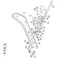
- Fig. 2 is an exploded perspective view of the seat apparatus
- Fig. 3 is a front view of a motor drive unit of the seat tilt apparatus
- Fig. 4 is a perspective view of the motor drive unit of the seat tilt apparatus
- Fig. 5 is a cross-sectional view of the speed reduction device
- Fig. 6 is an exploded perspective view of the speed reduction device
- Fig. 7 is an exploded perspective view of a speed reduction device according to a second embodiment disclosed here.
- Fig. 8 is an exploded perspective view of a speed reduction device according to a third embodiment disclosed here.
- a speed reduction device according to a first embodiment applied to a seat tilt apparatus for a vehicle seat apparatus will be explained.
- directions and orientations such as front and rear (i.e., a longitudinal direction), left and right (i.e., a width direction), and top and bottom correspond to those when viewed from a passenger seated on a seat (i.e., a power seat) for a vehicle.
- the seat tilt apparatus provided at a right side of the seat will be mainly explained as an example.
- a seat apparatus 2 for a vehicle includes a lower rail 4, an upper rail 6, a lower arm 8 at which a seat cushion is mounted, and a seat tilt apparatus 10.
- the seat tilt apparatus 10 includes a motor drive unit 28, which includes a speed reduction device 3.
- the lower rail 4 that extends in a longitudinal direction of the vehicle is fixed to a floor 12 for a vehicle via brackets 14.
- the upper rail 6 is slidably assembled on the lower rail 4.
- a relative sliding of the upper rail 6 to the lower rail 4 is changeable between a locked state and an unlocked state by a lock and unlock mechanism.
- the lower arm 8 is assembled on an upper portion of the upper rail 6 by bracket members 16, 18, bolts and nuts 20, and the like.
- An upper arm of a seat back is assembled on an upper rear portion of the lower arm 8 via a reclining mechanism so as to be rotatable relative to the lower arm 8.
- the seat tilt apparatus 10 is mounted at a front portion of the lower arm 8. As illustrated in Figs. 1 and 2 , the seat tilt apparatus 10 includes a side frame plate 22, a sector gear 24, a pinion gear 26 (see Figs. 3 and 4 ) meshed with an external gear 24a formed at a first end of the sector gear 24, the motor drive unit 28 driving the pinion gear 26, and a swing link member 30 connected to a second end of the sector gear 24.
- the side frame plate 22 includes a top plate portion 22a and a side plate portion 22b bending to form an angle therebetween.
- the side frame plate 22 is pivotally supported by the lower arm 8 at a rotation center bore 23 formed at a rear end of the side plate portion 22b.
- the side plate portion 22b includes a through-hole 34 into which the pinion gear 26 is inserted, en elongated hole 36 into which one of a pair of support projections 120 (which will be explained later) provided to attach the motor drive unit 28 to the lower arm 8 is inserted, and a pivot bore 40 with which one end portion (i.e., a support hole 61) of the swing link member 30 engages.
- a front edge panel 42 serving as a movable portion of the power seat is fixed to the top plate portion 22a of the side frame plate 22 by rivets 44.
- the front edge panel 42 may be directly formed at the side frame plate 22.
- the front edge panel 42 constitutes a portion of a cushion frame to which a lower surface of the seat cushion is fixed.
- a rotation center hole 46 is formed at a center of the sector gear 24 as illustrated in Fig. 2 .
- the external gear 24a having an arc shape and meshed with the pinion gear 26 is formed at the first end of the sector gear 24.
- an operation hole 60 is formed at the second end of the sector gear 24 so as to be connected to the swing link member 30.
- a guide groove 55 is formed at the sector gear 24 so as to extend along the external gear 24a having the arc shape.
- One of the support projections 120 is inserted into the guide groove 55 to thereby guide the swing operation of the sector gear 24.
- a fixed screw 48 which includes a flange portion 48a, a peripheral smooth portion 48b and a serration portion 48c in the above mentioned order from a base portion, is inserted into the rotation center hole 46 in such a manner that the serration portion 48c is assembled on the rotation center hole 46 without relatively rotating thereat.
- the serration portion 48c of the fixed screw 48 is further fitted to an end portion of a drive transmission rod 50 in such a manner that the fixed screw 48 is prevented from rotating relative to the drive transmission rod 50.
- the drive transmission rod 50 transmits a drive torque to another seat tilt apparatus that is provided at a left side of the seat and that includes a lifter link member, a swing link member, a side frame plate, and the like.
- the peripheral smooth portion 48b of the fixed screw 48 is pivotally supported by a fitting hole 52 of the lower arm 8.
- the pinion gear 26 of the motor drive unit 28 is meshed with the external gear 24a, having the arc shape, of the sector gear 24.
- the motor drive unit 28 includes an electric motor (motor) 62 and the speed reduction device 3 as illustrated in Figs. 3 and 4 .
- the motor drive unit 28 is mounted at the lower arm 8 via the two support projections 120, which project in the width direction of the vehicle and into which screw members 128 are inserted respectively.
- An assembly edge portion 66 is formed at an outer periphery of the motor 62 while facing the speed reduction device 3.
- four assembly holes 70 into which assembly screws 68 penetrate are formed at the assembly edge portion 66.
- An output shaft is formed in a projecting manner at a portion of the motor 62 facing the speed reduction device 3.
- a serration fitting hole is formed at an end portion of the output shaft of the motor 62 (i.e., the motor output shaft).
- the serration fitting hole of the output shaft is fitted to a serration portion formed at one end of a worm gear 72 provided at the speed reduction device 3 to thereby integrally connect the motor output shaft to the worm gear 72.
- the speed reduction device 3 includes a casing 80 constituted by a casing body 74 and a casing cover 76 that closes a circular-shaped opening portion 78 of the casing body 74, the worm gear 72 accommodated within the casing body 74 and connected to the output shaft of the motor 62, and a helical gear 82 meshed with the worm gear 72.
- the casing body 74 and the casing cover 76 are each formed by ABS (acrylonitrile butadiene styrene) resin, for example.
- the casing body 74 includes a worm gear accommodating portion 84 and a helical gear accommodating portion 86.
- Front and rear bearings are formed at the worm gear accommodating portion 84 so as to rotatably support both axial ends of the worm gear 72.
- An assembly flange portion 90 is arranged adjacent to the worm gear accommodating portion 84 so as to face the motor 62.
- the assembly flange portion 90 includes a first opening portion 88 that opens in an axial direction of the worm gear 72.
- the assembly flange portion 90 also includes two screw clamp holes 92 at positions facing the respective assembly holes 70 (see Fig. 6 ).
- the motor output shaft is inserted into the first opening portion 88 in such a manner that the end portion of the motor output shaft is connected to the worm gear 72.
- the helical gear 82 is accommodated and arranged within the helical gear accommodating portion 86 in such a manner that an axis of the helical gear 82 is perpendicular to an axis of the worm gear 72.
- a shaft portion 82a having a short-length column shape is formed at one side of the helical gear 82 in a projecting manner and is rotatably supported by a body side bearing portion 94 of the helical gear accommodating portion 86.
- a second opening portion 96 is formed between the worm gear accommodating portion 84 and the helical gear accommodating portion 86 as illustrated in Fig. 6 and at which the worm gear 72 and the helical gear 82 are meshed with each other.
- the helical gear 82 includes three engagement grooves 100 at equal distances around an axial center hole 98 of the helical gear 82.
- An output pinion gear 102 serving as a drive shaft is fitted, via a first end, to the axial center hole 98 and the engagement grooves 100 so that the output pinion gear 102 is prevented from rotating with the helical gear 82.
- a flange portion 102a is formed substantially at a center of the output pinion gear 102 along the circumferential direction so as to receive a thrust load of the helical gear 82.
- an insertion shaft 102b is formed at the first end of the output pinion gear 102 and three engagement fitting portions 102c are formed at equal intervals along the flange portion 102a.
- the insertion shaft 102b is inserted into the axial center hole 98 of the helical gear 82 while the engagement fitting portions 102c engage with the respective engagement grooves 100 of the helical gear 82. Accordingly, the helical gear 82 and the output pinion gear 102 integrally rotate.
- the pinion gear 26 is formed at a shaft portion at a second end of the output pinion gear 102 and is meshed with the external gear 24a of the sector gear 24.
- a peripheral smooth shaft portion 104 is formed, being in contact with the flange portion 102a at an intermediate portion of the output pinion gear 102.
- the output pinion gear 102 is rotatably supported by a cover side bearing portion 106 of the casing cover 76 at the peripheral smooth shaft portion 104.
- a pair of padding portions 110 serving as first assembly portions are formed at an outer circumferential side of the opening portion 78 of the casing body 74.
- Cylindrical projections 112 serving as first engagement portions are integrally formed at respective contact surfaces A of the padding portions 110 relative to the casing cover 76.
- Screw clamp holes 108 serving as cylindrical holes are formed at the respective cylindrical projections 112 so as to penetrate therethrough.
- Internal thread members 109 made of metal are provided at the respective screw clamp holes 108 by insert molding. Then, the screw members 128 (see Fig. 2 ) are meshed with the respective internal thread members 109.
- a first fitting edge 114 projecting towards the casing cover 76 is formed at an inner edge of the circular-shaped opening portion 78.
- a pair of engagement hooks 116 is formed at an upper outer circumferential side of the casing body 74 while an engagement portion 118 (see Figs. 3 and 4 ) is formed at an outer periphery of the worm gear accommodating portion 84 positioned at a lower outer circumferential side of the casing body 74.
- the support projections 120 serving as second assembly portions are formed at portions of the casing cover 76 facing the respective padding portions 110 so as to project in a direction opposite from the padding portions 110.
- a pair of projection insertion bores (i.e., circular holes) 122 which serves as second engagement portions and into which the respective cylindrical projections 112 are inserted are formed at the support projections 120 so as to face the padding portions 110. That is, the projection insertion bores 122 are formed, opening at respective contact surfaces B relative to the casing body 74 .
- through-holes 124 are formed behind the respective projection insertion bores 122, i.e., in a direction away from the padding portions 110, while each having a larger diameter than that of the screw clamp hole 108.
- each of the through-holes 124 and each of the screw clamp holes 108 are connected to each other.
- Guide holes 126 each having a larger diameter than that of the through-hole 124 are formed at the respective support projections 120 while facing the lower arm 8.
- the guide holes 126 are connected to the respective through-holes 124.
- the screw members 128 are inserted into the respective support projections 120 from a side where the lower arm 8 is mounted and are meshed with the internal thread members 109 of the screw clamp holes 108 of the respective cylindrical projections 112 to thereby mount the speed reduction device 3 to the lower arm 8.
- the through-holes 124 and the guide holes 126 of the respective support projections 120 are all larger in diameter than the screw clamp hole 108.
- the screw members 128 are loosely in contact with the through-holes 124 and the guide holes 126. Therefore, when the screw members 128 are tightened, the casing cover 76 is tightened while being sandwiched between the casing body 74 and the lower arm 8.
- the screw members 128 and the internal thread members 109 constitute a tightening means.
- a second fitting edge 130 is formed at the casing cover 76 so as to follow an outer periphery of the first fitting edge 114.
- the first fitting edge 114 and the second fitting edge 130 constitute annular fitting portions.
- a pair of engagement arms 132 is formed at an upper outer circumferential side of the casing cover 76 so as to project towards the casing body 74 and to be engageable with the pair of engagement hooks 116 of the casing body 74.
- a strip-shaped engagement portion 134 is formed at a lower outer circumferential side of the casing cover 76 so as to project towards the casing body 74 and to be engageable with the engagement portion 118 of the casing body 74.
- the swing link member 30 includes a connection hole 58 at the other end and the support hole 61 at one end.
- a connection screw 56 is inserted into the connection hole 58 in addition to the operation hole 60 formed at the second end of the sector gear 24 so that the sector gear 24 and the swing link member 30 are connected in a relatively rotatable manner.
- the support hole 61 formed at one end of the swing link member 30 is connected to the pivot bore 40 of the side frame plate 22 by a support screw 63 so that the swing link member 30 is rotatable relative to the side frame plate 22.
- the worm gear 72 is inserted into the first opening portion 88 of the casing body 74 so that the worm gear 72 is assembled on the worm gear accommodating portion 84.
- the both axial ends of the worm gear 72 are rotatably supported by the respective front and rear bearing portions.
- the helical gear 82 is inserted into the opening portion 78 of the casing body 74 so that the helical gear 82 is assembled on the helical gear accommodating portion 86.
- the helical gear 82 and the worm gear 72 are arranged in such a manner that the axis of the helical gear 82 is perpendicular to the axis of the helical gear 82 and an external gear of the helical gear 82 is meshed with an external gear of the worm gear 72. Then, as illustrated in Fig. 5 , the shaft portion 82a of the helical gear 82 is rotatably supported by the body side bearing portion 94 and thereby accommodating the helical gear 82 within the helical gear accommodating portion 86 (see Fig. 6 ).
- the insertion shaft 102b of the output pinion gear 102 is inserted into the axial center hole 98 of the helical gear 82 so that the engagement fitting portions 102c engage with the respective engagement grooves 100 formed around the axial center hole 98.
- the output pinion gear 102 engages with the helical gear 82 so as not to be rotatable relative thereto.
- the opening portion 78 of the casing body 74 where the helical gear 82 and the output pinion gear 102 are accommodated is closed by the casing cover 76.
- an attachment position between the casing body 74 and the casing cover 76 in a direction perpendicular to an attachment direction therebetween is accurately determined and guided by a mating between the first fitting edge 114 of the casing body 74 and the second fitting edge 130 of the casing cover 76.
- the projection insertion bores 122 formed at the support projections 120 of the casing cover 76 are positioned to face the cylindrical projections 112 formed at the respective padding portions 110 of the casing body 74 so as to determine the attachment position between the casing body 74 and the casing cover 76 in a direction where the first fitting edge 114 and the second fitting edge 130 rotate relative to each other along the circular-shaped opening portion 78. Afterwards, the casing body 74 and the casing cover 76 are attached to each other.
- the engagement hooks 116 of the casing body 74 engage with the respective engagement arms 132 of the casing cover 76 while the strip-shaped engagement portion 134 of the casing cover 76 engages with the engagement portion 118 of the casing body 74, which leads to the temporary joint state where the attachment between the casing body 74 and the casing cover 76 is maintained.
- the casing body 74 and the casing cover 76 are obtained as a single casing 80.
- the peripheral smooth shaft portion 104 of the output pinion gear 102 is rotatably supported by the cover side bearing portion 106 of the casing cover 76.
- the pinion gear 26 of the output pinion gear 102 that projects from an opening of the cover side bearing portion 106 is meshed with the external gear 24a of the sector gear 24 when the speed reduction device 3 is mounted at the lower arm 8.
- the motor 62 is assembled on the speed reduction device 3.
- the motor output shaft is inserted into the first opening portion 88 of the casing body 74.
- the serration portion of the worm gear 72 is then fitted to the serration fitting hole formed at the end portion of the motor output shaft so that the motor output shaft and the worm gear 72 are connected to each other in an integrally rotating manner.
- the assembly holes 70 formed at the assembly edge portions 66 that are provided at the outer circumference of the motor 62 are coaxially arranged to face the pair of screw clamp holes 92 of the casing body 74.
- the speed reduction device 3 and the motor 62 are integrally assembled on each other by the assembly screws 68 inserted into the assembly holes 70 and the screw clamp holes 92.
- the motor drive unit 28 which is constituted by the speed reduction device 3 and the motor 62 integrally assembled on each other, is mounted at the lower arm 8 on which the sector gear 24, the swing link member 30 and the side frame plate 22 are assembled beforehand.
- the screw members 128 are inserted, from a side where the lower arm 8 is arranged, to the guide holes 126 and the through-holes 124 of the respective support projections 120, and the screw clamp holes 108 of the respective cylindrical projections 112.
- the screw members 128 are meshed with the internal thread members 109 of the screw clamp holes 108 to thereby mount the motor drive unit 28 at the lower arm 8.
- one of the support projections 120 is inserted into the elongated hole 36 of the side frame plate 22 and the output pinion 102 is inserted into the through-hole 34 of the side frame plate 22. Then, the pinion gear 26 of the output pinion gear 102 is meshed with the external gear 24a of the sector gear 24.
- the motor 62 is driven so that a driving force thereof is transmitted via the speed reduction device 3 to the output pinion gear 102 which rotates accordingly (see Fig. 3 ).
- the output pinion gear 102 rotates
- the external gear 24a of the sector gear 24 meshed with the pinion gear 26 moves downward to thereby rotate the operation hole 60 of the sector gear 24 upward (i.e., the sector gear 24 rotates in the clockwise direction in Fig. 2 ).
- the swing link member 30, which is rotatably connected to the operation hole 60 at the connection hole 58, moves upward in association with the rotation of the sector gear 24.
- the support hole 61 of the swing link member 30 is connected to the pivot bore 40 of the side frame plate 22.
- the side frame plate 22 rotates upward about the rotation center bore 23.
- the front edge panel 42 fixed to the side frame plate 22 and a front portion of the seat cushion move upward. The operation of the seat tilt apparatus 10 is thus achieved.
- the casing body 74 and the casing cover 76 are attached to each other via the first fitting edge 114 and the second fitting edge 130 formed at the respective contact surfaces A and B.
- the positioning of the casing body 74 and the casing cover 76 in the direction perpendicular to the attachment direction therebetween is easily conducted.
- the positioning in the direction where the casing body 74 and the casing cover 76 rotate relative to each other along the opening portion 78 is not achieved only by the first and second fitting edges 114 and 130.
- the cylindrical projections 112 formed at the outer circumferential side of the first fitting edge 114 and the projection insertion bores 122 formed at the outer circumferential side of the second fitting edge 130 are fitted to each other, thereby achieving the positioning of the casing body 74 and the casing cover 76 in the direction where the casing body 74 and the casing cover 76 rotate relative to each other along the opening portion 78.
- the position where the casing body 74 and the casing cover 76 are attached to each other is appropriately determined to thereby quickly and accurately assemble the casing body 74 and the casing cover 76 on each other.
- the casing body 74 and the casing cover 76 are securely and strongly assembled on each other in a state where the first and second fitting edges 114 and 130 are fitted to each other and the cylindrical projections 112 are inserted into the projection insertion bores 122.
- a relative positional displacement between the casing body 74 and the casing cover 76 in the direction perpendicular to the attachment direction and the direction where the casing body 74 and the casing cover 76 rotate relative to each other may be restrained.
- cylindrical projections 112 are formed at the padding portions 110 where the casing cover 76 is in contact with the casing body 74.
- the projection insertion bores 122 are formed at the respective support projections 120. Then, the padding portions 110 and the support projections 120 are tightened with each other by the screw members 128, thereby strongly and securely maintaining the fitting between the cylindrical projections 112 and the projection insertion bores 122.
- the relative positional displacement between the casing body 74 and the casing cover 76 is further strongly restrained. Therefore, in combination with the fitting between the first fitting edge 114 and the second fitting edge 130, axes of the body side bearing portion 94 and the cover side bearing portion 106 supporting the helical gear 82 are prevented from being displaced. The stable mesh between the helical gear 82 and the worm gear 72 are ensured while a high bearing rigidity thereof is secured.
- each of the cylindrical projections 112 and the projection insertion bore (cylindrical hole) 122 are tightened at respective axial centers thereof by the screw member 128.
- the padding portions 110 and the support projections 120 contribute to space saving, thereby achieving a downsizing of the casing 80.
- the casing body 74 and the casing cover 76 are both formed by lightweight resin, which leads to a reduced cost for an accurate fitting shape. The reduction in weight and cost for the entire speed reduction device 3 may be achieved accordingly.
- the attachment between the casing body 74 and the casing cover 76 and the assembly of the whole casing 80 on the seat frame are simultaneously performed by the tightening of the padding portions 110 and the support projections 120 by the screw members 128.
- exclusive structures and components are not required individually for the attachment between the casing body 74 and the casing cover 76 and the assembly of the whole casing 80 on the seat frame.
- the attachment operation and the assembly operation are simultaneously performed to thereby improve operation efficiency.
- the casing body 74 and the casing cover 76 are attached with a highly strong structure for assembling the whole casing 80 on the seat frame.
- the casing body 74 and the casing cover 76 are further strongly assembled.
- a speed reduction device 200 of the second embodiment includes a casing 201 constituted by a casing body 202 and a casing cover 206 in the same way as the first embodiment.
- a pair of round bar-shaped engagement projections 204 serving as the first engagement portions and projecting towards the casing cover 206 are formed at the outer circumferential side of each of the screw clamp holes 108 formed at the padding portion 110 of the casing body 202.
- a pair of projection engagement bores 208 serving as the second engagement portions and being engageable with the respective engagement projections 204 are formed at the outer circumferential side of each of the through-holes 124 of the support projection 120 of the casing cover 206.
- the casing body 202 and the casing cover 206 are attached to each other by the pair of engagement projections 204 formed at each of the padding portions 110 of the casing body 202 being fitted to the pair of projection engagement bores 208 formed at each of the support projections 120 of the casing cover 206.
- the attachment position in the direction where the first fitting edge 114 and the second fitting edge 130 rotate relative to each other along the circular-shaped opening portion 78 is determined by the round bar-shaped engagement projections 204, for which molding is easily conducted, and by the projection engagement bores 208. As a result, a further reduction of the manufacturing cost may be achieved.
- a speed reduction device 250 includes a casing 251 constituted by a casing body 252 and a casing cover 256 in the same way as the first embodiment.
- a prismatic projection 254 serving as the first engaging portion is formed, projecting towards the casing cover 256, at each of the padding portions 110 of the casing body 252.
- the prismatic projection 254 is arranged at the outer circumferential side of each of the screw clamp holes 108 that opens at an end portion of the padding portion 110.
- a square engagement bore 258 serving as the second engagement portion and being engageable with the prismatic projection 254 is formed at the outer circumferential side of each of the through-holes 124 that opens towards the casing body 252.
- the casing body 252 and the casing cover 256 are attached to each other by the prismatic projection 254 formed at each of the padding portions 110 of the casing body 252 being fitted to the square engagement bore 258 formed at each of the support projections 120 of the casing cover 256. Accordingly, the attachment position in the direction where the first fitting edge 114 and the second fitting edge 130 rotate relative to each other along the circular-shaped opening portion 78 is determined by the prismatic projection 254, for which molding is easily conducted, and the square engagement bores 258. As a result, a further reduction of the manufacturing cost may be achieved.
- the screw members 128 are tightened to the internal thread members 109 formed at the respective screw clamp holes 108 to thereby attach the casing body 74 and the casing cover 76 to each other.
- an internal thread portion meshed with each of the screw members 128 may be formed at an inner peripheral wall of each of the screw clamp holes.
- through-holes into which bolts (screw members) are inserted may be formed at both padding portions 110 of the casing body 74 and the support projections 120 of the casing cover 76. Then, the bolts are inserted into the through-holes and nuts may be tightened from a side facing the casing body.
- the casing body 74 and the casing cover 76 are formed by ABS resin.
- the casing body 74 and the casing cover 76 may be formed by resin reinforced by glass fiber, aramid fiber, or the like.
- the cylindrical projections 112 are formed at the padding portions 110 (the first assembly portions) of the casing body 74 while the projection insertion bores 122 (the second engagement portions) are formed at the support projections 120 (the second assembly portions) of the casing cover 76.
- circular holes may be formed at the first assembly portions while projecting engagement portions (the first engagement portions) fitted to the circular holes may be formed at the second assembly portions.
Landscapes
- Engineering & Computer Science (AREA)
- General Engineering & Computer Science (AREA)
- Mechanical Engineering (AREA)
- Aviation & Aerospace Engineering (AREA)
- Transportation (AREA)
- Seats For Vehicles (AREA)
- Chairs For Special Purposes, Such As Reclining Chairs (AREA)
- Gear Transmission (AREA)
Abstract
Description
- This disclosure relates to a speed reduction device for a power seat.
- A known power seat apparatus for a vehicle includes a speed reduction device that reduces a rotational speed of an output shaft of a drive source such as an electric motor and then transmits the resulting rotational speed (i.e., the rotation) to a drive shaft driving a movable portion of the power seat.
US6390264B2 (hereinafter referred to as Reference 1) discloses such speed reduction device including a casing constituted by two members, i.e., a holding member (a casing body) and a cover member (casing cover). The holding member holds a worm gear and a helical gear that perform a speed reduction operation in a rotatable manner. The cover member covers the holding member. Then, four engagement projections are formed at an outer circumference of the cover member while engagement portions are formed at the holding member so as to face the respective engagement portions. A worm gear that rotates in the same direction and at the same speed as those of the output shaft of the motor (i.e., the motor output shaft) is assembled on an end portion of the holding member. A helical gear having an axial center perpendicular to an axial center of the worm gear and meshed with the worm gear is assembled on the holding member. The cover member is attached to the holding member in such a manner that the engagement projections of the cover member engage with the respective engagement portions of the holding member, the engagement portions then being riveted to thereby fix the cover member to the holding member. Accordingly, the casing of the speed reduction device is constituted by the two members in order to simplify an assembly of the worm gear and the helical gear. Besides the riveting, a fixing method of the two members may be generally achieved by a tightening with multiple small screws. In addition, in a case of mounting the speed reduction device itself to a seat frame, for example, fitting screws penetrate through three engagement holes formed at an outer peripheral portion of the holding member so that the holding member is meshed with the seat frame as disclosed in Reference 1. - However, according to the speed reduction device disclosed in Reference 1, the attachment of the cover member to the holding member and the assembly of the speed reduction device itself on the seat frame are separately and independently performed from each other. Thus, exclusive components and processes are necessary for attaching the cover member to the holding member and for assembling the speed reduction device itself on the seat frame, thereby increasing the number of components and processing. In addition, because the helical gear receives a large radial load and a thrust load from the worm gear, the casing is required to have a high bearing rigidity for holding both the worm gear and the helical gear so that a stable mesh between the gears is ensured. As a result, the holding member and the cover member after being attached to constitute the casing are both required to have a high holding force. Further, a general requirement for quickly and precisely assemble the holding member and the cover member on each other is still present.
- A need thus exists for a speed reduction device for a power seat in which an assembly of a casing is quickly and precisely performed and the number of components and processes for the assembly is reduced to achieve a manufacturing cost reduction while a bearing rigidity of gears accommodated within the casing is enhanced to secure a stable mesh between the gears.
- According to an aspect of this disclosure, a speed reduction device for a power seat adapted to be fixed to a seat frame, the speed reduction device includes a worm gear coaxially and integrally rotating with an output shaft of a motor, a helical gear meshed with the worm gear and coaxially and integrally rotating with a drive shaft driving a movable portion of the power seat, and a casing accommodating the worm gear and the helical gear to be rotatable. The casing includes a casing body rotatably supporting the worm gear and including a circular-shaped opening portion through which the helical gear is inserted, a casing cover tightened to the casing body and closing the opening portion of the casing body, annular fitting portions formed at contact surfaces of the casing body and the casing cover respectively and fitted to each other, a first engagement portion formed at an outer circumferential side of the annular fitting portion of one of the casing body and the casing cover, a second engagement portion formed at the other of the casing body and the casing cover and engaging with the first engagement portion, and a tightening means tightening the casing cover to the casing body.
- According to the aforementioned disclosure, the casing body and the casing cover are attached to each other via the annular fitting portions formed at the respective contact surfaces of the casing body and the casing cover. Thus, the positioning of the casing body and the casing cover in the direction perpendicular to the attachment direction therebetween is easily conducted. In this case, the positioning in the direction where the casing body and the casing cover rotate relative to each other along the opening portion is not achieved only by the annular fitting portions. However, the first engagement portion formed at the outer circumferential side of the annular fitting portion and the second engagement portion fitted to the first engagement portion are fitted to each other, thereby achieving the positioning of the casing body and the casing cover in the direction where the casing body and the casing cover rotate relative to each other along the opening portion. As a result, the position where the casing body and the casing cover are attached to each other is appropriately determined to thereby quickly and accurately assemble the casing body and the casing cover on each other. Further, the casing body and the casing cover are assembled on and tightened to each other in a state where the annular fitting portions are fitted to each other and the first and second engagement portions engage with each other. As a result, a relative positional displacement between the casing body and the casing cover in the direction perpendicular to the attachment direction and the direction where the casing body and the casing cover rotate relative to each other may be restrained. The stable mesh between the helical gear and the worm gear accommodated within the casing is ensured while a high bearing rigidity is secured.
- The casing body and the casing cover are both formed by a resin material.
- As a result, the casing body and the casing cover are both formed by lightweight resin, which leads to a reduced cost for an accurate fitting shape. The reduction in weight and cost for the entire speed reduction device may be achieved accordingly.
- The casing body includes a plurality of first assembly portions while the casing cover includes a plurality of second assembly portions assembled on the respective first assembly portions, one of the first assembly portions and the second assembly portions each being provided with the first engagement portion which projects from one of the contact surfaces, the other of the first assembly portions and the second assembly portions each being provided with the second engagement portion which has a hole shaped opening at the other of the contact surfaces and with which the first engagement portion engages, and the casing body and the casing cover are tightened by the tightening means via the first assembly portions and the second assembly portions.
- A simple structure where the first engagement portions each having the projecting shape and the second engagement portions each having a hole shape engage each other achieves the easy and accurate determination of the relative position in the direction where the casing body and the casing cover rotate relative to each other along the opening portion. Further, because the first engagement portions are formed at one of the first assembly portions and the second assembly portions while the second engagement portions are formed at the other of the first assembly portions and the second assembly portions, and the first and second assembly portions are tightened to each other by the tightening means, the engagement between the first engagement portions and the second engagement portions is securely maintained, thereby further strongly preventing the relative positional displacement between the casing body and the casing cover.
- The first engagement portion is a cylindrical projection integrally formed at one of the contact surfaces and the second engagement portion is a circular hole opening at the other of the contact surfaces, the tightening means being arranged at an axial center of a cylindrical hole formed at the cylindrical projection and an axial center of the circular hole.
- A simple structure where the cylindrical projection is fitted to the circular hole achieves the easy and accurate determination of the relative position in the direction where the casing body and the casing cover rotate relative to each other along the opening portion. Further, the tightening means is arranged at respective axial centers of the cylindrical hole of the cylindrical projection and the circular hole. Thus, the first assembly portions and the second assembly portions contribute to space saving, thereby achieving a downsizing of the casing.
- The casing body and the casing cover are mounted at the seat frame by the tightening means via the first assembly portions and the second assembly portions in a state where the casing body and the casing cover contact each other at the respective contact surfaces.
- The attachment between the casing body and the casing cover and the assembly of the whole casing on the seat frame are simultaneously performed by the tightening of the first assembly portions and the second assembly portions by the tightening means. Thus, exclusive structures and components are not required individually for the attachment between the casing body and the casing cover and the assembly between the whole casing and the seat frame. As a result, a reduction in manufacturing cost may be obtained. The attachment operation and the assembly operation are simultaneously performed to thereby improve operation efficiency. The casing body and the casing cover are attached with a highly strong structure for assembling the whole casing on the seat frame. Thus, the casing body and the casing cover are further strongly assembled.
- The foregoing and additional features and characteristics of this disclosure will become more apparent from the following detailed description considered with the reference to the accompanying drawings, wherein:
-
Fig. 1 is a perspective view of a seat apparatus for a vehicle equipped with a seat tilt apparatus including a speed reduction device according to a first embodiment disclosed here; -
Fig. 2 is an exploded perspective view of the seat apparatus; -
Fig. 3 is a front view of a motor drive unit of the seat tilt apparatus; -
Fig. 4 is a perspective view of the motor drive unit of the seat tilt apparatus; -
Fig. 5 is a cross-sectional view of the speed reduction device; -
Fig. 6 is an exploded perspective view of the speed reduction device; -
Fig. 7 is an exploded perspective view of a speed reduction device according to a second embodiment disclosed here; and -
Fig. 8 is an exploded perspective view of a speed reduction device according to a third embodiment disclosed here. - A speed reduction device according to a first embodiment applied to a seat tilt apparatus for a vehicle seat apparatus will be explained. In the following, directions and orientations such as front and rear (i.e., a longitudinal direction), left and right (i.e., a width direction), and top and bottom correspond to those when viewed from a passenger seated on a seat (i.e., a power seat) for a vehicle. Further, in the following, the seat tilt apparatus provided at a right side of the seat will be mainly explained as an example.
- As illustrated in
Fig. 1 , aseat apparatus 2 for a vehicle includes a lower rail 4, an upper rail 6, alower arm 8 at which a seat cushion is mounted, and aseat tilt apparatus 10. Theseat tilt apparatus 10 includes amotor drive unit 28, which includes aspeed reduction device 3. According to theseat apparatus 2, the lower rail 4 that extends in a longitudinal direction of the vehicle is fixed to afloor 12 for a vehicle viabrackets 14. The upper rail 6 is slidably assembled on the lower rail 4. A relative sliding of the upper rail 6 to the lower rail 4 is changeable between a locked state and an unlocked state by a lock and unlock mechanism. Thelower arm 8 is assembled on an upper portion of the upper rail 6 bybracket members nuts 20, and the like. An upper arm of a seat back is assembled on an upper rear portion of thelower arm 8 via a reclining mechanism so as to be rotatable relative to thelower arm 8. - The
seat tilt apparatus 10 is mounted at a front portion of thelower arm 8. As illustrated inFigs. 1 and2 , theseat tilt apparatus 10 includes aside frame plate 22, asector gear 24, a pinion gear 26 (seeFigs. 3 and 4 ) meshed with anexternal gear 24a formed at a first end of thesector gear 24, themotor drive unit 28 driving thepinion gear 26, and aswing link member 30 connected to a second end of thesector gear 24. Theside frame plate 22 includes atop plate portion 22a and aside plate portion 22b bending to form an angle therebetween. Theside frame plate 22 is pivotally supported by thelower arm 8 at a rotation center bore 23 formed at a rear end of theside plate portion 22b. That is, afitting screw 25 is inserted into the rotation center bore 23 of theside frame plate 22 and afitting bore 32 formed at an inner side surface of thelower arm 8. As illustrated inFig. 2 , theside plate portion 22b includes a through-hole 34 into which thepinion gear 26 is inserted, enelongated hole 36 into which one of a pair of support projections 120 (which will be explained later) provided to attach themotor drive unit 28 to thelower arm 8 is inserted, and a pivot bore 40 with which one end portion (i.e., a support hole 61) of theswing link member 30 engages. - As illustrated in
Fig. 1 , afront edge panel 42 serving as a movable portion of the power seat is fixed to thetop plate portion 22a of theside frame plate 22 byrivets 44. Alternatively, thefront edge panel 42 may be directly formed at theside frame plate 22. Thefront edge panel 42 constitutes a portion of a cushion frame to which a lower surface of the seat cushion is fixed. - A
rotation center hole 46 is formed at a center of thesector gear 24 as illustrated inFig. 2 . Theexternal gear 24a having an arc shape and meshed with thepinion gear 26 is formed at the first end of thesector gear 24. In addition, anoperation hole 60 is formed at the second end of thesector gear 24 so as to be connected to theswing link member 30. Further, aguide groove 55 is formed at thesector gear 24 so as to extend along theexternal gear 24a having the arc shape. One of thesupport projections 120 is inserted into theguide groove 55 to thereby guide the swing operation of thesector gear 24. A fixedscrew 48, which includes aflange portion 48a, a peripheralsmooth portion 48b and aserration portion 48c in the above mentioned order from a base portion, is inserted into therotation center hole 46 in such a manner that theserration portion 48c is assembled on therotation center hole 46 without relatively rotating thereat. Theserration portion 48c of the fixedscrew 48 is further fitted to an end portion of adrive transmission rod 50 in such a manner that the fixedscrew 48 is prevented from rotating relative to thedrive transmission rod 50. Thedrive transmission rod 50 transmits a drive torque to another seat tilt apparatus that is provided at a left side of the seat and that includes a lifter link member, a swing link member, a side frame plate, and the like. The peripheralsmooth portion 48b of the fixedscrew 48 is pivotally supported by afitting hole 52 of thelower arm 8. Thepinion gear 26 of themotor drive unit 28 is meshed with theexternal gear 24a, having the arc shape, of thesector gear 24. - The
motor drive unit 28 includes an electric motor (motor) 62 and thespeed reduction device 3 as illustrated inFigs. 3 and 4 . Themotor drive unit 28 is mounted at thelower arm 8 via the twosupport projections 120, which project in the width direction of the vehicle and into which screwmembers 128 are inserted respectively. Anassembly edge portion 66 is formed at an outer periphery of themotor 62 while facing thespeed reduction device 3. In addition, four assembly holes 70 (seeFig. 6 ) into which assembly screws 68 penetrate are formed at theassembly edge portion 66. An output shaft is formed in a projecting manner at a portion of themotor 62 facing thespeed reduction device 3. Then, a serration fitting hole is formed at an end portion of the output shaft of the motor 62 (i.e., the motor output shaft). The serration fitting hole of the output shaft is fitted to a serration portion formed at one end of aworm gear 72 provided at thespeed reduction device 3 to thereby integrally connect the motor output shaft to theworm gear 72. - The
speed reduction device 3 includes acasing 80 constituted by acasing body 74 and acasing cover 76 that closes a circular-shapedopening portion 78 of thecasing body 74, theworm gear 72 accommodated within thecasing body 74 and connected to the output shaft of themotor 62, and ahelical gear 82 meshed with theworm gear 72. Thecasing body 74 and thecasing cover 76 are each formed by ABS (acrylonitrile butadiene styrene) resin, for example. Thecasing body 74 includes a wormgear accommodating portion 84 and a helicalgear accommodating portion 86. Front and rear bearings are formed at the wormgear accommodating portion 84 so as to rotatably support both axial ends of theworm gear 72. Anassembly flange portion 90 is arranged adjacent to the wormgear accommodating portion 84 so as to face themotor 62. Theassembly flange portion 90 includes afirst opening portion 88 that opens in an axial direction of theworm gear 72. Theassembly flange portion 90 also includes two screw clamp holes 92 at positions facing the respective assembly holes 70 (seeFig. 6 ). The motor output shaft is inserted into thefirst opening portion 88 in such a manner that the end portion of the motor output shaft is connected to theworm gear 72. Thehelical gear 82 is accommodated and arranged within the helicalgear accommodating portion 86 in such a manner that an axis of thehelical gear 82 is perpendicular to an axis of theworm gear 72. As illustrated inFig. 5 , ashaft portion 82a having a short-length column shape is formed at one side of thehelical gear 82 in a projecting manner and is rotatably supported by a bodyside bearing portion 94 of the helicalgear accommodating portion 86. Asecond opening portion 96 is formed between the wormgear accommodating portion 84 and the helicalgear accommodating portion 86 as illustrated inFig. 6 and at which theworm gear 72 and thehelical gear 82 are meshed with each other. Thehelical gear 82 includes threeengagement grooves 100 at equal distances around anaxial center hole 98 of thehelical gear 82. Anoutput pinion gear 102 serving as a drive shaft is fitted, via a first end, to theaxial center hole 98 and theengagement grooves 100 so that theoutput pinion gear 102 is prevented from rotating with thehelical gear 82. As illustrated inFigs. 5 and6 , aflange portion 102a is formed substantially at a center of theoutput pinion gear 102 along the circumferential direction so as to receive a thrust load of thehelical gear 82. In addition, aninsertion shaft 102b is formed at the first end of theoutput pinion gear 102 and threeengagement fitting portions 102c are formed at equal intervals along theflange portion 102a. Theinsertion shaft 102b is inserted into theaxial center hole 98 of thehelical gear 82 while theengagement fitting portions 102c engage with therespective engagement grooves 100 of thehelical gear 82. Accordingly, thehelical gear 82 and theoutput pinion gear 102 integrally rotate. Thepinion gear 26 is formed at a shaft portion at a second end of theoutput pinion gear 102 and is meshed with theexternal gear 24a of thesector gear 24. A peripheralsmooth shaft portion 104 is formed, being in contact with theflange portion 102a at an intermediate portion of theoutput pinion gear 102. Theoutput pinion gear 102 is rotatably supported by a coverside bearing portion 106 of thecasing cover 76 at the peripheralsmooth shaft portion 104. - As illustrated in
Figs. 5 and6 , a pair ofpadding portions 110 serving as first assembly portions are formed at an outer circumferential side of the openingportion 78 of thecasing body 74.Cylindrical projections 112 serving as first engagement portions are integrally formed at respective contact surfaces A of thepadding portions 110 relative to thecasing cover 76. Screw clamp holes 108 serving as cylindrical holes are formed at the respectivecylindrical projections 112 so as to penetrate therethrough.Internal thread members 109 made of metal are provided at the respective screw clamp holes 108 by insert molding. Then, the screw members 128 (seeFig. 2 ) are meshed with the respectiveinternal thread members 109. A firstfitting edge 114 projecting towards thecasing cover 76 is formed at an inner edge of the circular-shapedopening portion 78. A pair of engagement hooks 116 is formed at an upper outer circumferential side of thecasing body 74 while an engagement portion 118 (seeFigs. 3 and 4 ) is formed at an outer periphery of the wormgear accommodating portion 84 positioned at a lower outer circumferential side of thecasing body 74. - The
support projections 120 serving as second assembly portions are formed at portions of thecasing cover 76 facing therespective padding portions 110 so as to project in a direction opposite from thepadding portions 110. A pair of projection insertion bores (i.e., circular holes) 122 which serves as second engagement portions and into which the respectivecylindrical projections 112 are inserted are formed at thesupport projections 120 so as to face thepadding portions 110. That is, the projection insertion bores 122 are formed, opening at respective contact surfaces B relative to thecasing body 74 . Next, through-holes 124 are formed behind the respective projection insertion bores 122, i.e., in a direction away from thepadding portions 110, while each having a larger diameter than that of thescrew clamp hole 108. Thus, in a case where thecylindrical projections 112 are inserted into the respective projection insertion bores 122, each of the through-holes 124 and each of the screw clamp holes 108 are connected to each other. Guide holes 126 each having a larger diameter than that of the through-hole 124 are formed at therespective support projections 120 while facing thelower arm 8. The guide holes 126 are connected to the respective through-holes 124. Thescrew members 128 are inserted into therespective support projections 120 from a side where thelower arm 8 is mounted and are meshed with theinternal thread members 109 of the screw clamp holes 108 of the respectivecylindrical projections 112 to thereby mount thespeed reduction device 3 to thelower arm 8. At this time, the through-holes 124 and the guide holes 126 of therespective support projections 120 are all larger in diameter than thescrew clamp hole 108. Thus, thescrew members 128 are loosely in contact with the through-holes 124 and the guide holes 126. Therefore, when thescrew members 128 are tightened, thecasing cover 76 is tightened while being sandwiched between thecasing body 74 and thelower arm 8. Thescrew members 128 and theinternal thread members 109 constitute a tightening means. A secondfitting edge 130 is formed at thecasing cover 76 so as to follow an outer periphery of the firstfitting edge 114. The firstfitting edge 114 and the secondfitting edge 130 constitute annular fitting portions. - A pair of
engagement arms 132 is formed at an upper outer circumferential side of thecasing cover 76 so as to project towards thecasing body 74 and to be engageable with the pair of engagement hooks 116 of thecasing body 74. A strip-shapedengagement portion 134 is formed at a lower outer circumferential side of thecasing cover 76 so as to project towards thecasing body 74 and to be engageable with theengagement portion 118 of thecasing body 74. The engagement hooks 116 and theengagement arms 132, and theengagement portion 118 and the strip-shapedengagement portion 134 achieve a temporary joint state where thecasing body 74 and thecasing cover 76 are assembled on each other before being mounted at thelower arm 8. Because thecasing body 74 and thecasing cover 76 are handled as a unit in the temporary joint state, operation efficiency when thecasing 80 is mounted at thelower arm 8 may be enhanced. - As illustrated in
Fig. 2 , theswing link member 30 includes aconnection hole 58 at the other end and thesupport hole 61 at one end. Aconnection screw 56 is inserted into theconnection hole 58 in addition to theoperation hole 60 formed at the second end of thesector gear 24 so that thesector gear 24 and theswing link member 30 are connected in a relatively rotatable manner. Thesupport hole 61 formed at one end of theswing link member 30 is connected to the pivot bore 40 of theside frame plate 22 by asupport screw 63 so that theswing link member 30 is rotatable relative to theside frame plate 22. - An assembly of the speed reduction device having the aforementioned structure will be explained. As illustrated in
Fig. 6 , theworm gear 72 is inserted into thefirst opening portion 88 of thecasing body 74 so that theworm gear 72 is assembled on the wormgear accommodating portion 84. At this time, the both axial ends of theworm gear 72 are rotatably supported by the respective front and rear bearing portions. Next, thehelical gear 82 is inserted into the openingportion 78 of thecasing body 74 so that thehelical gear 82 is assembled on the helicalgear accommodating portion 86. At this time, thehelical gear 82 and theworm gear 72 are arranged in such a manner that the axis of thehelical gear 82 is perpendicular to the axis of thehelical gear 82 and an external gear of thehelical gear 82 is meshed with an external gear of theworm gear 72. Then, as illustrated inFig. 5 , theshaft portion 82a of thehelical gear 82 is rotatably supported by the bodyside bearing portion 94 and thereby accommodating thehelical gear 82 within the helical gear accommodating portion 86 (seeFig. 6 ). Next, theinsertion shaft 102b of theoutput pinion gear 102 is inserted into theaxial center hole 98 of thehelical gear 82 so that theengagement fitting portions 102c engage with therespective engagement grooves 100 formed around theaxial center hole 98. As a result, theoutput pinion gear 102 engages with thehelical gear 82 so as not to be rotatable relative thereto. - As illustrated in
Fig. 6 , the openingportion 78 of thecasing body 74 where thehelical gear 82 and theoutput pinion gear 102 are accommodated is closed by thecasing cover 76. In doing so, first, an attachment position between thecasing body 74 and thecasing cover 76 in a direction perpendicular to an attachment direction therebetween is accurately determined and guided by a mating between the firstfitting edge 114 of thecasing body 74 and the secondfitting edge 130 of thecasing cover 76. Next, the projection insertion bores 122 formed at thesupport projections 120 of thecasing cover 76 are positioned to face thecylindrical projections 112 formed at therespective padding portions 110 of thecasing body 74 so as to determine the attachment position between thecasing body 74 and thecasing cover 76 in a direction where the firstfitting edge 114 and the secondfitting edge 130 rotate relative to each other along the circular-shapedopening portion 78. Afterwards, thecasing body 74 and thecasing cover 76 are attached to each other. At this time, the engagement hooks 116 of thecasing body 74 engage with therespective engagement arms 132 of thecasing cover 76 while the strip-shapedengagement portion 134 of thecasing cover 76 engages with theengagement portion 118 of thecasing body 74, which leads to the temporary joint state where the attachment between thecasing body 74 and thecasing cover 76 is maintained. According to the temporary joint state, thecasing body 74 and thecasing cover 76 are obtained as asingle casing 80. When thecasing body 74 and thecasing cover 76 are attached to each other, the peripheralsmooth shaft portion 104 of theoutput pinion gear 102 is rotatably supported by the coverside bearing portion 106 of thecasing cover 76. Thepinion gear 26 of theoutput pinion gear 102 that projects from an opening of the coverside bearing portion 106 is meshed with theexternal gear 24a of thesector gear 24 when thespeed reduction device 3 is mounted at thelower arm 8. - Next, the
motor 62 is assembled on thespeed reduction device 3. The motor output shaft is inserted into thefirst opening portion 88 of thecasing body 74. The serration portion of theworm gear 72 is then fitted to the serration fitting hole formed at the end portion of the motor output shaft so that the motor output shaft and theworm gear 72 are connected to each other in an integrally rotating manner. The assembly holes 70 formed at theassembly edge portions 66 that are provided at the outer circumference of themotor 62 are coaxially arranged to face the pair of screw clamp holes 92 of thecasing body 74. Thespeed reduction device 3 and themotor 62 are integrally assembled on each other by the assembly screws 68 inserted into the assembly holes 70 and the screw clamp holes 92. - Then, the
motor drive unit 28, which is constituted by thespeed reduction device 3 and themotor 62 integrally assembled on each other, is mounted at thelower arm 8 on which thesector gear 24, theswing link member 30 and theside frame plate 22 are assembled beforehand. At this time, thescrew members 128 are inserted, from a side where thelower arm 8 is arranged, to the guide holes 126 and the through-holes 124 of therespective support projections 120, and the screw clamp holes 108 of the respectivecylindrical projections 112. Thescrew members 128 are meshed with theinternal thread members 109 of the screw clamp holes 108 to thereby mount themotor drive unit 28 at thelower arm 8. At the time of mounting themotor drive unit 28 at thelower arm 8, one of thesupport projections 120 is inserted into theelongated hole 36 of theside frame plate 22 and theoutput pinion 102 is inserted into the through-hole 34 of theside frame plate 22. Then, thepinion gear 26 of theoutput pinion gear 102 is meshed with theexternal gear 24a of thesector gear 24. - Next, an operation of the
speed reduction device 3 having the aforementioned structure will be explained with reference toFigs. 1 and2 . For example, in a case of raising theseat tilt apparatus 10, themotor 62 is driven so that a driving force thereof is transmitted via thespeed reduction device 3 to theoutput pinion gear 102 which rotates accordingly (seeFig. 3 ). When theoutput pinion gear 102 rotates, theexternal gear 24a of thesector gear 24 meshed with thepinion gear 26 moves downward to thereby rotate theoperation hole 60 of thesector gear 24 upward (i.e., thesector gear 24 rotates in the clockwise direction inFig. 2 ). Theswing link member 30, which is rotatably connected to theoperation hole 60 at theconnection hole 58, moves upward in association with the rotation of thesector gear 24. On the other hand, thesupport hole 61 of theswing link member 30 is connected to the pivot bore 40 of theside frame plate 22. Thus, in association with the upward movement of theswing link member 30, theside frame plate 22 rotates upward about the rotation center bore 23. Then, when theside frame plate 22 rotates upward, thefront edge panel 42 fixed to theside frame plate 22 and a front portion of the seat cushion move upward. The operation of theseat tilt apparatus 10 is thus achieved. - According to the
speed reduction device 3 having the aforementioned structure, thecasing body 74 and thecasing cover 76 are attached to each other via the firstfitting edge 114 and the secondfitting edge 130 formed at the respective contact surfaces A and B. Thus, the positioning of thecasing body 74 and thecasing cover 76 in the direction perpendicular to the attachment direction therebetween is easily conducted. In this case, the positioning in the direction where thecasing body 74 and thecasing cover 76 rotate relative to each other along the openingportion 78 is not achieved only by the first and secondfitting edges cylindrical projections 112 formed at the outer circumferential side of the firstfitting edge 114 and the projection insertion bores 122 formed at the outer circumferential side of the secondfitting edge 130 are fitted to each other, thereby achieving the positioning of thecasing body 74 and thecasing cover 76 in the direction where thecasing body 74 and thecasing cover 76 rotate relative to each other along the openingportion 78. As a result, the position where thecasing body 74 and thecasing cover 76 are attached to each other is appropriately determined to thereby quickly and accurately assemble thecasing body 74 and thecasing cover 76 on each other. Further, thecasing body 74 and thecasing cover 76 are securely and strongly assembled on each other in a state where the first and secondfitting edges cylindrical projections 112 are inserted into the projection insertion bores 122. As a result, a relative positional displacement between thecasing body 74 and thecasing cover 76 in the direction perpendicular to the attachment direction and the direction where thecasing body 74 and thecasing cover 76 rotate relative to each other may be restrained. - In addition, the
cylindrical projections 112 are formed at thepadding portions 110 where thecasing cover 76 is in contact with thecasing body 74. The projection insertion bores 122 are formed at therespective support projections 120. Then, thepadding portions 110 and thesupport projections 120 are tightened with each other by thescrew members 128, thereby strongly and securely maintaining the fitting between thecylindrical projections 112 and the projection insertion bores 122. The relative positional displacement between thecasing body 74 and thecasing cover 76 is further strongly restrained. Therefore, in combination with the fitting between the firstfitting edge 114 and the secondfitting edge 130, axes of the bodyside bearing portion 94 and the coverside bearing portion 106 supporting thehelical gear 82 are prevented from being displaced. The stable mesh between thehelical gear 82 and theworm gear 72 are ensured while a high bearing rigidity thereof is secured. - Further, the
screw clamp hole 108 of each of thecylindrical projections 112 and the projection insertion bore (cylindrical hole) 122 are tightened at respective axial centers thereof by thescrew member 128. Thus, thepadding portions 110 and thesupport projections 120 contribute to space saving, thereby achieving a downsizing of thecasing 80. - Furthermore, the
casing body 74 and thecasing cover 76 are both formed by lightweight resin, which leads to a reduced cost for an accurate fitting shape. The reduction in weight and cost for the entirespeed reduction device 3 may be achieved accordingly. - Furthermore, the attachment between the
casing body 74 and thecasing cover 76 and the assembly of thewhole casing 80 on the seat frame are simultaneously performed by the tightening of thepadding portions 110 and thesupport projections 120 by thescrew members 128. Thus, exclusive structures and components are not required individually for the attachment between thecasing body 74 and thecasing cover 76 and the assembly of thewhole casing 80 on the seat frame. As a result, a reduction in manufacturing cost may be obtained. The attachment operation and the assembly operation are simultaneously performed to thereby improve operation efficiency. Thecasing body 74 and thecasing cover 76 are attached with a highly strong structure for assembling thewhole casing 80 on the seat frame. Thus, thecasing body 74 and thecasing cover 76 are further strongly assembled. - A second embodiment of this disclosure will be explained with reference to
Fig. 7 . As illustrated inFig. 7 , aspeed reduction device 200 of the second embodiment includes acasing 201 constituted by acasing body 202 and acasing cover 206 in the same way as the first embodiment. According to the second embodiment, a pair of round bar-shapedengagement projections 204 serving as the first engagement portions and projecting towards thecasing cover 206 are formed at the outer circumferential side of each of the screw clamp holes 108 formed at thepadding portion 110 of thecasing body 202. Then, a pair of projection engagement bores 208 serving as the second engagement portions and being engageable with therespective engagement projections 204 are formed at the outer circumferential side of each of the through-holes 124 of thesupport projection 120 of thecasing cover 206. The aforementioned structure of the second embodiment only differs from the first embodiment. The other structure, same as the first embodiment, therefore bears the same reference numerals as the first embodiment and an explanation will be omitted. - According to the
speed reduction device 200 having the aforementioned structure, thecasing body 202 and thecasing cover 206 are attached to each other by the pair ofengagement projections 204 formed at each of thepadding portions 110 of thecasing body 202 being fitted to the pair of projection engagement bores 208 formed at each of thesupport projections 120 of thecasing cover 206. - Accordingly, the attachment position in the direction where the first
fitting edge 114 and the secondfitting edge 130 rotate relative to each other along the circular-shapedopening portion 78 is determined by the round bar-shapedengagement projections 204, for which molding is easily conducted, and by the projection engagement bores 208. As a result, a further reduction of the manufacturing cost may be achieved. - A third embodiment of the disclosure will be explained with reference to
Fig. 8 . As illustrated inFig. 8 , aspeed reduction device 250 according to the third embodiment includes acasing 251 constituted by acasing body 252 and acasing cover 256 in the same way as the first embodiment. According to the third embodiment, aprismatic projection 254 serving as the first engaging portion is formed, projecting towards thecasing cover 256, at each of thepadding portions 110 of thecasing body 252. Theprismatic projection 254 is arranged at the outer circumferential side of each of the screw clamp holes 108 that opens at an end portion of thepadding portion 110. A square engagement bore 258 serving as the second engagement portion and being engageable with theprismatic projection 254 is formed at the outer circumferential side of each of the through-holes 124 that opens towards thecasing body 252. The aforementioned structure of the third embodiment only differs from the first embodiment. The other structure same as the first embodiment therefore bears the same reference numerals as the first embodiment and an explanation will be omitted. - According to the
speed reduction device 250 having the aforementioned structure, thecasing body 252 and thecasing cover 256 are attached to each other by theprismatic projection 254 formed at each of thepadding portions 110 of thecasing body 252 being fitted to the square engagement bore 258 formed at each of thesupport projections 120 of thecasing cover 256. Accordingly, the attachment position in the direction where the firstfitting edge 114 and the secondfitting edge 130 rotate relative to each other along the circular-shapedopening portion 78 is determined by theprismatic projection 254, for which molding is easily conducted, and the square engagement bores 258. As a result, a further reduction of the manufacturing cost may be achieved. - According to the aforementioned first embodiment, the
screw members 128 are tightened to theinternal thread members 109 formed at the respective screw clamp holes 108 to thereby attach thecasing body 74 and thecasing cover 76 to each other. Alternatively, for example, an internal thread portion meshed with each of thescrew members 128 may be formed at an inner peripheral wall of each of the screw clamp holes. Further alternatively, without the internal thread portions at the screw clamp holes, through-holes into which bolts (screw members) are inserted may be formed at bothpadding portions 110 of thecasing body 74 and thesupport projections 120 of thecasing cover 76. Then, the bolts are inserted into the through-holes and nuts may be tightened from a side facing the casing body. - According to the aforementioned embodiments, the
casing body 74 and thecasing cover 76 are formed by ABS resin. Alternatively, thecasing body 74 and thecasing cover 76 may be formed by resin reinforced by glass fiber, aramid fiber, or the like. - According to the aforementioned embodiments, the cylindrical projections 112 (first engagement portions) are formed at the padding portions 110 (the first assembly portions) of the
casing body 74 while the projection insertion bores 122 (the second engagement portions) are formed at the support projections 120 (the second assembly portions) of thecasing cover 76. Alternatively, for example, circular holes (the second engagement portions) may be formed at the first assembly portions while projecting engagement portions (the first engagement portions) fitted to the circular holes may be formed at the second assembly portions. - The aforementioned embodiments are only examples and may be modified or changed within a scope thereof.
Claims (5)
- A speed reduction device (3, 200, 250) for a power seat adapted to be fixed to a seat frame (8), the speed reduction device being characterized by comprising:a worm gear (72) coaxially and integrally rotating with an output shaft of a motor (62):a helical gear (86) meshed with the worm gear (72) and coaxially and integrally rotating with a drive shaft (102) driving a movable portion (42) of the power seat; anda casing (80, 201, 251) accommodating the worm gear (72) and the helical gear (86) to be rotatable;wherein the casing (80, 201, 251) includes:a casing body (74) rotatably supporting the worm gear (72) and including a circular-shaped opening portion (78) through which the helical gear (86) is inserted;a casing cover (76) tightened to the casing body (74) and closing the opening portion (78) of the casing body (74);annular fitting portions (114,130) formed at contact surfaces (A, B) of the casing body (74) and the casing cover (76) respectively and fitted to each other;a first engagement portion (112, 204, 254) formed at an outer circumferential side of the annular fitting portion (114) of one of the casing body (74) and the casing cover (76);a second engagement portion (122, 208, 258) formed at the other of the casing body (74) and the casing cover (76) and engaging with the first engagement portion (112, 204, 254); anda tightening means (128) tightening the casing cover (76) to the casing body (74).
- The speed reduction device (3, 200, 250) according to claim 1, wherein the casing body (74) and the casing cover (76) are both formed by a resin material.
- The speed reduction device (3, 200, 250) according to one of claims 1 and 2, wherein the casing body (74) includes a plurality of first assembly portions (110) while the casing cover (76) includes a plurality of second assembly portions (120) assembled on the respective first assembly portions (110), one of the first assembly portions (110) and the second assembly portions (120) each being provided with the first engagement portion (112, 204, 254) which projects from one of the contact surfaces (A), the other of the first assembly portions (110) and the second assembly portions (120) each being provided with the second engagement portion (122, 208, 258) which has a hole shaped opening at the other of the contact surfaces (B) and with which the first engagement portion (112, 204, 254) engages, and the casing body (74) and the casing cover (76) are tightened by the tightening means (128) via the first assembly portions (110) and the second assembly portions (120).
- The speed reduction device (3) according to any one of claims 1 through 3, wherein the first engagement portion (112) is a cylindrical projection integrally formed at one of the contact surfaces (A) and the second engagement portion (122) is a circular hole opening at the other of the contact surfaces (B), the tightening means (128) being arranged at an axial center of a cylindrical hole (108) formed at the cylindrical projection (112) and an axial center of the circular hole (122).
- The speed reduction device (3, 200, 250) according to any one of claims 3 and 4, wherein the casing body (74) and the casing cover (76) are mounted at the seat frame (8) by the tightening means (128) via the first assembly portions (110) and the second assembly portions (120) in a state where the casing body (74) and the casing cover (76) contact each other at the respective contact surfaces (A, B).
Applications Claiming Priority (1)
| Application Number | Priority Date | Filing Date | Title |
|---|---|---|---|
| JP2009126031A JP5332903B2 (en) | 2009-05-26 | 2009-05-26 | Power seat speed reducer |
Publications (2)
| Publication Number | Publication Date |
|---|---|
| EP2261073A2 true EP2261073A2 (en) | 2010-12-15 |
| EP2261073A3 EP2261073A3 (en) | 2017-11-29 |
Family
ID=42746135
Family Applications (1)
| Application Number | Title | Priority Date | Filing Date |
|---|---|---|---|
| EP10158431.6A Withdrawn EP2261073A3 (en) | 2009-05-26 | 2010-03-30 | Speed reduction device for power seat |
Country Status (4)
| Country | Link |
|---|---|
| US (1) | US8677848B2 (en) |
| EP (1) | EP2261073A3 (en) |
| JP (1) | JP5332903B2 (en) |
| CN (1) | CN101900182B (en) |
Cited By (1)
| Publication number | Priority date | Publication date | Assignee | Title |
|---|---|---|---|---|
| WO2018069234A1 (en) * | 2016-10-12 | 2018-04-19 | Adient Engineering and IP GmbH | Adapter arrangement, method for the production thereof, modular system for an adapter arrangement, drive arrangement and method for the production thereof, and vehicle seat |
Families Citing this family (7)
| Publication number | Priority date | Publication date | Assignee | Title |
|---|---|---|---|---|
| JP5332903B2 (en) * | 2009-05-26 | 2013-11-06 | アイシン精機株式会社 | Power seat speed reducer |
| DE102010015140A1 (en) * | 2010-04-13 | 2011-10-13 | Keiper Gmbh & Co. Kg | seat adjustment |
| US9061606B2 (en) * | 2013-04-03 | 2015-06-23 | AISIN Technical Center of America, Inc. | Electric release manual seat |
| CN107878261B (en) * | 2017-11-30 | 2024-05-28 | 湖北中航精机科技有限公司 | Connecting device of horizontal motor and electric sliding rail |
| JP7275997B2 (en) * | 2019-08-26 | 2023-05-18 | トヨタ紡織株式会社 | gear box |
| JP7413950B2 (en) * | 2020-08-19 | 2024-01-16 | トヨタ紡織株式会社 | gear device |
| EP3989410A1 (en) * | 2020-10-23 | 2022-04-27 | Mahle International GmbH | Electric actuating motor for a servo steering device |
Citations (1)
| Publication number | Priority date | Publication date | Assignee | Title |
|---|---|---|---|---|
| US6390264B2 (en) | 2000-02-02 | 2002-05-21 | Asmo Co., Ltd. | Clutch and motor including such clutch |
Family Cites Families (26)
| Publication number | Priority date | Publication date | Assignee | Title |
|---|---|---|---|---|
| JPS6142335U (en) * | 1984-08-23 | 1986-03-18 | 白木金属工業株式会社 | Power type seat truck |
| JPH0231895Y2 (en) * | 1985-03-30 | 1990-08-29 | ||
| US4944554A (en) * | 1987-10-02 | 1990-07-31 | Gross Clifford M | Active biomechanical chair |
| JP3686424B2 (en) * | 1992-07-13 | 2005-08-24 | 松下電器産業株式会社 | Torque transmission device for motor |
| US5511330A (en) * | 1995-03-10 | 1996-04-30 | Havens; Dale I. | Louver sign transmission system |
| JPH08266010A (en) * | 1995-03-23 | 1996-10-11 | Nakagawa Seimitsu Kogyo Kk | Geared motor |
| US5727847A (en) * | 1996-03-01 | 1998-03-17 | Maple Automotive Innovations, Inc. | Linear actuator |
| JP4079512B2 (en) * | 1998-05-25 | 2008-04-23 | デルタ工業株式会社 | Reduction device for vehicle seat |
| US6450056B2 (en) * | 2000-02-02 | 2002-09-17 | Asmo Co., Ltd. | Motor having speed reduction device |
| US6463829B2 (en) * | 2000-03-30 | 2002-10-15 | Asmo Co., Ltd. | Geared motor having a reinforced gear housing |
| US6481550B2 (en) * | 2000-07-25 | 2002-11-19 | Asmo Co., Ltd. | Motor having clutch provided with stopper |
| JP3822462B2 (en) * | 2000-07-27 | 2006-09-20 | アスモ株式会社 | Geared motor |
| US6712727B2 (en) * | 2001-02-13 | 2004-03-30 | Asmo Co., Ltd. | Motor actuator |
| US6880424B2 (en) * | 2001-12-07 | 2005-04-19 | L & P Property Management Company | Apparatus for telescoping actuator |
| JP4313280B2 (en) * | 2003-11-28 | 2009-08-12 | アスモ株式会社 | Seat driving motor and power seat device |
| JP4428632B2 (en) * | 2004-03-10 | 2010-03-10 | 株式会社小糸製作所 | Actuator |
| US7478574B2 (en) * | 2005-04-26 | 2009-01-20 | Igarashi Electric Works, Ltd. | Electric actuator |
| JP4598594B2 (en) * | 2005-05-13 | 2010-12-15 | アスモ株式会社 | Geared motor |
| JP2007182176A (en) * | 2006-01-10 | 2007-07-19 | Nsk Ltd | Electric power steering device |
| JP2007329995A (en) * | 2006-06-06 | 2007-12-20 | Asmo Co Ltd | motor |
| JP2008002526A (en) * | 2006-06-21 | 2008-01-10 | Asmo Co Ltd | Worm and motor device |
| JP4850606B2 (en) * | 2006-07-27 | 2012-01-11 | アスモ株式会社 | Motor and wiper device |
| JP2009068628A (en) * | 2007-09-14 | 2009-04-02 | Asmo Co Ltd | Geared motor |
| JP5293023B2 (en) * | 2008-09-11 | 2013-09-18 | アイシン精機株式会社 | Power seat device for vehicle |
| JP5428258B2 (en) | 2008-09-11 | 2014-02-26 | アイシン精機株式会社 | Power seat device for vehicle |
| JP5332903B2 (en) * | 2009-05-26 | 2013-11-06 | アイシン精機株式会社 | Power seat speed reducer |
-
2009
- 2009-05-26 JP JP2009126031A patent/JP5332903B2/en not_active Expired - Fee Related
-
2010
- 2010-03-29 US US12/748,708 patent/US8677848B2/en not_active Expired - Fee Related
- 2010-03-30 EP EP10158431.6A patent/EP2261073A3/en not_active Withdrawn
- 2010-04-23 CN CN201010158756.0A patent/CN101900182B/en active Active
Patent Citations (1)
| Publication number | Priority date | Publication date | Assignee | Title |
|---|---|---|---|---|
| US6390264B2 (en) | 2000-02-02 | 2002-05-21 | Asmo Co., Ltd. | Clutch and motor including such clutch |
Cited By (4)
| Publication number | Priority date | Publication date | Assignee | Title |
|---|---|---|---|---|
| WO2018069234A1 (en) * | 2016-10-12 | 2018-04-19 | Adient Engineering and IP GmbH | Adapter arrangement, method for the production thereof, modular system for an adapter arrangement, drive arrangement and method for the production thereof, and vehicle seat |
| CN109803852A (en) * | 2016-10-12 | 2019-05-24 | 安道拓工程技术知识产权有限公司 | Adapter device, method of manufacturing same, modular system of adapter device, drive device and method of manufacturing same, and vehicle seat |
| US11142094B2 (en) | 2016-10-12 | 2021-10-12 | Keiper Seating Mechanisms Co., Ltd. | Adapter arrangement, method for the production thereof, modular system for an adapter arrangement, drive arrangement and method for the production thereof, and vehicle seat |
| CN109803852B (en) * | 2016-10-12 | 2021-11-26 | 恺博座椅机械部件有限公司 | Adapter device, method for the production thereof, modular system for an adapter device, drive device, method for the production thereof, and vehicle seat |
Also Published As
| Publication number | Publication date |
|---|---|
| EP2261073A3 (en) | 2017-11-29 |
| US8677848B2 (en) | 2014-03-25 |
| JP5332903B2 (en) | 2013-11-06 |
| CN101900182A (en) | 2010-12-01 |
| US20100300228A1 (en) | 2010-12-02 |
| CN101900182B (en) | 2014-12-03 |
| JP2010276032A (en) | 2010-12-09 |
Similar Documents
| Publication | Publication Date | Title |
|---|---|---|
| US8677848B2 (en) | Speed reduction device for power seat | |
| EP2279898B1 (en) | Speed reduction device for power seat | |
| EP2163421B1 (en) | Power seat driving apparatus for vehicle | |
| EP2163790B1 (en) | Power seat driving apparatus for vehicle | |
| US7051986B1 (en) | Spindle and worm drive for adjusting devices in motor vehicles | |
| US9944203B2 (en) | Motor-equipped gear box mounting structure | |
| US5273242A (en) | Powered seat slide device | |
| JP5194515B2 (en) | Driving device for power seat device for vehicle | |
| JP2013099085A (en) | Geared motor | |
| EP3112208B1 (en) | Power seat with complete walk-in system | |
| JP2006027577A (en) | Electric power steering device | |
| CN103347736A (en) | Adjustment unit for motor vehicle seat and method for assembling said adjustment unit | |
| US9181733B2 (en) | Vehicle door handle system | |
| CN113357315A (en) | Body driver, driving joint and robot | |
| US20180361885A1 (en) | Motion conversion device for vehicle | |
| KR101920042B1 (en) | Actuator apparatus with insert bush | |
| CN215093695U (en) | Body driver, driving joint and robot | |
| JP3999576B2 (en) | Wiper motor fixing structure | |
| CN111204261A (en) | Chair regulator | |
| JP6356719B2 (en) | Automatic switchgear for vehicles | |
| CN215406261U (en) | Operating mechanism for engineering machinery with small space structure | |
| KR20200100324A (en) | Leg module driving mechanism for massage chair | |
| JPH0645138U (en) | Geared motor | |
| KR20240055513A (en) | Gear system assembly structure of electronic parking brake | |
| JP2022067193A (en) | Manufacturing method of seat slide device |
Legal Events
| Date | Code | Title | Description |
|---|---|---|---|
| PUAI | Public reference made under article 153(3) epc to a published international application that has entered the european phase |
Free format text: ORIGINAL CODE: 0009012 |
|
| AK | Designated contracting states |
Kind code of ref document: A2 Designated state(s): AT BE BG CH CY CZ DE DK EE ES FI FR GB GR HR HU IE IS IT LI LT LU LV MC MK MT NL NO PL PT RO SE SI SK SM TR |
|
| AX | Request for extension of the european patent |
Extension state: AL BA ME RS |
|
| 17P | Request for examination filed |
Effective date: 20170309 |
|
| RBV | Designated contracting states (corrected) |
Designated state(s): AT BE BG CH CY CZ DE DK EE ES FI FR GB GR HR HU IE IS IT LI LT LU LV MC MK MT NL NO PL PT RO SE SI SK SM TR |
|
| PUAL | Search report despatched |
Free format text: ORIGINAL CODE: 0009013 |
|
| AK | Designated contracting states |
Kind code of ref document: A3 Designated state(s): AT BE BG CH CY CZ DE DK EE ES FI FR GB GR HR HU IE IS IT LI LT LU LV MC MK MT NL NO PL PT RO SE SI SK SM TR |
|
| AX | Request for extension of the european patent |
Extension state: AL BA ME RS |
|
| RIC1 | Information provided on ipc code assigned before grant |
Ipc: F16H 1/16 20060101ALI20171026BHEP Ipc: B60N 2/02 20060101AFI20171026BHEP Ipc: F16H 1/18 20060101ALI20171026BHEP |
|
| 17Q | First examination report despatched |
Effective date: 20181031 |
|
| STAA | Information on the status of an ep patent application or granted ep patent |
Free format text: STATUS: THE APPLICATION IS DEEMED TO BE WITHDRAWN |
|
| 18D | Application deemed to be withdrawn |
Effective date: 20190312 |