EP2260907A1 - Golf club having a weight positioning system - Google Patents
Golf club having a weight positioning system Download PDFInfo
- Publication number
- EP2260907A1 EP2260907A1 EP10184409A EP10184409A EP2260907A1 EP 2260907 A1 EP2260907 A1 EP 2260907A1 EP 10184409 A EP10184409 A EP 10184409A EP 10184409 A EP10184409 A EP 10184409A EP 2260907 A1 EP2260907 A1 EP 2260907A1
- Authority
- EP
- European Patent Office
- Prior art keywords
- weight
- golf club
- support
- club head
- gravity
- Prior art date
- Legal status (The legal status is an assumption and is not a legal conclusion. Google has not performed a legal analysis and makes no representation as to the accuracy of the status listed.)
- Granted
Links
Images





Classifications
-
- A—HUMAN NECESSITIES
- A63—SPORTS; GAMES; AMUSEMENTS
- A63B—APPARATUS FOR PHYSICAL TRAINING, GYMNASTICS, SWIMMING, CLIMBING, OR FENCING; BALL GAMES; TRAINING EQUIPMENT
- A63B53/00—Golf clubs
- A63B53/04—Heads
- A63B53/0433—Heads with special sole configurations
-
- A—HUMAN NECESSITIES
- A63—SPORTS; GAMES; AMUSEMENTS
- A63B—APPARATUS FOR PHYSICAL TRAINING, GYMNASTICS, SWIMMING, CLIMBING, OR FENCING; BALL GAMES; TRAINING EQUIPMENT
- A63B53/00—Golf clubs
- A63B53/04—Heads
- A63B53/0466—Heads wood-type
-
- A—HUMAN NECESSITIES
- A63—SPORTS; GAMES; AMUSEMENTS
- A63B—APPARATUS FOR PHYSICAL TRAINING, GYMNASTICS, SWIMMING, CLIMBING, OR FENCING; BALL GAMES; TRAINING EQUIPMENT
- A63B53/00—Golf clubs
- A63B53/04—Heads
- A63B53/047—Heads iron-type
-
- A—HUMAN NECESSITIES
- A63—SPORTS; GAMES; AMUSEMENTS
- A63B—APPARATUS FOR PHYSICAL TRAINING, GYMNASTICS, SWIMMING, CLIMBING, OR FENCING; BALL GAMES; TRAINING EQUIPMENT
- A63B53/00—Golf clubs
- A63B53/04—Heads
- A63B53/06—Heads adjustable
-
- A—HUMAN NECESSITIES
- A63—SPORTS; GAMES; AMUSEMENTS
- A63B—APPARATUS FOR PHYSICAL TRAINING, GYMNASTICS, SWIMMING, CLIMBING, OR FENCING; BALL GAMES; TRAINING EQUIPMENT
- A63B60/00—Details or accessories of golf clubs, bats, rackets or the like
-
- A—HUMAN NECESSITIES
- A63—SPORTS; GAMES; AMUSEMENTS
- A63B—APPARATUS FOR PHYSICAL TRAINING, GYMNASTICS, SWIMMING, CLIMBING, OR FENCING; BALL GAMES; TRAINING EQUIPMENT
- A63B53/00—Golf clubs
- A63B53/04—Heads
- A63B2053/0491—Heads with added weights, e.g. changeable, replaceable
Definitions
- the present invention relates to the game of golf.
- the invention concerns, more particularly, a weight positioning system for modifying a position of a center of gravity of a golf club head.
- golf equipment which includes golf clubs, balls, footwear, and bags, to improve upon the various features and characteristics of the golf equipment.
- Golf equipment has, therefore, evolved over time to provide enhanced performance and suitability for a wide range of playing abilities and styles.
- Many traditional golf balls for example, included a wound, twine core and a balata rubber cover.
- More modem golf balls may incorporate a solid core formed of polybutadiene, titanium, nickel, or cobalt, and a cover formed of ionomeric resin, surlyn, or polyurethane.
- footwear intended for the game of golf traditionally utilized sharp, metallic spikes that provided a high degree of traction at the expense of damaging floors and other walking surfaces.
- modem footwear incorporates polymer structures that provide a comparable degree of traction without damaging walking surfaces. Advances in golf club technology are also of particular interest to sporting goods manufacturers. Golf club shafts, for example, were often fashioned from wood, and are commonly formed of metal or graphite materials today. Whereas golf club heads of drivers were also fashioned from ' wood, modem drivers generally utilize heads formed of metals, such as steel, aluminum, or titanium.
- a golf club head generally includes a substantially planar contact area for engaging a golf ball and propelling the golf ball in an intended direction.
- One factor that determines whether the golf ball is propelled in the intended direction relates to a position of a center of gravity of the golf club head.
- the center of gravity When the center of gravity is positioned behind the point of engagement on the contact surface, the golf ball follows a generally straight route.
- the center of gravity When the center of gravity is spaced to a side of the point of engagement, however, the golf ball may follow a route that curves left or right, which is often referred to as a hook or a slice.
- the route of the golf ball may exhibit a boring or climbing trajectory.
- a first type of positioning system involves a translating weight.
- U.S. Patent Number 6,277,032 to Smith discloses a rotatable screw extending through a void in the golf club head. Rotation of the screw induces a weight to move along the length of the screw, thereby altering the position of the center of gravity.
- a second type of positioning system is disclosed in U.S.
- Patent Number 5,916,042 to Reimers generally involves a rotatable, eccentric weight that rotates around a central axis to alter the position of the center of gravity.
- a third type of positioning system as disclosed in U.S. Patent Number 5,385,348 to Wargo , includes a removable element of the golf club head that may be replaced by an alternate element having a different weight or moved to a different position of the golf club head, thereby altering the position of the center of gravity.
- the present invention is a golf club head that includes a face and a weight positioning system.
- the face provides a contact area for engaging a golf ball
- the weight positioning system includes a support and a weight.
- the weight is movable along the support and around the support to vary a position of a center of gravity of the golf club head with respect to the face.
- the weight in another aspect of the invention, may be independently movable along the support, and the weight may be independently movable around the support. That is, the weight may be moved along the support without affecting the angular position of the weight with respect to the support. Similarly, the weight may be moved around the support without affecting the longitudinal position of the weight with respect to the support.
- This configuration permits the center of gravity to be repositioned in only the first direction, only the second direction, or in a combination of the first and second directions.
- the weight may have many configurations within the scope of the present invention, including a generally rounded shape, a rectangular shape, a triangular shape, or a shape that includes a pair of arms with masses suspended on ends of the arms.
- the weight positioning system may also include a locking mechanism and a connector.
- the locking mechanism is utilized to secure a position of the weight relative to the support.
- a pair of locking rings, for example, positioned on opposite sides of the weight may be utilized as the locking mechanism.
- the connector is utilized to secure the weight positioning system to the golf club head.
- Figure 1 is an elevational view of a first golf club having a head with a weight positioning system in accordance with the present invention.
- Figure 2A is a perspective view of the head.
- Figure 2B is an exploded perspective view of the head.
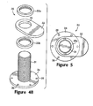
- Figure 3 is an elevational view of the weight positioning system.
- Figure 4A is a perspective view of the weight positioning system.
- Figure 4B is an exploded perspective view of the weight positioning system.
- Figure 5 is a top plan view of the weight positioning system.
- Figure 6A is a cut-away elevational view of the head that depicts a weight in a first position.
- Figure 6B is a cut-away elevational view of the head that depicts the weight in a second position.
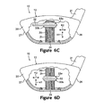
- Figure 6C is a cut-away elevational view of the head that depicts the weight in a third position.
- Figure 6D is a cut-away elevational view of the head that depicts the weight in a fourth position.
- Figure 7 is an exploded perspective view of another configuration of the weight positioning system.
- Figure 8A is a perspective view of various configurations of the weight positioning system.
- Figure 8B is an exploded perspective view of yet another configuration of the weight positioning system.
- Figure 9A is a partial perspective view of a second golf club having a head that incorporates the weight positioning system.
- Figure 9B is a cross-sectional view of a head of the second golf club, as defined by line 9B-9B in Figure 9A .
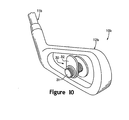
- Figure 10 is a partial perspective view of a third golf club having a head that incorporates the weight positioning system.
- Each golf club includes a head with a weight positioning system for varying a position of a center of gravity of the head.
- the weight positioning system has a support, and the weight positioning system has a weight that is movable along the support and around the support. Accordingly, the weight may be moved in three dimensions to vary the position of the center of gravity with respect to a face of the golf club.
- a golf club 10 in accordance with the present invention is disclosed in Figures 1-8 .
- the primary elements of golf club 10, which has the general configuration of a driver, are a shaft 11 and a head 12.
- Shaft 11 has a generally elongate configuration and may be formed of conventional materials, including graphite or steel.
- a grip may extend over a first end of shaft 11 to provide a comfortable and slip-resistant area for grasping golf club 10.
- Head 12 is secured to a second end of shaft 11 and is configured to engage a golf ball, thereby propelling the golf ball in an intended direction.
- head 12 provides golf club 10 with the structure of a driver.
- head 12 may provide golf club 10 with the structure of another type of golf club, including an iron or a putter, for example.
- Head 12 includes a shell 20 and a weight positioning system 30, as depicted in Figures 2A and 2B .
- Shell 20 is a partially hollow structure that defines an interior void for receiving system 30.
- the primary components of shell 20 are a hosel 21, a face 22, and an aperture 23.
- Hosel 21 is configured to couple with and securely attach to the second end of shaft 11.
- Face 22 is a generally planar surface that extends across shell 20 and provides a suitable area for engaging or contacting the golf ball.
- Aperture 23 is positioned in a lower portion of shell 20 and provides access to system 30.
- Suitable materials for shell 20 include any materials that are conventionally utilized for golf club heads, such as wood, steel, aluminum, or titanium.
- an individual grasps the first end of shaft 11 and swings golf club 10 such that head 12 traverses a generally arcuate path and impacts a golf ball.
- a portion of the inertia of golf club 10, and particularly the inertia of head 12 is then transferred to the golf ball and propels the golf ball toward an intended target.
- the position of a center of gravity of head 12 has an influence upon whether the golf ball curves right, curves left, or follows a generally straight route. More specifically, the golf ball follows a generally straight route when the center of gravity is positioned behind the point of engagement on face 22. When the center of gravity is spaced to one side of the point of engagement, however, the golf ball may follow a route that curves left or right.
- the position of the center of gravity of head 12 also has an influence upon whether the golf ball exhibits a boring or climbing trajectory, depending upon whether the center of gravity is spaced above or below the point of engagement on face 22.
- the golf ball may, for example, consistently curve right when, in fact, the individual intends to propel the golf ball along a straight route.
- Many conventional golf club heads have a fixed center of gravity intended to accommodate a majority of the individuals that play the game of golf.
- Head 12 includes system 30, thereby permitting the individual to selectively modify the position of the center of gravity of head 12 in a manner that conforms to the particular playing style and preferences of the individual. Accordingly, the individual may utilize system 30 to correct or modify the route of the golf ball by repositioning the center of gravity of head 12 with respect to face 22.
- System 30 is depicted individually in Figures 3-5 and includes a support 31, a weight 32, a pair of locking rings 33a and 33b, and a connector 34.
- the primary purpose of system 30 is to selectively modify the position of the center of gravity of head 12. This may be accomplished by generally moving weight 32 along support 31 and around support 31 to a desired location within shell 20.
- Locking rings 33a and 33b are also movable to secure weight 32 in the desired location, and connector 34 is utilized to connect system 30 to shell 20.
- Shell 20 receives system 30 such that support 31, weight 32, and locking rings 33a and 33b are positioned within shell 20.
- the center of gravity of head 12 is defined as an equilibrium point. More specifically, the center of gravity of head 12 is a point at which the entire weight of head 12 may be considered as concentrated so that, if supported at that point, head 12 would remain in static equilibrium in any position.
- Head 12 is a combination of two elements, namely shell 20 and system 30.
- the position of the center of gravity of head 12 is, therefore, dependent upon the properties of shell 20 and system 30. That is, the position of the center of gravity of head 12 is influenced by the weight of shell 20, the weight of system 30, the position of the center of gravity of shell 20, and the position of the center of gravity of system 30. Accordingly, changes in any of these properties of shell 20 and system 30 effectively change the position of the center of gravity of head 12.
- the weight of shell 20 and the position of the center of gravity of shell 20 are unchanging, or otherwise constant. Assume for purposes of the present discussion that the weight of system 30 is also constant. Accordingly, neither the weight of shell 20, the position of the center of gravity of shell 20, nor the weight of system 30 may act to change the position of the center of gravity of head 12.
- the position of the center of gravity of system 30 is, however, not constant due to changes in the position that result from moving weight 32 and locking rings 33a and 33b relative to support 31. Accordingly, moving weight 32 and locking rings 33a and 33b is an effective way to modify the position of the center of gravity of head 12. As will be discussed in greater detail below, the position of locking rings 33a and 33b is primarily dependent upon the position of weight 32. The position of the center of gravity of head 12 is, therefore, dependent upon the position of weight 32.
- Support 31 has a generally elongate shape and extends through aperture 23 to provide a securely-positioned foundation for weight 32.
- the configuration of support 31 is selected such that weight 32 may translate along support 31 and rotate around support 31 to modify the position of the center of gravity of head 12.
- support 31 is oriented vertically. Accordingly, weight 32 translates in the vertical direction to modify the position of the center of gravity of head 12 in the vertical direction. Weight 32 also rotates horizontally to modify the position of the center of gravity of head 12 in the vertical direction.
- support 31 may have a horizontal configuration, wherein weight 32 translates horizontally and rotates vertically to modify the position of the center of gravity of head 12 in the horizontal and vertical directions, respectively. Support 31 may also be oriented in any other manner. A benefit to the vertical and horizontal orientations, however, is that the individual will intuitively comprehend the manner in which movement of weight 32 affects the position of the center of gravity of head 12.
- Support 31 is depicted as having a cylindrical configuration, and weight 32 forms a circular opening 35.
- the diameter of opening 35 corresponds approximately with the diameter of support 31 such that weight 32 engages and extends around support 31.
- weight 32 may translate to any longitudinal position along support 31, and weight 32 may rotate to any angular position around weight 32.
- support 31 may have a hexagonal cross-section, rather than circular, and opening 35 may have a corresponding hexagonal shape. Rotation of weight 32 would, therefore, be limited to six positions.
- support 31 may have a shape with a greater or lesser number of sides. Although the non-circular shapes may appear limiting in that weight 32 may not rotate to an infinite number of angular positions, such shapes may be beneficial to prevent weight 32 from inadvertently rotating.
- the configuration of weight 32 is selected to induce a change in the position of the center of gravity of system 30 when weight 32 is rotated, thereby modifying the position of the center of gravity of head 12.
- One manner in which weight 32 may be structured to induce a change in the position of the center of gravity of system 30 is by positioning opening 35 in a spaced relationship with the position of the center of gravity of weight 32. That is, the center of gravity of weight 32 is offset from a centerline of support 31. If, for example, the center of gravity of weight 32 were positioned at a center of opening 35 and aligned with a center of support 31, then rotation of weight 32 would not affect the position of the center of gravity of weight 32.
- weight 32 has a generally elongate or elliptical shape, with support 31 and opening 35 being located adjacent an end of the elongate shape. In alternate embodiments, however, weight 32 may have any practical configuration that will induce a change in the position of the center of gravity of head 12 when weight 32 is rotated about support 31. Examples of suitable shapes for weight 32 include circular, triangular, square, or any other geometrical or non-geometrical shape where the center of opening 35 and the center of gravity of weight 32 are spaced from each other.
- Locking rings 33a and 33b are positioned on opposite sides of weight 32 and provide a locking mechanism for securing a position of weight 32 relative to support 31. As depicted in the figures, locking ring 33a is positioned above weight 32, and locking ring 33b is positioned below weight 32. Each of locking rings 33a and 33b are threaded to correspond with threads formed in support 31. Accordingly, locking rings 33a and 33b may be rotated to securely engage opposite sides of weight 32. Locking rings 33a and 33b may also be rotated in an opposite direction to disengage weight 32 and permit weight 32 to move relative to support 31. Locking rings 33a and 33b provide one example of a locking mechanism that may be utilized to secure the position of weight 32 relative to support 31. Within the scope of the present invention, however, a variety of other locking mechanisms may be utilized.
- Connector 34 is positioned on an end of support 31 and may be formed integral with support 31, or may be separately formed and subsequently joined with support 31. As depicted in the figures, connector 34 is a generally circular and planar structure that joins system 30 to shell 20. Connector 34 includes a plurality of bores 36 that correspond with a plurality of bores 24 extending around aperture 23. In order to secure system 30 to shell 20, bores 36 are aligned with bores 24 and a plurality of fasteners 25, such as screws, are positioned therethrough. Within the scope of the present invention, however, connector 34 may have any configuration that joins system 30 to shell 20.
- Suitable materials for system 30 include polymers, metals, ceramics, or composite materials, for example.
- the effect upon the position of the center of gravity of head 12 depends upon the relative weights of head 12 and weight 32. If, for example, weight 32 has a relatively small mass, then the change in position of the center of gravity of head 12 will be relatively small. Similarly, a weight 32 with a relatively large mass will have a relatively large effect upon the change in position of the center of gravity of head 12.
- weight 32 may be formed from a variety of materials, such as polymers or various metals, to impart the desired amount of change in position of the center of gravity of head 12.
- suitable materials for support 31 include metals such as aluminum or titanium.
- suitable materials for weight 32 include, therefore, high-density materials such as steel, tungsten, or bismuth, or composite materials with a high-density material concentrated away from support 31.
- Weight 32 is not the only movable component of system 30. Locking rings 33a and 33b also move with weight 32. Accordingly, locking rings 33a and 33b also affect the position of the center of gravity of head 12. In order to minimize the effects of locking rings 33a and 33b, the material selected for locking rings 33a and 33b may be significantly lighter than the material selected for weight 32.
- weight 32 may be formed from steel or another metal, whereas locking rings 33a and 33b may be formed from a polymer.
- weight 32 is depicted as being located toward a lower portion of support 31 and on a side of support 31 that faces a heel side 26 of shell 20.
- system 30 may be removed from shell 20 and locking rings 33a and 33b may be moved out of contact with weight 32.
- Weight 32 may then be moved upward to a different position, and locking rings 33a and 33b may again be placed in contact with opposite sides of weight 32.
- System 30 is then replaced within shell 20, as depicted in Figure 6B .
- Moving weight 32 upward in the vertical direction has the effect of also moving the center of gravity of head 12 upward in the vertical direction. Whereas weight 32 moved a significant distance along support 31, the center of gravity of head 12 moved a comparatively minor amount.
- the rationale behind the comparatively small movement of the center of gravity of head 12 is that weight 32 has an appreciable but small effect upon the position of the center of gravity of head 12.
- the position of the center of gravity of head 12 is influenced by the weight of shell 20, the weight of system 30, the position of the center of gravity of shell 20, and the position of the center of gravity of system 30.
- the position of weight 32 is only one of many factors, therefore, that have an effect upon the position of the center of gravity of head 12.
- Moving the center of gravity of head 12 upward in the vertical direction alters the position of the center of gravity with respect to face 22.
- the position of the center of gravity of head 12 also has an influence upon whether the golf ball exhibits an arcing or a low, flat trajectory, depending upon whether the center of gravity is spaced above or below the point of engagement on face 22. Accordingly, moving weight 32 in the vertical direction with respect to face 22 may be utilized to change the trajectory of the ball.
- system 30 may be removed from shell 20 and locking rings 33a and 33b may be moved out of contact with weight 32. Weight 32 may then be moved around to a side of support 31 that faces a toe side 27 of shell 20, and locking rings 33a and 33b may again be placed in contact with opposite sides of weight 32. System 30 is then replaced within shell 20, as depicted in Figure 6C .
- Moving weight 32 in the horizontal direction had the effect of also moving the center of gravity of head 12 in the horizontal direction. As with the vertical movement, the center of gravity of head 12 moved a relatively minor amount in the horizontal direction when compared to the overall movement of weight 32.
- One benefit of system 30 is that weight 32 is independently movable in the vertical direction and independently movable in the horizontal direction to vary a position of the center of gravity of head 12. The adjustment occurring between Figures 6A and 6B moved the center of gravity of head 12 in only the vertical direction. Similarly, the adjustment occurring between Figures 6B and 6C moved the center of gravity of head 12 in only the horizontal direction.
- Moving the center of gravity of head 12 upward in the horizontal direction also alters the position of the center of gravity with respect to face 22.
- the position of a center of gravity of head 12 has an influence upon whether the golf ball curves right, curves left, or follows a generally straight route, depending upon whether the center of gravity is spaced right or left of the point of engagement on face 22.
- moving weight 32 in the horizontal direction with respect to face 22 may be utilized to change the trajectory of the ball.
- system 30 may be removed from shell 20 and locking rings 33a and 33b may be moved out of contact with weight 32. Weight 32 may then be moved downward and to an area that is generally centered between heel side 26 and toe side 27, and locking rings 33a and 33b may again be placed in contact with opposite sides of weight 32. System 30 is then replaced within shell 20, as depicted in Figure 6D . Moving weight 32 in the vertical and horizontal directions has the effect of also moving the center of gravity of head 12 in the vertical and horizontal directions with respect to face 22.
- the center of gravity of head 12 may be repositioned solely in the vertical direction, repositioned solely in the horizontal direction, or repositioned simultaneously in both the vertical and horizontal directions with respect to face 22.
- weight 32 moves along support 31 and around support 31.
- Weight 32 is, therefore, movable in three dimensions with respect to support 31 to vary a position of the center of gravity of head 12 with respect to face 22.
- An advantage of system 30 in this regard is that this variability with respect to the repositioning of the center of gravity of head 12 is achieved with a single support 31 and weight 32.
- system 30 may be modified in many respects within the scope of the present invention.
- a series of indentations may be formed in the exterior surface of support 31, and corresponding protrusions may be formed in opening 35, as depicted in Figure 7 .
- the indentations and protrusions may be utilized to limit the rotational positioning of weight 32 to defined locations around support 31.
- Scales 37a and 37b may also be placed upon the exterior surface of support 31 to provide a frame of reference regarding the position of weight 32.
- weight 32 may be replaced by alternate weights 38 that each have a different shape or a different mass, for example. Replacing weight 32 with an alternate weight 38 may be utilized to increase or decrease the degree to which the center of gravity of head 12 is repositioned.
- the various weights 38 may have various configurations from generally rectangular to triangular or ovoid, for example.
- system 30 may have a weight 38 having the configuration depicted in Figure 8B .
- This weight 38 has a pair of arms that extend outward from opening 35 and a pair of masses secured to ends of the arms. As depicted, the arms are angled with respect to each other, but may extend outward in opposite directions. Accordingly, the specific configuration of weight 32 or weights 38 may vary significantly within the scope of the present invention.
- Golf club 10 is depicted and discussed above as a driver. Other types of golf clubs may also incorporate weight positioning system 30.
- a golf club 10a having the general configuration of a putter is disclosed. Golf club 10a includes a shaft 11a and a head 12a, with weight positioning system 30 being located on an interior portion of head 12a.
- system 30 may be utilized to alter a position of a center of gravity of head 12a, thereby moving the center of gravity with respect to a face 22a of head 12a. Accordingly, the position of the center of gravity of head 12a may be modified by the individual to meet the unique requirements or playing style of the individual.
- a golf club 10b having the general configuration of an iron is disclosed in Figure 10 .
- Golf club 10b includes a shaft 11b and a head 12b.
- weight positioning system 30 is located on an exterior portion of head 12b, rather than on an interior portion. System 30 is, therefore, exposed and more accessible to the individual, thereby facilitating changes in the position of a center of gravity of head 12b.
- a further difference between golf club 10b and golf clubs 10 and 10a relates to the orientation of system 30.
- support 31 is secured is a substantially vertical orientation.
- support 31 is secured is a substantially horizontal orientation and extends rearward from a back of head 12b.
- support 31 may be oriented perpendicularly with respect to a face of head 12b.
Landscapes
- Health & Medical Sciences (AREA)
- General Health & Medical Sciences (AREA)
- Physical Education & Sports Medicine (AREA)
- Life Sciences & Earth Sciences (AREA)
- Engineering & Computer Science (AREA)
- Wood Science & Technology (AREA)
- Golf Clubs (AREA)
Abstract
Description
- The present invention relates to the game of golf. The invention concerns, more particularly, a weight positioning system for modifying a position of a center of gravity of a golf club head.
- The formal origins of the game of golf, one of the oldest international sports, dates to the 16th century at The Royal and Ancient Golf Club at St. Andrews, located in Scotland. During successive centuries, the game of golf has gained and maintained a populous following due to inherent challenges of the game, a prestigious reputation, and its suitability for relaxation.
- Growth in the number of individuals playing the game of golf provides an incentive for manufacturers of golf equipment, which includes golf clubs, balls, footwear, and bags, to improve upon the various features and characteristics of the golf equipment. Golf equipment has, therefore, evolved over time to provide enhanced performance and suitability for a wide range of playing abilities and styles. Many traditional golf balls, for example, included a wound, twine core and a balata rubber cover. More modem golf balls, however, may incorporate a solid core formed of polybutadiene, titanium, nickel, or cobalt, and a cover formed of ionomeric resin, surlyn, or polyurethane. Similarly, footwear intended for the game of golf traditionally utilized sharp, metallic spikes that provided a high degree of traction at the expense of damaging floors and other walking surfaces. In response, modem footwear incorporates polymer structures that provide a comparable degree of traction without damaging walking surfaces. Advances in golf club technology are also of particular interest to sporting goods manufacturers. Golf club shafts, for example, were often fashioned from wood, and are commonly formed of metal or graphite materials today. Whereas golf club heads of drivers were also fashioned from ' wood, modem drivers generally utilize heads formed of metals, such as steel, aluminum, or titanium.
- A golf club head generally includes a substantially planar contact area for engaging a golf ball and propelling the golf ball in an intended direction. One factor that determines whether the golf ball is propelled in the intended direction relates to a position of a center of gravity of the golf club head. When the center of gravity is positioned behind the point of engagement on the contact surface, the golf ball follows a generally straight route. When the center of gravity is spaced to a side of the point of engagement, however, the golf ball may follow a route that curves left or right, which is often referred to as a hook or a slice. Similarly, when the center of gravity is spaced above or below the point of engagement, the route of the golf ball may exhibit a boring or climbing trajectory.
- Most conventional golf club heads have a fixed center of gravity intended to accommodate a majority of the individuals that play the game of golf. Although golf club heads with a fixed center of gravity are popular among individuals that play the game of golf, systems permitting an individual to adjust or reposition the center of gravity have been proposed. A first type of positioning system involves a translating weight.
U.S. Patent Number 6,277,032 to Smith , for example, discloses a rotatable screw extending through a void in the golf club head. Rotation of the screw induces a weight to move along the length of the screw, thereby altering the position of the center of gravity. A second type of positioning system is disclosed inU.S. Patent Number 5,916,042 to Reimers and generally involves a rotatable, eccentric weight that rotates around a central axis to alter the position of the center of gravity. A third type of positioning system, as disclosed inU.S. Patent Number 5,385,348 to Wargo , includes a removable element of the golf club head that may be replaced by an alternate element having a different weight or moved to a different position of the golf club head, thereby altering the position of the center of gravity. - The present invention is a golf club head that includes a face and a weight positioning system. The face provides a contact area for engaging a golf ball, and the weight positioning system includes a support and a weight. The weight is movable along the support and around the support to vary a position of a center of gravity of the golf club head with respect to the face.
- The weight, in another aspect of the invention, may be independently movable along the support, and the weight may be independently movable around the support. That is, the weight may be moved along the support without affecting the angular position of the weight with respect to the support. Similarly, the weight may be moved around the support without affecting the longitudinal position of the weight with respect to the support. This configuration permits the center of gravity to be repositioned in only the first direction, only the second direction, or in a combination of the first and second directions. The weight may have many configurations within the scope of the present invention, including a generally rounded shape, a rectangular shape, a triangular shape, or a shape that includes a pair of arms with masses suspended on ends of the arms.
- In addition to the weight and the support, the weight positioning system may also include a locking mechanism and a connector. The locking mechanism is utilized to secure a position of the weight relative to the support. A pair of locking rings, for example, positioned on opposite sides of the weight may be utilized as the locking mechanism. The connector is utilized to secure the weight positioning system to the golf club head.
- The advantages and features of novelty characterizing the present invention are pointed out with particularity in the appended claims. To gain an improved understanding of the advantages and features of novelty, however, reference may be made to the following descriptive matter and accompanying drawings that describe and illustrate various embodiments and concepts related to the invention.
- The foregoing Summary of the Invention, as well as the following Detailed Description of the Invention, will be better understood when read in conjunction with the accompanying drawings.
-
Figure 1 is an elevational view of a first golf club having a head with a weight positioning system in accordance with the present invention. -
Figure 2A is a perspective view of the head. -
Figure 2B is an exploded perspective view of the head. -
Figure 3 is an elevational view of the weight positioning system. -
Figure 4A is a perspective view of the weight positioning system. -
Figure 4B is an exploded perspective view of the weight positioning system. -
Figure 5 is a top plan view of the weight positioning system. -
Figure 6A is a cut-away elevational view of the head that depicts a weight in a first position. -
Figure 6B is a cut-away elevational view of the head that depicts the weight in a second position. -
Figure 6C is a cut-away elevational view of the head that depicts the weight in a third position. -
Figure 6D is a cut-away elevational view of the head that depicts the weight in a fourth position. -
Figure 7 is an exploded perspective view of another configuration of the weight positioning system. -
Figure 8A is a perspective view of various configurations of the weight positioning system. -
Figure 8B is an exploded perspective view of yet another configuration of the weight positioning system. -
Figure 9A is a partial perspective view of a second golf club having a head that incorporates the weight positioning system. -
Figure 9B is a cross-sectional view of a head of the second golf club, as defined byline 9B-9B inFigure 9A . -
Figure 10 is a partial perspective view of a third golf club having a head that incorporates the weight positioning system. - The following discussion and accompanying figures disclose various golf clubs in accordance with the present invention, which may be a driver, a putter, or an iron, for example. Each golf club includes a head with a weight positioning system for varying a position of a center of gravity of the head. The weight positioning system has a support, and the weight positioning system has a weight that is movable along the support and around the support. Accordingly, the weight may be moved in three dimensions to vary the position of the center of gravity with respect to a face of the golf club.
- A
golf club 10 in accordance with the present invention is disclosed inFigures 1-8 . The primary elements ofgolf club 10, which has the general configuration of a driver, are ashaft 11 and ahead 12.Shaft 11 has a generally elongate configuration and may be formed of conventional materials, including graphite or steel. A grip may extend over a first end ofshaft 11 to provide a comfortable and slip-resistant area for graspinggolf club 10.Head 12 is secured to a second end ofshaft 11 and is configured to engage a golf ball, thereby propelling the golf ball in an intended direction. As depicted in the figures,head 12 providesgolf club 10 with the structure of a driver. Within the scope of the present invention, however,head 12 may providegolf club 10 with the structure of another type of golf club, including an iron or a putter, for example. -
Head 12 includes ashell 20 and aweight positioning system 30, as depicted inFigures 2A and2B .Shell 20 is a partially hollow structure that defines an interior void for receivingsystem 30. The primary components ofshell 20 are ahosel 21, aface 22, and anaperture 23.Hosel 21 is configured to couple with and securely attach to the second end ofshaft 11.Face 22 is a generally planar surface that extends acrossshell 20 and provides a suitable area for engaging or contacting the golf ball.Aperture 23 is positioned in a lower portion ofshell 20 and provides access tosystem 30. Suitable materials forshell 20 include any materials that are conventionally utilized for golf club heads, such as wood, steel, aluminum, or titanium. - During the game of golf, an individual grasps the first end of
shaft 11 and swingsgolf club 10 such thathead 12 traverses a generally arcuate path and impacts a golf ball. A portion of the inertia ofgolf club 10, and particularly the inertia ofhead 12, is then transferred to the golf ball and propels the golf ball toward an intended target. The position of a center of gravity ofhead 12 has an influence upon whether the golf ball curves right, curves left, or follows a generally straight route. More specifically, the golf ball follows a generally straight route when the center of gravity is positioned behind the point of engagement onface 22. When the center of gravity is spaced to one side of the point of engagement, however, the golf ball may follow a route that curves left or right. The position of the center of gravity ofhead 12 also has an influence upon whether the golf ball exhibits a boring or climbing trajectory, depending upon whether the center of gravity is spaced above or below the point of engagement onface 22. - Although the concepts behind utilizing a golf club to propel a golf ball toward an intended target appear simplistic, the actual practice of propelling the golf ball in an intended manner is exceedingly complex. The golf ball may, for example, consistently curve right when, in fact, the individual intends to propel the golf ball along a straight route. Many conventional golf club heads have a fixed center of gravity intended to accommodate a majority of the individuals that play the game of golf.
Head 12, however, includessystem 30, thereby permitting the individual to selectively modify the position of the center of gravity ofhead 12 in a manner that conforms to the particular playing style and preferences of the individual. Accordingly, the individual may utilizesystem 30 to correct or modify the route of the golf ball by repositioning the center of gravity ofhead 12 with respect to face 22. -
System 30 is depicted individually inFigures 3-5 and includes asupport 31, aweight 32, a pair of lockingrings connector 34. The primary purpose ofsystem 30 is to selectively modify the position of the center of gravity ofhead 12. This may be accomplished by generally movingweight 32 alongsupport 31 and aroundsupport 31 to a desired location withinshell 20. Locking rings 33a and 33b are also movable to secureweight 32 in the desired location, andconnector 34 is utilized to connectsystem 30 to shell 20.Shell 20 receivessystem 30 such thatsupport 31,weight 32, and lockingrings shell 20. - The center of gravity of
head 12, otherwise referred to as the center of mass, is defined as an equilibrium point. More specifically, the center of gravity ofhead 12 is a point at which the entire weight ofhead 12 may be considered as concentrated so that, if supported at that point,head 12 would remain in static equilibrium in any position.Head 12 is a combination of two elements, namely shell 20 andsystem 30. The position of the center of gravity ofhead 12 is, therefore, dependent upon the properties ofshell 20 andsystem 30. That is, the position of the center of gravity ofhead 12 is influenced by the weight ofshell 20, the weight ofsystem 30, the position of the center of gravity ofshell 20, and the position of the center of gravity ofsystem 30. Accordingly, changes in any of these properties ofshell 20 andsystem 30 effectively change the position of the center of gravity ofhead 12. - The weight of
shell 20 and the position of the center of gravity ofshell 20 are unchanging, or otherwise constant. Assume for purposes of the present discussion that the weight ofsystem 30 is also constant. Accordingly, neither the weight ofshell 20, the position of the center of gravity ofshell 20, nor the weight ofsystem 30 may act to change the position of the center of gravity ofhead 12. The position of the center of gravity ofsystem 30 is, however, not constant due to changes in the position that result from movingweight 32 and lockingrings weight 32 and lockingrings head 12. As will be discussed in greater detail below, the position of lockingrings weight 32. The position of the center of gravity ofhead 12 is, therefore, dependent upon the position ofweight 32. -
Support 31 has a generally elongate shape and extends throughaperture 23 to provide a securely-positioned foundation forweight 32. The configuration ofsupport 31 is selected such thatweight 32 may translate alongsupport 31 and rotate aroundsupport 31 to modify the position of the center of gravity ofhead 12. As depicted in the figures support 31 is oriented vertically. Accordingly,weight 32 translates in the vertical direction to modify the position of the center of gravity ofhead 12 in the vertical direction.Weight 32 also rotates horizontally to modify the position of the center of gravity ofhead 12 in the vertical direction. In alternate embodiments,support 31 may have a horizontal configuration, whereinweight 32 translates horizontally and rotates vertically to modify the position of the center of gravity ofhead 12 in the horizontal and vertical directions, respectively.Support 31 may also be oriented in any other manner. A benefit to the vertical and horizontal orientations, however, is that the individual will intuitively comprehend the manner in which movement ofweight 32 affects the position of the center of gravity ofhead 12. -
Support 31 is depicted as having a cylindrical configuration, andweight 32 forms acircular opening 35. The diameter of opening 35 corresponds approximately with the diameter ofsupport 31 such thatweight 32 engages and extends aroundsupport 31. In this configuration,weight 32 may translate to any longitudinal position alongsupport 31, andweight 32 may rotate to any angular position aroundweight 32. In alternate embodiments,support 31 may have a hexagonal cross-section, rather than circular, andopening 35 may have a corresponding hexagonal shape. Rotation ofweight 32 would, therefore, be limited to six positions. Similarly,support 31 may have a shape with a greater or lesser number of sides. Although the non-circular shapes may appear limiting in thatweight 32 may not rotate to an infinite number of angular positions, such shapes may be beneficial to preventweight 32 from inadvertently rotating. - The configuration of
weight 32 is selected to induce a change in the position of the center of gravity ofsystem 30 whenweight 32 is rotated, thereby modifying the position of the center of gravity ofhead 12. One manner in whichweight 32 may be structured to induce a change in the position of the center of gravity ofsystem 30 is by positioningopening 35 in a spaced relationship with the position of the center of gravity ofweight 32. That is, the center of gravity ofweight 32 is offset from a centerline ofsupport 31. If, for example, the center of gravity ofweight 32 were positioned at a center of opening 35 and aligned with a center ofsupport 31, then rotation ofweight 32 would not affect the position of the center of gravity ofweight 32. As depicted in the figures,weight 32 has a generally elongate or elliptical shape, withsupport 31 andopening 35 being located adjacent an end of the elongate shape. In alternate embodiments, however,weight 32 may have any practical configuration that will induce a change in the position of the center of gravity ofhead 12 whenweight 32 is rotated aboutsupport 31. Examples of suitable shapes forweight 32 include circular, triangular, square, or any other geometrical or non-geometrical shape where the center of opening 35 and the center of gravity ofweight 32 are spaced from each other. - Locking rings 33a and 33b are positioned on opposite sides of
weight 32 and provide a locking mechanism for securing a position ofweight 32 relative to support 31. As depicted in the figures, lockingring 33a is positioned aboveweight 32, and lockingring 33b is positioned belowweight 32. Each of lockingrings support 31. Accordingly, lockingrings weight 32. Locking rings 33a and 33b may also be rotated in an opposite direction to disengageweight 32 and permitweight 32 to move relative to support 31. Locking rings 33a and 33b provide one example of a locking mechanism that may be utilized to secure the position ofweight 32 relative to support 31. Within the scope of the present invention, however, a variety of other locking mechanisms may be utilized. -
Connector 34 is positioned on an end ofsupport 31 and may be formed integral withsupport 31, or may be separately formed and subsequently joined withsupport 31. As depicted in the figures,connector 34 is a generally circular and planar structure that joinssystem 30 to shell 20.Connector 34 includes a plurality ofbores 36 that correspond with a plurality ofbores 24 extending aroundaperture 23. In order to securesystem 30 to shell 20, bores 36 are aligned withbores 24 and a plurality offasteners 25, such as screws, are positioned therethrough. Within the scope of the present invention, however,connector 34 may have any configuration that joinssystem 30 to shell 20. - Suitable materials for
system 30 include polymers, metals, ceramics, or composite materials, for example. For a given change in position ofweight 32, the effect upon the position of the center of gravity ofhead 12 depends upon the relative weights ofhead 12 andweight 32. If, for example,weight 32 has a relatively small mass, then the change in position of the center of gravity ofhead 12 will be relatively small. Similarly, aweight 32 with a relatively large mass will have a relatively large effect upon the change in position of the center of gravity ofhead 12. Accordingly,weight 32 may be formed from a variety of materials, such as polymers or various metals, to impart the desired amount of change in position of the center of gravity ofhead 12. Examples of suitable materials forsupport 31 include metals such as aluminum or titanium. Examples of suitable materials forweight 32 include, therefore, high-density materials such as steel, tungsten, or bismuth, or composite materials with a high-density material concentrated away fromsupport 31. -
Weight 32 is not the only movable component ofsystem 30. Locking rings 33a and 33b also move withweight 32. Accordingly, lockingrings head 12. In order to minimize the effects of lockingrings rings weight 32. For example,weight 32 may be formed from steel or another metal, whereas lockingrings - The manner in which
system 30 is utilized to modify the position of the center of gravity ofhead 12 will now be discussed with reference toFigures 6A-6D . For purposes of reference inFigures 6A-6D , a double-headedarrow 41 is utilized to illustrate the vertical direction, another double-headedarrow 42 is utilized to illustrate the horizontal direction. - With reference to
Figure 6A ,weight 32 is depicted as being located toward a lower portion ofsupport 31 and on a side ofsupport 31 that faces aheel side 26 ofshell 20. Following the use ofgolf club 10, the individual may determine that moving the center of gravity ofhead 12 in the vertical direction would be beneficial. To accomplish this,system 30 may be removed fromshell 20 and lockingrings weight 32.Weight 32 may then be moved upward to a different position, and lockingrings weight 32.System 30 is then replaced withinshell 20, as depicted inFigure 6B . - Moving
weight 32 upward in the vertical direction has the effect of also moving the center of gravity ofhead 12 upward in the vertical direction. Whereasweight 32 moved a significant distance alongsupport 31, the center of gravity ofhead 12 moved a comparatively minor amount. The rationale behind the comparatively small movement of the center of gravity ofhead 12 is thatweight 32 has an appreciable but small effect upon the position of the center of gravity ofhead 12. As discussed above, the position of the center of gravity ofhead 12 is influenced by the weight ofshell 20, the weight ofsystem 30, the position of the center of gravity ofshell 20, and the position of the center of gravity ofsystem 30. The position ofweight 32 is only one of many factors, therefore, that have an effect upon the position of the center of gravity ofhead 12. - Moving the center of gravity of
head 12 upward in the vertical direction alters the position of the center of gravity with respect to face 22. As discussed above, the position of the center of gravity ofhead 12 also has an influence upon whether the golf ball exhibits an arcing or a low, flat trajectory, depending upon whether the center of gravity is spaced above or below the point of engagement onface 22. Accordingly, movingweight 32 in the vertical direction with respect to face 22 may be utilized to change the trajectory of the ball. - Following continued use of
golf club 10, the individual may determine that moving the center of gravity ofhead 12 in the horizontal direction would be beneficial. As with the prior adjustment,system 30 may be removed fromshell 20 and lockingrings weight 32.Weight 32 may then be moved around to a side ofsupport 31 that faces atoe side 27 ofshell 20, and lockingrings weight 32.System 30 is then replaced withinshell 20, as depicted inFigure 6C . - Moving
weight 32 in the horizontal direction had the effect of also moving the center of gravity ofhead 12 in the horizontal direction. As with the vertical movement, the center of gravity ofhead 12 moved a relatively minor amount in the horizontal direction when compared to the overall movement ofweight 32. One benefit ofsystem 30 is thatweight 32 is independently movable in the vertical direction and independently movable in the horizontal direction to vary a position of the center of gravity ofhead 12. The adjustment occurring betweenFigures 6A and 6B moved the center of gravity ofhead 12 in only the vertical direction. Similarly, the adjustment occurring betweenFigures 6B and6C moved the center of gravity ofhead 12 in only the horizontal direction. By providing the individual with independent adjustability in the vertical and horizontal directions, greater control over the specific effect upon the route of the golf ball is achieved. - Moving the center of gravity of
head 12 upward in the horizontal direction also alters the position of the center of gravity with respect to face 22. As discussed above, the position of a center of gravity ofhead 12 has an influence upon whether the golf ball curves right, curves left, or follows a generally straight route, depending upon whether the center of gravity is spaced right or left of the point of engagement onface 22. Accordingly, movingweight 32 in the horizontal direction with respect to face 22 may be utilized to change the trajectory of the ball. - Although independent adjustability is beneficial, circumstances may arise wherein a repositioning of the center of gravity of
head 12 in both the vertical and horizontal directions is required. As with the prior adjustments,system 30 may be removed fromshell 20 and lockingrings weight 32.Weight 32 may then be moved downward and to an area that is generally centered betweenheel side 26 andtoe side 27, and lockingrings weight 32.System 30 is then replaced withinshell 20, as depicted inFigure 6D . Movingweight 32 in the vertical and horizontal directions has the effect of also moving the center of gravity ofhead 12 in the vertical and horizontal directions with respect to face 22. - Based upon the discussion above, the center of gravity of
head 12 may be repositioned solely in the vertical direction, repositioned solely in the horizontal direction, or repositioned simultaneously in both the vertical and horizontal directions with respect to face 22. In order to provide this variability,weight 32 moves alongsupport 31 and aroundsupport 31.Weight 32 is, therefore, movable in three dimensions with respect to support 31 to vary a position of the center of gravity ofhead 12 with respect to face 22. An advantage ofsystem 30 in this regard is that this variability with respect to the repositioning of the center of gravity ofhead 12 is achieved with asingle support 31 andweight 32. - The specific configuration of
system 30 disclosed above may be modified in many respects within the scope of the present invention. For example, a series of indentations may be formed in the exterior surface ofsupport 31, and corresponding protrusions may be formed inopening 35, as depicted inFigure 7 . The indentations and protrusions may be utilized to limit the rotational positioning ofweight 32 to defined locations aroundsupport 31.Scales support 31 to provide a frame of reference regarding the position ofweight 32. - In the above discussion the overall mass of
system 30, and particularly the mass ofweight 32, was a constant. In another embodiment of the present invention, which is depicted inFigure 8A ,weight 32 may be replaced byalternate weights 38 that each have a different shape or a different mass, for example. Replacingweight 32 with analternate weight 38 may be utilized to increase or decrease the degree to which the center of gravity ofhead 12 is repositioned. Thevarious weights 38 may have various configurations from generally rectangular to triangular or ovoid, for example. As an alternative to the various structures ofweight 32 andweights 38 that are disclosed inFigure 8A ,system 30 may have aweight 38 having the configuration depicted inFigure 8B . Thisweight 38 has a pair of arms that extend outward from opening 35 and a pair of masses secured to ends of the arms. As depicted, the arms are angled with respect to each other, but may extend outward in opposite directions. Accordingly, the specific configuration ofweight 32 orweights 38 may vary significantly within the scope of the present invention. -
Golf club 10 is depicted and discussed above as a driver. Other types of golf clubs may also incorporateweight positioning system 30. With reference toFigures 9A and 9B , agolf club 10a having the general configuration of a putter is disclosed.Golf club 10a includes a shaft 11a and ahead 12a, withweight positioning system 30 being located on an interior portion ofhead 12a. In a manner that is substantially similar to the process discussed above with respect togolf club 10,system 30 may be utilized to alter a position of a center of gravity ofhead 12a, thereby moving the center of gravity with respect to aface 22a ofhead 12a. Accordingly, the position of the center of gravity ofhead 12a may be modified by the individual to meet the unique requirements or playing style of the individual. - A
golf club 10b having the general configuration of an iron is disclosed inFigure 10 .Golf club 10b includes ashaft 11b and ahead 12b. In contrast withgolf club 10 andgolf club 10b,weight positioning system 30 is located on an exterior portion ofhead 12b, rather than on an interior portion.System 30 is, therefore, exposed and more accessible to the individual, thereby facilitating changes in the position of a center of gravity ofhead 12b. A further difference betweengolf club 10b andgolf clubs system 30. In both ofgolf clubs support 31 is secured is a substantially vertical orientation. Ingolf club 10b, however,support 31 is secured is a substantially horizontal orientation and extends rearward from a back ofhead 12b. In some embodiments,support 31 may be oriented perpendicularly with respect to a face ofhead 12b. - The present invention is disclosed above and in the accompanying drawings with reference to a variety of embodiments. The purpose served by the disclosure, however, is to provide an example of the various features and concepts related to the invention, not to limit the scope of the invention. One skilled in the relevant art will recognize that numerous variations and modifications may be made to the embodiments described above without departing from the scope of the present invention, as defined by the appended claims.
- 1. A golf club head comprising: a face that provides a contact area for engaging a golf ball; and a weight positioning system that includes a support and a weight, the weight being movable along the support and around the support to vary a position of a center of gravity of the golf club head with respect to the face.
- 2. The golf club head of clause 1, wherein the golf club head includes a shell, and the face is a portion of the shell.
- 3. The golf club head of
clause 2, wherein the shell defines an aperture, the weight positioning system being removable from an interior of the shell through the aperture. - 4. The golf club head of clause 3, wherein the aperture is positioned in a lower area of the shell.
- 5. The golf club head of
clause 2, wherein the weight positioning system includes a connector configured to connect the weight positioning system to the shell. - 6. The golf club head of clause 1, wherein the support is positioned in a substantially vertical orientation.
- 7. The golf club head of clause 1, wherein the weight positioning system includes a locking mechanism that secures a position of the weight relative to the support.
- 8. The golf club head of clause 7, wherein the locking mechanism is a pair of locking rings that extend around the support.
- 9. The golf club head of clause 8, wherein the support and the locking rings include corresponding threads.
- 10. The golf club head of clause 8, wherein the locking rings are positioned on opposite sides of the weight.
- 11. The golf club head of clause 1, wherein a center of gravity of the weight is offset from a centerline of the support.
- 12. The golf club head of clause 1, wherein the weight has an elliptical shape.
- 13. The golf club head of clause 1, wherein the weight defines an opening that extends at least partially around the support.
- 14. The golf club head of clause 13, wherein a center of gravity of the weight is offset from the opening.
- 15. The golf club head of clause 13, wherein one of an indentation and a protrusion extends along the support, and another of the indentation and the protrusion is positioned within the opening, the indentation receiving the protrusion to limit movement of the weight around the support.
- 16. The golf club head of clause 1, wherein the weight is independently movable along the support and independently movable around the support.
- 17. The golf club head of clause 1, wherein the weight positioning system includes at least one scale to determine a position of the weight relative to the support.
- 18. The golf club head of clause 1, wherein the weight is interchangeable with one of a plurality of alternate weights.
- 19. The golf club head of clause 18, wherein at least one of the alternate weights has a different mass than the weight.
- 20. The golf club head of clause 18, wherein at least one of the alternate weights has a different shape than the weight.
- 21. The golf club head of clause 1, wherein the weight positioning system is mounted on an exterior of the golf club head.
- 22. The golf club head of clause 1, wherein the weight includes a pair of arms that extend outward from the support, and a pair of masses are secured to the arms.
- 23. The golf club head of
clause 22, wherein the arms are angled with respect to each other. - 24. A golf club head comprising: a shell having a face that provides a contact area for engaging a golf ball; and a weight positioning system substantially located on an interior of the shell, the weight positioning system including: a support, and a weight movably-connected to the support, the weight being movable along the support to vary a position of a center of gravity of the golf club head in first direction with respect to the face, and the support being movable around the support to vary the position of the center of gravity of the golf club head in a second direction with respect to the face.
- 25. The golf club head of
clause 24, wherein the weight is independently movable along the support and independently movable around the support. - 26. The golf club head of
clause 24, wherein an aperture is positioned in a lower area of the shell, the weight positioning system being removable from the interior of the shell through the aperture. - 27. The. golf club head of
clause 24, wherein the weight positioning system includes a locking mechanism that secures a position of the weight relative to the support. - 28. The golf club head of
clause 27, wherein the locking mechanism is a pair of locking rings that extend around the support. - 29. The golf club head of clause 28, wherein the support and the locking rings include corresponding threads.
- 30. The golf club head of
clause 24, wherein a center of gravity of the weight is offset from a centerline of the support. - 31. The golf club head of
clause 24, wherein the weight defines an opening that extends at least partially around the support. - 32. The golf club head of
clause 31, wherein a center of gravity of the weight is offset from the opening. - 33. The golf club head of
clause 24, wherein one of an indentation and a protrusion extends along the support, and another of the indentation and the protrusion is positioned within an opening defined in the weight, the indentation receiving the protrusion to limit movement of the weight around the support. - 34. The golf club head of
clause 24, wherein the weight positioning system includes at least one scale to determine a position of the weight relative to the support. - 35. The golf club head of
clause 24, wherein the weight is interchangeable with one of a plurality of alternate weights. - 36. The golf club head of
clause 35, wherein at least one of the alternate weights has a different mass than the weight. - 37. The golf club head of
clause 35, wherein at least one of the alternate weights has a different shape than the weight. - 38. The golf club head of
clause 24, wherein the weight positioning system includes a connector configured to connect the weight positioning system to the shell. - 39. The golf club head of
clause 24, wherein the weight includes a pair of arms that extend outward from the support, and a pair of masses are secured to the arms. - 40. The golf club head of clause 39, wherein the arms are angled with respect to each other.
- 41. A golf club having an elongate shaft and a head positioned on an end of the shaft, the head comprising: a face that provides a contact area for engaging a golf ball; and a weight positioning system that includes: a support, a weight movably-connected to the support, the weight being independently movable along the support to vary a position of a center of gravity of the golf club head in first direction with respect to the face, and the weight being independently movable around the support to vary the position of the center of gravity of the golf club head in a second direction with respect to the face, and a locking mechanism to secure a position of the weight relative to the support.
- 42. The golf club of
clause 41, wherein the golf club head includes a shell, and the face is a portion of the shell. - 43. The golf club of
clause 42, wherein the shell defines an aperture, the weight positioning system being removable from an interior of the shell through the aperture. - 44. The golf club of clause 43, wherein the aperture is positioned in a lower area of the shell.
- 45. The golf club of
clause 41, wherein the locking mechanism is a pair of locking rings that extend around the support. - 46. The golf club of clause 45, wherein the support and the locking rings include corresponding threads.
- 47. The golf club of
clause 41, wherein a center of gravity of the weight is offset from a centerline of the support. - 48. The golf club of
clause 41, wherein the weight defines an opening that extends at least partially around the support. - 49. The golf club of clause 48, wherein a center of gravity of the weight is offset from the opening.
- 50. The golf club of clause 48, wherein one of an indentation and a protrusion extends along the support, and another of the indentation and the protrusion is positioned within the opening, the indentation receiving the protrusion to limit movement of the weight around the support.
- 51. The golf club of
clause 41, wherein the weight is interchangeable with one of a plurality of alternate weights. - 52. The golf club of clause 51, wherein at least one of the alternate weights has a different mass than the weight.
- 53. The golf club of clause 51, wherein at least one of the alternate weights has a different shape than the weight.
- 54. The golf club of
clause 41, wherein the weight positioning system is mounted on an exterior of the head. - 55. A golf club having an elongate shaft and a head positioned on an end of the shaft, the head comprising: a face that provides a contact area for engaging a golf ball; and a weight positioning system that includes a support and a weight, the weight being movable in three dimensions with respect to the support to vary a position of a center of gravity of the golf club head with respect to the face.
- 56. The golf club of clause 55, wherein the weight positioning system includes a locking mechanism that secures a position of the weight relative to the support.
- 57. The golf club of clause 55, wherein the locking mechanism is a pair of locking rings that extend around the support.
- 58. The golf club of clause 55, wherein a center of gravity of the weight is offset from a centerline of the support.
- 59. The golf club of clause 55, wherein the weight defines an opening that extends at least partially around the support.
- 60. The golf club of clause 59, wherein a center of gravity of the weight is offset from the opening.
- 61. The golf club of clause 55, wherein the weight is interchangeable with one of a plurality of alternate weights.
- 62. The golf club of clause 61, wherein at least one of the alternate weights has at least one of a different mass and a different shape than the weight.
- 63. The golf club of clause 55, wherein the weight positioning system is mounted on an exterior of the head.
- 64. A golf club head comprising: a face that provides a contact area for engaging a golf ball; and a weight positioning system that includes a support and a weight, the weight being movable in three dimensions with respect to the support to vary a position of a center of gravity of the golf club head with respect to the face.
- 65. The golf club head of clause 64, wherein the golf club head includes a shell, and the face is a portion of the shell.
- 66. The golf club head of clause 64, wherein the support is positioned in a substantially vertical orientation.
- 67. The golf club head of clause 64, wherein the weight positioning system includes a locking mechanism that secures a position of the weight relative to the support.
- 68. The golf club head of clause 64, wherein a center of gravity of the weight is offset from a centerline of the support.
- 69. The golf club head of clause 64, wherein the weight is independently movable along the support and independently movable around the support.
- 70. The golf club head of clause 64, wherein the weight includes a pair of arms that extend outward from the support, and a pair of masses are secured to the arms.
Claims (15)
- A golf club head comprising:a face that provides a contact area for engaging a golf ball; anda weight positioning system that includes a support and a weight, the weight being movable along the support and around the support to vary a position of a centre of gravity of the golf club head with respect to the face, wherein the weight defines an opening that extends at least partially around the support, and wherein the weight positioning system includes at least one scale to determine a position of the weight relative to the support.
- The golf club head of claim 1, wherein the weight has an elliptical shape.
- The golf club head of claim 1 or claim 2, wherein the scale is positioned on a surface of the support.
- The golf club head of any preceding claim, wherein a centre of gravity of the weight is offset from the opening.
- The golf club head of any preceding claim, wherein the weight is interchangeable with one of a plurality of alternate weights, and wherein preferably at least one of the alternate weights has a different mass or shape than the weight.
- The golf club head of any preceding claim, wherein the weight positioning system is mounted on an exterior of the golf club head.
- The golf club head of any preceding claim, wherein the support has a longitudinal axis extending along the length of the support, and wherein the at least one scale includes a first scale and a second scale, the first scale being orientated to extend in a direction substantially parallel to the longitudinal axis, and the second scale being orientated to extend in a direction substantially perpendicular to the longitudinal axis.
- The golf club head of claim 7, wherein the first scale determines a position of the weight along the support, and the second scale determines a position of the weight around support.
- The golf club head of claim 7, wherein an indentation extends along the support and in a direction parallel to the longitudinal axis of the support, and a protrusion is positioned within the opening, the indentation receiving the protrusion to limit movement of the weight around support.
- The golf club head of claim 9, wherein the scale is positioned within the indentation.
- The golf club head of any preceding claim, wherein the golf club head includes a shell, and the face is a portion of the shell.
- The golf club head of any preceding claim, wherein the weight positioning system is located within the shell.
- The golf club head of any preceding claim, wearing the longitudinal axis of the support is orientated substantially parallel to the face.
- The golf club head of any preceding claim, wherein the weight includes a pair of arms that extend outward from the support, and a pair of masses are secured to the arms.
- The golf club head of claim 14, wherein the arms are angled with respect to each other.
Applications Claiming Priority (2)
| Application Number | Priority Date | Filing Date | Title |
|---|---|---|---|
| US10/615,934 US7108609B2 (en) | 2003-07-10 | 2003-07-10 | Golf club having a weight positioning system |
| EP04754106.5A EP1644091B1 (en) | 2003-07-10 | 2004-06-24 | Golf club having a weight positioning system |
Related Parent Applications (2)
| Application Number | Title | Priority Date | Filing Date |
|---|---|---|---|
| EP04754106.5A Division-Into EP1644091B1 (en) | 2003-07-10 | 2004-06-24 | Golf club having a weight positioning system |
| EP04754106.5 Division | 2004-06-24 |
Publications (2)
| Publication Number | Publication Date |
|---|---|
| EP2260907A1 true EP2260907A1 (en) | 2010-12-15 |
| EP2260907B1 EP2260907B1 (en) | 2013-01-09 |
Family
ID=33564662
Family Applications (2)
| Application Number | Title | Priority Date | Filing Date |
|---|---|---|---|
| EP04754106.5A Expired - Lifetime EP1644091B1 (en) | 2003-07-10 | 2004-06-24 | Golf club having a weight positioning system |
| EP10184409A Expired - Lifetime EP2260907B1 (en) | 2003-07-10 | 2004-06-24 | Golf club having a weight positioning system |
Family Applications Before (1)
| Application Number | Title | Priority Date | Filing Date |
|---|---|---|---|
| EP04754106.5A Expired - Lifetime EP1644091B1 (en) | 2003-07-10 | 2004-06-24 | Golf club having a weight positioning system |
Country Status (4)
| Country | Link |
|---|---|
| US (1) | US7108609B2 (en) |
| EP (2) | EP1644091B1 (en) |
| JP (2) | JP2007527262A (en) |
| WO (1) | WO2005009548A1 (en) |
Families Citing this family (115)
| Publication number | Priority date | Publication date | Assignee | Title |
|---|---|---|---|---|
| US7128660B2 (en) * | 2000-05-19 | 2006-10-31 | Elizabeth P. Gillig Revocable Trust | Method of golf club performance enhancement and articles resultant therefrom |
| US8142308B2 (en) * | 2000-05-19 | 2012-03-27 | Triple Tee Golf, Inc. | System of golf club performance enhancement and articles resultant therefrom |
| US7004852B2 (en) | 2002-01-10 | 2006-02-28 | Dogleg Right Corporation | Customizable center-of-gravity golf club head |
| US7278343B2 (en) * | 2002-05-24 | 2007-10-09 | Vanden Heuvel Rick J | Apparatus for lap seaming floor coverings |
| US7186190B1 (en) * | 2002-11-08 | 2007-03-06 | Taylor Made Golf Company, Inc. | Golf club head having movable weights |
| US20100113181A1 (en) * | 2002-11-12 | 2010-05-06 | Vyatek Sports, Inc. | Multi-material golf clubhead |
| US7351161B2 (en) * | 2005-01-10 | 2008-04-01 | Adam Beach | Scientifically adaptable driver |
| US8938871B2 (en) | 2005-04-21 | 2015-01-27 | Cobra Golf Incorporated | Golf club head with high specific-gravity materials |
| US9393471B2 (en) | 2005-04-21 | 2016-07-19 | Cobra Golf Incorporated | Golf club head with removable component |
| US9421438B2 (en) | 2005-04-21 | 2016-08-23 | Cobra Golf Incorporated | Golf club head with accessible interior |
| US9440123B2 (en) | 2005-04-21 | 2016-09-13 | Cobra Golf Incorporated | Golf club head with accessible interior |
| US20130178306A1 (en) | 2005-04-21 | 2013-07-11 | Cobra Golf Incorporated | Golf club head with separable component |
| US8303433B2 (en) * | 2005-04-21 | 2012-11-06 | Cobra Golf Incorporated | Golf club head with moveable insert |
| US20060240907A1 (en) * | 2005-04-25 | 2006-10-26 | Mondher Latiri | Golf club head with adjustable center of mass |
| AR059066A1 (en) * | 2006-01-27 | 2008-03-12 | Amgen Inc | COMBINATIONS OF THE ANGIOPOYETINE INHIBITOR -2 (ANG2) AND THE VASCULAR ENDOTELIAL GROWTH FACTOR INHIBITOR (VEGF) |
| US7744487B2 (en) * | 2006-03-06 | 2010-06-29 | Nike, Inc. | Golf clubs and golf club heads having feel altering systems |
| US7566276B2 (en) | 2006-04-14 | 2009-07-28 | Dogleg Right Corporation | Multi-piece putter head having an insert |
| US9700764B2 (en) * | 2006-08-03 | 2017-07-11 | Vandette B. Carter | Golf club with adjustable center of gravity head |
| TWM316090U (en) * | 2006-08-09 | 2007-08-01 | Fu Sheng Ind Co Ltd | Detachable weight structure for golf club head |
| US20080132353A1 (en) * | 2006-12-01 | 2008-06-05 | Pen-Long Hsiao | Weight adjustable golf club head |
| JP5049099B2 (en) * | 2007-11-07 | 2012-10-17 | ダンロップスポーツ株式会社 | Golf club head |
| US8409031B2 (en) * | 2008-01-17 | 2013-04-02 | Nike, Inc. | Golf clubs and golf club heads with adjustable center of gravity and moment of inertia characteristics |
| US9233282B2 (en) * | 2008-01-17 | 2016-01-12 | Nike, Inc. | Golf clubs and gold club heads with adjustable center of gravity and moment of inertia characteristics |
| US7988568B2 (en) * | 2008-01-17 | 2011-08-02 | Nike, Inc. | Golf clubs and golf club heads with adjustable center of gravity and moment of inertia characteristics |
| US7806782B2 (en) * | 2008-02-12 | 2010-10-05 | Nike, Inc. | Golf clubs and golf club heads having adjustable weight members |
| US7758451B2 (en) * | 2008-02-25 | 2010-07-20 | Cobra Golf, Inc | Weight adjusting structure of golf club head |
| US7967700B2 (en) * | 2008-10-30 | 2011-06-28 | Nike, Inc. | Golf club head or other ball striking device having adjustable stiffened face portion |
| JP5329208B2 (en) * | 2008-12-25 | 2013-10-30 | ブリヂストンスポーツ株式会社 | Putter head |
| US20100190566A1 (en) * | 2009-01-29 | 2010-07-29 | Haack Scott G | Golf putter |
| JP2011005167A (en) * | 2009-06-29 | 2011-01-13 | Bridgestone Sports Co Ltd | Golf club head |
| US8197357B1 (en) * | 2009-12-16 | 2012-06-12 | Callaway Golf Company | Golf club head with composite weight port |
| US8444506B2 (en) * | 2009-12-16 | 2013-05-21 | Callaway Golf Company | Golf club head with composite weight port |
| US9259625B2 (en) | 2009-12-23 | 2016-02-16 | Taylor Made Golf Company, Inc. | Golf club head |
| US9561413B2 (en) | 2009-12-23 | 2017-02-07 | Taylor Made Golf Company, Inc. | Golf club head |
| US8491416B1 (en) | 2010-08-20 | 2013-07-23 | Callaway Golf Company | Golf club head |
| US9440126B2 (en) * | 2010-09-30 | 2016-09-13 | Robert Boyd | Golf club and golf club head structures |
| US9573027B2 (en) | 2011-08-23 | 2017-02-21 | Sri Sports Limited | Weight member for a golf club head |
| CN107583254B (en) | 2011-08-23 | 2020-03-27 | 耐克创新有限合伙公司 | Golf club head with cavity |
| US9956463B2 (en) | 2011-11-30 | 2018-05-01 | Nike, Inc. | Golf clubs and golf club heads |
| US9072948B2 (en) | 2011-11-30 | 2015-07-07 | Nike, Inc. | Golf club head or other ball striking device utilizing energy transfer |
| US9943733B2 (en) | 2011-11-30 | 2018-04-17 | Nike, Inc. | Golf clubs and golf club heads |
| US9855477B2 (en) | 2011-11-30 | 2018-01-02 | Nike, Inc. | Golf clubs and golf club heads |
| US9901792B2 (en) | 2011-11-30 | 2018-02-27 | Nike, Inc. | Golf clubs and golf club heads |
| JP2013123439A (en) * | 2011-12-13 | 2013-06-24 | Dunlop Sports Co Ltd | Golf club head |
| US8403771B1 (en) * | 2011-12-21 | 2013-03-26 | Callaway Gold Company | Golf club head |
| US9079078B2 (en) | 2011-12-29 | 2015-07-14 | Taylor Made Golf Company, Inc. | Golf club head |
| US20130324299A1 (en) * | 2012-06-05 | 2013-12-05 | Cobra Golf Incorporated | Golf club with vertically adjustable center of gravity |
| US8956244B1 (en) | 2012-06-08 | 2015-02-17 | Callaway Golf Company | Golf club head with center of gravity adjustability |
| US9211453B1 (en) * | 2012-11-16 | 2015-12-15 | Callaway Golf Company | Golf club head with adjustable center of gravity |
| US8834294B1 (en) | 2012-06-08 | 2014-09-16 | Callaway Golf Company | Golf club head with center of gravity adjustability |
| US9067110B1 (en) | 2012-06-08 | 2015-06-30 | Callaway Golf Company | Golf club head with center of gravity adjustability |
| US9889349B1 (en) | 2012-06-27 | 2018-02-13 | Callway Golf Company | Golf club head having stress-reducing structures |
| US10589154B2 (en) * | 2012-06-27 | 2020-03-17 | Callaway Golf Company | Golf club head having adjustable stress-reducing structures |
| US9486677B1 (en) | 2013-03-07 | 2016-11-08 | Callaway Golf Company | Weighted golf club head having composite tubes |
| US9687702B1 (en) | 2012-06-27 | 2017-06-27 | Callaway Golf Company | Golf club head with structural columns |
| US10238933B1 (en) * | 2012-06-27 | 2019-03-26 | Callaway Golf Company | Golf club head having adjustable stress-reducing structures |
| US9776058B2 (en) * | 2012-06-27 | 2017-10-03 | Callaway Golf Company | Golf club head having optimized ball speed to CT relationship |
| US9821199B1 (en) | 2012-06-27 | 2017-11-21 | Callaway Golf Company | Golf club head having stress-reducing tubes |
| US20170151474A1 (en) * | 2012-06-27 | 2017-06-01 | Callaway Golf Company | Golf Club Head With Structural Columns |
| US20170144034A1 (en) * | 2012-06-27 | 2017-05-25 | Callaway Golf Company | Golf Club Head With Structural Columns |
| US9694257B1 (en) | 2012-06-27 | 2017-07-04 | Callaway Golf Company | Golf club head with structural columns |
| JP5956861B2 (en) * | 2012-07-17 | 2016-07-27 | ダンロップスポーツ株式会社 | Golf club head |
| US11617927B2 (en) | 2012-09-18 | 2023-04-04 | Taylor Made Golf Company, Inc. | Golf club head |
| USD697155S1 (en) * | 2012-11-15 | 2014-01-07 | Taylor Made Golf Company, Inc. | Golf club head |
| US9675856B1 (en) | 2012-11-16 | 2017-06-13 | Callaway Golf Company | Golf club head with adjustable center of gravity |
| US8696491B1 (en) | 2012-11-16 | 2014-04-15 | Callaway Golf Company | Golf club head with adjustable center of gravity |
| US8968116B1 (en) * | 2012-12-27 | 2015-03-03 | Callaway Golf Company | Golf club head with adjustable characteristics |
| US9220957B1 (en) * | 2012-12-27 | 2015-12-29 | Callaway Golf Company | Golf club head with adjustable characteristics |
| US9205311B2 (en) * | 2013-03-04 | 2015-12-08 | Karsten Manufacturing Corporation | Club head with sole mass element and related method |
| US9623294B1 (en) * | 2014-01-24 | 2017-04-18 | Callaway Golf Company | Golf club head with adjustable weighting |
| US10016662B1 (en) | 2014-05-21 | 2018-07-10 | Taylor Made Golf Company, Inc. | Golf club |
| US9757630B2 (en) | 2015-05-20 | 2017-09-12 | Taylor Made Golf Company, Inc. | Golf club heads |
| US10046211B2 (en) | 2014-05-29 | 2018-08-14 | Nike, Inc. | Golf clubs and golf club heads |
| US9931548B2 (en) | 2014-06-20 | 2018-04-03 | Karsten Manufacturing Corporation | Golf club head with polymeric insert |
| US9339701B2 (en) * | 2014-06-20 | 2016-05-17 | Nike, Inc. | Golf club with removable weight |
| US9975022B2 (en) | 2014-06-20 | 2018-05-22 | Karsten Manufacturing Corporation | Golf club with weight receiving polymeric insert |
| JP6430728B2 (en) * | 2014-06-30 | 2018-11-28 | 住友ゴム工業株式会社 | Golf club head |
| US20160074720A1 (en) * | 2014-09-16 | 2016-03-17 | Dunlop Sports Company Limited | Golf club head with interior weight adjustable in multiple directions |
| US10413785B2 (en) * | 2014-12-11 | 2019-09-17 | Karsten Manufacturing Corporation | Golf club head or other ball striking device with removable face and/or internal support structure |
| US10130849B2 (en) * | 2015-05-29 | 2018-11-20 | Karsten Manufacturing Corporation | Golf clubs and golf club heads |
| US9597561B1 (en) | 2015-06-30 | 2017-03-21 | Callaway Golf Company | Golf club head having face stress-reduction features |
| JP6484141B2 (en) * | 2015-08-18 | 2019-03-13 | 住友ゴム工業株式会社 | Golf club head |
| US9873029B1 (en) | 2016-08-24 | 2018-01-23 | Wilson Sporting Goods Co. | Golf club head |
| US10486042B1 (en) * | 2018-05-17 | 2019-11-26 | Callaway Golf Company | Golf club head with adjustable center of gravity |
| US10653926B2 (en) | 2018-07-23 | 2020-05-19 | Taylor Made Golf Company, Inc. | Golf club heads |
| US12472409B2 (en) * | 2019-04-18 | 2025-11-18 | Acushnet Company | Golf club having an adjustable weight assembly |
| US12678669B2 (en) * | 2019-04-18 | 2026-07-14 | Acushnet Company | Golf club having an adjustable weight assembly |
| US12569730B2 (en) | 2019-04-18 | 2026-03-10 | Acushnet Company | Golf club having an adjustable weight assembly |
| US20240299814A1 (en) * | 2019-04-18 | 2024-09-12 | Acushnet Company | Golf club having an adjustable weight assembly |
| US10695628B1 (en) | 2019-04-18 | 2020-06-30 | Acushnet Company | Golf club having an adjustable weight assembly |
| US10926143B2 (en) * | 2019-04-18 | 2021-02-23 | Acushnet Company | Golf club having an adjustable weight assembly |
| US11090536B2 (en) * | 2019-04-18 | 2021-08-17 | Acushnet Company | Golf club having an adjustable weight assembly |
| US12649091B2 (en) | 2019-04-18 | 2026-06-09 | Acushnet Company | Golf club having an adjustable weight assembly |
| US10918917B2 (en) * | 2019-04-18 | 2021-02-16 | Acushnet Company | Golf club having an adjustable weight assembly |
| US11229827B2 (en) * | 2019-04-18 | 2022-01-25 | Acushnet Company | Golf club having an adjustable weight assembly |
| US11497974B2 (en) | 2019-04-18 | 2022-11-15 | Acushnet Company | Golf club having an adjustable weight assembly |
| US11439879B2 (en) * | 2019-04-18 | 2022-09-13 | Acushnet Company | Golf club having an adjustable weight assembly |
| US12415120B2 (en) * | 2019-04-18 | 2025-09-16 | Acushnet Company | Golf club having an adjustable weight assembly |
| US12478843B2 (en) | 2019-04-18 | 2025-11-25 | Acushnet Company | Golf club having an adjustable weight assembly |
| US11413510B2 (en) * | 2019-05-10 | 2022-08-16 | Taylor Made Golf Company, Inc. | Golf club |
| US12576315B2 (en) * | 2019-05-10 | 2026-03-17 | Taylor Made Golf Company, Inc. | Clubheads for iron-type golf clubs |
| US11458374B2 (en) * | 2019-05-10 | 2022-10-04 | Taylor Made Golf Company, Inc. | Golf club |
| US11400351B2 (en) | 2019-05-10 | 2022-08-02 | Taylor Made Golf Company, Inc. | Golf club |
| US11406882B2 (en) * | 2019-05-10 | 2022-08-09 | Taylor Made Golf Company, Inc. | Iron-type golf club head |
| US11351429B2 (en) | 2019-05-10 | 2022-06-07 | Taylor Made Golf Company, Inc. | Golf club |
| US10596428B1 (en) * | 2019-08-14 | 2020-03-24 | Clive Roy Rumble | Golf club |
| US10835791B1 (en) * | 2020-03-02 | 2020-11-17 | Callaway Golf Company | Golf club head with adjustable sole weight |
| JP7111379B2 (en) * | 2020-03-11 | 2022-08-02 | 株式会社貴翔 | Swing practice equipment for fast-twitch training to increase flight distance in golf |
| US12702906B2 (en) * | 2020-04-08 | 2026-08-11 | Acushnet Company | Modular golf club including an adjustable weight assembly |
| US20240316420A1 (en) * | 2020-04-08 | 2024-09-26 | Acushnet Company | Modular golf club head including an adjustable weight assembly |
| US11759685B2 (en) | 2020-12-28 | 2023-09-19 | Taylor Made Golf Company, Inc. | Golf club heads |
| US11998810B1 (en) * | 2021-09-20 | 2024-06-04 | Cobra Golf Incorporated | Reversible sole plate for a golf club head |
| US12661562B2 (en) * | 2022-08-30 | 2026-06-23 | Acushnet Company | Golf club including swivelable weight |
| US12661561B2 (en) * | 2022-08-30 | 2026-06-23 | Acushnet Company | Golf club head with adjustable viewable weighting |
| US12654073B2 (en) * | 2023-10-10 | 2026-06-16 | Acushnet Company | Modular golf club head including a weight assembly having adjustable components |
Citations (5)
| Publication number | Priority date | Publication date | Assignee | Title |
|---|---|---|---|---|
| DE3711964A1 (en) * | 1987-04-09 | 1988-10-27 | Handtmann Albert Elteka Gmbh | GOLF CLUB WITH A CHANGING GRAVITY CENTER |
| US5385348A (en) | 1993-11-15 | 1995-01-31 | Wargo; Elmer | Method and system for providing custom designed golf clubs having replaceable swing weight inserts |
| GB2327889A (en) * | 1997-08-09 | 1999-02-10 | Wang Samw Hong Jen | Adjustably weighted golf club head |
| US5916042A (en) | 1995-10-11 | 1999-06-29 | Reimers; Eric W. | Adjustable balance weighting system for golf clubs |
| US6277032B1 (en) | 1999-07-29 | 2001-08-21 | Vigor C. Smith | Movable weight golf clubs |
Family Cites Families (38)
| Publication number | Priority date | Publication date | Assignee | Title |
|---|---|---|---|---|
| GB194823A (en) | 1921-12-23 | 1923-03-22 | James Hamilton Stirling | Improvements in or relating to golf clubs and the like |
| US1582956A (en) * | 1921-12-29 | 1926-05-04 | American Can Co | Key-opening can |
| US1518316A (en) | 1922-12-14 | 1924-12-09 | Robert W Ellingham | Golf club |
| US1518318A (en) * | 1923-12-06 | 1924-12-09 | Anna L Wilson | Fire escape |
| US1562956A (en) | 1925-03-23 | 1925-11-24 | Alfred A Guerne | Golf-club head |
| US2098445A (en) * | 1937-03-11 | 1937-11-09 | William L Wettlaufer | Golf club |
| US2171383A (en) * | 1938-10-12 | 1939-08-29 | William L Wettlaufer | Golf club head |
| US2163091A (en) | 1938-12-19 | 1939-06-20 | Hillerich & Bradsby Co Inc | Adjustable weighting device for golf club heads |
| US2460445A (en) | 1948-04-19 | 1949-02-01 | Charles W Bigler | Adjustable weight for golf club heads |
| US3199874A (en) * | 1963-02-25 | 1965-08-10 | John J Blasing | Golf club head including liquid mercury in rotatable turntable |
| US3610630A (en) | 1969-10-21 | 1971-10-05 | Cecil C Glover | Golf club head with weight adjusting means |
| US3759527A (en) | 1971-04-19 | 1973-09-18 | W Witherspoon | Golf club |
| US3743297A (en) | 1972-06-05 | 1973-07-03 | E Dennis | Golf swing practice club |
| JPS5276759U (en) * | 1975-12-03 | 1977-06-08 | ||
| US4052075A (en) | 1976-01-08 | 1977-10-04 | Daly C Robert | Golf club |
| US4195842A (en) | 1976-08-05 | 1980-04-01 | Coleman Marvin W | Golf club and process for making same |
| JPS6013163U (en) * | 1983-07-04 | 1985-01-29 | 大前 二三夫 | Head structure with variable center of gravity device for golf wood clubs |
| US4895371A (en) | 1988-07-29 | 1990-01-23 | Bushner Gerald F | Golf putter |
| US4962932A (en) * | 1989-09-06 | 1990-10-16 | Anderson Thomas G | Golf putter head with adjustable weight cylinder |
| JPH0419911U (en) * | 1990-05-10 | 1992-02-19 | ||
| US5121922A (en) | 1991-06-14 | 1992-06-16 | Harsh Sr Ronald L | Golf club head weight modification apparatus |
| US5253869A (en) * | 1991-11-27 | 1993-10-19 | Dingle Craig B | Golf putter |
| US5429356A (en) * | 1991-11-27 | 1995-07-04 | Bill-Ding Technology, Inc. | Golf putter |
| JPH0628844A (en) * | 1992-07-11 | 1994-02-04 | Hitachi Ltd | Semiconductor storage device |
| JP2968655B2 (en) * | 1992-10-08 | 1999-10-25 | 三菱マテリアル株式会社 | Golf club head manufacturing method |
| US5421577A (en) * | 1993-04-15 | 1995-06-06 | Kobayashi; Kenji | Metallic golf clubhead |
| JPH06296716A (en) * | 1993-04-16 | 1994-10-25 | Endo Seisakusho:Kk | Metal golf club head |
| JPH0928844A (en) * | 1995-07-14 | 1997-02-04 | Yokohama Rubber Co Ltd:The | Golf club |
| US5571053A (en) | 1995-08-14 | 1996-11-05 | Lane; Stephen P. | Cantilever-weighted golf putter |
| US5683309A (en) | 1995-10-11 | 1997-11-04 | Reimers; Eric W. | Adjustable balance weighting system for golf clubs |
| US5688189A (en) | 1995-11-03 | 1997-11-18 | Bland; Bertram Alvin | Golf putter |
| US6149533A (en) | 1996-09-13 | 2000-11-21 | Finn; Charles A. | Golf club |
| US6514154B1 (en) * | 1996-09-13 | 2003-02-04 | Charles A. Finn | Golf club having adjustable weights and readily removable and replaceable shaft |
| US6077173A (en) | 1997-12-12 | 2000-06-20 | Tom Stites & Associates, Inc. | Iron-type golf club head |
| US6015354A (en) | 1998-03-05 | 2000-01-18 | Ahn; Stephen C. | Golf club with adjustable total weight, center of gravity and balance |
| US6113508A (en) * | 1998-08-18 | 2000-09-05 | Alliance Design And Development Group | Adjusting stiffness and flexibility in sports equipment |
| US6089994A (en) | 1998-09-11 | 2000-07-18 | Sun; Donald J. C. | Golf club head with selective weighting device |
| JP3009657B1 (en) * | 1998-11-10 | 2000-02-14 | 株式会社ナニワ製作所 | Golf club putter head |
-
2003
- 2003-07-10 US US10/615,934 patent/US7108609B2/en not_active Expired - Lifetime
-
2004
- 2004-06-24 JP JP2006518629A patent/JP2007527262A/en not_active Withdrawn
- 2004-06-24 EP EP04754106.5A patent/EP1644091B1/en not_active Expired - Lifetime
- 2004-06-24 WO PCT/US2004/017421 patent/WO2005009548A1/en not_active Ceased
- 2004-06-24 EP EP10184409A patent/EP2260907B1/en not_active Expired - Lifetime
-
2011
- 2011-01-13 JP JP2011004441A patent/JP5342570B2/en not_active Expired - Fee Related
Patent Citations (5)
| Publication number | Priority date | Publication date | Assignee | Title |
|---|---|---|---|---|
| DE3711964A1 (en) * | 1987-04-09 | 1988-10-27 | Handtmann Albert Elteka Gmbh | GOLF CLUB WITH A CHANGING GRAVITY CENTER |
| US5385348A (en) | 1993-11-15 | 1995-01-31 | Wargo; Elmer | Method and system for providing custom designed golf clubs having replaceable swing weight inserts |
| US5916042A (en) | 1995-10-11 | 1999-06-29 | Reimers; Eric W. | Adjustable balance weighting system for golf clubs |
| GB2327889A (en) * | 1997-08-09 | 1999-02-10 | Wang Samw Hong Jen | Adjustably weighted golf club head |
| US6277032B1 (en) | 1999-07-29 | 2001-08-21 | Vigor C. Smith | Movable weight golf clubs |
Also Published As
| Publication number | Publication date |
|---|---|
| EP2260907B1 (en) | 2013-01-09 |
| JP2007527262A (en) | 2007-09-27 |
| US20050009625A1 (en) | 2005-01-13 |
| WO2005009548A1 (en) | 2005-02-03 |
| JP2011092763A (en) | 2011-05-12 |
| JP5342570B2 (en) | 2013-11-13 |
| EP1644091B1 (en) | 2015-01-28 |
| US7108609B2 (en) | 2006-09-19 |
| EP1644091A1 (en) | 2006-04-12 |
Similar Documents
| Publication | Publication Date | Title |
|---|---|---|
| EP2260907B1 (en) | Golf club having a weight positioning system | |
| US10744380B2 (en) | Golf clubs and golf club heads | |
| US6962537B2 (en) | Mini-face blade putter | |
| US7399233B2 (en) | Golf putter with aiming mark | |
| US8409031B2 (en) | Golf clubs and golf club heads with adjustable center of gravity and moment of inertia characteristics | |
| US4932658A (en) | Golf club head | |
| EP2429665B1 (en) | Golf club head or other ball striking device having a reinforced or localized stiffened face portion | |
| US4919431A (en) | Golf club head | |
| US20080146372A1 (en) | Adjustable putter head | |
| JPH119742A (en) | Golf club head | |
| US9233282B2 (en) | Golf clubs and gold club heads with adjustable center of gravity and moment of inertia characteristics | |
| US6682439B2 (en) | Multi-string putter face with separate and variable tension capabilities and multiple position shaft with adjustable shaft angle capabilities | |
| US7066830B2 (en) | Golf club with improved head | |
| JPS6110712Y2 (en) | ||
| AU2001100301A4 (en) | Improvements relating to golf clubs | |
| JP2002325866A (en) | Golf club head |
Legal Events
| Date | Code | Title | Description |
|---|---|---|---|
| PUAI | Public reference made under article 153(3) epc to a published international application that has entered the european phase |
Free format text: ORIGINAL CODE: 0009012 |
|
| AC | Divisional application: reference to earlier application |
Ref document number: 1644091 Country of ref document: EP Kind code of ref document: P |
|
| AK | Designated contracting states |
Kind code of ref document: A1 Designated state(s): AT BE BG CH CY CZ DE DK EE ES FI FR GB GR HU IE IT LI LU MC NL PL PT RO SE SI SK TR |
|
| 17P | Request for examination filed |
Effective date: 20110614 |
|
| 17Q | First examination report despatched |
Effective date: 20111115 |
|
| GRAP | Despatch of communication of intention to grant a patent |
Free format text: ORIGINAL CODE: EPIDOSNIGR1 |
|
| GRAS | Grant fee paid |
Free format text: ORIGINAL CODE: EPIDOSNIGR3 |
|
| GRAA | (expected) grant |
Free format text: ORIGINAL CODE: 0009210 |
|
| AC | Divisional application: reference to earlier application |
Ref document number: 1644091 Country of ref document: EP Kind code of ref document: P |
|
| AK | Designated contracting states |
Kind code of ref document: B1 Designated state(s): AT BE BG CH CY CZ DE DK EE ES FI FR GB GR HU IE IT LI LU MC NL PL PT RO SE SI SK TR |
|
| REG | Reference to a national code |
Ref country code: GB Ref legal event code: FG4D |
|
| REG | Reference to a national code |
Ref country code: CH Ref legal event code: EP Ref country code: AT Ref legal event code: REF Ref document number: 592393 Country of ref document: AT Kind code of ref document: T Effective date: 20130115 |
|
| REG | Reference to a national code |
Ref country code: IE Ref legal event code: FG4D |
|
| REG | Reference to a national code |
Ref country code: DE Ref legal event code: R096 Ref document number: 602004040770 Country of ref document: DE Effective date: 20130314 |
|
| REG | Reference to a national code |
Ref country code: SE Ref legal event code: TRGR |
|
| PG25 | Lapsed in a contracting state [announced via postgrant information from national office to epo] |
Ref country code: SI Free format text: LAPSE BECAUSE OF FAILURE TO SUBMIT A TRANSLATION OF THE DESCRIPTION OR TO PAY THE FEE WITHIN THE PRESCRIBED TIME-LIMIT Effective date: 20130109 |
|
| REG | Reference to a national code |
Ref country code: NL Ref legal event code: VDEP Effective date: 20130109 |
|
| REG | Reference to a national code |
Ref country code: AT Ref legal event code: MK05 Ref document number: 592393 Country of ref document: AT Kind code of ref document: T Effective date: 20130109 |
|
| PG25 | Lapsed in a contracting state [announced via postgrant information from national office to epo] |
Ref country code: BE Free format text: LAPSE BECAUSE OF FAILURE TO SUBMIT A TRANSLATION OF THE DESCRIPTION OR TO PAY THE FEE WITHIN THE PRESCRIBED TIME-LIMIT Effective date: 20130109 Ref country code: BG Free format text: LAPSE BECAUSE OF FAILURE TO SUBMIT A TRANSLATION OF THE DESCRIPTION OR TO PAY THE FEE WITHIN THE PRESCRIBED TIME-LIMIT Effective date: 20130409 Ref country code: AT Free format text: LAPSE BECAUSE OF FAILURE TO SUBMIT A TRANSLATION OF THE DESCRIPTION OR TO PAY THE FEE WITHIN THE PRESCRIBED TIME-LIMIT Effective date: 20130109 Ref country code: ES Free format text: LAPSE BECAUSE OF FAILURE TO SUBMIT A TRANSLATION OF THE DESCRIPTION OR TO PAY THE FEE WITHIN THE PRESCRIBED TIME-LIMIT Effective date: 20130420 |
|
| PG25 | Lapsed in a contracting state [announced via postgrant information from national office to epo] |
Ref country code: GR Free format text: LAPSE BECAUSE OF FAILURE TO SUBMIT A TRANSLATION OF THE DESCRIPTION OR TO PAY THE FEE WITHIN THE PRESCRIBED TIME-LIMIT Effective date: 20130410 Ref country code: NL Free format text: LAPSE BECAUSE OF FAILURE TO SUBMIT A TRANSLATION OF THE DESCRIPTION OR TO PAY THE FEE WITHIN THE PRESCRIBED TIME-LIMIT Effective date: 20130109 Ref country code: PL Free format text: LAPSE BECAUSE OF FAILURE TO SUBMIT A TRANSLATION OF THE DESCRIPTION OR TO PAY THE FEE WITHIN THE PRESCRIBED TIME-LIMIT Effective date: 20130109 Ref country code: FI Free format text: LAPSE BECAUSE OF FAILURE TO SUBMIT A TRANSLATION OF THE DESCRIPTION OR TO PAY THE FEE WITHIN THE PRESCRIBED TIME-LIMIT Effective date: 20130109 Ref country code: PT Free format text: LAPSE BECAUSE OF FAILURE TO SUBMIT A TRANSLATION OF THE DESCRIPTION OR TO PAY THE FEE WITHIN THE PRESCRIBED TIME-LIMIT Effective date: 20130509 |
|
| PG25 | Lapsed in a contracting state [announced via postgrant information from national office to epo] |
Ref country code: DK Free format text: LAPSE BECAUSE OF FAILURE TO SUBMIT A TRANSLATION OF THE DESCRIPTION OR TO PAY THE FEE WITHIN THE PRESCRIBED TIME-LIMIT Effective date: 20130109 Ref country code: EE Free format text: LAPSE BECAUSE OF FAILURE TO SUBMIT A TRANSLATION OF THE DESCRIPTION OR TO PAY THE FEE WITHIN THE PRESCRIBED TIME-LIMIT Effective date: 20130109 Ref country code: CZ Free format text: LAPSE BECAUSE OF FAILURE TO SUBMIT A TRANSLATION OF THE DESCRIPTION OR TO PAY THE FEE WITHIN THE PRESCRIBED TIME-LIMIT Effective date: 20130109 Ref country code: RO Free format text: LAPSE BECAUSE OF FAILURE TO SUBMIT A TRANSLATION OF THE DESCRIPTION OR TO PAY THE FEE WITHIN THE PRESCRIBED TIME-LIMIT Effective date: 20130109 Ref country code: SK Free format text: LAPSE BECAUSE OF FAILURE TO SUBMIT A TRANSLATION OF THE DESCRIPTION OR TO PAY THE FEE WITHIN THE PRESCRIBED TIME-LIMIT Effective date: 20130109 |
|
| PLBE | No opposition filed within time limit |
Free format text: ORIGINAL CODE: 0009261 |
|
| STAA | Information on the status of an ep patent application or granted ep patent |
Free format text: STATUS: NO OPPOSITION FILED WITHIN TIME LIMIT |
|
| PG25 | Lapsed in a contracting state [announced via postgrant information from national office to epo] |
Ref country code: CY Free format text: LAPSE BECAUSE OF FAILURE TO SUBMIT A TRANSLATION OF THE DESCRIPTION OR TO PAY THE FEE WITHIN THE PRESCRIBED TIME-LIMIT Effective date: 20130109 |
|
| 26N | No opposition filed |
Effective date: 20131010 |
|
| PG25 | Lapsed in a contracting state [announced via postgrant information from national office to epo] |
Ref country code: IT Free format text: LAPSE BECAUSE OF FAILURE TO SUBMIT A TRANSLATION OF THE DESCRIPTION OR TO PAY THE FEE WITHIN THE PRESCRIBED TIME-LIMIT Effective date: 20130109 |
|
| REG | Reference to a national code |
Ref country code: DE Ref legal event code: R097 Ref document number: 602004040770 Country of ref document: DE Effective date: 20131010 |
|
| PG25 | Lapsed in a contracting state [announced via postgrant information from national office to epo] |
Ref country code: SE Free format text: LAPSE BECAUSE OF NON-PAYMENT OF DUE FEES Effective date: 20130625 Ref country code: MC Free format text: LAPSE BECAUSE OF FAILURE TO SUBMIT A TRANSLATION OF THE DESCRIPTION OR TO PAY THE FEE WITHIN THE PRESCRIBED TIME-LIMIT Effective date: 20130109 |
|
| REG | Reference to a national code |
Ref country code: CH Ref legal event code: PL |
|
| REG | Reference to a national code |
Ref country code: SE Ref legal event code: EUG |
|
| REG | Reference to a national code |
Ref country code: IE Ref legal event code: MM4A |
|
| PG25 | Lapsed in a contracting state [announced via postgrant information from national office to epo] |
Ref country code: LI Free format text: LAPSE BECAUSE OF NON-PAYMENT OF DUE FEES Effective date: 20130630 Ref country code: IE Free format text: LAPSE BECAUSE OF NON-PAYMENT OF DUE FEES Effective date: 20130624 Ref country code: CH Free format text: LAPSE BECAUSE OF NON-PAYMENT OF DUE FEES Effective date: 20130630 |
|
| REG | Reference to a national code |
Ref country code: GB Ref legal event code: 732E Free format text: REGISTERED BETWEEN 20140626 AND 20140702 |
|
| REG | Reference to a national code |
Ref country code: DE Ref legal event code: R082 Ref document number: 602004040770 Country of ref document: DE Representative=s name: KOTITSCHKE & HEURUNG PARTNERSCHAFT MBB PATENT-, DE |
|
| REG | Reference to a national code |
Ref country code: DE Ref legal event code: R082 Ref document number: 602004040770 Country of ref document: DE Representative=s name: DR. RALF KOTITSCHKE, DE Effective date: 20150401 Ref country code: DE Ref legal event code: R081 Ref document number: 602004040770 Country of ref document: DE Owner name: NIKE INNOVATE C.V. (KOMMANDITGESELLSCHAFT NIED, US Free format text: FORMER OWNER: NIKE INTERNATIONAL LTD., BEAVERTON, OREG., US Effective date: 20150401 Ref country code: DE Ref legal event code: R082 Ref document number: 602004040770 Country of ref document: DE Representative=s name: KOTITSCHKE & HEURUNG PARTNERSCHAFT MBB PATENT-, DE Effective date: 20150401 Ref country code: DE Ref legal event code: R082 Ref document number: 602004040770 Country of ref document: DE Representative=s name: KOTITSCHKE & HEURUNG PARTNERSCHAFT MBB, DE Effective date: 20150401 |
|
| REG | Reference to a national code |
Ref country code: FR Ref legal event code: TP Owner name: NIKE INNOVATE C.V., US Effective date: 20150420 |
|
| PG25 | Lapsed in a contracting state [announced via postgrant information from national office to epo] |
Ref country code: TR Free format text: LAPSE BECAUSE OF FAILURE TO SUBMIT A TRANSLATION OF THE DESCRIPTION OR TO PAY THE FEE WITHIN THE PRESCRIBED TIME-LIMIT Effective date: 20130109 |
|
| PG25 | Lapsed in a contracting state [announced via postgrant information from national office to epo] |
Ref country code: HU Free format text: LAPSE BECAUSE OF FAILURE TO SUBMIT A TRANSLATION OF THE DESCRIPTION OR TO PAY THE FEE WITHIN THE PRESCRIBED TIME-LIMIT; INVALID AB INITIO Effective date: 20040624 Ref country code: LU Free format text: LAPSE BECAUSE OF NON-PAYMENT OF DUE FEES Effective date: 20130624 |
|
| REG | Reference to a national code |
Ref country code: FR Ref legal event code: PLFP Year of fee payment: 13 |
|
| PGFP | Annual fee paid to national office [announced via postgrant information from national office to epo] |
Ref country code: DE Payment date: 20160622 Year of fee payment: 13 |
|
| PGFP | Annual fee paid to national office [announced via postgrant information from national office to epo] |
Ref country code: SE Payment date: 20160613 Year of fee payment: 13 Ref country code: FR Payment date: 20160516 Year of fee payment: 13 |
|
| REG | Reference to a national code |
Ref country code: DE Ref legal event code: R119 Ref document number: 602004040770 Country of ref document: DE |
|
| REG | Reference to a national code |
Ref country code: FR Ref legal event code: ST Effective date: 20180228 |
|
| PG25 | Lapsed in a contracting state [announced via postgrant information from national office to epo] |
Ref country code: DE Free format text: LAPSE BECAUSE OF NON-PAYMENT OF DUE FEES Effective date: 20180103 |
|
| PG25 | Lapsed in a contracting state [announced via postgrant information from national office to epo] |
Ref country code: FR Free format text: LAPSE BECAUSE OF NON-PAYMENT OF DUE FEES Effective date: 20170630 |
|
| REG | Reference to a national code |
Ref country code: GB Ref legal event code: 732E Free format text: REGISTERED BETWEEN 20180830 AND 20180905 |
|
| PGFP | Annual fee paid to national office [announced via postgrant information from national office to epo] |
Ref country code: GB Payment date: 20200629 Year of fee payment: 17 |
|
| GBPC | Gb: european patent ceased through non-payment of renewal fee |
Effective date: 20210624 |
|
| PG25 | Lapsed in a contracting state [announced via postgrant information from national office to epo] |
Ref country code: GB Free format text: LAPSE BECAUSE OF NON-PAYMENT OF DUE FEES Effective date: 20210624 |