EP2260596B1 - Verbesserungen in bezug auf optische netzwerke - Google Patents
Verbesserungen in bezug auf optische netzwerke Download PDFInfo
- Publication number
- EP2260596B1 EP2260596B1 EP08735991A EP08735991A EP2260596B1 EP 2260596 B1 EP2260596 B1 EP 2260596B1 EP 08735991 A EP08735991 A EP 08735991A EP 08735991 A EP08735991 A EP 08735991A EP 2260596 B1 EP2260596 B1 EP 2260596B1
- Authority
- EP
- European Patent Office
- Prior art keywords
- optical
- data
- optical signal
- signal
- amplifier
- Prior art date
- Legal status (The legal status is an assumption and is not a legal conclusion. Google has not performed a legal analysis and makes no representation as to the accuracy of the status listed.)
- Not-in-force
Links
- 230000003287 optical effect Effects 0.000 title claims description 191
- 238000011144 upstream manufacturing Methods 0.000 claims description 61
- 238000000034 method Methods 0.000 claims description 55
- 230000005540 biological transmission Effects 0.000 claims description 27
- 238000004891 communication Methods 0.000 claims description 17
- 239000004065 semiconductor Substances 0.000 claims description 9
- 241000206607 Porphyra umbilicalis Species 0.000 claims 2
- 239000013307 optical fiber Substances 0.000 description 20
- 239000006185 dispersion Substances 0.000 description 14
- 230000035945 sensitivity Effects 0.000 description 11
- 239000000835 fiber Substances 0.000 description 10
- 230000008901 benefit Effects 0.000 description 8
- 238000001228 spectrum Methods 0.000 description 7
- 238000010586 diagram Methods 0.000 description 4
- 230000000694 effects Effects 0.000 description 3
- RYGMFSIKBFXOCR-UHFFFAOYSA-N Copper Chemical compound [Cu] RYGMFSIKBFXOCR-UHFFFAOYSA-N 0.000 description 2
- 239000000969 carrier Substances 0.000 description 2
- 229910052802 copper Inorganic materials 0.000 description 2
- 239000010949 copper Substances 0.000 description 2
- 230000006735 deficit Effects 0.000 description 2
- 238000005259 measurement Methods 0.000 description 2
- 230000008569 process Effects 0.000 description 2
- 229910052691 Erbium Inorganic materials 0.000 description 1
- 230000003321 amplification Effects 0.000 description 1
- 230000002457 bidirectional effect Effects 0.000 description 1
- 230000008033 biological extinction Effects 0.000 description 1
- 230000033228 biological regulation Effects 0.000 description 1
- 230000015556 catabolic process Effects 0.000 description 1
- 238000012512 characterization method Methods 0.000 description 1
- 230000008878 coupling Effects 0.000 description 1
- 238000010168 coupling process Methods 0.000 description 1
- 238000005859 coupling reaction Methods 0.000 description 1
- 230000001419 dependent effect Effects 0.000 description 1
- 238000005516 engineering process Methods 0.000 description 1
- UYAHIZSMUZPPFV-UHFFFAOYSA-N erbium Chemical compound [Er] UYAHIZSMUZPPFV-UHFFFAOYSA-N 0.000 description 1
- 238000002474 experimental method Methods 0.000 description 1
- 238000002347 injection Methods 0.000 description 1
- 239000007924 injection Substances 0.000 description 1
- 238000009434 installation Methods 0.000 description 1
- 238000012423 maintenance Methods 0.000 description 1
- 238000004519 manufacturing process Methods 0.000 description 1
- 238000012544 monitoring process Methods 0.000 description 1
- 238000003199 nucleic acid amplification method Methods 0.000 description 1
- 230000010287 polarization Effects 0.000 description 1
- 238000011084 recovery Methods 0.000 description 1
- 230000009467 reduction Effects 0.000 description 1
- 238000002310 reflectometry Methods 0.000 description 1
- 229920006395 saturated elastomer Polymers 0.000 description 1
- 230000002269 spontaneous effect Effects 0.000 description 1
- 230000006641 stabilisation Effects 0.000 description 1
- 238000011105 stabilization Methods 0.000 description 1
Images


Classifications
-
- H—ELECTRICITY
- H04—ELECTRIC COMMUNICATION TECHNIQUE
- H04B—TRANSMISSION
- H04B10/00—Transmission systems employing electromagnetic waves other than radio-waves, e.g. infrared, visible or ultraviolet light, or employing corpuscular radiation, e.g. quantum communication
- H04B10/25—Arrangements specific to fibre transmission
- H04B10/2587—Arrangements specific to fibre transmission using a single light source for multiple stations
-
- H—ELECTRICITY
- H04—ELECTRIC COMMUNICATION TECHNIQUE
- H04J—MULTIPLEX COMMUNICATION
- H04J14/00—Optical multiplex systems
- H04J14/02—Wavelength-division multiplex systems
-
- H—ELECTRICITY
- H04—ELECTRIC COMMUNICATION TECHNIQUE
- H04J—MULTIPLEX COMMUNICATION
- H04J14/00—Optical multiplex systems
- H04J14/02—Wavelength-division multiplex systems
- H04J14/0227—Operation, administration, maintenance or provisioning [OAMP] of WDM networks, e.g. media access, routing or wavelength allocation
- H04J14/0241—Wavelength allocation for communications one-to-one, e.g. unicasting wavelengths
- H04J14/0242—Wavelength allocation for communications one-to-one, e.g. unicasting wavelengths in WDM-PON
- H04J14/0245—Wavelength allocation for communications one-to-one, e.g. unicasting wavelengths in WDM-PON for downstream transmission, e.g. optical line terminal [OLT] to ONU
- H04J14/0246—Wavelength allocation for communications one-to-one, e.g. unicasting wavelengths in WDM-PON for downstream transmission, e.g. optical line terminal [OLT] to ONU using one wavelength per ONU
-
- H—ELECTRICITY
- H04—ELECTRIC COMMUNICATION TECHNIQUE
- H04J—MULTIPLEX COMMUNICATION
- H04J14/00—Optical multiplex systems
- H04J14/02—Wavelength-division multiplex systems
- H04J14/0227—Operation, administration, maintenance or provisioning [OAMP] of WDM networks, e.g. media access, routing or wavelength allocation
- H04J14/0241—Wavelength allocation for communications one-to-one, e.g. unicasting wavelengths
- H04J14/0242—Wavelength allocation for communications one-to-one, e.g. unicasting wavelengths in WDM-PON
- H04J14/0245—Wavelength allocation for communications one-to-one, e.g. unicasting wavelengths in WDM-PON for downstream transmission, e.g. optical line terminal [OLT] to ONU
- H04J14/0247—Sharing one wavelength for at least a group of ONUs
-
- H—ELECTRICITY
- H04—ELECTRIC COMMUNICATION TECHNIQUE
- H04J—MULTIPLEX COMMUNICATION
- H04J14/00—Optical multiplex systems
- H04J14/02—Wavelength-division multiplex systems
- H04J14/0227—Operation, administration, maintenance or provisioning [OAMP] of WDM networks, e.g. media access, routing or wavelength allocation
- H04J14/0241—Wavelength allocation for communications one-to-one, e.g. unicasting wavelengths
- H04J14/0242—Wavelength allocation for communications one-to-one, e.g. unicasting wavelengths in WDM-PON
- H04J14/0249—Wavelength allocation for communications one-to-one, e.g. unicasting wavelengths in WDM-PON for upstream transmission, e.g. ONU-to-OLT or ONU-to-ONU
- H04J14/025—Wavelength allocation for communications one-to-one, e.g. unicasting wavelengths in WDM-PON for upstream transmission, e.g. ONU-to-OLT or ONU-to-ONU using one wavelength per ONU, e.g. for transmissions from-ONU-to-OLT or from-ONU-to-ONU
-
- H—ELECTRICITY
- H04—ELECTRIC COMMUNICATION TECHNIQUE
- H04J—MULTIPLEX COMMUNICATION
- H04J14/00—Optical multiplex systems
- H04J14/02—Wavelength-division multiplex systems
- H04J14/0227—Operation, administration, maintenance or provisioning [OAMP] of WDM networks, e.g. media access, routing or wavelength allocation
- H04J14/0241—Wavelength allocation for communications one-to-one, e.g. unicasting wavelengths
- H04J14/0242—Wavelength allocation for communications one-to-one, e.g. unicasting wavelengths in WDM-PON
- H04J14/0249—Wavelength allocation for communications one-to-one, e.g. unicasting wavelengths in WDM-PON for upstream transmission, e.g. ONU-to-OLT or ONU-to-ONU
- H04J14/0252—Sharing one wavelength for at least a group of ONUs, e.g. for transmissions from-ONU-to-OLT or from-ONU-to-ONU
-
- H—ELECTRICITY
- H04—ELECTRIC COMMUNICATION TECHNIQUE
- H04J—MULTIPLEX COMMUNICATION
- H04J14/00—Optical multiplex systems
- H04J14/02—Wavelength-division multiplex systems
- H04J14/0278—WDM optical network architectures
- H04J14/0282—WDM tree architectures
-
- H—ELECTRICITY
- H04—ELECTRIC COMMUNICATION TECHNIQUE
- H04J—MULTIPLEX COMMUNICATION
- H04J14/00—Optical multiplex systems
- H04J14/02—Wavelength-division multiplex systems
- H04J14/0226—Fixed carrier allocation, e.g. according to service
-
- H—ELECTRICITY
- H04—ELECTRIC COMMUNICATION TECHNIQUE
- H04J—MULTIPLEX COMMUNICATION
- H04J14/00—Optical multiplex systems
- H04J14/02—Wavelength-division multiplex systems
- H04J14/0227—Operation, administration, maintenance or provisioning [OAMP] of WDM networks, e.g. media access, routing or wavelength allocation
- H04J14/0241—Wavelength allocation for communications one-to-one, e.g. unicasting wavelengths
- H04J14/0242—Wavelength allocation for communications one-to-one, e.g. unicasting wavelengths in WDM-PON
- H04J2014/0253—Allocation of downstream wavelengths for upstream transmission
Definitions
- the invention relates to improvements in or relating to Optical Networks, and in particular, although not exclusively to Passive Optical Networks.
- traffic patterns are increasingly becoming symmetric such that the amount of data transmitted by a user is about the same as the amount of data received by a user.
- the trend for networks providing high speed and symmetric data transmission capable of providing guaranteed bandwidths for a particular user is continuing.
- the international standard for the transmission length between a user and the Central Office (CO) is 20 km, but conventional access networks based on a copper cable pair are not designed to meet these requirements due to the limited bandwidth-distance product.
- CO Central Office
- known sophisticated transmission technologies are only capable of providing a transmission distance of up to 100m at data rates of 100 Mb/s.
- FTH/P optical Fibre-To-The-Home or Premise
- PON Passive Optical Network
- Such a PON is attractive because of the low installation and maintenance costs, and because of the intrinsic high bandwidth.
- Such a PON is considered to be passive because it utilises unpowered optical splitters which enable a single optical fibre to send data to multiple users and thus no active elements are utilized between the CO and the customer premises in the downstream direction.
- WDM-PON Wavelength Division Multiplexing PON
- ONUs Optical Network Units
- a problem associated with existing PONs and WDM-PONs is that active optical components are often required at the user location so that user data can be transmitted in the upstream direction.
- PONs it is known to transmit one carrier wavelength in the downstream direction from the CO to end users, and a different wavelength in the upstream direction from the end users to the CO.
- the two wavelengths are different to minimise interference so that it is possible to use the same fibre in the downstream and upstream directions.
- Such a PON reduces the requirement for CO equipment and the amount of optical fibre.
- a laser is required to be placed in a remote cabinet close to the user for communication in the upstream direction.
- Such a remote cabinet imposes strict requirements in terms of cost, power consumption and reliability. These requirements could not be met by lasers typically available, especially when Wavelength Division Multiplexing (WDM) transmission is used to increase the system capacity.
- WDM Wavelength Division Multiplexing
- a typical known WDM-PON operates most effectively using a Non Return-to-Zero (NRZ) or Inverse-Return-to-Zero (IRZ) optical data signal because of the confined bandwidth occupation.
- NRZ Non Return-to-Zero
- IRZ Inverse-Return-to-Zero
- Such data formats facilitate upstream data transmission and are typically used to provide an asymmetrical network.
- a problem with using these modulation formats is that robustness to chromatic dispersion and Inter-Symbol Interference (ISI) in the optic fibre link is reduced.
- each Optical Network Terminal comprises means to receive and decode an optical signal, flatten the received optical signal and re-modulate the signal for upstream transmission, said means comprising a reflective semiconductor optical amplifier.
- An object of the invention is to provide a way of improving an optical communication network whilst reducing or minimising the above-mentioned problems.
- an apparatus arranged to receive a modulated optical signal.
- the signal comprising a carrier wavelength and optical data.
- the apparatus being arranged to substantially erase the data from the optical signal.
- the apparatus being arranged to receive user data.
- the apparatus being arranged to modulate the carrier wavelength with the user data for onward transmission of the user data.
- the apparatus includes an optical amplifier, the optical amplifier is operable to substantially erase the data from the optical signal, to receive user data, and to modulate the carrier wavelength with the user data for onward transmission of the user data.
- the apparatus is arranged to operate with the optical signal having a return-to-zero modulation format.
- the optical amplifier is arranged to be operated substantially at or close to its gain saturation threshold such that the amplifier is made to saturate when a higher level of the return-to-zero modulation format optical signal occurs and to amplify when a layer level of the return-to-zero modulation format occurs.
- Such an apparatus avoids the need for a light source at the user location such as a laser because the received optical signal can be re-modulated for upstream transmission.
- Active optical components such as lasers are expensive, add complexity and generally add to the component count of the network which increases the likelihood that breakdowns will occur. Eliminating the need for a light source at the user location reduces costs and complexity of the network equipment.
- Such operation of the amplifier provides an advantageous erasing property of the downstream optical signal.
- the apparatus is arranged to split the received optical signal into at least two portions.
- Such splitting of the optical signal may be performed by, for example, an optical splitter or a filter.
- the apparatus is arranged to split the received optical signal into unequal portions, each portion comprising the modulated optical signal.
- This has the advantage of allowing, for example, the carrier wavelength of the larger portion to be re-modulated with user data. Using such a larger portion reduces the need to amplify the carrier wavelength.
- the optical amplifier is reflective semiconductor optical amplifier.
- the apparatus is arranged to transmit the user data with a return-to-zero modulation format.
- Using a Return-to-Zero (RZ) modulation has the advantage of being able to use substantially the same bit-rate for upstream and downstream communication, such that the user is provided with a symmetrical optical fibre link. Furthermore, using the RZ format provides greater robustness to chromatic dispersion and Inter-Symbol Interference (ISI) in the optical fibre link. Such a modulation format also has the advantage of avoiding the requirement for a complex multi-level receiver which further improves simplicity in the network, and reduces costs. Such a format also avoids the need for wavelength stabilization at the apparatus.
- ISI Inter-Symbol Interference
- the apparatus is arranged to use a Wavelength Division Multiplexing signal for transmission of data.
- the apparatus is arranged to use a Time Division Multiplexing signal for transmission of data.
- the apparatus has a single optical fibre to receive the modulated optical channel.
- the apparatus is arranged to transmit the user data over the single optical fibre.
- Using a single optical fibre is advantageous because the upstream and downstream signals share the same fibre and thereby maximize the system efficiency whilst keeping costs to a minimum.
- the apparatus is arranged to transmit at least one of the modulated optical signal in a downstream direction, and the user data in an upstream direction.
- the apparatus is further arranged to transmit the received optical data to a user device.
- a method of providing communications services including receiving a modulated optical signal comprising a carrier wavelength and optical data. The method further including substantially erasing the data from the optical signal. The method including receiving user data. The method further including modulating the carrier wavelength with the user data for onward transmission of the user data. The method includes substantially erasing the data from the optical signal, receiving user data, and modulating the carrier wavelength with the user data using an optical amplifier. The method includes receiving the optical signal with a return-to-zero modulation format.
- the method includes operating the optical amplifier substantially at or close to its gain saturation threshold such that the amplifier is made to saturate when a higher level of the return-to-zero modulation format optical signal occurs and to amplify when a layer level of the return-to-zero modulation format optical signal occurs.
- Such a method has the advantage of reusing the downstream signal to generate the upstream signal. Reusing the downstream signal avoids the requirement for a light source such as expensive laser equipment at or near to the user location.
- the method includes splitting the received optical signal into at least two portions, each portion comprising the modulated optical signal.
- splitting of the optical signal may be performed by, for example, an optical splitter or a filter.
- the method includes splitting the received optical signal into unequal portions, each portion comprising the modulated optical signal.
- the method includes transmitting the user data using an optical amplifier.
- the method includes using a reflective semiconductor optical amplifier as the optical amplifier.
- the method includes transmitting the user data with a return-to-zero modulation format.
- the method includes using a Wavelength Division Multiplexing channel for transmission of data.
- the method includes using a Time Division Multiplexing signal for transmission of data.
- the method includes transmitting at least one of the modulated optical signal in a downstream direction, and the user data in an upstream direction.
- the method includes receiving the modulated optical channel from the upstream direction via a single optical fibre.
- the method includes transmitting the optical signal in the upstream direction over the single optical fibre.
- the method further includes transmitting the received optical data to a user device.
- a method of operating a communications network for providing communications services including;
- the method includes splitting the received optical signal into at least two portions, each portion comprising the modulated optical signal.
- splitting of the optical signal may be performed by, for example, an optical splitter or a filter.
- the method includes splitting the received optical signal into unequal portions, each portion comprising the modulated optical signal.
- the method includes substantially erasing the data from the optical signal, receiving user data, modulating the carrier wavelength with the user data, and transmitting the user data using an optical amplifier.
- the method includes using a reflective semiconductor optical amplifier as the optical amplifier.
- the method includes operating the reflective semiconductor optical amplifier substantially at or close to its gain saturation threshold.
- the method includes receiving the optical signal with a return-to-zero modulation format.
- the method includes transmitting the user data with a return-to-zero modulation format.
- the method includes using a Wavelength Division Multiplexing channel for transmission of data.
- the method includes using a Time Division Multiplexing signal for transmission of data.
- the method includes at least one of transmitting the modulated optical signal in a downstream direction, and the user data in an upstream direction.
- the method includes receiving the modulated optical channel from the upstream direction via a single optical fibre.
- the method includes transmitting the optical signal in the upstream direction over the single optical fibre.
- the method further includes transmitting the received optical data to a user device.
- a communications node for providing communications services to at least one user device, the node being arranged to transmit at least one modulated optical signal, wherein each signal comprises a carrier wavelength and optical data for the at least one user, the node being further arranged to receive an optical signal comprising the at least one carrier wavelength which has been modulated with user data from the at least one user device.
- a communications network including an apparatus according to the first aspect, or arranged to perform a method according to the second aspect, or a communications node according to the fourth aspect.
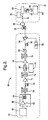
- FIG. 1 shows a Wavelength Division Multiplexing Passive Optical Network (WDM-PON) architecture according to an embodiment of the invention, generally designated 10.
- the network 10 comprises a Central Office (CO) node 12, also known as an Optical Line Termination (OLT) node, in communication with a Wavelength Division Multiplexing (WDM) distribution node 14 via a single optical fibre 16.
- CO Central Office
- OLT Optical Line Termination
- WDM Wavelength Division Multiplexing
- WDM Wavelength Division Multiplexing
- ONU Optical Network Unit
- FIG 1 has been simplified for the purposes of clarity to show one ONU 18 but it will be appreciated that in the real world example, there may be N such ONUs 18 where each ONU 1,8 serves a respective user. In this example N is typically forty. Each ONU 18 is a single user device. In Figures 1 , 2 and 5 optical connections are represented with solid lines.
- the CO node 12 comprises a Mode Locked Laser Source (MLLS) 19 capable of producing a Return-to-Zero (RZ) pulse train.
- MLLS 19 outputs to a supercontinuum generator 20 which in turn outputs to a first Array Waveguide Grating (AWG) 22 operating as a demultiplexer.
- AWG Array Waveguide Grating
- the arrangement of the MLLS 19, supercontinuum generator 20, and AWG 22 produces RZ pulsed carriers at different wavelengths on respective outputs 1 to N from the AWG 22.
- These RZ pulsed carriers are individually On-Off Key (OOK) modulated at a modulator 24 by user data. It will be appreciated that each output 1 to N has a respective modulator 24.
- OOK On-Off Key
- These 1 to N outputs are then input to a second AWG 26 operating as a multiplexer.
- the multiplexed tributary channels at different wavelengths are then passed on to an optical circulator 28 and then transmitted through the optic fibre 16 to the WDM distribution node 14.
- the tributary channels 1 to N are passively separated by means of a third AWG 30 and then sent on to respective ONUs 18 for transmission to the users.
- Figure 1 includes graphs 32 and 34 that show one modulated signal 35 in the optic fibre 16 in a downstream direction 33 output from the CO node 12.
- Graph 32 shows the downstream modulated signal 35 output from the optical circulator 28 as a data series 37 of ones and zeros 10111101, and illustrates that the downstream modulation depth for the zeros is intentionally not minimised as shown in the graph 34. This has the advantage of making the carrier recovery easier at the ONU 18 as described below.
- the downstream data is divided into two streams 29, 31 by means of an asymmetrical optical splitter 36.
- the smaller portion 29 of the signal, carrying the downstream information, is detected by an optical receiver 38 for onward transmission to a user device 59.
- the larger portion 31 of the signal is sent to a Reflective Semiconductor Optical Amplifier (RSOA) 40.
- the RSOA 40 is capable of receiving the optical data signal and partially erasing the data exploiting the device saturation properties. It will be appreciated that any optical device could be used in place of the RSOA that achieves this result. For example, an Erbium Doped Fibre Amplifier (EDFA) could be used, although it is less preferable because it requires a higher power to reach saturation.
- EDFA Erbium Doped Fibre Amplifier
- Figure 1 includes a graph 42 which shows how the data signal has been changed so that it is comprised of a data series of ones 1111111.
- the data series operates as a carrier wavelength 43 for transmission of user data in the upstream direction.
- a further graph 44 shows that the data signals above a certain minimum threshold 46 will be regarded as ones.
- the signal from the RSOA 40 is transmitted to the WDM distribution node 14, where all upstream channels from other ONUs 18 (not shown) are combined by the AWG 30 which operates as a multiplexer in the upstream direction.
- Figure 1 includes graphs 48 and 50 that show one modulated signal in the optic fibre 16 in an upstream direction 52 output from the WDM distribution node 14.
- Graph 48 shows the upstream modulation signal output from the WDM distribution node 14 with user data 49 as a series of ones and zeros 1101100.
- Graph 50 also illustrates that the upstream modulation depth for the zeros is less than the modulation depth for the downstream optical signal as shown in the graph 34. This has the advantage of allowing the zeros in the downstream and upstream direction to be more clearly distinguished from one another.
- the multiplexed signal 48 is then passed on to the CO node 12 over the optical fibre 16.
- the multiplexed signal is receive at the optical circulator 28 where it is passed on to a third AWG 54 of the CO node 12 that operates as a demultiplexer.
- Each user channel is then received by a photodetector 56 and then further transmitted in the upstream direction as required.
- FIG. 2 shows an experimental setup for the network architecture of Figure 1 , generally designated 60. Like features between Figure 1 and Figure 2 are shown with the same reference numeral.
- a RZ pulse train 10 ps wide at 2.5 Gb/s is generated by the MLLS 19 operating at 1550 nm.
- the MLLS 19 was output to the supercontinuum generator 20 which comprised of an EDFA 62 and a Highly Non-Linear Fibre (HNLF) 64 which was 250m long.
- the supercontinuum generator 20 produces a 44 nm wide supercontinuum spectrum, which is a very broadband light source generated by nonlinear processes.
- the supercontinuum generator 20 was output to a 0.8nm optical tuneable Band-Pass Filter (BPF) 66 which was used instead of the AWG 22 of Figure 1 to extract one of the carrier signals from the supercontinuum spectrum.
- BPF Band-Pass Filter
- the supercontinuum generator 20 exploits the property of production of a broadband spectra when a very high power optical signal passes through a nonlinear optical medium.
- Figure 3 shows output spectra and signal pulses at various parts of the experimental setup of Figure 2 .
- Figure 3a shows the supercontinuum spectrum from the supercontinuum generator 20.
- Figure 3b shows the RZ signal from the MLLS 19.
- Figure 3c shows the filtered RZ signal from the BPF 66.
- the downstream RZ data signal was obtained by modulating the RZ signal using a Mach-Zehnder modulator (MZ-MOD) 68.
- MZ-MOD Mach-Zehnder modulator
- the MZ-MOD 68 was driven by a Pseudo-Random Binary Sequence (PRBS) electrical signal which was 2 7 -1 in length (i.e. a binary sequence of 127 in length) generated by a Bit Pattern Generator (BPG) 70.
- PRBS Pseudo-Random Binary Sequence
- BPG Bit Pattern Generator
- An appropriate bias voltage regulation applied to the MZ-MOD 68 permits the modulation depth of the downstream signal Error Rate (ER) to be set as appropriate.
- ER Error Rate
- An Optical Delay Line (ODL) 72 and an EDFA 74 preamplifier are used before the MZ-MOD 68 in order to time-align the RZ signal with respect to the electrical data pattern from the BPG 70, and to amplify the signal to compensate for losses caused by the MZ-MOD 68.
- the optical signal was input to a further 0.8nm optical tuneable BPF 75 before being input to the MZ-MOD 68.
- the downstream RZ data signal output from the MZ-MOD 68 was then amplified by a further EDFA 76 and then filtered by a band-pass tuneable filter 78 operating at 0.8 nm-bandwidth in order to remove any out-of-band noise.
- the optical data signal was then input to a Variable Optical Attenuator (VOA) 80, and then a further ODL 82 before being passed on to the optical circulator 28.
- VOA Variable Optical Attenuator
- the obtained single tributary channel containing optical data was than launched into a 20 km-long Standard Single Mode Fiber (SMF) 16 and a 2.7 km-long Dispersion Compensating Module (DCM) 84.
- the DCM 84 operated to substantially removed the dispersion effect due to the SMF 16. In order to avoid nonlinear impairments on the transmission link, the launch power into the SMF 16 was kept below 2 dBm.
- the optical data signal was input to the asymmetrical 90/10 optical splitter 36 of the ONU 18 which permitted selection of the smaller 10% portion of the downstream signal to be sent to the downstream receiver 38.
- the 90% portion of the optical data signal was simultaneously forwarded to the RSOA 40 from the optical splitter 36.
- the downstream data was partially erased due to the RSOA 40 saturation properties to produce an optical signal comprised of ones e.g. 11111.
- the upstream modulation was subsequently applied to this optical signal.
- This upstream data signal was generated by modulating a bias current of the RSOA 40 by means of a PRBS electrical signal which was 2 7 -1 in length generated by the BPG 86 working at 2.5 Gb/s.
- a DC bias current of the RSOA 40 was fixed to 75 mA at the ONU 18 to maximize gain of the RSOA 40.
- the electrical modulation signal provided by the BPG 86 was amplified by an electrical driver 88 and coupled by means of a T-bias device 90 to the RSOA 40.
- the T-bias device 90 permits coupling a Direct Current (DC) voltage with a RF (Radio Frequency) voltage.
- This upstream optical data signal was then transmitted from the RSOA 40 through the 2.7 km-long DCM 84 and the 20km-long SMF 16. In this way the upstream and downstream optical data signals use the same optical fibre. The upstream optical data signal was then received at the circulator 28 of the CO node 12, where it was passed on to the receiver 56.
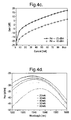
- Figure 4 shows measured characteristics of the RSOA 40 used in the experimental arrangement of Figure 2 .
- the RSOA 40 is a device available from the company CIP who supply advanced photonic components.
- the RSOA 40 had a small signal gain of 20 dB, a saturated output power of 3 dBm, a low Polarization Dependent Gain (PDG) and an ultra-low front facet reflectivity ( ⁇ 10 -5 ).
- PDG Polarization Dependent Gain
- a device characterization was performed before putting together the experimental setup of Figure 2 in order to set appropriate parameters for effective working of the RSOA 40.
- Figure 4a shows the input power against the output power at 1550 nm, 75 mA and 25°.
- Figure 4b shows the input power against gain at 1550 nm, 75 mA and 25°.
- Figure 4c illustrates the gain of the RSOA 40 as a function of the applied bias Direct Current (DC) at 1550 nm and 25°.
- Figure 4d shows the Amplified Spontaneous Emission (ASE) noise spectrum of the RSOA 40 for several bias current values.
- Figures 4a - 4d permit working parameters of the RSOA 40 to be defined so that the experimental setup 60 of Figure 2 is optimised to find a good compromise between upstream and downstream performance.
- the RSOA 40 should be operated near to the gain saturation regime.
- the input power of the RSOA 40 was kept at more than -10 dBm (shown at 58 on graph 4b) which made the device saturate when the high level signal (i.e the ones in the optical data signal) occurs. This also permits adequate low level signal (i.e. the zeros in the optical data signal) amplification.
- the optical data in the downstream optical signal is substantially or partially erased so that it is possible to write new data to the carrier wavelength whereby any remaining parts of the old optical data do not interfere with the new optical data.
- the optical data in the downstream optical signal is mostly erased, it will be appreciated that if it is not fully erased the network 10 may still function correctly to transmit user data in the upstream direction, as shown by the graph 42.
- Figure 5 shows an optical receiver for use in the experimental setup of Figure 2 , generally designated 100.
- the optical receiver 100 was used for producing the experimental results of Figures 6 - 9 .
- the optical receiver 100 was used as the ONU 18 downstream optical receiver 38 and the CO node 12 upstream optical receiver 56 of Figure 2 .
- like features to the experimental setup in Figure 2 are shown with like reference numerals.
- the optical receiver 100 allows detailed BER measurements to be carried out for the received upstream and downstream optical data signals as discussed below.
- An optical data signal input to the optical receiver 100 firstly passes through a first receiver VOA 102, and then a receiver EDFA 104, and followed by a receiver BPF 106 centred about 0.8nm to suppress out-of-band noise.
- the receiver VOA 102, the receiver EDFA 104, and the receiver BPF 106 allow the Signal-to-Noise (SN) value to be varied so that it is possible to obtain BER graphs as a function ofSN value.
- SN Signal-to-
- the optical data signal was then passed through a second receiver VOA 108 to adjust the optical power as required before being passed on to an asymmetrical splitter 109 which passed about 10% of the optical power of the optical data signal to an optical power meter 111 so that the power of the optical signal could be monitored and adjusted as required.
- the remaining 90% of the optical power of the optical data signal was passed from the asymmetrical splitter 36 to a photodetector 110 to convert the optical signal into an electrical signal which was then received by an electronic instrument 112.
- the photodetector used was a conventional 10 Gbps OOK receiver optimized for NRZ signals with a 9 GHz low-pass electrical filter.
- the photodetector 110 average input power was maintained at a constant level of -19dBm to ensure that thermal noise was negligible. Monitoring of the input power to the photodetector 110 was performed by the power meter 111.
- the electronic instrument 112 permitted the data signal to be electrically received and to perform BER measurements, and the results are presented with reference to Figures 6 - 9 .
- Figure 6 shows BER curves for the downstream and upstream signals. System performance as a function of the preamplifier average input powers were evaluated for different downstream ER values and different RSOA input power.
- Figure 6a shows results obtained with 3 dB downstream ER and an input power to the RSOA 40 from - 10 dBm to -5 dBm.
- Figure 6b shows results obtained with 4 dB downstream ER and an input power to the RSOA 40 from -10 dBm to -5 dBm.
- Figure 6c shows results obtained with 5 dB downstream ER and an input power to the RSOA 40 from -10 dBm to -5 dBm.
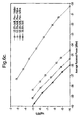
- Figure 7 shows graphs of receiver sensitivity as a function of the main transmission parameters.
- Figure 7b shows the receiver sensitivity against downstream ER for the upstream and downstream optical data signals at different input powers to the RSOA 40.
- the graphs show that as the downstream ER value increases from 3 dB to 5 dB, the upstream performance slightly deteriorates whilst the downstream performance improves more than 2.5 dBm.
- Figures 6 and 7 show that an optimal condition is reached setting the downstream ER to 5 dB and the input power to the RSOA 40 to -5 dBm because the upstream and downstream performance tends to match which makes the overall system more balanced. It was also observed that a further increase of the downstream ER over 5 dB degrades the upstream performance due to inadequate downstream modulation erasing in the RSOA 40.
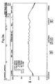
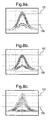
- Figure 8 shows eye diagrams at various points in the experimental setup 60 of Figure 2 for a downstream ER of 5 dB and an input power to the RSOA 40 of -5 dBm.
- a threshold level shown at 120 illustrates an optical data signal representing a zero
- a threshold level shown at 122 illustrates an optical data signal representing a one.
- Figure 8a shows the optical data signal transmitted in the downstream direction in the optical fibre 16.
- Figure 8b shows the optical data signal received by the optical receiver 38 of the ONU 18.
- Figure 8c shows the optical data signal received by the photodetector 56 of the CO node 12.
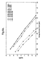
- Figure 9 shows graphs illustrating the upstream and downstream receiver sensitivity and illustrate the tolerance to residual dispersion in the optical fibre 16 of Figure 2 .
- Figure 9 shows receiver sensitivity obtained in the case of full dispersion compensation and for two different accumulated dispersion values, 40 ps/nm and 85 ps/nm, once the ER and the input power to the RSOA 40 have been fixed to optimum values of 5 dB downstream ER and -5 dBm input power to the RSOA 40.
- the graphs of Fiugre 9 show that the sensitivity degrades as the residual dispersion of the optical fibre 16 increases.
- the performance of the upstream optical data signal is shown to be worse than the downstream optical data signal which was due to the distance travelled by the upstream signal being twice the distance travelled by the downstream signal.
- Overall Figures 8 and 9 show that the link residual chromatic dispersion has a good tolerance to the RZ format.
- Figure 10 shows a flow diagram illustrating a method according to an embodiment of the invention.
- the method relates to operation of a communications network for providing communications services to at least one user.
- the method includes receiving 200 an optical signal comprising at least one Wavelength Division Multiplexing channel at a downstream direction, the channel comprising a carrier wavelength and optical data.
- the method may further include transmitting 202 the optical data to the at least one user.
- the method further includes substantially erasing 204 the data from the carrier wavelength.
- the method further includes receiving 206 user data from a downstream direction, modulating 208 the carrier wavelength with the user data, and transmitting 209 the user data in the upstream direction.
- the method includes operating 210 a RSOA 40 substantially at or close to its gain saturation regime.
- the above embodiments describe a bidirectional and dispersion tolerant 2.5 Gb/s WDM-PON based on a RZ modulation format.
- the WDM-PON can be operated in a symmetric manner such that the downstream data rate may be equal to the upstream data rate for a respective user.
- the WDM-PON uses a multi-wavelength RZ signal generator at the CO node 12, and at the RSOA 40 of the ONU 18.
- the RZ-format has the advantage of being able to provide the same bit-rate for upstream and downstream communication between the provider and the user over the same carrier wavelength. Furthermore the shorter bit time duration due to the RZ-format improves the tolerance to dispersion effects when compared to a NRZ-format.
- the RSOA 40 at the ONU 18 operates as a downstream modulation eraser, an upstream amplifier, and an upstream modulator which provides a reduction of the cost and complexity of the ONU 18 whilst avoiding the need for any additional active optical devices. Since the RSOA 40 also operates as an amplifier the power of the optical signal transmitted in the downstream direction can be reduced, hence reducing the overall link power. It will be appreciated that an advantage of the above described embodiments is that no lasers are required at the ONU 18.
- each ONU 18 is assigned a respective optical carrier frequency, but it will be appreciated that when implementing access using Time Division Multiplexing (TDM) each group of users would be assigned a respective optical carrier frequency.
- TDM Time Division Multiplexing
- a TDM demultiplexer is required before the ONU 18 to process the downstream optical signal to separate data streams for respective users.
- a TDM multiplexer is also required to combine user data into an upstream data stream.
Landscapes
- Engineering & Computer Science (AREA)
- Computer Networks & Wireless Communication (AREA)
- Signal Processing (AREA)
- Physics & Mathematics (AREA)
- Electromagnetism (AREA)
- Optical Communication System (AREA)
Claims (12)
- Vorrichtung (18), die so ausgelegt ist, dass sie ein moduliertes optisches Signal (35) empfängt, das eine Trägerwellenlänge (43) und optische Daten (37) umfasst, wobei die Vorrichtung einen optischen Verstärker umfasst, der so betrieben werden kann, dass er die Daten (37) aus dem optischen Signal (35) löscht, Benutzerdaten (49) empfängt und die Trägerwellenlänge (43) mit den Benutzerdaten (49) zur Weitersendung der Benutzerdaten (49) moduliert, dadurch gekennzeichnet, dass die Vorrichtung so ausgelegt ist, dass sie mit dem optischen Signal mit einem Rückkehr-zu-null-Modulationsformat arbeitet, und wobei der optische Verstärker (40) so ausgelegt ist, dass er in der Nähe seiner Verstärkungssättigungsschwelle (58) betrieben wird, derart dass der Verstärker zum Sättigen veranlasst wird, wenn ein höherer Pegel des optischen Signals mit dem Rückkehr-zu-null-Modulationsformat auftritt, und derart, dass der Verstärker zum Verstärken veranlasst wird, wenn ein niedriger Pegel des Rückkehr-zu-null-Modulationsformats auftritt.
- Vorrichtung (18) nach Anspruch 1, die so ausgelegt ist, dass sie das empfangene optische Signal (35) in mindestens zwei Abschnitte (29, 31) teilt (36), wobei jeder Abschnitt das modulierte optische Signal (35) umfasst.
- Vorrichtung (18) nach Anspruch 1, wobei der optische Verstärker (40) ein reflektierender optischer Halbleiterverstärker (40) ist.
- Vorrichtung (18) nach einem der vorhergehenden Ansprüche, die so ausgelegt ist, dass sie mindestens eines von dem modulierten optischen Signal (35) in einer Downstream-Richtung (33) und den Benutzerdaten (49) in einer Upstream-Richtung (52) sendet.
- Vorrichtung (18) nach einem der vorhergehenden Ansprüche und ferner so ausgelegt, dass sie das empfangene optische Signal (37) an eine Benutzereinrichtung (59) sendet.
- Verfahren zur Bereitstellung von Kommunikationsdiensten, wobei das Verfahren umfasst:Empfangen (200) eines modulierten optischen Signals (35), das eine Trägerwellenlänge (43) und optische Daten (37) umfasst; undVerwenden eines optischen Verstärkers (40) zum:Löschen (204) der Daten aus dem optischen Signal (35);Empfangen (206) von Benutzerdaten (49); undModulieren (208) der Trägerwellenlänge (43) mit den Benutzerdaten (49) zur Weitersendung der Benutzerdaten (49),dadurch gekennzeichnet, dass das Verfahren ein Empfangen des optischen Signals mit einem Rückkehr-zu-null-Modulationsformat umfasst und ferner ein Betreiben (210) des optischen Verstärkers (40) in der Nähe seiner Verstärkungssättigungsschwelle (58) umfasst, derart dass der Verstärker zum Sättigen veranlasst wird, wenn ein höherer Pegel des optischen Signals mit dem Rückkehr-zu-null-Modulationsformat auftritt, und derart, dass der Verstärker zum Verstärken veranlasst wird, wenn ein niedrigerer Pegel des Rückkehr-zu-null-Modulationsformats auftritt.
- Verfahren nach Anspruch 6 und ferner umfassend ein Teilen (36) des empfangenen optischen Signals (35) in mindestens zwei Abschnitte (29, 31), wobei jeder Abschnitt das modulierte optische Signal (35) umfasst.
- Verfahren nach Anspruch 6 oder 7 und ferner umfassend ein Senden (209) der Benutzerdaten 49) unter Verwendung des optischen Verstärkers (40).
- Verfahren nach Anspruch 8 und ferner umfassend ein Verwenden eines reflektierenden optischen Halbleiterverstärkers (40) als den optischen Verstärker.
- Verfahren nach einem der Ansprüche 6 bis 9, umfassend ein Senden mindestens eines von dem modulierten optischen Signal (35) in einer Downstream-Richtung (33) und den Benutzerdaten (49) in einer Upstream-Richtung (52).
- Verfahren nach einem der Ansprüche 6 bis 10 und ferner umfassend ein Senden (202) der empfangenen optischen Daten (37) an eine Benutzereinrichtung (59).
- Kommunikationsnetz, umfassend eine Vorrichtung nach einem der Ansprüche 1 bis 5 oder ausgelegt zum Durchführen eines Verfahrens nach einem der Ansprüche 6 bis 11.
Applications Claiming Priority (1)
| Application Number | Priority Date | Filing Date | Title |
|---|---|---|---|
| PCT/EP2008/054265 WO2009124588A1 (en) | 2008-04-09 | 2008-04-09 | Improvements in or relating to optical networks |
Publications (2)
| Publication Number | Publication Date |
|---|---|
| EP2260596A1 EP2260596A1 (de) | 2010-12-15 |
| EP2260596B1 true EP2260596B1 (de) | 2013-03-13 |
Family
ID=40076876
Family Applications (1)
| Application Number | Title | Priority Date | Filing Date |
|---|---|---|---|
| EP08735991A Not-in-force EP2260596B1 (de) | 2008-04-09 | 2008-04-09 | Verbesserungen in bezug auf optische netzwerke |
Country Status (3)
| Country | Link |
|---|---|
| US (1) | US20110110671A1 (de) |
| EP (1) | EP2260596B1 (de) |
| WO (1) | WO2009124588A1 (de) |
Families Citing this family (3)
| Publication number | Priority date | Publication date | Assignee | Title |
|---|---|---|---|---|
| US8478134B2 (en) * | 2009-08-31 | 2013-07-02 | Ofs Fitel, Llc | Compression of generated optical continuum utilizing higher-order-mode fiber |
| GB0919029D0 (en) * | 2009-10-30 | 2009-12-16 | Univ Bangor | Use of the same set of wavelengths for uplink and downlink signal transmission |
| US8909050B2 (en) * | 2010-04-30 | 2014-12-09 | Telefonaktiebolaget L M Ericsson (Publ) | Passive optical networks |
Family Cites Families (10)
| Publication number | Priority date | Publication date | Assignee | Title |
|---|---|---|---|---|
| CA2118616C (en) * | 1993-03-11 | 1999-09-14 | Thomas Edward Darcie | Optical network based on remote interrogation of terminal equipment |
| US5815295A (en) * | 1993-03-11 | 1998-09-29 | Lucent Technologies Inc. | Optical communication system with improved maintenance capabilities |
| JPH09214440A (ja) * | 1996-02-05 | 1997-08-15 | Kokusai Denshin Denwa Co Ltd <Kdd> | パルス情報の双方向伝送方式及び光送受信装置 |
| US6961521B1 (en) * | 2001-03-27 | 2005-11-01 | Turin Networks | Method and apparatus for transmitting a bit interleaved optical data stream on an optical network |
| KR100575953B1 (ko) * | 2003-10-27 | 2006-05-02 | 삼성전자주식회사 | 반사형 이득고정 반도체 광증폭기를 포함하는 광신호전송장치 및 이를 이용한 광통신 시스템 |
| KR100675834B1 (ko) * | 2004-10-28 | 2007-01-29 | 한국전자통신연구원 | 루프백 형 파장분할다중방식의 수동형 광 네트워크 |
| US20070147837A1 (en) * | 2005-12-07 | 2007-06-28 | Yoo Jeong J | Method of increasing number of subscribers using time division duplexing technology in wavelength division multiplexing/Ethernet passive optical network system |
| KR100819034B1 (ko) * | 2006-05-11 | 2008-04-03 | 한국전자통신연구원 | 반사형 반도체 광증폭기 기반 수동형 광가입자망 |
| US20080131125A1 (en) * | 2006-12-01 | 2008-06-05 | Kim Byoung Whi | Loopback-type wavelength division multiplexing passive optical network system |
| KR100870897B1 (ko) * | 2007-02-06 | 2008-11-28 | 한국과학기술원 | 전송품질이 개선된 반사형 반도체 광증폭기 기반광가입자망 시스템 |
-
2008
- 2008-04-09 WO PCT/EP2008/054265 patent/WO2009124588A1/en not_active Ceased
- 2008-04-09 US US12/936,209 patent/US20110110671A1/en not_active Abandoned
- 2008-04-09 EP EP08735991A patent/EP2260596B1/de not_active Not-in-force
Also Published As
| Publication number | Publication date |
|---|---|
| US20110110671A1 (en) | 2011-05-12 |
| WO2009124588A1 (en) | 2009-10-15 |
| EP2260596A1 (de) | 2010-12-15 |
Similar Documents
| Publication | Publication Date | Title |
|---|---|---|
| EP2332276B1 (de) | Passive optische netzwerke | |
| US9002204B2 (en) | 1 Tb/s converged optical metro-access transmission based on wavelength division multiplexed orthogonal frequency division multiple access passive optical network (WDM-OFDMA-PON) | |
| CN113169799B (zh) | 具有增强灵活性的光线路终端和光纤接入系统 | |
| CN111344968B (zh) | 光线路终端和容量增加的光纤接入系统 | |
| WO2008014374A2 (en) | Controlling optical signal transmission to reduce optical signal degradation | |
| Matsumoto et al. | Burst-mode coherent detection using fast-fitting pilot sequence for 100-Gb/sM coherent TDM-PON system | |
| Bi et al. | Power budget improved symmetric 40-Gb/s long reach stacked WDM-OFDM-PON system based on single tunable optical filter | |
| US20100239258A1 (en) | Optical pon network using passive dpsk demodulation | |
| US8285147B2 (en) | Bulk modulation of multiple wavelengths for generation of CATV optical comb | |
| Mandal et al. | High capacity hybrid WDM/TDM-PON employing fiber-to-the-home for triple-play services with 128 ONUs | |
| Yeh et al. | Using OOK modulation for symmetric 40-Gb/s long-reach time-sharing passive optical networks | |
| US20120224854A1 (en) | Use of the same set of wavelengths for uplink and downlink signal transmission | |
| Chow et al. | Rayleigh backscattering mitigation using wavelength splitting for heterogeneous optical wired and wireless access | |
| EP2260596B1 (de) | Verbesserungen in bezug auf optische netzwerke | |
| Aly et al. | Evaluation and optimization of TWDM-PON system capacity over single bidirectional optical fiber: Migration promising solution for the next generation PONs | |
| Berrettini et al. | Colorless WDM-PON architecture for Rayleigh backscattering and path-loss degradation mitigation | |
| Straullu et al. | Self-coherent reflective passive optical networks | |
| Kurbatska et al. | Comparison of modulation formats for use in the next generation passive optical networks | |
| WO2007091013A1 (en) | Optical communication | |
| El-Sahn et al. | Bidirectional WDM PON enabled by reflective ONUs and a novel overlapped-subcarrier multiplexing technique | |
| Bonk et al. | Real-time demonstration of 28 Gbit/s electrical duobinary TDM-PON extension using remote nodes | |
| Fresi et al. | Single RSOA based ONU for RZ symmetrical WDM PONs at 2.5 Gb/s | |
| Chow et al. | Long-reach WDM PONs | |
| Chiuchiarelli et al. | Coherent Optical Access Networks | |
| Nadarajah et al. | Upstream Transmission and Local Area Network Emulation in Passive Optical Networks Using a Single Wavelength-seeded RSOA |
Legal Events
| Date | Code | Title | Description |
|---|---|---|---|
| PUAI | Public reference made under article 153(3) epc to a published international application that has entered the european phase |
Free format text: ORIGINAL CODE: 0009012 |
|
| 17P | Request for examination filed |
Effective date: 20100908 |
|
| AK | Designated contracting states |
Kind code of ref document: A1 Designated state(s): AT BE BG CH CY CZ DE DK EE ES FI FR GB GR HR HU IE IS IT LI LT LU LV MC MT NL NO PL PT RO SE SI SK TR |
|
| AX | Request for extension of the european patent |
Extension state: AL BA MK RS |
|
| DAX | Request for extension of the european patent (deleted) | ||
| GRAP | Despatch of communication of intention to grant a patent |
Free format text: ORIGINAL CODE: EPIDOSNIGR1 |
|
| GRAS | Grant fee paid |
Free format text: ORIGINAL CODE: EPIDOSNIGR3 |
|
| REG | Reference to a national code |
Ref country code: DE Ref legal event code: R079 Ref document number: 602008022879 Country of ref document: DE Free format text: PREVIOUS MAIN CLASS: H04B0010260000 Ipc: H04B0010258700 |
|
| GRAA | (expected) grant |
Free format text: ORIGINAL CODE: 0009210 |
|
| AK | Designated contracting states |
Kind code of ref document: B1 Designated state(s): AT BE BG CH CY CZ DE DK EE ES FI FR GB GR HR HU IE IS IT LI LT LU LV MC MT NL NO PL PT RO SE SI SK TR |
|
| REG | Reference to a national code |
Ref country code: GB Ref legal event code: FG4D |
|
| RIC1 | Information provided on ipc code assigned before grant |
Ipc: H04B 10/2587 20130101AFI20130204BHEP |
|
| REG | Reference to a national code |
Ref country code: AT Ref legal event code: REF Ref document number: 601323 Country of ref document: AT Kind code of ref document: T Effective date: 20130315 Ref country code: CH Ref legal event code: EP |
|
| REG | Reference to a national code |
Ref country code: IE Ref legal event code: FG4D |
|
| REG | Reference to a national code |
Ref country code: DE Ref legal event code: R096 Ref document number: 602008022879 Country of ref document: DE Effective date: 20130508 |
|
| REG | Reference to a national code |
Ref country code: NL Ref legal event code: T3 |
|
| PG25 | Lapsed in a contracting state [announced via postgrant information from national office to epo] |
Ref country code: BG Free format text: LAPSE BECAUSE OF FAILURE TO SUBMIT A TRANSLATION OF THE DESCRIPTION OR TO PAY THE FEE WITHIN THE PRESCRIBED TIME-LIMIT Effective date: 20130613 Ref country code: SE Free format text: LAPSE BECAUSE OF FAILURE TO SUBMIT A TRANSLATION OF THE DESCRIPTION OR TO PAY THE FEE WITHIN THE PRESCRIBED TIME-LIMIT Effective date: 20130313 Ref country code: NO Free format text: LAPSE BECAUSE OF FAILURE TO SUBMIT A TRANSLATION OF THE DESCRIPTION OR TO PAY THE FEE WITHIN THE PRESCRIBED TIME-LIMIT Effective date: 20130613 Ref country code: ES Free format text: LAPSE BECAUSE OF FAILURE TO SUBMIT A TRANSLATION OF THE DESCRIPTION OR TO PAY THE FEE WITHIN THE PRESCRIBED TIME-LIMIT Effective date: 20130624 Ref country code: LT Free format text: LAPSE BECAUSE OF FAILURE TO SUBMIT A TRANSLATION OF THE DESCRIPTION OR TO PAY THE FEE WITHIN THE PRESCRIBED TIME-LIMIT Effective date: 20130313 |
|
| REG | Reference to a national code |
Ref country code: AT Ref legal event code: MK05 Ref document number: 601323 Country of ref document: AT Kind code of ref document: T Effective date: 20130313 |
|
| REG | Reference to a national code |
Ref country code: LT Ref legal event code: MG4D |
|
| PG25 | Lapsed in a contracting state [announced via postgrant information from national office to epo] |
Ref country code: LV Free format text: LAPSE BECAUSE OF FAILURE TO SUBMIT A TRANSLATION OF THE DESCRIPTION OR TO PAY THE FEE WITHIN THE PRESCRIBED TIME-LIMIT Effective date: 20130313 Ref country code: FI Free format text: LAPSE BECAUSE OF FAILURE TO SUBMIT A TRANSLATION OF THE DESCRIPTION OR TO PAY THE FEE WITHIN THE PRESCRIBED TIME-LIMIT Effective date: 20130313 Ref country code: GR Free format text: LAPSE BECAUSE OF FAILURE TO SUBMIT A TRANSLATION OF THE DESCRIPTION OR TO PAY THE FEE WITHIN THE PRESCRIBED TIME-LIMIT Effective date: 20130614 Ref country code: SI Free format text: LAPSE BECAUSE OF FAILURE TO SUBMIT A TRANSLATION OF THE DESCRIPTION OR TO PAY THE FEE WITHIN THE PRESCRIBED TIME-LIMIT Effective date: 20130313 |
|
| PG25 | Lapsed in a contracting state [announced via postgrant information from national office to epo] |
Ref country code: BE Free format text: LAPSE BECAUSE OF FAILURE TO SUBMIT A TRANSLATION OF THE DESCRIPTION OR TO PAY THE FEE WITHIN THE PRESCRIBED TIME-LIMIT Effective date: 20130313 Ref country code: HR Free format text: LAPSE BECAUSE OF FAILURE TO SUBMIT A TRANSLATION OF THE DESCRIPTION OR TO PAY THE FEE WITHIN THE PRESCRIBED TIME-LIMIT Effective date: 20130313 |
|
| PG25 | Lapsed in a contracting state [announced via postgrant information from national office to epo] |
Ref country code: IS Free format text: LAPSE BECAUSE OF FAILURE TO SUBMIT A TRANSLATION OF THE DESCRIPTION OR TO PAY THE FEE WITHIN THE PRESCRIBED TIME-LIMIT Effective date: 20130713 Ref country code: RO Free format text: LAPSE BECAUSE OF FAILURE TO SUBMIT A TRANSLATION OF THE DESCRIPTION OR TO PAY THE FEE WITHIN THE PRESCRIBED TIME-LIMIT Effective date: 20130313 Ref country code: EE Free format text: LAPSE BECAUSE OF FAILURE TO SUBMIT A TRANSLATION OF THE DESCRIPTION OR TO PAY THE FEE WITHIN THE PRESCRIBED TIME-LIMIT Effective date: 20130313 Ref country code: SK Free format text: LAPSE BECAUSE OF FAILURE TO SUBMIT A TRANSLATION OF THE DESCRIPTION OR TO PAY THE FEE WITHIN THE PRESCRIBED TIME-LIMIT Effective date: 20130313 Ref country code: PT Free format text: LAPSE BECAUSE OF FAILURE TO SUBMIT A TRANSLATION OF THE DESCRIPTION OR TO PAY THE FEE WITHIN THE PRESCRIBED TIME-LIMIT Effective date: 20130715 Ref country code: AT Free format text: LAPSE BECAUSE OF FAILURE TO SUBMIT A TRANSLATION OF THE DESCRIPTION OR TO PAY THE FEE WITHIN THE PRESCRIBED TIME-LIMIT Effective date: 20130313 Ref country code: CZ Free format text: LAPSE BECAUSE OF FAILURE TO SUBMIT A TRANSLATION OF THE DESCRIPTION OR TO PAY THE FEE WITHIN THE PRESCRIBED TIME-LIMIT Effective date: 20130313 |
|
| PG25 | Lapsed in a contracting state [announced via postgrant information from national office to epo] |
Ref country code: PL Free format text: LAPSE BECAUSE OF FAILURE TO SUBMIT A TRANSLATION OF THE DESCRIPTION OR TO PAY THE FEE WITHIN THE PRESCRIBED TIME-LIMIT Effective date: 20130313 Ref country code: CY Free format text: LAPSE BECAUSE OF FAILURE TO SUBMIT A TRANSLATION OF THE DESCRIPTION OR TO PAY THE FEE WITHIN THE PRESCRIBED TIME-LIMIT Effective date: 20130313 |
|
| REG | Reference to a national code |
Ref country code: CH Ref legal event code: PL |
|
| PG25 | Lapsed in a contracting state [announced via postgrant information from national office to epo] |
Ref country code: MC Free format text: LAPSE BECAUSE OF FAILURE TO SUBMIT A TRANSLATION OF THE DESCRIPTION OR TO PAY THE FEE WITHIN THE PRESCRIBED TIME-LIMIT Effective date: 20130313 |
|
| PLBE | No opposition filed within time limit |
Free format text: ORIGINAL CODE: 0009261 |
|
| STAA | Information on the status of an ep patent application or granted ep patent |
Free format text: STATUS: NO OPPOSITION FILED WITHIN TIME LIMIT |
|
| REG | Reference to a national code |
Ref country code: IE Ref legal event code: MM4A |
|
| PG25 | Lapsed in a contracting state [announced via postgrant information from national office to epo] |
Ref country code: LI Free format text: LAPSE BECAUSE OF NON-PAYMENT OF DUE FEES Effective date: 20130430 Ref country code: DK Free format text: LAPSE BECAUSE OF FAILURE TO SUBMIT A TRANSLATION OF THE DESCRIPTION OR TO PAY THE FEE WITHIN THE PRESCRIBED TIME-LIMIT Effective date: 20130313 Ref country code: CH Free format text: LAPSE BECAUSE OF NON-PAYMENT OF DUE FEES Effective date: 20130430 |
|
| REG | Reference to a national code |
Ref country code: FR Ref legal event code: ST Effective date: 20131231 |
|
| 26N | No opposition filed |
Effective date: 20131216 |
|
| PG25 | Lapsed in a contracting state [announced via postgrant information from national office to epo] |
Ref country code: FR Free format text: LAPSE BECAUSE OF NON-PAYMENT OF DUE FEES Effective date: 20130513 Ref country code: IT Free format text: LAPSE BECAUSE OF FAILURE TO SUBMIT A TRANSLATION OF THE DESCRIPTION OR TO PAY THE FEE WITHIN THE PRESCRIBED TIME-LIMIT Effective date: 20130313 |
|
| REG | Reference to a national code |
Ref country code: DE Ref legal event code: R097 Ref document number: 602008022879 Country of ref document: DE Effective date: 20131216 |
|
| PG25 | Lapsed in a contracting state [announced via postgrant information from national office to epo] |
Ref country code: IE Free format text: LAPSE BECAUSE OF NON-PAYMENT OF DUE FEES Effective date: 20130409 |
|
| PG25 | Lapsed in a contracting state [announced via postgrant information from national office to epo] |
Ref country code: MT Free format text: LAPSE BECAUSE OF FAILURE TO SUBMIT A TRANSLATION OF THE DESCRIPTION OR TO PAY THE FEE WITHIN THE PRESCRIBED TIME-LIMIT Effective date: 20130313 |
|
| PG25 | Lapsed in a contracting state [announced via postgrant information from national office to epo] |
Ref country code: TR Free format text: LAPSE BECAUSE OF FAILURE TO SUBMIT A TRANSLATION OF THE DESCRIPTION OR TO PAY THE FEE WITHIN THE PRESCRIBED TIME-LIMIT Effective date: 20130313 |
|
| PGFP | Annual fee paid to national office [announced via postgrant information from national office to epo] |
Ref country code: NL Payment date: 20150426 Year of fee payment: 8 |
|
| PG25 | Lapsed in a contracting state [announced via postgrant information from national office to epo] |
Ref country code: LU Free format text: LAPSE BECAUSE OF NON-PAYMENT OF DUE FEES Effective date: 20130409 Ref country code: HU Free format text: LAPSE BECAUSE OF FAILURE TO SUBMIT A TRANSLATION OF THE DESCRIPTION OR TO PAY THE FEE WITHIN THE PRESCRIBED TIME-LIMIT; INVALID AB INITIO Effective date: 20080409 |
|
| PGFP | Annual fee paid to national office [announced via postgrant information from national office to epo] |
Ref country code: DE Payment date: 20150429 Year of fee payment: 8 Ref country code: GB Payment date: 20150427 Year of fee payment: 8 |
|
| REG | Reference to a national code |
Ref country code: DE Ref legal event code: R119 Ref document number: 602008022879 Country of ref document: DE |
|
| REG | Reference to a national code |
Ref country code: NL Ref legal event code: MM Effective date: 20160501 |
|
| GBPC | Gb: european patent ceased through non-payment of renewal fee |
Effective date: 20160409 |
|
| PG25 | Lapsed in a contracting state [announced via postgrant information from national office to epo] |
Ref country code: NL Free format text: LAPSE BECAUSE OF NON-PAYMENT OF DUE FEES Effective date: 20160501 Ref country code: DE Free format text: LAPSE BECAUSE OF NON-PAYMENT OF DUE FEES Effective date: 20161101 Ref country code: GB Free format text: LAPSE BECAUSE OF NON-PAYMENT OF DUE FEES Effective date: 20160409 |