EP2260501B1 - Xrf system having multiple excitation energy bands in highly aligned package - Google Patents
Xrf system having multiple excitation energy bands in highly aligned package Download PDFInfo
- Publication number
- EP2260501B1 EP2260501B1 EP09716373.7A EP09716373A EP2260501B1 EP 2260501 B1 EP2260501 B1 EP 2260501B1 EP 09716373 A EP09716373 A EP 09716373A EP 2260501 B1 EP2260501 B1 EP 2260501B1
- Authority
- EP
- European Patent Office
- Prior art keywords
- ray
- optics
- housing section
- optic
- spot
- Prior art date
- Legal status (The legal status is an assumption and is not a legal conclusion. Google has not performed a legal analysis and makes no representation as to the accuracy of the status listed.)
- Active
Links
Images




Classifications
-
- G—PHYSICS
- G21—NUCLEAR PHYSICS; NUCLEAR ENGINEERING
- G21K—HANDLING OF PARTICLES OR IONISING RADIATION NOT OTHERWISE PROVIDED FOR; IRRADIATION DEVICES; GAMMA RAY OR X-RAY MICROSCOPES
- G21K1/00—Arrangements for handling particles or ionising radiation, e.g. focusing or moderating
- G21K1/06—Arrangements for handling particles or ionising radiation, e.g. focusing or moderating using diffraction, refraction or reflection, e.g. monochromators
-
- G—PHYSICS
- G01—MEASURING; TESTING
- G01N—INVESTIGATING OR ANALYSING MATERIALS BY DETERMINING THEIR CHEMICAL OR PHYSICAL PROPERTIES
- G01N23/00—Investigating or analysing materials by the use of wave or particle radiation, e.g. X-rays or neutrons, not covered by groups G01N3/00 – G01N17/00, G01N21/00 or G01N22/00
- G01N23/22—Investigating or analysing materials by the use of wave or particle radiation, e.g. X-rays or neutrons, not covered by groups G01N3/00 – G01N17/00, G01N21/00 or G01N22/00 by measuring secondary emission from the material
- G01N23/223—Investigating or analysing materials by the use of wave or particle radiation, e.g. X-rays or neutrons, not covered by groups G01N3/00 – G01N17/00, G01N21/00 or G01N22/00 by measuring secondary emission from the material by irradiating the sample with X-rays or gamma-rays and by measuring X-ray fluorescence
-
- G—PHYSICS
- G01—MEASURING; TESTING
- G01N—INVESTIGATING OR ANALYSING MATERIALS BY DETERMINING THEIR CHEMICAL OR PHYSICAL PROPERTIES
- G01N23/00—Investigating or analysing materials by the use of wave or particle radiation, e.g. X-rays or neutrons, not covered by groups G01N3/00 – G01N17/00, G01N21/00 or G01N22/00
- G01N23/20—Investigating or analysing materials by the use of wave or particle radiation, e.g. X-rays or neutrons, not covered by groups G01N3/00 – G01N17/00, G01N21/00 or G01N22/00 by using diffraction of the radiation by the materials, e.g. for investigating crystal structure; by using scattering of the radiation by the materials, e.g. for investigating non-crystalline materials; by using reflection of the radiation by the materials
- G01N23/20008—Constructional details of analysers, e.g. characterised by X-ray source, detector or optical system; Accessories therefor; Preparing specimens therefor
-
- H—ELECTRICITY
- H05—ELECTRIC TECHNIQUES NOT OTHERWISE PROVIDED FOR
- H05G—X-RAY TECHNIQUE
- H05G1/00—X-ray apparatus involving X-ray tubes; Circuits therefor
- H05G1/02—Constructional details
- H05G1/04—Mounting the X-ray tube within a closed housing
-
- G—PHYSICS
- G01—MEASURING; TESTING
- G01N—INVESTIGATING OR ANALYSING MATERIALS BY DETERMINING THEIR CHEMICAL OR PHYSICAL PROPERTIES
- G01N2223/00—Investigating materials by wave or particle radiation
- G01N2223/07—Investigating materials by wave or particle radiation secondary emission
- G01N2223/076—X-ray fluorescence
-
- G—PHYSICS
- G01—MEASURING; TESTING
- G01N—INVESTIGATING OR ANALYSING MATERIALS BY DETERMINING THEIR CHEMICAL OR PHYSICAL PROPERTIES
- G01N2223/00—Investigating materials by wave or particle radiation
- G01N2223/10—Different kinds of radiation or particles
- G01N2223/1003—Different kinds of radiation or particles monochromatic
-
- G—PHYSICS
- G01—MEASURING; TESTING
- G01N—INVESTIGATING OR ANALYSING MATERIALS BY DETERMINING THEIR CHEMICAL OR PHYSICAL PROPERTIES
- G01N2223/00—Investigating materials by wave or particle radiation
- G01N2223/30—Accessories, mechanical or electrical features
- G01N2223/315—Accessories, mechanical or electrical features monochromators
-
- G—PHYSICS
- G01—MEASURING; TESTING
- G01N—INVESTIGATING OR ANALYSING MATERIALS BY DETERMINING THEIR CHEMICAL OR PHYSICAL PROPERTIES
- G01N2223/00—Investigating materials by wave or particle radiation
- G01N2223/40—Imaging
- G01N2223/423—Imaging multispectral imaging-multiple energy imaging
-
- G—PHYSICS
- G21—NUCLEAR PHYSICS; NUCLEAR ENGINEERING
- G21K—HANDLING OF PARTICLES OR IONISING RADIATION NOT OTHERWISE PROVIDED FOR; IRRADIATION DEVICES; GAMMA RAY OR X-RAY MICROSCOPES
- G21K2201/00—Arrangements for handling radiation or particles
- G21K2201/06—Arrangements for handling radiation or particles using diffractive, refractive or reflecting elements
- G21K2201/062—Arrangements for handling radiation or particles using diffractive, refractive or reflecting elements the element being a crystal
-
- G—PHYSICS
- G21—NUCLEAR PHYSICS; NUCLEAR ENGINEERING
- G21K—HANDLING OF PARTICLES OR IONISING RADIATION NOT OTHERWISE PROVIDED FOR; IRRADIATION DEVICES; GAMMA RAY OR X-RAY MICROSCOPES
- G21K2201/00—Arrangements for handling radiation or particles
- G21K2201/06—Arrangements for handling radiation or particles using diffractive, refractive or reflecting elements
- G21K2201/064—Arrangements for handling radiation or particles using diffractive, refractive or reflecting elements having a curved surface
Definitions
- the present invention relates generally to x-ray analysis systems, and more particularly, to x-ray source assemblies providing multiple excitation energies to improve detection and analysis of multiple elements in homogeneous and heterogeneous sample structures.
- the present invention provides a measurement solution having fast, accurate results for toxins in manufactured products, enabled by sophisticated proprietary x-ray optics.
- Such proprietary optics typically provide 10 - 1,000x improvements in the ability to focus x-rays; and optic-enabled analyzers are especially suited for these targeted markets - moving measurements from the lab into the factory, field, and clinic.
- x-ray analysis systems In x-ray analysis systems, high x-ray beam intensity and small beam spot sizes are important to reduce sample exposure times, increase spatial resolution, and consequently, improve the signal-to-background ratio and overall quality of x-ray analysis measurements.
- expensive and powerful x-ray sources such as rotating anode x-ray tubes or synchrotrons, were the only options available to produce high-intensity x-ray beams, in the laboratory.
- x-ray optic devices has made it possible to collect the diverging radiation from an x-ray source by focusing the x-rays.
- a combination of x-ray focusing optics and small, low-power x-ray sources can produce x-ray beams with intensities comparable to those achieved with more expensive devices.
- Monochromatization of x-ray beams in the excitation and/or detection paths is also useful to excite and/or detect very precise portions of the x-ray energy spectrum corresponding to various elements of interest (lead, etc.).
- X-ray monochromatization technology is based on diffraction of x-rays on optical crystals, for example, germanium (Ge) or silicon (Si) crystals. Curved crystals can provide deflection of diverging radiation from an x-ray source onto a target, as well as providing monochromatization of photons reaching the target.
- Two common types of curved crystals are known as singly-curved crystals and doubly-curved crystals (DCCs).
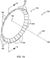
- Fig. 1a is a representative isometric view of this x-ray optic arrangement 150 having a curved optic 152, an x-ray source location 154, and an x-ray target location 156.
- X-ray source location 154 and x-ray target location 156 define a source-to-target transmission axis 162.
- Optic 152 may include a plurality of individual optic crystals 164, all of which may be arranged symmetrically about axis 162.
- Fig. 1b is a cross-sectional view taken along section lines 1b--1b of Fig. 1a , wherein the surface of optic 152, x-ray source location 154, and x-ray target location 156 define one or more Rowland (or focal) circles 160 and 161 of radius R for optic 152.
- Rowland circles 160 and 161 of radius R for optic 152.
- Those skilled in the art will recognize that the number and orientation of the Rowland circles associated with crystal optic 152, or individual crystals 164, will vary with the position of the surface of optic crystal 152, for example, the variation of the toroidal position on optic crystal 152.
- the internal atomic diffraction planes of optic crystal 152 also may not be parallel to its surface.
- the atomic diffraction planes of crystal 152 make an angle ⁇ 1 with the surface upon which x-rays are directed, at the point of tangency 158 of the surface and its corresponding optic circle 160 or 161.
- ⁇ B is the Bragg angle for crystal optic 152 which determines its diffractive effect.
- Each individual optic crystal can in one example be fabricated according to the method disclosed in above-mentioned U.S. Pat. No. 6,285,506 , entitled "Curved Optical Device and Method of Fabrication.”
- All individual crystals 164 should be aligned to the source-to-target axis 162, for proper Bragg conditions. Improvement in optic alignment, especially for such multiple-crystal optics, therefore remains an important area of interest. Another issue, which particularly affects volume manufacturing, is the need to align disparate components which may be purchased from different vendors. For example, the x-ray tubes, when purchased in quantities from a vendor, may have source x-ray spots which are not consistently centered relative to their own housings. Re-centering these x-ray tube spots is necessary, as an initial step in the alignment process for an entire x-ray source assembly.
- Patents Nos. 7,110,506 ; 7,209,545 ; and 7,257,193 address certain tube/optic alignment problems during source operation with real-time, corrective feedback approaches for alignment between the tube focal spot, optic, and output focal spot. Sensors are used to detect various operating conditions, and mechanical and/or thermal adjustments are made to correct for instabilities, including misalignments. These types of systems are necessary and valuable for certain applications, but can also increase the cost and complexity of fielded systems.
- Improved x-ray analysis method and systems are required, therefore, to address the problems associated with measuring multiple toxins in potentially heterogeneous samples, to enable in-the-factory and/or in-the-field measurement of toxins in manufactured products.
- JP2002195963 discloses an X-ray spectroscope/analysing apparatus and makes reference i.a. to JPH1123797 which discloses a spectroscope of cylindrical crystal type and the manufacture thereof.
- US5132997 discloses an X-ray spectroscopic analyzing apparatus and US6023496 discloses an X-ray fluorescence analyzing apparatus.
- JP2001194325 discloses an X-ray analyzer which has an optical system with a total reflection collimator for radiating short wavelength X-ray to a sample.
- the first x-ray optic may monochromate characteristic energy from the source spot
- the second x-ray optic may monochromate bremsstrahlung energy from the source spot.
- the x-ray optics are curved diffracting optics, for receiving the diverging x-ray beam from the x-ray tube and focusing the beam at the sample spot. Detection is also provided to detect and measure various toxins in, e.g., manufactured products including toys and electronics.
- Optic-enabled, monochromatic-excited, micro-focus energy-dispersive XRF utilizes the above-discussed advanced x-ray optics together with a low-wattage x-ray tube, commercially available sensors, and proprietary software algorithms in a compact touch-and-shoot design.
- the optics greatly improve the signal-to-noise and concentrate the intensity in a small spot.
- the optic-enabled analyzer can nondestructively detect and quantify multiple toxic elements simultaneously in the small features typically found in products such as toys and electronics, regardless of the product's shape, size, or homogeneity. Its simple-to-use design enables the quantifiable measurement of toxin concentrations as low as 1 ppm.
- the system maintains secure records including clear time-stamped photographic identification of the toy and feature measured, ensuring auditable compliance.
- Doubly Curved Crystal (DCC) monochromating optics can be used to enhance measurement intensities by capturing x-rays from a divergent source and redirecting them into an intense focused beam on the surface of the product.
- Their small spot size allows the analyzer to inspect small features down to 1.5mm in diameter with no reduction in speed or data quality. This unique capability will distinguish very small features commonly seen in toys and electronics. Regulations require that each material be evaluated separately; the limits are per material and color, not averaging across multiple features.
- the favorable signal-to-noise ratio enabled by the optics provides the analyzer with extremely low limits of detection. This high-performance limit-of-detection increases the reliability of results, hence dramatically reducing the number of false positives or negatives. The analyzer will remain effective even at lowest proposed regulatory limits of 40ppm for lead.
- Paint coatings are of particular interest in the toy market so the toy analyzer has incorporated a dedicated coating optic with optimum energy levels and angles to isolate paint layers.
- Conventional XRF technologies without optics take an average of the coating and substrate layers that can mask high toxin levels in the paint layer.
- the toy analyzer can distinguish the composition of the paint coating layer from the substrate.
- the multi-element capability can simultaneously provide results on the most requested toxins in toys and other consumer products. At least 26 different elements can be detected simultaneously using the system, with emphasis on the 10 toxins of greatest interest to manufacturers including Cr, As, Br, Cd, Sb, Ba, Se, Hg, Cl & Pb.
- Figs 2-4 depict in various views (using like numerals to refer to like elements) a highly-aligned x-ray optic and source assembly 200 in accordance with the present invention.
- the assembly includes a first section 210, second section 220, and third section 230, which together align an x-ray tube 240 to a sample spot 250, along a central transmission axis Z. Also aligned along this axis are multiple optic carriage assemblies 222, 224, and 226 which hold exemplary monochromating optics also requiring alignment to transmission axis Z (as discussed above with respect to Figs. la-b).
- First housing section 210 includes adjustable tube-mounting features 212, 214 about its perimeter for adjustably mounting tube 240 thereby ensuring centering of tube x-ray spot 242 centrally along a central axis of section 210 (not shown).
- adjustable tube-mounting features 212, 214 about its perimeter for adjustably mounting tube 240 thereby ensuring centering of tube x-ray spot 242 centrally along a central axis of section 210 (not shown).
- further attachment of assembly sections 210, 220, and 230 will ensure that each respective section's axis (not shown) is ultimately aligned to the transmission axis Z. Therefore, the present invention allows for incremental alignment of potentially disparate components along the central transmission axis Z.
- x-ray tube 240 they may be shipped with slightly off-center tube spots from the manufacturer, and therefore are required to be re-centered along section 210's axis using adjustable mounting features 212 and 214 (e.g., set screws).
- x-ray tube and optic technology The ability to provide an efficient, economical, portable analysis capability depends to a large extent upon x-ray tube and optic technology.
- certain tube and optic technology can be combined for smaller, portable systems, e.g., a compact, electron-bombardment x-ray tube.
- x-ray tube is available from Oxford Instruments - model # 5011, which operates at less than 100 watts (i.e., 75 watts) at a cost of less than $1500 per tube, in contrast to higher-power, laboratory sources which can cost many thousands, or hundreds of thousands of dollars - which is cost prohibitive for many applications.
- Varian VF-50J similar to that depicted here
- tubular in shape and which operates at 50 watts or less, at a cost of several thousand dollars each, with a molybdenum material, as discussed further below.
- Second housing section 220 includes additional alignment features.
- First, complimentary mating surfaces 216 and 228 ( Fig. 4 ) are provided to align the axes of sections 210 and 220 upon assembly, i.e., upon insertion of tube section 210 into section 220.
- Sections 210 and 220 are separately fabricated to guarantee alignment along their axes, and therefore to the central axis Z, when the mating surfaces are in contact.
- Sections 210, 220, and 230 are of tubular shape. Specifically, the sections are shown in the approximate form of a cylinder, with a circular cross-section, which is one type of tubular shape. The cross-section of tubular sections 210 and 220 could also be square, rectangular, etc. The tubular shapes shown, with circular cross-sections, provide a section-section alignment technique using outer perimeter mating surface 216 of section 210 and inner perimeter mating surface 218 of section 220. The fully enclosed tubular sections also provide required x-ray shielding.
- section 220 also accommodates the attachment of optic carriages 222, 224, and 226, which are fabricated to adjustably mount and align x-ray optics 223, 225, and 227 (not shown but implied within carriage 226) respectively, to section 220 and, ultimately, to transmission axis Z.
- X-ray beam focusing and monochromating can be accomplished using certain focusing optics, for example, curved crystal monochromating optics such as those disclosed in commonly assigned U.S. Patents Nos. 6,285,506 ; 6,317,483 ; and 7,035,374 ; and/or multilayer optics.
- the curved monochromating optics discussed above with reference to Figs.
- the exemplary curved crystal optics 223, 225, and 227 within the second housing section receive the diverging x-ray beam from x-ray tube spot 242, and focus diffracted beams to sample spot 250.
- the carriages 222, 224, and 226 are mountable either directly or indirectly to the second housing section, such that an active surface of the optic is aligned along, and positioned a desired distance from, the transmission axis Z.
- the outer surface area (e.g., outer diameter) of the second housing section to which the carriages are mounted can be appropriately sized (e.g., by outer radius) and fabricated such that the respective x-ray optic is positioned the desired distance from the transmission axis.
- a shim 229, and/or other spacing adjusters can be employed to ensure proper optic alignment ( Figs. 3-4 ).
- these types of optics to maintain their Bragg condition conditions, may be mounted along a surface of the second housing section, while separated from the transmission axis Z.
- Third housing section 230 includes an aperture at its point, which requires alignment to transmission axis Z for proper illumination of sample spot 250 with the focused x-ray beams from the optics.
- a cone 231 within this section may also be included for additional shielding, rigidly or adjustably mounted to section 230.
- Section 230 may also have rigidly mounted thereon an exemplary energy-dispersive detector 260 which itself requires close alignment to transmission axis Z.
- complimentary mating surfaces and/or adjustable mounting means e.g., set screws
- adjustable mounting means e.g., set screws
- Section 230 and/or cone 231 can also be adjusted in directions orthogonal to the transmission axis Z.
- Other types of detectors e.g., wavelength dispersive
- Energy dispersive detector 260 may also have its own focal spot in space, which also requires alignment to beam/sample focal spot 250 (e.g., Figs. 2-3 ).
- Sample spot 250 may be at the surface, or below the surface, of the sample; depending on the focal point of the x-ray beam.
- detector is mounted to cone 31, which may have adjustable mounting means (shims, set screws, etc.), as well as a predetermined mating surface, which ensure alignment of the detector. Using this approach, end-to-end alignment of the x-ray tube, optic(s), sample spot, and detector is provided.
- an automated shutter system having its own carriage 272, motor 274 and shutter plates 276.
- This shutter can be used for x-ray safety purposes (i.e., full blocking shutter), and also for selecting which x-ray beams (from the optics) should be applied to the sample, in any mix ranging from individual non-simultaneous excitation, to full simultaneous excitation, or any mix thereof. This is especially important for the multiple-energy excitation techniques discussed below.
- blocking slits 282 and 284 can also be provided along the beam path to tailor the beam striking the optics, and reduce other noise and/or scatter.
- the above approach provides a highly aligned x-ray optic and source assembly using various techniques to ensure alignment of disparate components (optics, x-ray tubes, detectors, etc) in a small, rugged, portable, analyzer for in-situ, on-line, measurements in industrial process, clinical, and field settings. Volume manufacturing is enabled, even when components of varying dimensional tolerances are introduced into the production.
- the highly aligned assembly provides the precision alignment required by focusing, diffractive optics according to Bragg conditions. Any mis-alignment of the optics will directly impact the precision of the device.
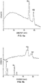
- a monochromatic excitation beam for XRF in such a package can be better understood with reference to the output spectrum of a typical x-ray molybdenum target tube shown in Fig. 5a - showing characteristic lines from the tube's target material at about 17keV, and a broader bremsstrahlung radiation spectrum.
- the secondary x-rays emitted from the sample have two components: the fluorescent characteristic lines of the elements in the sample and scattered x-rays from the source as shown in Fig. 5b .
- An energy dispersive (ED) detector measures the sum of the two. Therefore, the fluorescence signals of trace elements in the sample can be obscured by the background.
- Fig. 6a illustrates the spectrum of the beam that impinges on the sample. Therefore the spectrum of the beam that impinges on the sample is much simpler, as shown in Fig. 6a .
- the spectrum that emerges from the sample now has a much lower background at all energies except at the Compton scattering region.
- Fig. 6b illustrates the scattering spectrum with the fluorescence signal from a sample. The trace element signals undetected in Fig. 5b are now clearly detectable.
- multiple optics 223 and 225 (and others) of apparatus 200 are different, i.e., are tuned to different parts of the x-ray energy spectrum, to optimize element detection and quantification in respective areas of the x-ray energy band.
- the excitation energy must be at or above the element's x-ray absorption edge. Causing all of the elements of interest to fluoresce therefore requires an excitation energy above the absorption edges of all of the elements of interest.
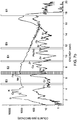
- this graph shows initially that an optic producing monochromatic excitation improves elemental detection by orders of magnitude (trace 710) versus the conventional polychromatic excitation (trace 720).
- a characteristic energy line E1 from, e.g., a molybdenum target x-ray tube at approximately 17keV is focused to the sample using a point-focusing, monochromating optic as discussed above, generally causing all elements having fluorescent lines of interest lower that 17keV to fluoresce (e.g., trace 710). Its excitation effect gradually diminishes, however, for elements having fluorescence lines much lower (e.g., less than 10keV in this example).
- the additional optic(s) of the present invention can be employed to simultaneously capture the non-characteristic, broad bremsstrahlung energy transmitted from the same x-ray tube, and provide additional lines of excitation energy, at e.g., energies E2, E3, E4, E5 ... each line from a respective point-focusing, monochromating optic.
- energies higher than 17keV can also be used. This technique can be used for efficient, low-background excitation of various ranges of elements in the periodic table.
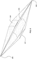
- three optics 223, 225, and 227 provide the 31 keV (from bremsstrallung), the 17keV characteristic molybdenum line, along with the 7keV line (also from bremsstrahlung), respectively.
- Ratios of fluorescence spectra caused by two different excitation energies can also be exploited for additional information about the sample.
- Fig. 9 shows an exemplary excitation of a sample toy with the proposed apparatus in accordance with the present invention, for measuring 10 elements of interest.
- Multi-element optics can be used in accordance with the above-mentioned U.S. Patent 7,035,374 .
- layered optics can be used, in accordance with multilayer techniques, and/or multi-crystal-layer techniques as disclosed in U.S. Patent Application No. 11/941,377 filed on November 16, 2007 entitled X-RAY FOCUSING OPTIC HAVING MULTIPLE LAYERS WITH RESPECTIVE CRYSTAL ORIENTATIONS.
- DCCs are referred to herein as LDCCs.
- the rocking curve width of the optic can be designed to be 2 to 5 times higher than single layer DCC optics.
- the rocking curve can be narrow such that its efficiency is reduced by the finite size of a typical x-ray point source.
- the LDCC can be designed to match the source size and improve the transmitted flux for focusing characteristic lines as well.
- the LDCC optics may also work better for higher energy photons.
- a more layered structure can be built for high energy x-rays due to reduced absorption.
- the useful energy range for the LDCC is expected to be 6 - 50 keV.
- three LDCC optics can be used to provide a trichromatic focused beam from a small spot Cu target source.
- the first LDCC focuses Cu K ⁇ 1 8.04keV characteristic x-rays to the sample spot.
- the spot size is approximately 50 ⁇ m to 75 ⁇ m.
- the Cu LDCC covers the excitation for elements from Silicon (Si) to Manganese (Mn) including Cr.
- the second LDCC selects and focuses a band of bremsstrahlung centered at 16 keV for Hg, Pb and Br excitation.
- the third LDCC selects and focuses a band of bremsstrahlung centered at 28 keV for Cd excitation.
- the two bremsstrahlung optics have focused spots of 100 ⁇ m to 300 ⁇ m.
- the bandwidth of the bremsstrahlung optics are designed to be about 1-2 % of the focusing energy.
- a PIN diode detector is used for EDXRF spectrometry.
- a shutter scheme can be constructed between the x-ray source and the optics, or between the optics and the sample (as discussed above) to have the option to turn the beam from each optic on and off, in any combination.
- a camera and/or laser spot can be placed in the center of the three optics in order to visually locate the measurement spot. The camera will also be used to store the image along with the spectral data.
- a small laser-height gauge is used to aid in the positioning of the sample at the focal point.
- the trend toward increasing global regulation of toxins presents an opportunity for such highly aligned systems as a platform technology to address a number of currently important applications.
- the disclosed system provides several advantages over previous toxin detection technologies with the combined ability to non-destructively detect very low levels, isolate small features, and give reliable results across a wide range of toxic elements.
- Conventional XRF analyzers and more standard analytical chemistry techniques do not possess the needed combination of reliable results, some level of portability, and low cost per test needed in today's tightening regulatory environment. Areas that are in need of these attributes include consumer products, electronics, air quality monitoring, body fluids, food products, and pharmaceuticals.
- Many of these applications can, in principle, share a common hardware and software platform, to hasten new product introductions, lower manufacturing costs, and provide higher quantities of precision instruments.
Landscapes
- Physics & Mathematics (AREA)
- Chemical & Material Sciences (AREA)
- Immunology (AREA)
- Pathology (AREA)
- Analytical Chemistry (AREA)
- Biochemistry (AREA)
- General Health & Medical Sciences (AREA)
- General Physics & Mathematics (AREA)
- Health & Medical Sciences (AREA)
- Life Sciences & Earth Sciences (AREA)
- Crystallography & Structural Chemistry (AREA)
- Spectroscopy & Molecular Physics (AREA)
- Engineering & Computer Science (AREA)
- General Engineering & Computer Science (AREA)
- High Energy & Nuclear Physics (AREA)
- Analysing Materials By The Use Of Radiation (AREA)
Description
- This application claims the benefit of
United States provisional patent application Serial No. 61/033,899, filed March 5, 2008 United States provisional patent application Serial No. 61/039,220, filed March 25, 2008 United States provisional patent application Serial No. 61/042,974, filed April 7, 2008 - The present invention relates generally to x-ray analysis systems, and more particularly, to x-ray source assemblies providing multiple excitation energies to improve detection and analysis of multiple elements in homogeneous and heterogeneous sample structures.
- There is an emerging need to provide manufactured products of all types in which the levels of toxins is minimized or completely eliminated. This need has a clear underlying medical basis and is accelerated by fear and pending legislation - the results of many recent well-publicized cases of toxins in manufactured products (e.g., lead in toys). The costs of unsafe products go well beyond the health impact to include significant loss of business, permanent damage to brands and corporate image, and increased levels of corporate and personal liability.
- In response to these problems, there is a growing trend of increasingly strict environmental and health regulations of consumer products around the world. The list of products regulated is rapidly increasing and the types and permitted levels of toxins are becoming more restrictive. Some industry players are going beyond the regulations for the products they distribute, by mandating even cleaner products in their supply chain. Regulations are effectively aimed at decreasing direct human exposure to toxins by reducing toxins in our environment. Several stricter standards can be traced to European environmental directives that began in the early 1990s, starting with regulations in packaging materials and batteries. In subsequent years, reductions on hazardous substances were introduced by the EU for automobiles (ELV) and two directives related to electronics (Restriction of Hazardous Substances or RoHS and Waste Electrical and Electronic Equipment or WEEE). Pending U.S. Federal legislation lowers allowable lead levels in paint on toys by a factor of six and threatens criminal prosecution for companies that violate with penalties ranging from $10 million to $100 million for a single violation. In addition, nine other known toxins are targeted for restriction, including: mercury, arsenic, cadmium, barium, and chromium.
- The spread of such human health and environmental initiatives are having profound global implications on the way products are designed, manufactured, and ultimately discarded or recycled.
- Current measurement methods for toxins in manufactured products do not meet the needs of the supply chain, from the factories to the ultimate consumers. Identification and measurement of toxins are needed at each step of the chain, from raw materials, to components, to finished goods. While raw-material measurements are most efficient for factories, distribution channels typically require measurements on the final product. New techniques are urgently needed to accurately, quickly, consistently, and cost-effectively measure toxins at each stage, with minimal interruptions in the flow of manufacturing and distribution of the goods. Because toys and other manufactured products often have small painted features (pigments are often the source of the toxins), it is necessary to measure small areas while differentiating the paint from the base material.
- Existing low-cost methods of toxin detection are generally ineffective, e.g., swab tests. Higher-cost methods that provide the requisite accuracy are expensive and time consuming. These sometimes involve: manually scraping samples, digesting them in acids at elevated temperature and pressure, introducing them into a combustion chamber, and analyzing the combustion product. One widely used method today is inductively coupled plasma optical emission spectroscopy (ICP-OES) - a method which is expensive, destructive, and slow. Alternatively, handheld x-ray fluorescence (XRF) guns are rapid and nondestructive, but are only reliable for higher than regulated concentrations, and are averaged across large sample areas, and cannot separately evaluate paint layers.
- As discussed further below, the present invention provides a measurement solution having fast, accurate results for toxins in manufactured products, enabled by sophisticated proprietary x-ray optics. Such proprietary optics typically provide 10 - 1,000x improvements in the ability to focus x-rays; and optic-enabled analyzers are especially suited for these targeted markets - moving measurements from the lab into the factory, field, and clinic.
- In x-ray analysis systems, high x-ray beam intensity and small beam spot sizes are important to reduce sample exposure times, increase spatial resolution, and consequently, improve the signal-to-background ratio and overall quality of x-ray analysis measurements. In the past, expensive and powerful x-ray sources, such as rotating anode x-ray tubes or synchrotrons, were the only options available to produce high-intensity x-ray beams, in the laboratory. Recently, the development of x-ray optic devices has made it possible to collect the diverging radiation from an x-ray source by focusing the x-rays. A combination of x-ray focusing optics and small, low-power x-ray sources can produce x-ray beams with intensities comparable to those achieved with more expensive devices. As a result, systems based on a combination of small, inexpensive x-ray sources, excitation optics, and collection optics have greatly expanded the availability and capabilities of x-ray analysis equipment in, for example, small laboratories and in the field, factory, or clinic, etc.
- Monochromatization of x-ray beams in the excitation and/or detection paths is also useful to excite and/or detect very precise portions of the x-ray energy spectrum corresponding to various elements of interest (lead, etc.). X-ray monochromatization technology is based on diffraction of x-rays on optical crystals, for example, germanium (Ge) or silicon (Si) crystals. Curved crystals can provide deflection of diverging radiation from an x-ray source onto a target, as well as providing monochromatization of photons reaching the target. Two common types of curved crystals are known as singly-curved crystals and doubly-curved crystals (DCCs). Using what is known in the art as Rowland circle geometry, singly-curved crystals provide focusing in two dimensions, leaving x-ray radiation unfocused in the third or orthogonal plane. Doubly-curved crystals provide focusing of x-rays from the source to a point target in all three dimensions. This three-dimensional focusing is referred to in the art as "point-to-point" focusing.
- Commonly-assigned
U.S. Patent Nos. 6,285,506 and7,035,374 disclose various configurations of curved x-ray optics for x-ray focusing and monochromatization. In general, these patents disclose a flexible layer of crystalline material (e.g., Si) formed into curved optic elements. The monochromating function, and the transmission efficiency of the optic are determined by the crystal structure of the optic. - The ability to focus x-ray radiation to smaller spots with higher intensities, using focusing and monochromating x-ray optics, has enabled reductions in the size and cost of x-ray tubes, and x-ray systems have therefore been proliferating beyond the laboratory to in-situ, field uses. Commonly-assigned
U.S. Patents Nos. 6,934,359 and7,702,439 disclose monochromatic wavelength dispersive x-ray fluorescence (MWD XRF) techniques and systems, using doubly curved crystal optics in the excitation and/or detection paths. The x-ray optic-enabled systems described in these patents have enjoyed widespread success beyond the laboratory, for measuring sulfur in petroleum fuels in a variety of refinery, terminal, and pipeline environments. - In such systems, precise optic alignment along an axis defined by a source and sample spot may be required, as illustrated in above-mentioned
U.S. Patent No. 7,035,374 , which proposes an arrangement of curved, monochromating optics around a central axis operating according to Bragg diffraction conditions.Fig. 1a is a representative isometric view of this x-rayoptic arrangement 150 having a curved optic 152, anx-ray source location 154, and anx-ray target location 156.X-ray source location 154 andx-ray target location 156 define a source-to-target transmission axis 162. Optic 152 may include a plurality of individualoptic crystals 164, all of which may be arranged symmetrically aboutaxis 162. -
Fig. 1b is a cross-sectional view taken along section lines 1b--1b ofFig. 1a , wherein the surface of optic 152, x-raysource location 154, andx-ray target location 156 define one or more Rowland (or focal)circles individual crystals 164, will vary with the position of the surface ofoptic crystal 152, for example, the variation of the toroidal position onoptic crystal 152. - The internal atomic diffraction planes of
optic crystal 152 also may not be parallel to its surface. For example, as shown inFIG. 1b , the atomic diffraction planes ofcrystal 152 make an angle γ1 with the surface upon which x-rays are directed, at the point oftangency 158 of the surface and its correspondingoptic circle U.S. Pat. No. 6,285,506 , entitled "Curved Optical Device and Method of Fabrication." - All
individual crystals 164 should be aligned to the source-to-target axis 162, for proper Bragg conditions. Improvement in optic alignment, especially for such multiple-crystal optics, therefore remains an important area of interest. Another issue, which particularly affects volume manufacturing, is the need to align disparate components which may be purchased from different vendors. For example, the x-ray tubes, when purchased in quantities from a vendor, may have source x-ray spots which are not consistently centered relative to their own housings. Re-centering these x-ray tube spots is necessary, as an initial step in the alignment process for an entire x-ray source assembly. - Various optic/source combinations have already been proposed to handle thermal stability, beam stability, and alignment issues, such as those disclosed in commonly assigned
U.S. Patents Nos. 7,110,506 ;7,209,545 ; and7,257,193 . In particular, Patents Nos.7,209,545 (entitled "X-Ray Source Assembly Having Enhanced Output Stability, and Fluid Stream Analysis Applications Thereof') and7,257,193 (entitled "X-Ray Source Assembly Having Enhanced Output Stability Using Tube Power Adjustments and Remote Calibration") address certain tube/optic alignment problems during source operation with real-time, corrective feedback approaches for alignment between the tube focal spot, optic, and output focal spot. Sensors are used to detect various operating conditions, and mechanical and/or thermal adjustments are made to correct for instabilities, including misalignments. These types of systems are necessary and valuable for certain applications, but can also increase the cost and complexity of fielded systems. - The above-described XRF technology and systems have been useful in single element analyzers for measuring generally homogeneous sample structure (e.g., sulfur in petroleum products). However, the measurement of toxins in manufactured products presents an additional level of challenges. First, an instrument should have the capability to measure more than one element simultaneously or nearsimultansously, from a relatively confined list of about 10 toxic elements, discussed above. Moreover, manufactured products are likely to be heterogeneous in nature, requiring small spot resolution, as well as the ability to detect toxins in one of a number of heterogeneous layers (e.g., the level of lead in a paint layer and a substrate layer beneath the paint).
- Improved x-ray analysis method and systems are required, therefore, to address the problems associated with measuring multiple toxins in potentially heterogeneous samples, to enable in-the-factory and/or in-the-field measurement of toxins in manufactured products.
-
JP2002195963 JPH1123797 -
-
JP2001194325 - The shortcomings of the prior art are overcome and additional advantages are provided by the present invention, which is defined by the appended claims. The first x-ray optic may monochromate characteristic energy from the source spot, and the second x-ray optic may monochromate bremsstrahlung energy from the source spot. The x-ray optics are curved diffracting optics, for receiving the diverging x-ray beam from the x-ray tube and focusing the beam at the sample spot. Detection is also provided to detect and measure various toxins in, e.g., manufactured products including toys and electronics.
- The present inventors have developed these novel and effective techniques to address the growing market need to scrutinize toxins in manufactured goods. Optic-enabled, monochromatic-excited, micro-focus energy-dispersive XRF utilizes the above-discussed advanced x-ray optics together with a low-wattage x-ray tube, commercially available sensors, and proprietary software algorithms in a compact touch-and-shoot design. The optics greatly improve the signal-to-noise and concentrate the intensity in a small spot. The optic-enabled analyzer can nondestructively detect and quantify multiple toxic elements simultaneously in the small features typically found in products such as toys and electronics, regardless of the product's shape, size, or homogeneity. Its simple-to-use design enables the quantifiable measurement of toxin concentrations as low as 1 ppm. The system maintains secure records including clear time-stamped photographic identification of the toy and feature measured, ensuring auditable compliance.
- Doubly Curved Crystal (DCC) monochromating optics can be used to enhance measurement intensities by capturing x-rays from a divergent source and redirecting them into an intense focused beam on the surface of the product. Their small spot size allows the analyzer to inspect small features down to 1.5mm in diameter with no reduction in speed or data quality. This unique capability will distinguish very small features commonly seen in toys and electronics. Regulations require that each material be evaluated separately; the limits are per material and color, not averaging across multiple features.
- The favorable signal-to-noise ratio enabled by the optics provides the analyzer with extremely low limits of detection. This high-performance limit-of-detection increases the reliability of results, hence dramatically reducing the number of false positives or negatives. The analyzer will remain effective even at lowest proposed regulatory limits of 40ppm for lead.
- Paint coatings are of particular interest in the toy market so the toy analyzer has incorporated a dedicated coating optic with optimum energy levels and angles to isolate paint layers. Conventional XRF technologies without optics take an average of the coating and substrate layers that can mask high toxin levels in the paint layer. The toy analyzer can distinguish the composition of the paint coating layer from the substrate.
- The multi-element capability can simultaneously provide results on the most requested toxins in toys and other consumer products. At least 26 different elements can be detected simultaneously using the system, with emphasis on the 10 toxins of greatest interest to manufacturers including Cr, As, Br, Cd, Sb, Ba, Se, Hg, Cl & Pb.
- Further, additional features and advantages are realized through the techniques of the present invention. Other embodiments and aspects of the invention are described in detail herein and are considered a part of the claimed invention.
- The subject matter which is regarded as the invention is defined by the claims at the conclusion of the specification. The foregoing and other objects, features, and advantages of the invention are apparent from the following detailed description taken in combination with the accompanying drawings in which:
-
Figs. 1a-b depict an exemplary arrangement of crystal x-ray optics about an axis, requiring alignment; -
Fig. 2 is a perspective view of an aligned x-ray optic and source assembly, in accordance with one aspect of the present invention; -
Fig. 3 is a sectional view of the assembly ofFig. 2 ; -
Fig. 4 is an exploded view of the assembly ofFig. 2 ; -
Figs. 5a-b show the typical characteristic line and bremsstrahlung radiation from an x-ray tube; -
Figs. 6a-b show the impact of monochromating the x-ray tube energy and the improved detection results; -
Figs. 7a-b show the various element peaks due to monochromated excitation energy, and the potential placement of multiple, monochromatic excitation energy beams, in accordance with the present invention; -
Fig. 8 is a schematic of the x-ray paths established by three different focusing, monochromating x-ray optics in accordance with the present invention; and -
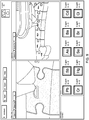
Fig. 9 shows an exemplary excitation of a sample toy with the proposed apparatus in accordance with the present invention, for measuring 10 elements of interest. - In accordance with the present invention,
Figs 2-4 depict in various views (using like numerals to refer to like elements) a highly-aligned x-ray optic andsource assembly 200 in accordance with the present invention. - The assembly includes a
first section 210,second section 220, andthird section 230, which together align anx-ray tube 240 to asample spot 250, along a central transmission axis Z. Also aligned along this axis are multipleoptic carriage assemblies -
First housing section 210 includes adjustable tube-mountingfeatures tube 240 thereby ensuring centering oftube x-ray spot 242 centrally along a central axis of section 210 (not shown). As discussed below, further attachment ofassembly sections x-ray tube 240, they may be shipped with slightly off-center tube spots from the manufacturer, and therefore are required to be re-centered alongsection 210's axis using adjustable mounting features 212 and 214 (e.g., set screws). - The ability to provide an efficient, economical, portable analysis capability depends to a large extent upon x-ray tube and optic technology. In that regard, certain tube and optic technology can be combined for smaller, portable systems, e.g., a compact, electron-bombardment x-ray tube. One example of this type of x-ray tube is available from Oxford Instruments - model # 5011, which operates at less than 100 watts (i.e., 75 watts) at a cost of less than $1500 per tube, in contrast to higher-power, laboratory sources which can cost many thousands, or hundreds of thousands of dollars - which is cost prohibitive for many applications. Another example is the Varian VF-50J (similar to that depicted here), tubular in shape, and which operates at 50 watts or less, at a cost of several thousand dollars each, with a molybdenum material, as discussed further below.
-
Second housing section 220 includes additional alignment features. First,complimentary mating surfaces 216 and 228 (Fig. 4 ) are provided to align the axes ofsections tube section 210 intosection 220.Sections -
Sections tubular sections perimeter mating surface 216 ofsection 210 and inner perimeter mating surface 218 ofsection 220. The fully enclosed tubular sections also provide required x-ray shielding. - Second,
section 220 also accommodates the attachment ofoptic carriages x-ray optics section 220 and, ultimately, to transmission axis Z. X-ray beam focusing and monochromating can be accomplished using certain focusing optics, for example, curved crystal monochromating optics such as those disclosed in commonly assignedU.S. Patents Nos. 6,285,506 ;6,317,483 ; and7,035,374 ; and/or multilayer optics. The curved monochromating optics (discussed above with reference toFigs. 1a-b ) require precise alignment along, and a certain distance from, the transmission axis to meet the appropriate Bragg conditions of interest. Also of particular interest is the requirement to align multiple such optics (e.g., 223, 225, 227) along a single Z axis. - The exemplary
curved crystal optics x-ray tube spot 242, and focus diffracted beams to samplespot 250. Thecarriages shim 229, and/or other spacing adjusters (set screws, etc) can be employed to ensure proper optic alignment (Figs. 3-4 ). Notably, these types of optics, to maintain their Bragg condition conditions, may be mounted along a surface of the second housing section, while separated from the transmission axis Z. -
Third housing section 230 includes an aperture at its point, which requires alignment to transmission axis Z for proper illumination ofsample spot 250 with the focused x-ray beams from the optics. Acone 231 within this section may also be included for additional shielding, rigidly or adjustably mounted tosection 230.Section 230 may also have rigidly mounted thereon an exemplary energy-dispersive detector 260 which itself requires close alignment to transmission axis Z. To effect alignment ofsection 230 withsections 220 and 210 (thereby completing alignment of the entire source assembly along transmission axis Z), complimentary mating surfaces and/or adjustable mounting means (e.g., set screws) can be employed to alignhousing section 230 tosection 220 and therefore tosection 210.Section 230 and/orcone 231 can also be adjusted in directions orthogonal to the transmission axis Z. Other types of detectors (e.g., wavelength dispersive) may also be used with or without similar optics in the detection path. Additional issues should be considered regarding detector alignment.Energy dispersive detector 260 may also have its own focal spot in space, which also requires alignment to beam/sample focal spot 250 (e.g.,Figs. 2-3 ). (Sample spot 250 may be at the surface, or below the surface, of the sample; depending on the focal point of the x-ray beam.) As shown, detector is mounted to cone 31, which may have adjustable mounting means (shims, set screws, etc.), as well as a predetermined mating surface, which ensure alignment of the detector. Using this approach, end-to-end alignment of the x-ray tube, optic(s), sample spot, and detector is provided. - Also shown is an automated shutter system having its
own carriage 272,motor 274 andshutter plates 276. This shutter can be used for x-ray safety purposes (i.e., full blocking shutter), and also for selecting which x-ray beams (from the optics) should be applied to the sample, in any mix ranging from individual non-simultaneous excitation, to full simultaneous excitation, or any mix thereof. This is especially important for the multiple-energy excitation techniques discussed below. - Other blocking
slits - The above approach provides a highly aligned x-ray optic and source assembly using various techniques to ensure alignment of disparate components (optics, x-ray tubes, detectors, etc) in a small, rugged, portable, analyzer for in-situ, on-line, measurements in industrial process, clinical, and field settings. Volume manufacturing is enabled, even when components of varying dimensional tolerances are introduced into the production. Moreover, the highly aligned assembly provides the precision alignment required by focusing, diffractive optics according to Bragg conditions. Any mis-alignment of the optics will directly impact the precision of the device.
- The benefit of using a monochromatic excitation beam for XRF in such a package can be better understood with reference to the output spectrum of a typical x-ray molybdenum target tube shown in
Fig. 5a - showing characteristic lines from the tube's target material at about 17keV, and a broader bremsstrahlung radiation spectrum. When this x-ray beam impinges on a sample, the secondary x-rays emitted from the sample have two components: the fluorescent characteristic lines of the elements in the sample and scattered x-rays from the source as shown inFig. 5b . An energy dispersive (ED) detector measures the sum of the two. Therefore, the fluorescence signals of trace elements in the sample can be obscured by the background. Using a point-focusing, monochromatic optic between the source and the sample, the optic only diffracts the tube's characteristic line from the source. Therefore the spectrum of the beam that impinges on the sample is much simpler, as shown inFig. 6a . The spectrum that emerges from the sample now has a much lower background at all energies except at the Compton scattering region.Fig. 6b illustrates the scattering spectrum with the fluorescence signal from a sample. The trace element signals undetected inFig. 5b are now clearly detectable. - In the present invention,
multiple optics 223 and 225 (and others) ofapparatus 200 are different, i.e., are tuned to different parts of the x-ray energy spectrum, to optimize element detection and quantification in respective areas of the x-ray energy band. In general, for an element to fluoresce and therefore be subject to detection and measurement, the excitation energy must be at or above the element's x-ray absorption edge. Causing all of the elements of interest to fluoresce therefore requires an excitation energy above the absorption edges of all of the elements of interest. - With reference to the comparative graph of
Fig. 7a , this graph shows initially that an optic producing monochromatic excitation improves elemental detection by orders of magnitude (trace 710) versus the conventional polychromatic excitation (trace 720). - As discussed above, and with further reference to
Fig. 7b , a characteristic energy line E1 from, e.g., a molybdenum target x-ray tube at approximately 17keV, is focused to the sample using a point-focusing, monochromating optic as discussed above, generally causing all elements having fluorescent lines of interest lower that 17keV to fluoresce (e.g., trace 710). Its excitation effect gradually diminishes, however, for elements having fluorescence lines much lower (e.g., less than 10keV in this example). - The additional optic(s) of the present invention can be employed to simultaneously capture the non-characteristic, broad bremsstrahlung energy transmitted from the same x-ray tube, and provide additional lines of excitation energy, at e.g., energies E2, E3, E4, E5 ... each line from a respective point-focusing, monochromating optic. Energies higher than 17keV (not shown) can also be used. This technique can be used for efficient, low-background excitation of various ranges of elements in the periodic table.
- In the
particular system embodiment 200 shown herein and with further reference to the x-ray path diagram ofFig. 8 , threeoptics - These lines provide optimized excitation of the following approximate ranges of elements of interest from the periodic table (listed along with their atomic numbers):
- 31keV: From about Zr (40) to Te (52)
- 17keV: From about Cl (17) to Br (35); Rb(37) to Sr(38); Zr(40);
- Cs(55) to Bi(83); Th(90); U(92)
- 7keV: From about Al (13) to Co (27)
- By using different optics, different excitation angles and/or energies are simultaneously (or sequentially, or any mix thereof using a shutter system) applied to the sample. Because different energies cause different fluorescence effects, more information can be determined in the detection path. For example, higher energies penetrate deeper depths and can be used to detect substrate (rather than painted) layers in the material. Moreover, even though lower energies may penetrate the paint levels, the resultant fluorescence may not, giving more insight into material makeup.
- Certain elements exist in the energy band at spacings that generally exceed a detector's ability to resolve (e.g., Cd and Sn), and in fact have overlapping K/L lines and absorption energies. And tin (Sn), a commonly used lead substitute, may mask the cadmium in the detection path. Therefore, excitation just below the absorption of the higher element (Sn), thereby not exciting the tin but effectively exciting all the cadmium, can be used to isolate the lower element (Cd).
- Ratios of fluorescence spectra caused by two different excitation energies can also be exploited for additional information about the sample.
-
Fig. 9 shows an exemplary excitation of a sample toy with the proposed apparatus in accordance with the present invention, for measuring 10 elements of interest. - Multi-element optics (e.g., 223) can be used in accordance with the above-mentioned
U.S. Patent 7,035,374 . Moreover, layered optics can be used, in accordance with multilayer techniques, and/or multi-crystal-layer techniques as disclosed inU.S. Patent Application No. 11/941,377 filed on November 16, 2007 - In one particular example, three LDCC optics can be used to provide a trichromatic focused beam from a small spot Cu target source. The first LDCC focuses Cu Kα1 8.04keV characteristic x-rays to the sample spot. The spot size is approximately 50µm to 75µm. The Cu LDCC covers the excitation for elements from Silicon (Si) to Manganese (Mn) including Cr. The second LDCC selects and focuses a band of bremsstrahlung centered at 16 keV for Hg, Pb and Br excitation. The third LDCC selects and focuses a band of bremsstrahlung centered at 28 keV for Cd excitation. The two bremsstrahlung optics have focused spots of 100µm to 300µm. The bandwidth of the bremsstrahlung optics are designed to be about 1-2 % of the focusing energy. A PIN diode detector is used for EDXRF spectrometry. A shutter scheme can be constructed between the x-ray source and the optics, or between the optics and the sample (as discussed above) to have the option to turn the beam from each optic on and off, in any combination. A camera and/or laser spot can be placed in the center of the three optics in order to visually locate the measurement spot. The camera will also be used to store the image along with the spectral data. A small laser-height gauge is used to aid in the positioning of the sample at the focal point.
- The trend toward increasing global regulation of toxins presents an opportunity for such highly aligned systems as a platform technology to address a number of currently important applications. The disclosed system provides several advantages over previous toxin detection technologies with the combined ability to non-destructively detect very low levels, isolate small features, and give reliable results across a wide range of toxic elements. Conventional XRF analyzers and more standard analytical chemistry techniques do not possess the needed combination of reliable results, some level of portability, and low cost per test needed in today's tightening regulatory environment. Areas that are in need of these attributes include consumer products, electronics, air quality monitoring, body fluids, food products, and pharmaceuticals. Many of these applications can, in principle, share a common hardware and software platform, to hasten new product introductions, lower manufacturing costs, and provide higher quantities of precision instruments.
- Although preferred embodiments have been depicted and described in detail herein, it will be apparent to those skilled in the relevant art that various modifications, additions, substitutions and the like can be made without departing from the invention, which is solely defined in the following claims.
Claims (5)
- Portable x-ray analysis apparatus (200) for illuminating a sample spot with an x-ray beam, comprising:an x-ray tube (240) tubular in shape having a source spot (242) at one end thereof from which a diverging x-ray beam is produced, the source spot requiring alignment along a transmission axis (Z) passing through the sample spot, wherein the apparatus (200) further comprises:a first housing section (210) to which the x-ray tube is attached along a first axis thereof, the first housing section including adjustable tube-mounting features (212, 214) about its perimeter for adjustably mounting the x-ray tube therein such that the source spot coincides with the first axis, the first housing section further including mating surfaces (228) aligned to the first axis;a second housing section (220) having a second axis coinciding with the transmission axis (Z), and mating surfaces (216) aligned to the second axis; andfirst and second, different x-ray optics (223, 225) attached to the second housing section (220) for receiving the diverging x-ray beam and directing the beam toward the sample spot at different respective energies, the different x-ray optics optic (223, 225) are adjustably mounted to the second housing section (220) by optic carriages (222, 224) for aligning the x-ray optics (223, 225) to the second housing section (220) and to the transmission axis (Z);the first housing section and second housing section being matable along their respective mating surfaces (228, 216) to thereby align the first and second axes with the transmission axis (Z), thereby aligning the source spot, x-ray optics, and sample spot;wherein the first and second housing sections are tubular in shape, and the mating surfaces of the first and second housing sections comprise surface portions in contact with each other upon attachment of the first and second tubular housing sections,wherein the x-ray optics are curved diffracting optics, for receiving the diverging x-ray beam from the x-ray tube and focusing the beam at the sample spot,wherein the x-ray optics are focusing monochromating optics.
- Portable x-ray analysis apparatus in accordance with claim 1, further comprising a third x-ray optic (227) for receiving the diverging x-ray beam and directing the beam toward the sample spot, the third x-ray optic monochromating bremsstrahlung energy from the source spot to a third energy.
- Portable x-ray analysis apparatus in accordance with claim 1, further comprising a third housing section, the third housing section including an aperture along the transmission axis (Z) through which the x-ray beam passes when illuminating the sample spot, the second housing section and third housing section being matable along respective mating surfaces to thereby align the aperture with the transmission axis (Z) and therefore the sample spot, the apparatus further comprising an x-ray detector mounted to the third housing section in alignment with the sample spot.
- Portable x-ray analysis apparatus in accordance with claim 1, wherein the first optic monochromates characteristic energy from the source spot and the second x-ray optic monochromates bremsstrahlung energy from the source spot.
- Portable x-ray analysis apparatus in accordance with claim 1, wherein the focusing monochromatic optics are doubly curved crystal optics or doubly curved multi-layer optics.
Applications Claiming Priority (4)
| Application Number | Priority Date | Filing Date | Title |
|---|---|---|---|
| US3389908P | 2008-03-05 | 2008-03-05 | |
| US3922008P | 2008-03-25 | 2008-03-25 | |
| US4297408P | 2008-04-07 | 2008-04-07 | |
| PCT/US2009/035847 WO2009111454A1 (en) | 2008-03-05 | 2009-03-03 | Xrf system having multiple excitation energy bands in highly aligned package |
Publications (3)
| Publication Number | Publication Date |
|---|---|
| EP2260501A1 EP2260501A1 (en) | 2010-12-15 |
| EP2260501A4 EP2260501A4 (en) | 2014-03-19 |
| EP2260501B1 true EP2260501B1 (en) | 2021-08-25 |
Family
ID=41056347
Family Applications (1)
| Application Number | Title | Priority Date | Filing Date |
|---|---|---|---|
| EP09716373.7A Active EP2260501B1 (en) | 2008-03-05 | 2009-03-03 | Xrf system having multiple excitation energy bands in highly aligned package |
Country Status (7)
| Country | Link |
|---|---|
| US (4) | US8559597B2 (en) |
| EP (1) | EP2260501B1 (en) |
| JP (1) | JP5539906B2 (en) |
| CN (2) | CN105044139B (en) |
| CA (1) | CA2753990C (en) |
| MX (1) | MX2010009713A (en) |
| WO (1) | WO2009111454A1 (en) |
Families Citing this family (63)
| Publication number | Priority date | Publication date | Assignee | Title |
|---|---|---|---|---|
| CN105044139B (en) | 2008-03-05 | 2019-04-23 | X射线光学系统公司 | With the XRF system of multiple excitation energy bands in the packaging of altitude calibration |
| CN102484934A (en) | 2009-04-16 | 2012-05-30 | 埃里克·H·西尔弗 | Monochromatic X-ray method and apparatus |
| WO2012177472A2 (en) * | 2011-06-20 | 2012-12-27 | X-Ray Optical Systems, Inc. | Online monitoring of contaminants in crude and heavy fuels, and refinery applications thereof |
| US9057685B2 (en) | 2011-08-15 | 2015-06-16 | X-Ray Optical Systems, Inc. | Sample viscosity and flow control for heavy samples, and X-ray analysis applications thereof |
| CN103946693B (en) | 2011-10-06 | 2017-05-03 | X射线光学系统公司 | Mobile transport and shielding apparatus for removable x-ray analyzer |
| CN103765201B (en) * | 2011-10-26 | 2017-11-07 | X射线光学系统公司 | Support structure for the X-ray analysis engine and analyzer and highly aligned monochromatic X-ray optics |
| US20150117599A1 (en) | 2013-10-31 | 2015-04-30 | Sigray, Inc. | X-ray interferometric imaging system |
| EP2820666A4 (en) * | 2012-02-28 | 2016-02-17 | X Ray Optical Sys Inc | X-ray analyzer having multiple excitation energy bands produced using multi-material x-ray tube anodes and monochromating optics |
| GB2515468A (en) | 2013-05-24 | 2014-12-31 | Torr Scient Ltd | X-ray source |
| WO2015027225A1 (en) | 2013-08-23 | 2015-02-26 | The Schepens Eye Research Institute, Inc. | Spatial modeling of visual fields |
| US9570265B1 (en) | 2013-12-05 | 2017-02-14 | Sigray, Inc. | X-ray fluorescence system with high flux and high flux density |
| US9390881B2 (en) | 2013-09-19 | 2016-07-12 | Sigray, Inc. | X-ray sources using linear accumulation |
| US10297359B2 (en) | 2013-09-19 | 2019-05-21 | Sigray, Inc. | X-ray illumination system with multiple target microstructures |
| US10269528B2 (en) | 2013-09-19 | 2019-04-23 | Sigray, Inc. | Diverging X-ray sources using linear accumulation |
| US10295485B2 (en) | 2013-12-05 | 2019-05-21 | Sigray, Inc. | X-ray transmission spectrometer system |
| US9448190B2 (en) | 2014-06-06 | 2016-09-20 | Sigray, Inc. | High brightness X-ray absorption spectroscopy system |
| US9449781B2 (en) | 2013-12-05 | 2016-09-20 | Sigray, Inc. | X-ray illuminators with high flux and high flux density |
| USRE48612E1 (en) | 2013-10-31 | 2021-06-29 | Sigray, Inc. | X-ray interferometric imaging system |
| US10304580B2 (en) | 2013-10-31 | 2019-05-28 | Sigray, Inc. | Talbot X-ray microscope |
| US9823203B2 (en) | 2014-02-28 | 2017-11-21 | Sigray, Inc. | X-ray surface analysis and measurement apparatus |
| US9594036B2 (en) | 2014-02-28 | 2017-03-14 | Sigray, Inc. | X-ray surface analysis and measurement apparatus |
| US10401309B2 (en) | 2014-05-15 | 2019-09-03 | Sigray, Inc. | X-ray techniques using structured illumination |
| WO2015200551A1 (en) | 2014-06-24 | 2015-12-30 | Silver Eric H | Methods and apparatus for determining information regarding chemical composition using x-ray radiation |
| DE102014015974B4 (en) * | 2014-10-31 | 2021-11-11 | Baker Hughes Digital Solutions Gmbh | Connection cable for reducing flashover-induced transient electrical signals between the acceleration section of an X-ray tube and a high-voltage source |
| JP6069609B2 (en) * | 2015-03-26 | 2017-02-01 | 株式会社リガク | Double-curved X-ray condensing element and its constituent, double-curved X-ray spectroscopic element and method for producing the constituent |
| US10352880B2 (en) | 2015-04-29 | 2019-07-16 | Sigray, Inc. | Method and apparatus for x-ray microscopy |
| US10295486B2 (en) | 2015-08-18 | 2019-05-21 | Sigray, Inc. | Detector for X-rays with high spatial and high spectral resolution |
| US9966161B2 (en) * | 2015-09-21 | 2018-05-08 | Uchicago Argonne, Llc | Mechanical design of thin-film diamond crystal mounting apparatus with optimized thermal contact and crystal strain for coherence preservation x-ray optics |
| US10677744B1 (en) * | 2016-06-03 | 2020-06-09 | U.S. Department Of Energy | Multi-cone x-ray imaging Bragg crystal spectrometer |
| US10247683B2 (en) | 2016-12-03 | 2019-04-02 | Sigray, Inc. | Material measurement techniques using multiple X-ray micro-beams |
| PL3364421T3 (en) * | 2017-02-17 | 2019-08-30 | Rigaku Corporation | X-ray optical device |
| WO2018175570A1 (en) | 2017-03-22 | 2018-09-27 | Sigray, Inc. | Method of performing x-ray spectroscopy and x-ray absorption spectrometer system |
| JP7296368B2 (en) | 2017-05-19 | 2023-06-22 | イマジン サイエンティフィック,インコーポレイテッド | Monochromatic X-ray imaging system and method |
| US10818467B2 (en) | 2018-02-09 | 2020-10-27 | Imagine Scientific, Inc. | Monochromatic x-ray imaging systems and methods |
| AU2019218240B2 (en) | 2018-02-09 | 2024-09-19 | Imagine Scientific, Inc. | Monochromatic x-ray imaging systems and methods |
| US10578566B2 (en) | 2018-04-03 | 2020-03-03 | Sigray, Inc. | X-ray emission spectrometer system |
| CN112424591B (en) | 2018-06-04 | 2024-05-24 | 斯格瑞公司 | Wavelength dispersive X-ray spectrometer |
| DE112019003777B4 (en) | 2018-07-26 | 2025-09-11 | Sigray, Inc. | HIGH BRIGHTNESS X-RAY REFLECTION SOURCE |
| US10656105B2 (en) | 2018-08-06 | 2020-05-19 | Sigray, Inc. | Talbot-lau x-ray source and interferometric system |
| CN112638261B (en) | 2018-09-04 | 2025-06-27 | 斯格瑞公司 | Systems and methods utilizing filtered x-ray fluorescence |
| US11056308B2 (en) | 2018-09-07 | 2021-07-06 | Sigray, Inc. | System and method for depth-selectable x-ray analysis |
| WO2020056281A1 (en) | 2018-09-14 | 2020-03-19 | Imagine Scientific, Inc. | Monochromatic x-ray component systems and methods |
| JP7182749B2 (en) | 2019-09-03 | 2022-12-02 | シグレイ、インコーポレイテッド | System and method for computed tomography fluorescence X-ray imaging |
| CN110797744B (en) * | 2019-12-05 | 2024-11-22 | 中国工程物理研究院激光聚变研究中心 | A monochromator for pulsed soft X-ray calibration |
| WO2021118773A1 (en) | 2019-12-13 | 2021-06-17 | Schlumberger Technology Corporation | Measurement of metal or alloy coating |
| US12007226B2 (en) | 2019-12-13 | 2024-06-11 | Schlumberger Technology Corporation | Measurement of thickness of scale or corrosion |
| US11175243B1 (en) | 2020-02-06 | 2021-11-16 | Sigray, Inc. | X-ray dark-field in-line inspection for semiconductor samples |
| US11217357B2 (en) | 2020-02-10 | 2022-01-04 | Sigray, Inc. | X-ray mirror optics with multiple hyperboloidal/hyperbolic surface profiles |
| WO2021237237A1 (en) | 2020-05-18 | 2021-11-25 | Sigray, Inc. | System and method for x-ray absorption spectroscopy using a crystal analyzer and a plurality of detector elements |
| WO2022061347A1 (en) | 2020-09-17 | 2022-03-24 | Sigray, Inc. | System and method using x-rays for depth-resolving metrology and analysis |
| US12480892B2 (en) | 2020-12-07 | 2025-11-25 | Sigray, Inc. | High throughput 3D x-ray imaging system using a transmission x-ray source |
| KR20260030946A (en) | 2020-12-07 | 2026-03-06 | 시그레이, 아이엔씨. | High throughput 3d x-ray imaging system using a transmission x-ray source |
| CA3166557A1 (en) * | 2021-07-01 | 2023-01-01 | Eclipse Orthopaedics, Llc | Surgical viewing system |
| WO2023168204A1 (en) | 2022-03-02 | 2023-09-07 | Sigray, Inc. | X-ray fluorescence system and x-ray source with electrically insulative target material |
| US11992350B2 (en) | 2022-03-15 | 2024-05-28 | Sigray, Inc. | System and method for compact laminography utilizing microfocus transmission x-ray source and variable magnification x-ray detector |
| WO2023215204A1 (en) | 2022-05-02 | 2023-11-09 | Sigray, Inc. | X-ray sequential array wavelength dispersive spectrometer |
| DE112024000873T5 (en) | 2023-02-16 | 2026-01-15 | Sigray, Inc. | X-ray detector system with at least two stacked flat Bragg diffractors |
| US12181423B1 (en) | 2023-09-07 | 2024-12-31 | Sigray, Inc. | Secondary image removal using high resolution x-ray transmission sources |
| US12429437B2 (en) | 2023-11-07 | 2025-09-30 | Sigray, Inc. | System and method for x-ray absorption spectroscopy using spectral information from two orthogonal planes |
| WO2025151383A1 (en) | 2024-01-08 | 2025-07-17 | Sigray, Inc. | X-ray analysis system with focused x-ray beam and non-x-ray microscope |
| WO2025155719A1 (en) | 2024-01-18 | 2025-07-24 | Sigray, Inc. | Sequential array of x-ray imaging detectors |
| WO2025174966A1 (en) | 2024-02-15 | 2025-08-21 | Sigray, Inc. | System and method for generating a focused x‑ray beam |
| CN118050387B (en) * | 2024-04-16 | 2024-07-12 | 安徽吸收谱仪器设备有限公司 | Multi-band synchronous scanning X-ray absorption spectrum device and experimental method |
Citations (3)
| Publication number | Priority date | Publication date | Assignee | Title |
|---|---|---|---|---|
| US3355921A (en) * | 1963-12-27 | 1967-12-05 | Schloemann Ag | Shaping stand for the production of helically welded tubes |
| JPH1123797A (en) * | 1997-07-09 | 1999-01-29 | Rigaku Ind Co | Spectroscope of cylindrical crystal type and manufacture thereof |
| JP2001194325A (en) * | 2000-01-06 | 2001-07-19 | Ours Tex Kk | Device and method for x-ray analysis |
Family Cites Families (14)
| Publication number | Priority date | Publication date | Assignee | Title |
|---|---|---|---|---|
| JPH0769477B2 (en) * | 1990-09-05 | 1995-07-31 | 理学電機工業株式会社 | X-ray spectrometer |
| JP2699134B2 (en) * | 1992-12-03 | 1998-01-19 | 花王株式会社 | X-ray fluorescence analysis method and apparatus |
| US6023496A (en) * | 1997-04-30 | 2000-02-08 | Shimadzu Corporation | X-ray fluorescence analyzing apparatus |
| JP3843601B2 (en) * | 1997-04-30 | 2006-11-08 | 株式会社島津製作所 | X-ray fluorescence analyzer |
| US6014423A (en) * | 1998-02-19 | 2000-01-11 | Osmic, Inc. | Multiple corner Kirkpatrick-Baez beam conditioning optic assembly |
| JP3498689B2 (en) * | 2000-07-31 | 2004-02-16 | 株式会社島津製作所 | Monochromator for monochrome source excitation and X-ray fluorescence analyzer |
| US6493421B2 (en) | 2000-10-16 | 2002-12-10 | Advanced X-Ray Technology, Inc. | Apparatus and method for generating a high intensity X-ray beam with a selectable shape and wavelength |
| JP2002195963A (en) * | 2000-12-25 | 2002-07-10 | Ours Tex Kk | X-ray spectroscope apparatus and x-ray analyzing apparatus |
| EP1402541B1 (en) * | 2001-06-19 | 2006-08-16 | X-Ray Optical Systems, Inc. | Wavelength dispersive xrf system using focusing optic for excitation and a focusing monochromator for collection |
| AU2002364525A1 (en) * | 2001-12-04 | 2003-06-17 | X-Ray Optical Systems, Inc. | X-ray fluorescence analyser for analysing fluid streams using a semiconductor-type detector and focusing means |
| JP2004184314A (en) * | 2002-12-05 | 2004-07-02 | Mitsubishi Electric Corp | X-ray fluorescence analyzer |
| US7317784B2 (en) | 2006-01-19 | 2008-01-08 | Broker Axs, Inc. | Multiple wavelength X-ray source |
| CN105044139B (en) * | 2008-03-05 | 2019-04-23 | X射线光学系统公司 | With the XRF system of multiple excitation energy bands in the packaging of altitude calibration |
| US7738630B2 (en) * | 2008-03-05 | 2010-06-15 | X-Ray Optical Systems, Inc. | Highly aligned x-ray optic and source assembly for precision x-ray analysis applications |
-
2009
- 2009-03-03 CN CN201510303481.8A patent/CN105044139B/en active Active
- 2009-03-03 MX MX2010009713A patent/MX2010009713A/en active IP Right Grant
- 2009-03-03 US US12/920,641 patent/US8559597B2/en active Active
- 2009-03-03 EP EP09716373.7A patent/EP2260501B1/en active Active
- 2009-03-03 JP JP2010549809A patent/JP5539906B2/en active Active
- 2009-03-03 WO PCT/US2009/035847 patent/WO2009111454A1/en not_active Ceased
- 2009-03-03 CN CN200980111618.2A patent/CN101981651B/en active Active
- 2009-03-03 CA CA2753990A patent/CA2753990C/en active Active
-
2013
- 2013-10-11 US US14/052,078 patent/US9048001B2/en active Active
-
2015
- 2015-06-01 US US14/727,027 patent/US9343193B2/en active Active
-
2016
- 2016-05-16 US US15/155,575 patent/US20160260514A1/en not_active Abandoned
Patent Citations (3)
| Publication number | Priority date | Publication date | Assignee | Title |
|---|---|---|---|---|
| US3355921A (en) * | 1963-12-27 | 1967-12-05 | Schloemann Ag | Shaping stand for the production of helically welded tubes |
| JPH1123797A (en) * | 1997-07-09 | 1999-01-29 | Rigaku Ind Co | Spectroscope of cylindrical crystal type and manufacture thereof |
| JP2001194325A (en) * | 2000-01-06 | 2001-07-19 | Ours Tex Kk | Device and method for x-ray analysis |
Also Published As
| Publication number | Publication date |
|---|---|
| HK1153848A1 (en) | 2012-04-05 |
| US20140105363A1 (en) | 2014-04-17 |
| MX2010009713A (en) | 2011-03-29 |
| US20110170666A1 (en) | 2011-07-14 |
| CA2753990A1 (en) | 2009-09-11 |
| JP2011513751A (en) | 2011-04-28 |
| US8559597B2 (en) | 2013-10-15 |
| WO2009111454A1 (en) | 2009-09-11 |
| US9343193B2 (en) | 2016-05-17 |
| EP2260501A1 (en) | 2010-12-15 |
| US9048001B2 (en) | 2015-06-02 |
| CN105044139A (en) | 2015-11-11 |
| CN101981651A (en) | 2011-02-23 |
| CN105044139B (en) | 2019-04-23 |
| CN101981651B (en) | 2015-07-08 |
| US20160260514A1 (en) | 2016-09-08 |
| JP5539906B2 (en) | 2014-07-02 |
| US20150262722A1 (en) | 2015-09-17 |
| EP2260501A4 (en) | 2014-03-19 |
| CA2753990C (en) | 2017-11-21 |
Similar Documents
| Publication | Publication Date | Title |
|---|---|---|
| US9343193B2 (en) | XRF system having multiple excitation energy bands in highly aligned package | |
| US9449780B2 (en) | X-ray analyzer having multiple excitation energy bands produced using multi-material x-ray tube anodes and monochromating optics | |
| EP1402541B1 (en) | Wavelength dispersive xrf system using focusing optic for excitation and a focusing monochromator for collection | |
| US10256002B2 (en) | Support structure and highly aligned monochromatic X-ray optics for X-ray analysis engines and analyzers | |
| WO2013061676A1 (en) | X-ray spectrometry detector device | |
| JP2005512020A5 (en) | ||
| US7738630B2 (en) | Highly aligned x-ray optic and source assembly for precision x-ray analysis applications | |
| KR20160067527A (en) | Apparatus and method for fine pattern measuring Micro-XRF | |
| HK1153848B (en) | Xrf system having multiple excitation energy bands in highly aligned package | |
| Bruno et al. | Introduction to Spectroscopy |
Legal Events
| Date | Code | Title | Description |
|---|---|---|---|
| PUAI | Public reference made under article 153(3) epc to a published international application that has entered the european phase |
Free format text: ORIGINAL CODE: 0009012 |
|
| 17P | Request for examination filed |
Effective date: 20100623 |
|
| AK | Designated contracting states |
Kind code of ref document: A1 Designated state(s): AT BE BG CH CY CZ DE DK EE ES FI FR GB GR HR HU IE IS IT LI LT LU LV MC MK MT NL NO PL PT RO SE SI SK TR |
|
| AX | Request for extension of the european patent |
Extension state: AL BA RS |
|
| DAX | Request for extension of the european patent (deleted) | ||
| A4 | Supplementary search report drawn up and despatched |
Effective date: 20140219 |
|
| RIC1 | Information provided on ipc code assigned before grant |
Ipc: G01N 23/223 20060101AFI20140213BHEP |
|
| 17Q | First examination report despatched |
Effective date: 20160205 |
|
| STAA | Information on the status of an ep patent application or granted ep patent |
Free format text: STATUS: EXAMINATION IS IN PROGRESS |
|
| GRAP | Despatch of communication of intention to grant a patent |
Free format text: ORIGINAL CODE: EPIDOSNIGR1 |
|
| STAA | Information on the status of an ep patent application or granted ep patent |
Free format text: STATUS: GRANT OF PATENT IS INTENDED |
|
| INTG | Intention to grant announced |
Effective date: 20210421 |
|
| GRAS | Grant fee paid |
Free format text: ORIGINAL CODE: EPIDOSNIGR3 |
|
| GRAA | (expected) grant |
Free format text: ORIGINAL CODE: 0009210 |
|
| STAA | Information on the status of an ep patent application or granted ep patent |
Free format text: STATUS: THE PATENT HAS BEEN GRANTED |
|
| AK | Designated contracting states |
Kind code of ref document: B1 Designated state(s): AT BE BG CH CY CZ DE DK EE ES FI FR GB GR HR HU IE IS IT LI LT LU LV MC MK MT NL NO PL PT RO SE SI SK TR |
|
| REG | Reference to a national code |
Ref country code: GB Ref legal event code: FG4D |
|
| REG | Reference to a national code |
Ref country code: CH Ref legal event code: EP |
|
| REG | Reference to a national code |
Ref country code: IE Ref legal event code: FG4D Ref country code: AT Ref legal event code: REF Ref document number: 1424299 Country of ref document: AT Kind code of ref document: T Effective date: 20210915 |
|
| REG | Reference to a national code |
Ref country code: DE Ref legal event code: R096 Ref document number: 602009063980 Country of ref document: DE |
|
| REG | Reference to a national code |
Ref country code: LT Ref legal event code: MG9D |
|
| REG | Reference to a national code |
Ref country code: NL Ref legal event code: MP Effective date: 20210825 |
|
| REG | Reference to a national code |
Ref country code: AT Ref legal event code: MK05 Ref document number: 1424299 Country of ref document: AT Kind code of ref document: T Effective date: 20210825 |
|
| PG25 | Lapsed in a contracting state [announced via postgrant information from national office to epo] |
Ref country code: SE Free format text: LAPSE BECAUSE OF FAILURE TO SUBMIT A TRANSLATION OF THE DESCRIPTION OR TO PAY THE FEE WITHIN THE PRESCRIBED TIME-LIMIT Effective date: 20210825 Ref country code: HR Free format text: LAPSE BECAUSE OF FAILURE TO SUBMIT A TRANSLATION OF THE DESCRIPTION OR TO PAY THE FEE WITHIN THE PRESCRIBED TIME-LIMIT Effective date: 20210825 Ref country code: NO Free format text: LAPSE BECAUSE OF FAILURE TO SUBMIT A TRANSLATION OF THE DESCRIPTION OR TO PAY THE FEE WITHIN THE PRESCRIBED TIME-LIMIT Effective date: 20211125 Ref country code: PT Free format text: LAPSE BECAUSE OF FAILURE TO SUBMIT A TRANSLATION OF THE DESCRIPTION OR TO PAY THE FEE WITHIN THE PRESCRIBED TIME-LIMIT Effective date: 20211227 Ref country code: FI Free format text: LAPSE BECAUSE OF FAILURE TO SUBMIT A TRANSLATION OF THE DESCRIPTION OR TO PAY THE FEE WITHIN THE PRESCRIBED TIME-LIMIT Effective date: 20210825 Ref country code: ES Free format text: LAPSE BECAUSE OF FAILURE TO SUBMIT A TRANSLATION OF THE DESCRIPTION OR TO PAY THE FEE WITHIN THE PRESCRIBED TIME-LIMIT Effective date: 20210825 Ref country code: BG Free format text: LAPSE BECAUSE OF FAILURE TO SUBMIT A TRANSLATION OF THE DESCRIPTION OR TO PAY THE FEE WITHIN THE PRESCRIBED TIME-LIMIT Effective date: 20211125 Ref country code: AT Free format text: LAPSE BECAUSE OF FAILURE TO SUBMIT A TRANSLATION OF THE DESCRIPTION OR TO PAY THE FEE WITHIN THE PRESCRIBED TIME-LIMIT Effective date: 20210825 Ref country code: LT Free format text: LAPSE BECAUSE OF FAILURE TO SUBMIT A TRANSLATION OF THE DESCRIPTION OR TO PAY THE FEE WITHIN THE PRESCRIBED TIME-LIMIT Effective date: 20210825 |
|
| PG25 | Lapsed in a contracting state [announced via postgrant information from national office to epo] |
Ref country code: PL Free format text: LAPSE BECAUSE OF FAILURE TO SUBMIT A TRANSLATION OF THE DESCRIPTION OR TO PAY THE FEE WITHIN THE PRESCRIBED TIME-LIMIT Effective date: 20210825 Ref country code: LV Free format text: LAPSE BECAUSE OF FAILURE TO SUBMIT A TRANSLATION OF THE DESCRIPTION OR TO PAY THE FEE WITHIN THE PRESCRIBED TIME-LIMIT Effective date: 20210825 Ref country code: GR Free format text: LAPSE BECAUSE OF FAILURE TO SUBMIT A TRANSLATION OF THE DESCRIPTION OR TO PAY THE FEE WITHIN THE PRESCRIBED TIME-LIMIT Effective date: 20211126 |
|
| PG25 | Lapsed in a contracting state [announced via postgrant information from national office to epo] |
Ref country code: NL Free format text: LAPSE BECAUSE OF FAILURE TO SUBMIT A TRANSLATION OF THE DESCRIPTION OR TO PAY THE FEE WITHIN THE PRESCRIBED TIME-LIMIT Effective date: 20210825 |
|
| PG25 | Lapsed in a contracting state [announced via postgrant information from national office to epo] |
Ref country code: DK Free format text: LAPSE BECAUSE OF FAILURE TO SUBMIT A TRANSLATION OF THE DESCRIPTION OR TO PAY THE FEE WITHIN THE PRESCRIBED TIME-LIMIT Effective date: 20210825 |
|
| PGFP | Annual fee paid to national office [announced via postgrant information from national office to epo] |
Ref country code: GB Payment date: 20220113 Year of fee payment: 14 |
|
| REG | Reference to a national code |
Ref country code: DE Ref legal event code: R097 Ref document number: 602009063980 Country of ref document: DE |
|
| PG25 | Lapsed in a contracting state [announced via postgrant information from national office to epo] |
Ref country code: SK Free format text: LAPSE BECAUSE OF FAILURE TO SUBMIT A TRANSLATION OF THE DESCRIPTION OR TO PAY THE FEE WITHIN THE PRESCRIBED TIME-LIMIT Effective date: 20210825 Ref country code: RO Free format text: LAPSE BECAUSE OF FAILURE TO SUBMIT A TRANSLATION OF THE DESCRIPTION OR TO PAY THE FEE WITHIN THE PRESCRIBED TIME-LIMIT Effective date: 20210825 Ref country code: EE Free format text: LAPSE BECAUSE OF FAILURE TO SUBMIT A TRANSLATION OF THE DESCRIPTION OR TO PAY THE FEE WITHIN THE PRESCRIBED TIME-LIMIT Effective date: 20210825 Ref country code: CZ Free format text: LAPSE BECAUSE OF FAILURE TO SUBMIT A TRANSLATION OF THE DESCRIPTION OR TO PAY THE FEE WITHIN THE PRESCRIBED TIME-LIMIT Effective date: 20210825 |
|
| PGFP | Annual fee paid to national office [announced via postgrant information from national office to epo] |
Ref country code: FR Payment date: 20220118 Year of fee payment: 14 |
|
| PLBE | No opposition filed within time limit |
Free format text: ORIGINAL CODE: 0009261 |
|
| STAA | Information on the status of an ep patent application or granted ep patent |
Free format text: STATUS: NO OPPOSITION FILED WITHIN TIME LIMIT |
|
| PG25 | Lapsed in a contracting state [announced via postgrant information from national office to epo] |
Ref country code: IT Free format text: LAPSE BECAUSE OF FAILURE TO SUBMIT A TRANSLATION OF THE DESCRIPTION OR TO PAY THE FEE WITHIN THE PRESCRIBED TIME-LIMIT Effective date: 20210825 |
|
| 26N | No opposition filed |
Effective date: 20220527 |
|
| PG25 | Lapsed in a contracting state [announced via postgrant information from national office to epo] |
Ref country code: SI Free format text: LAPSE BECAUSE OF FAILURE TO SUBMIT A TRANSLATION OF THE DESCRIPTION OR TO PAY THE FEE WITHIN THE PRESCRIBED TIME-LIMIT Effective date: 20210825 |
|
| PG25 | Lapsed in a contracting state [announced via postgrant information from national office to epo] |
Ref country code: MC Free format text: LAPSE BECAUSE OF FAILURE TO SUBMIT A TRANSLATION OF THE DESCRIPTION OR TO PAY THE FEE WITHIN THE PRESCRIBED TIME-LIMIT Effective date: 20210825 |
|
| REG | Reference to a national code |
Ref country code: CH Ref legal event code: PL |
|
| REG | Reference to a national code |
Ref country code: BE Ref legal event code: MM Effective date: 20220331 |
|
| PG25 | Lapsed in a contracting state [announced via postgrant information from national office to epo] |
Ref country code: LU Free format text: LAPSE BECAUSE OF NON-PAYMENT OF DUE FEES Effective date: 20220303 Ref country code: LI Free format text: LAPSE BECAUSE OF NON-PAYMENT OF DUE FEES Effective date: 20220331 Ref country code: IE Free format text: LAPSE BECAUSE OF NON-PAYMENT OF DUE FEES Effective date: 20220303 Ref country code: CH Free format text: LAPSE BECAUSE OF NON-PAYMENT OF DUE FEES Effective date: 20220331 |
|
| PG25 | Lapsed in a contracting state [announced via postgrant information from national office to epo] |
Ref country code: BE Free format text: LAPSE BECAUSE OF NON-PAYMENT OF DUE FEES Effective date: 20220331 |
|
| GBPC | Gb: european patent ceased through non-payment of renewal fee |
Effective date: 20230303 |
|
| PG25 | Lapsed in a contracting state [announced via postgrant information from national office to epo] |
Ref country code: GB Free format text: LAPSE BECAUSE OF NON-PAYMENT OF DUE FEES Effective date: 20230303 |
|
| PG25 | Lapsed in a contracting state [announced via postgrant information from national office to epo] |
Ref country code: GB Free format text: LAPSE BECAUSE OF NON-PAYMENT OF DUE FEES Effective date: 20230303 Ref country code: FR Free format text: LAPSE BECAUSE OF NON-PAYMENT OF DUE FEES Effective date: 20230331 |
|
| PG25 | Lapsed in a contracting state [announced via postgrant information from national office to epo] |
Ref country code: HU Free format text: LAPSE BECAUSE OF FAILURE TO SUBMIT A TRANSLATION OF THE DESCRIPTION OR TO PAY THE FEE WITHIN THE PRESCRIBED TIME-LIMIT; INVALID AB INITIO Effective date: 20090303 |
|
| PG25 | Lapsed in a contracting state [announced via postgrant information from national office to epo] |
Ref country code: MK Free format text: LAPSE BECAUSE OF FAILURE TO SUBMIT A TRANSLATION OF THE DESCRIPTION OR TO PAY THE FEE WITHIN THE PRESCRIBED TIME-LIMIT Effective date: 20210825 Ref country code: CY Free format text: LAPSE BECAUSE OF FAILURE TO SUBMIT A TRANSLATION OF THE DESCRIPTION OR TO PAY THE FEE WITHIN THE PRESCRIBED TIME-LIMIT Effective date: 20210825 |
|
| PG25 | Lapsed in a contracting state [announced via postgrant information from national office to epo] |
Ref country code: TR Free format text: LAPSE BECAUSE OF FAILURE TO SUBMIT A TRANSLATION OF THE DESCRIPTION OR TO PAY THE FEE WITHIN THE PRESCRIBED TIME-LIMIT Effective date: 20210825 |
|
| PG25 | Lapsed in a contracting state [announced via postgrant information from national office to epo] |
Ref country code: MT Free format text: LAPSE BECAUSE OF FAILURE TO SUBMIT A TRANSLATION OF THE DESCRIPTION OR TO PAY THE FEE WITHIN THE PRESCRIBED TIME-LIMIT Effective date: 20210825 |
|
| PGFP | Annual fee paid to national office [announced via postgrant information from national office to epo] |
Ref country code: DE Payment date: 20260319 Year of fee payment: 18 |