EP2260222B1 - Valve assembly - Google Patents
Valve assembly Download PDFInfo
- Publication number
- EP2260222B1 EP2260222B1 EP09730331.7A EP09730331A EP2260222B1 EP 2260222 B1 EP2260222 B1 EP 2260222B1 EP 09730331 A EP09730331 A EP 09730331A EP 2260222 B1 EP2260222 B1 EP 2260222B1
- Authority
- EP
- European Patent Office
- Prior art keywords
- valve
- flow
- assembly
- valve assembly
- accordance
- Prior art date
- Legal status (The legal status is an assumption and is not a legal conclusion. Google has not performed a legal analysis and makes no representation as to the accuracy of the status listed.)
- Not-in-force
Links
- 238000007789 sealing Methods 0.000 claims description 58
- 239000012530 fluid Substances 0.000 claims description 53
- 230000014759 maintenance of location Effects 0.000 claims description 47
- 230000002093 peripheral effect Effects 0.000 claims description 13
- 150000001875 compounds Chemical class 0.000 claims description 10
- 230000015572 biosynthetic process Effects 0.000 claims description 3
- 239000007788 liquid Substances 0.000 description 5
- 235000013361 beverage Nutrition 0.000 description 3
- 230000001154 acute effect Effects 0.000 description 2
- 230000000712 assembly Effects 0.000 description 2
- 238000000429 assembly Methods 0.000 description 2
- 238000001802 infusion Methods 0.000 description 2
- 238000011144 upstream manufacturing Methods 0.000 description 2
- 239000013536 elastomeric material Substances 0.000 description 1
- 230000002708 enhancing effect Effects 0.000 description 1
- 230000009969 flowable effect Effects 0.000 description 1
- 238000012986 modification Methods 0.000 description 1
- 230000004048 modification Effects 0.000 description 1
- 230000000149 penetrating effect Effects 0.000 description 1
- 230000002265 prevention Effects 0.000 description 1
Images




Classifications
-
- F—MECHANICAL ENGINEERING; LIGHTING; HEATING; WEAPONS; BLASTING
- F16—ENGINEERING ELEMENTS AND UNITS; GENERAL MEASURES FOR PRODUCING AND MAINTAINING EFFECTIVE FUNCTIONING OF MACHINES OR INSTALLATIONS; THERMAL INSULATION IN GENERAL
- F16K—VALVES; TAPS; COCKS; ACTUATING-FLOATS; DEVICES FOR VENTING OR AERATING
- F16K15/00—Check valves
- F16K15/14—Check valves with flexible valve members
- F16K15/144—Check valves with flexible valve members the closure elements being fixed along all or a part of their periphery
- F16K15/145—Check valves with flexible valve members the closure elements being fixed along all or a part of their periphery the closure elements being shaped as a solids of revolution, e.g. cylindrical or conical
-
- F—MECHANICAL ENGINEERING; LIGHTING; HEATING; WEAPONS; BLASTING
- F16—ENGINEERING ELEMENTS AND UNITS; GENERAL MEASURES FOR PRODUCING AND MAINTAINING EFFECTIVE FUNCTIONING OF MACHINES OR INSTALLATIONS; THERMAL INSULATION IN GENERAL
- F16K—VALVES; TAPS; COCKS; ACTUATING-FLOATS; DEVICES FOR VENTING OR AERATING
- F16K15/00—Check valves
- F16K15/14—Check valves with flexible valve members
- F16K15/144—Check valves with flexible valve members the closure elements being fixed along all or a part of their periphery
-
- Y—GENERAL TAGGING OF NEW TECHNOLOGICAL DEVELOPMENTS; GENERAL TAGGING OF CROSS-SECTIONAL TECHNOLOGIES SPANNING OVER SEVERAL SECTIONS OF THE IPC; TECHNICAL SUBJECTS COVERED BY FORMER USPC CROSS-REFERENCE ART COLLECTIONS [XRACs] AND DIGESTS
- Y10—TECHNICAL SUBJECTS COVERED BY FORMER USPC
- Y10T—TECHNICAL SUBJECTS COVERED BY FORMER US CLASSIFICATION
- Y10T137/00—Fluid handling
- Y10T137/7722—Line condition change responsive valves
- Y10T137/7837—Direct response valves [i.e., check valve type]
- Y10T137/7838—Plural
- Y10T137/7839—Dividing and recombining in a single flow path
- Y10T137/784—Integral resilient member forms plural valves
Definitions
- the present invention relates generally to a valve assembly configured for controlling fluid flow therethrough in response to a pressure differential which exists across the valve assembly, and more particularly to a check valve assembly including a pressure-responsive, elastomeric valve member which cooperates with an associated valve seat of the assembly for controlling fluid flow, wherein the assembly is configured to minimize reverse fluid flow through the assembly in response to a reverse pressure differential across the assembly.
- Such applications can include an interface between two fluid conduits or the like, wherein pressure-responsive introduction of a fluid from one conduit to the other is desired, while reverse fluid flow is prevented. Similar flow control requirements may exist in connection with typical dispensing applications, such as dispensing of consumer products such as beverages, or other flowable products. Many industrial applications require pressure-responsive fluid flow control with a check valve arrangement, again with it typically being necessary for reverse fluid flow to be minimized or substantially prevented.
- U.S. Patents No. 5,033,655 , No. 5,213,236 , No. 5,271,571 , and No. 6,749,092 illustrate such valve assemblies with these patents, disclosing various applications in which such valve assemblies can be advantageously employed.
- a resilient valve for fluids under pressure wherein the valve includes a housing formed with an inlet and an oppositely-located outlet and a cup-shaped valve member mounted over an axial projection extending from the inlet towards the outlet inside the housing.
- a rim of the member is fixed relatively to the housing whilst the lower portion of the member defines a piston-like part which is connected to the rim by a resilient portion through which fluid can pass to act on the piston-like part on both sides or the resilient portion.
- DE 20 2006 012 645 U1 discloses a valve assembly according to the preamble of claim 1.
- the present invention relates to a valve assembly according to claim 1.
- Claims 2 to 14 refer to specifically advantageous realizations of the subject-matter of claim 1.
- the present invention relates generally to a valve assembly of the above-described type, which assembly can be configured for pressure-responsive operation in the nature of a check valve.
- the present valve assembly is configured to permit pressure-responsive fluid flow in response to a pressure differential across the valve assembly, with features of the present invention particularly configured to limit and control reverse fluid flow through the valve assembly in response to a reverse pressure differential across the valve assembly.
- a valve assembly embodying the principles of the present invention is configured for controlling flow of a fluid within the valve assembly in response to a pressure differential which exists across the assembly.
- the present valve assembly is configured to permit pressure-responsive fluid flow, while desirably minimizing and limiting reverse fluid flow through the assembly in response to a reverse pressure differential.
- the valve assembly is configured to facilitate dispensing of a fluid, such as a beverage, for convenient consumer consumption.
- the valve assembly is configured for fitment with associated tubing, containers, and like components.
- the present valve assembly includes a valve body defining first and second internal flow passages, with the body including an internal valve seat positioned between the first and second internal flow passages.
- the valve seat defines at least one flow port extending between the first and second flow passages for joining the flow passages in fluid communication with each other.
- the present valve assembly further includes a flow-controlling valve member positioned within the valve body generally adjacent to the valve seat for controlling flow between the first and second flow passages through the flow port of the valve assembly.
- the valve member comprises resiliently deformable elastomeric material, which can be configured to provide pressure-responsive actuation of the valve assembly, with the valve member desirably configured to cooperate with the valve body to minimize reverse fluid flow to the valve assembly when a reverse pressure differential exists across the assembly.
- the valve member of the present valve assembly includes a peripheral attachment portion by which the valve member can be attached to the valve body, a flexible, resilient, intermediate portion extending from the peripheral attachment portion, and a central valve head, defining a central flow orifice, extending from the intermediate portion for sealing engagement with the valve seat of the valve body. At least part of the valve head is outwardly deflectable to an open configuration of the valve member when a sufficient pressure differential exists across the valve assembly to permit flow from the first internal flow passage, through the flow port, and the central flow orifice to the second internal flow passage.
- the valve seat of the valve body defines a compound sealing surface for cooperative sealing engagement with the head of the valve member.
- the compound sealing surface includes a first sealing surface having a generally arcuate cross-sectional configuration, through which sealing surface the flow port extends.
- the compound sealing surface further includes a second, frusto-conical sealing surface, positioned inwardly of the first sealing surface.
- the second sealing surface has a generally linear cross-sectional configuration.
- the valve head of the valve member is sealingly engageable with the first and second sealing surfaces in a closed position of the valve member for preventing flow from the second internal flow passage, through the flow port, to the first internal flow passage of the valve assembly.
- prevention of reverse fluid flow through the valve assembly is facilitated by providing one of the valve body and the valve member with at least one retention projection, positioned generally intermediate the first and second sealing surfaces of the valve seat, and engageable with the other of the valve body and valve member.
- the valve body defines the retention projection positioned generally intermediate the first and second sealing surfaces of the valve seat. The retention projection is engageable with, and generally penetrates the valve head of the valve member when the valve head sealingly engages the valve seal.
- the retention projection of the valve body has an annular configuration, and is continuous.
- the valve body of the assembly preferably defines at least one stop member for limiting deflection of the valve head in the open configuration thereof.
- the valve body defines a plurality of the stop members spaced circumferentially about an axis defined by the second internal flow passage of the valve body.
- valve member of the present valve assembly includes a peripheral attachment portion by which the valve member can be attached to the valve body, which peripheral portion in the preferred form has a dovetail cross-sectional configuration. Retention of the valve member within the valve body is effected by the provision of a valve retention member having an annular valve retention portion, which member cooperates with a valve housing of the valve body to retain the valve member in position in captive relationship between the valve housing and the annular retention portion of the valve retention member.
- the present valve assembly is configured as a so-called T-fitting, wherein the valve assembly controls pressure-responsive introduction of a fluid in the form of a liquid into another liquid stream.
- the valve retention member defines a flow conduit which is joined in fluid communication with the second internal flow passage, via a conduit opening defined by the valve retention member.
- the desired stop member for controlling deflection of the valve member is provided in the form of at least one stop member positioned on each side of the conduit opening for limiting deflection of the head of the valve member in the open configuration thereof.
- the flow conduit defined by the valve member is disposed at a right angle to the first and second internal flow passages of the valve body, but it will be understood that the assembly can be configured so that the flow conduit is arranged at an acute angle to the first and second internal flow passages.
- the present valve assembly is configured for dispensing of a liquid, such as a beverage, with the valve body of the assembly including an internal thread formation at the first internal flow passage to facilitate convenient attachment to an associated container or the like.
- the present valve assembly is shown in a configuration suited for cooperative fitment with associated components such as tubing members, containers, and the like.
- valve assembly of the present invention illustrates the assembly in a typical orientation in which it may be used, with terms such as upper, lower, horizontal, etc., used with reference to the illustrated positions. It will be understood, however, that the valve assembly of the present invention may be manufactured, stored, transported, and sold in an orientation other than the orientation described.
- valve assembly of the present invention is suitable for use with a variety of conventional and special fluid flow systems, including containers, tanks, vessels, and other equipment or apparatus, the details of which, although not fully illustrated or described, would be apparent to those having skill in the art in an understanding of such fluid handling systems. It will be understood by those of ordinary skill in the art that novel and non-obvious inventive aspects are embodied in the described valve assembly alone.
- FIG. 20 With reference to FIGURES 1-10 , therein is illustrated a first embodiment of the present valve assembly, designated 20.
- This embodiment of the present valve assembly is configured as a so-called T-fitting, which is typically employed for pressure responsive introduction of a liquid into another liquid stream, via the T-fitting.
- This specifically illustrated embodiment can be advantageously employed in medical applications, such as infusion systems.
- the valve assembly 20 includes a valve body which comprises a valve housing 24, and a valve retention member 26 joined by snap-fitment to the housing, with a flexibly resilient, elastomeric valve member 28 positioned within the valve body generally between the valve housing and the valve retention member, as will be further described.
- the illustrated embodiment of the present valve assembly includes a luer fitting 30, which can be threadably joined to the valve housing 24 to facilitate attachment of tubing or other components to the valve assembly.
- the present valve assembly has been particularly configured to function as a check valve to provide pressure-responsive flow through the assembly, while at the same time minimizing and substantially preventing reverse fluid flow.
- the valve member 28 of the valve assembly cooperates with a valve seat defined by the valve housing 24 of the valve body, which valve seat preferably includes a compound sealing surface, including first and second sealing surfaces, with a further preferred provision of at least one retention projection on one of the valve body and the valve member.
- valve housing 24 of the valve body has a generally tubular configuration, and defines a first internal flow passage 32, which is joined in fluid communication with a second internal fluid flow passage 34 further defined by the valve housing of the valve body.
- the first and second internal flow passages of the valve housing are generally separated from each other by an internal valve seat 36 of the valve body, which in this embodiment is provided by the valve housing 24.
- Fluid flow communication between the first and second internal flow passages of the valve housing is provided by at least one flow port 38 defined by the valve seat 36.
- the valve seat 36 of the valve housing defines a plurality of circumferentially spaced ones of the flow ports 38, which in this embodiment are circumferentially spaced about an axis defined by the first and second internal flow passages.
- valve member 28 cooperates with the valve seat 36 to control fluid flow through the valve assembly in response to a pressure differential created across the valve assembly.
- the valve member has a generally annular configuration, and includes an annular, peripheral attachment portion 42 by which the valve member 28 is attached to the valve body of the valve assembly 20.
- the valve member further includes a flexible, resilient, intermediate portion 44 extending from the peripheral attachment portion 42.
- the valve member 28 includes a valve head 46, defining a central flow orifice 50, with the valve head extending from the intermediate portion 44 for sealing engagement with the valve seat 36 of the valve assembly.
- Pressure-responsive flow through the valve assembly from the first internal flow passage 32 to the second internal flow passage 34 is effected by at least a part of the valve head 46 being outwardly deflectable to an open configuration of the valve member when a sufficient pressure differential exists across the valve assembly, to thereby permit flow from the first internal flow passage, through flow port 38, and the central flow orifice 50 of the valve head to the second internal flow passage 34.
- valve head 46 of the valve member 28 includes a central sleeve portion 52 which defines the central flow orifice, with the sleeve portion extending generally away from the valve seat 36.
- outward deflection of the valve head 46 of the valve member 28 is limited by the provision of at least one stop member on the valve body of the valve assembly.
- a plurality of stop members 54 are provided on valve retention member 26, with the stop members 54 spaced circumferentially about an axis defined by the second internal flow passage 34 of the valve body.
- the present valve assembly is configured as a so-called T-fitting, and to this end, the valve retention member 26 defines a flow conduit 56 joined in fluid communication with the second internal flow passage 34 via a conduit opening 58 defined by the valve retention member 26.
- at least one stop member is positioned on each side of the conduit opening 58, with three such stop members positioned on each side of the conduit opening in the illustrated embodiment.
- valve retention member 26 shows the flow conduit 56 defined by the valve retention member 26 as being disposed at a right angle to the first and second internal flow passages
- T-fitting can be otherwise configured, for example, with the flow conduit 56 arranged at an acute angle to the internal flow passages of the valve assembly, or in other configurations while keeping with the principals of the present invention.
- valve seat in particular, including a first sealing surface 62, and a second sealing surface 64, positioned inwardly of the first sealing surface 62.
- first sealing surface 62 through which flow ports 38 extend, has a generally arcuate cross-sectional configuration.
- second sealing surface 64 has a frusto-conical configuration, having a generally linear cross-sectional configuration. It is believed that this preferred configuration of the valve seat enhances resistance to reverse fluid flow through the valve assembly.
- Enhanced sealing between the valve member 28 and the valve housing is preferably further effected by the provision of at least one retention projection, on one of the valve body and the valve member, positioned generally intermediate the first and second sealing surfaces 62, 64, with the retention projection being engageable with the other of the valve body and the valve member.
- an annular retention projection 66 is provided on the valve housing 24 of the valve body, intermediate first and second sealing surfaces 62, 64, with the projection 66 being engageable with valve member 24 generally at valve head 46.
- valve assembly 20 Pressure-responsive operation of the valve assembly 20 will be readily appreciated from the above description.
- pressure acting through flow port 38 against the valve member acts to deflect the valve head 46 of the valve member out of sealing engagement with the valve seat, thus permitting fluid flow from the first internal flow passage, through the valve port, through central flow of orifice 50 of the valve member, and into the second internal flow passage.
- Outward deflection of the valve member is limited by the stop members 54 of the valve retention member, with this embodiment providing fluid flow from within the valve housing into the flow conduit 56 of the valve retention member.
- valve head 46 of valve member 28 moves back into its closed configuration, in sealing engagement with the valve seat 36, when there is an insufficient pressure differential between the first internal flow passage 32 and the second internal flow passage 34 to resist the resilience of the valve member.
- valve head 46 In its closed configuration, valve head 46 principally engages first sealing surface 62, and can further engage second sealing surface 64 of the valve seat, with the retention projection 66 engaging and penetrating the valve head 46.
- This cooperation between the valve head and the valve seat desirably acts to prevent reverse fluid flow through the valve assembly, with these preferred features of the present invention desirably enhancing resistance to reverse fluid flow.
- this embodiment of the present invention provides a highly effective and economical check valve arrangement which can be advantageously employed such as for medical applications.
- FIGURES 11-14 therein is illustrated an alternate embodiment of the valve assembly of the present invention, in which elements which generally correspond to the previous embodiment are designed by like reference numerals in the 100-series.
- valve assembly 120 is like the previous embodiment in that it provides a pressure-responsive flow control arrangement, which permits fluid flow through the valve assembly when a predetermined pressure differential exists across the assembly, with the valve assembly substantially preventing reverse fluid flow therethrough.
- the valve assembly 120 includes a valve body including a valve housing 124 having a generally tubular configuration, and an associated valve retention member 126, joined by snap-fitment to the housing, and which cooperates with valve housing 124 to hold a flexible, resiliently deformable valve member 128 in captive relationship between the valve housing and the retention member.
- the valve housing 124 of the valve body includes an internal thread formation at a threaded portion 130 of the housing, which can be configured for removable, threaded fitment to an associated container or like structure, thus facilitating dispensing of fluid from within the container through the valve assembly.
- the valve assembly 120 defines a first internal flow passage 132, provided upstream of valve member 128, and a second internal flow passage 134 disposed downstream of the valve member.
- the valve housing 124 of the valve body defines a valve seat 136, with the housing defining at least one flow port 138 which provides fluid flow communication between the first and second internal flow passages 132, 134.
- valve assembly 120 of the present invention includes a valve seat 136 which is defined by retention member 126 of the valve body.
- the retention member 126 of the valve body defines at least one flow port 138 which extends between the first and second internal flow passages 132, 134 for joining the flow passages in fluid communication with each other.
- the flexible, resiliently deformable valve member 128 of the valve assembly 120 includes an annular, peripheral attachment portion 142 having a dovetail cross-sectional configuration by which the valve member is held in captive relationship between the valve housing 124 and the valve retention member 126.
- the valve member 128 further includes a flexible, resilient, intermediate portion 144 extending from the peripheral attachment portion 142, and a central valve head 146 defining a central flow orifice 150.
- the valve member 128 further includes a sleeve portion 152 which defines the central flow orifice 150 through which fluid flows from the first internal passageway 132, through the one or more valve portions 138, and into the second internal fluid flow passage 134.
- this embodiment of the present valve assembly includes a valve seat which defines a compound sealing surface, including a first outer sealing surface 162, and an inner sealing surface 164.
- the first sealing surface 162 has a generally arcuate cross-sectional configuration, with the one or more flow ports 138 extending therethrough.
- the second sealing surface 164 has a frusto-conical configuration, having a generally linear cross-sectional configuration. Again, enhanced resistance to reverse fluid flow is provided by the preferred compound configuration of the sealing surface at valve seat 136.
- Fluid flow is provided when a sufficient pressure differential exists across the valve assembly from first internal flow passage 132 to second internal flow passage 134, thereby deflecting the head of valve 128 from its closed configuration in sealing engagement with the valve seat 136 ( FIGURE 11 ), to its open configuration, wherein the valve head is deflected from the valve seat ( FIGURE 12 ).
- valve housing 124 downstream of valve member 128, defines an annular groove 167 for retention of an associated elastomeric O-ring seal 169 to permit sealed engagement of the valve housing generally within an associated tubular structure, as may be desired for certain applications.
- FIGURES 15-18 therein is illustrated a further alternate embodiment of the valve assembly of the present invention, designated 220, with elements of this embodiment, which generally correspond to those of the previous embodiments designated by like reference numerals in the 200-series.
- Valve assembly 220 is provided generally in the form of a check valve assembly for fitment with associated tubing, conduits, containers, or the like for providing pressure-responsive flow control as may be required for any specific applications. As in the previous embodiments, flow through the valve assembly is provided when a sufficient pressure differential is created across the assembly.
- valve assembly includes a valve body having a valve housing 224 having a generally tubular configuration, and an associated valve retention member 226 which cooperates, by snap-fitment, with the valve housing 224 to retain a generally annular, flexible, resiliently deformable valve member 228 in captive relationship therebetween.
- valve body of valve assembly 220 defines a first internal flow passage 232, and a second internal flow passage 234 which are respectively provided upstream and downstream of a valve seat 236 defined by the valve body, which in this embodiment is provided by valve retention member 226.
- One or more flow ports 238 extend between the first and second internal flow passages, joining the flow passages in fluid flow communication with each other.
- a flexible, resiliently deformable valve member 228 has a generally annular configuration, including an annular peripheral attachment portion 242 having a dovetail cross-sectional configuration for retention between valve housing 224 and valve retention member 226.
- the valve member further includes a flexible, resilient, intermediate portion 244 extending from peripheral portion 242, and a central valve head 246 which defines a central flow orifice 250.
- the valve head 246 of the valve member includes a sleeve portion 252 which defines the central flow orifice 250, and extends generally away from the valve seat.
- valve seat 236 of the valve assembly 220 has a compound sealing surface, including a first, outer sealing surface 262, and a second, inner sealing surface 264.
- first sealing surface 262 through which flow ports 238 extend has a generally arcuate, cross-sectional configuration.
- second sealing surface 264 has a frusto-conical configuration, with a generally linear cross-sectional configuration. Enhanced resistance to reverse fluid flow is provided.
- valve assembly includes an elastomeric sealing O-ring 267 fitted about the exterior of valve housing 224 for sealed fitment of the valve assembly within an associated tubular structure or like arrangement.
- Pressure-responsive fluid flow control is provided by deflection of the central valve head 246 away from the associated valve seat from a closed configuration ( FIGURE 17 ) to an open configuration ( FIGURE 18 ) when a sufficient pressure differential exists across the valve assembly to thus permit flow from the first internal flow passage 232, through flow ports 238 and central orifice 250, to second internal flow passage 234.
Landscapes
- Engineering & Computer Science (AREA)
- General Engineering & Computer Science (AREA)
- Mechanical Engineering (AREA)
- Check Valves (AREA)
- Lift Valve (AREA)
Description
- The present invention relates generally to a valve assembly configured for controlling fluid flow therethrough in response to a pressure differential which exists across the valve assembly, and more particularly to a check valve assembly including a pressure-responsive, elastomeric valve member which cooperates with an associated valve seat of the assembly for controlling fluid flow, wherein the assembly is configured to minimize reverse fluid flow through the assembly in response to a reverse pressure differential across the assembly.
- There are many applications in which an economical and reliable mechanism for pressure-responsive fluid flow control can be advantageously employed. Such applications can include an interface between two fluid conduits or the like, wherein pressure-responsive introduction of a fluid from one conduit to the other is desired, while reverse fluid flow is prevented. Similar flow control requirements may exist in connection with typical dispensing applications, such as dispensing of consumer products such as beverages, or other flowable products. Many industrial applications require pressure-responsive fluid flow control with a check valve arrangement, again with it typically being necessary for reverse fluid flow to be minimized or substantially prevented.
- One type of valve assembly for controlling fluid flow which has proven to be particularly cost-effective includes a deflectable, elastomeric valve member which is mounted within, and generally cooperates with, an associated valve body, which arrangement can be readily configured for pressure-responsive fluid flow control.
U.S. Patents No. 5,033,655 , No.5,213,236 , No.5,271,571 , and No.6,749,092 illustrate such valve assemblies with these patents, disclosing various applications in which such valve assemblies can be advantageously employed. InGB 860,026 DE 20 2006 012 645 U1 discloses a valve assembly according to the preamble ofclaim 1. The present invention relates to a valve assembly according toclaim 1. Claims 2 to 14 refer to specifically advantageous realizations of the subject-matter ofclaim 1. - The present invention relates generally to a valve assembly of the above-described type, which assembly can be configured for pressure-responsive operation in the nature of a check valve. In one particularly preferred embodiment, the present valve assembly is configured to permit pressure-responsive fluid flow in response to a pressure differential across the valve assembly, with features of the present invention particularly configured to limit and control reverse fluid flow through the valve assembly in response to a reverse pressure differential across the valve assembly.
- A valve assembly embodying the principles of the present invention is configured for controlling flow of a fluid within the valve assembly in response to a pressure differential which exists across the assembly. Notably, in one presently preferred illustrated embodiment, the present valve assembly is configured to permit pressure-responsive fluid flow, while desirably minimizing and limiting reverse fluid flow through the assembly in response to a reverse pressure differential. In another embodiment, the valve assembly is configured to facilitate dispensing of a fluid, such as a beverage, for convenient consumer consumption. In a further embodiment, the valve assembly is configured for fitment with associated tubing, containers, and like components.
- In accordance with the illustrated embodiments, the present valve assembly includes a valve body defining first and second internal flow passages, with the body including an internal valve seat positioned between the first and second internal flow passages. The valve seat defines at least one flow port extending between the first and second flow passages for joining the flow passages in fluid communication with each other.
- The present valve assembly further includes a flow-controlling valve member positioned within the valve body generally adjacent to the valve seat for controlling flow between the first and second flow passages through the flow port of the valve assembly. The valve member comprises resiliently deformable elastomeric material, which can be configured to provide pressure-responsive actuation of the valve assembly, with the valve member desirably configured to cooperate with the valve body to minimize reverse fluid flow to the valve assembly when a reverse pressure differential exists across the assembly.
- In accordance with the illustrated embodiments, the valve member of the present valve assembly includes a peripheral attachment portion by which the valve member can be attached to the valve body, a flexible, resilient, intermediate portion extending from the peripheral attachment portion, and a central valve head, defining a central flow orifice, extending from the intermediate portion for sealing engagement with the valve seat of the valve body. At least part of the valve head is outwardly deflectable to an open configuration of the valve member when a sufficient pressure differential exists across the valve assembly to permit flow from the first internal flow passage, through the flow port, and the central flow orifice to the second internal flow passage.
- Notably, the valve seat of the valve body defines a compound sealing surface for cooperative sealing engagement with the head of the valve member. The compound sealing surface includes a first sealing surface having a generally arcuate cross-sectional configuration, through which sealing surface the flow port extends. The compound sealing surface further includes a second, frusto-conical sealing surface, positioned inwardly of the first sealing surface. By virtue of the frusto-conical configuration, the second sealing surface has a generally linear cross-sectional configuration. The valve head of the valve member is sealingly engageable with the first and second sealing surfaces in a closed position of the valve member for preventing flow from the second internal flow passage, through the flow port, to the first internal flow passage of the valve assembly.
- In a particularly preferred form, prevention of reverse fluid flow through the valve assembly is facilitated by providing one of the valve body and the valve member with at least one retention projection, positioned generally intermediate the first and second sealing surfaces of the valve seat, and engageable with the other of the valve body and valve member. In the illustrated embodiment, the valve body defines the retention projection positioned generally intermediate the first and second sealing surfaces of the valve seat. The retention projection is engageable with, and generally penetrates the valve head of the valve member when the valve head sealingly engages the valve seal.
- In the preferred form, the retention projection of the valve body has an annular configuration, and is continuous.
- In order to limit deflection of the valve head of the valve member attendant to pressure-responsive actuation of the valve assembly, in one illustrated embodiment, the valve body of the assembly preferably defines at least one stop member for limiting deflection of the valve head in the open configuration thereof. In one preferred embodiment, the valve body defines a plurality of the stop members spaced circumferentially about an axis defined by the second internal flow passage of the valve body.
- As noted, the valve member of the present valve assembly includes a peripheral attachment portion by which the valve member can be attached to the valve body, which peripheral portion in the preferred form has a dovetail cross-sectional configuration. Retention of the valve member within the valve body is effected by the provision of a valve retention member having an annular valve retention portion, which member cooperates with a valve housing of the valve body to retain the valve member in position in captive relationship between the valve housing and the annular retention portion of the valve retention member.
- In one presently preferred embodiment, the present valve assembly is configured as a so-called T-fitting, wherein the valve assembly controls pressure-responsive introduction of a fluid in the form of a liquid into another liquid stream. In this embodiment, the valve retention member defines a flow conduit which is joined in fluid communication with the second internal flow passage, via a conduit opening defined by the valve retention member. In this embodiment, the desired stop member for controlling deflection of the valve member is provided in the form of at least one stop member positioned on each side of the conduit opening for limiting deflection of the head of the valve member in the open configuration thereof. In the illustrated embodiment, the flow conduit defined by the valve member is disposed at a right angle to the first and second internal flow passages of the valve body, but it will be understood that the assembly can be configured so that the flow conduit is arranged at an acute angle to the first and second internal flow passages.
- In another illustrated embodiment, the present valve assembly is configured for dispensing of a liquid, such as a beverage, with the valve body of the assembly including an internal thread formation at the first internal flow passage to facilitate convenient attachment to an associated container or the like.
- In a further embodiment, the present valve assembly is shown in a configuration suited for cooperative fitment with associated components such as tubing members, containers, and the like.
- Numerous other advantages and features of the present invention will become readily apparent from the following detailed description of the invention, from the claims, and from the accompanying drawings.
- In the accompanying drawings forming part of the specification, in which like numerals are employed to designate like parts throughout the same:
-
FIGURE 1 is an exploded, isometric view of a valve assembly embodying the principles of the present invention, with this embodiment illustrated as a so-called T-fitting; -
FIGURE 2 is a further exploded isometric view of the valve assembly shown inFIGURE 1 ; -
FIGURE 3 is a top plan view of this embodiment of the present valve assembly; -
FIGURE 4 is cross-sectional view taken generally along lines 4-4 ofFIGURE 3 ; -
FIGURE 5 is a further top plan view of the valve assembly of this embodiment; -
FIGURE 6 is a relatively enlarged, fragmentary cross-sectional view taken along lines 6-6 ofFIGURE 5 ; -
FIGURE 7 is a further top plan view of this embodiment of the present valve assembly; -
FIGURE 8 is a cross-sectional view taken generally along lines 8-8 ofFIGURE 7 ; -
FIGURE 9 is a further top plan view of the valve assembly of the present embodiment; -
FIGURE 10 is a relatively enlarged, fragmentary cross-sectional view taken along lines 10-10 ofFIGURE 9 ; -
FIGURE 11 is a cross-sectional view of a further embodiment of the present valve assembly, shown in a closed condition; -
FIGURE 12 is a cross-sectional view, similar toFIGURE 11 , showing this further embodiment of the present valve assembly in an open condition; -
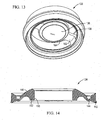
FIGURE 13 is an isometric view of a component of the embodiment of the present valve assembly shown inFIGURES 11 and12 ; -
FIGURE 14 is a cross-sectional view of a valve member of the valve assembly of the embodiment of the present valve assembly shown inFIGURES 11 and12 ; -
FIGURE 15 is an exploded, isometric view of a further embodiment of the present valve assembly; -
FIGURE 16 is an isometric view of the assembled valve assembly of this embodiment; -
FIGURE 17 is a cross-sectional view of the valve assembly of this embodiment shown in a closed configuration; and -
FIGURE 18 is a cross-sectional view, similar toFigure 17 , showing the valve assembly of this embodiment in an open condition. - While this invention is susceptible of embodiment in many different forms, this specification and the accompanying drawings disclose specific forms as examples of the invention. The invention is not intended to be limited to the embodiments so described, however. The scope of the invention is pointed out in the appended claims.
- For case of description, many of the figures showing the valve assembly of the present invention illustrate the assembly in a typical orientation in which it may be used, with terms such as upper, lower, horizontal, etc., used with reference to the illustrated positions. It will be understood, however, that the valve assembly of the present invention may be manufactured, stored, transported, and sold in an orientation other than the orientation described.
- The valve assembly of the present invention is suitable for use with a variety of conventional and special fluid flow systems, including containers, tanks, vessels, and other equipment or apparatus, the details of which, although not fully illustrated or described, would be apparent to those having skill in the art in an understanding of such fluid handling systems. It will be understood by those of ordinary skill in the art that novel and non-obvious inventive aspects are embodied in the described valve assembly alone.
- With reference to
FIGURES 1-10 , therein is illustrated a first embodiment of the present valve assembly, designated 20. This embodiment of the present valve assembly is configured as a so-called T-fitting, which is typically employed for pressure responsive introduction of a liquid into another liquid stream, via the T-fitting. This specifically illustrated embodiment can be advantageously employed in medical applications, such as infusion systems. - In this embodiment, the
valve assembly 20 includes a valve body which comprises avalve housing 24, and avalve retention member 26 joined by snap-fitment to the housing, with a flexibly resilient,elastomeric valve member 28 positioned within the valve body generally between the valve housing and the valve retention member, as will be further described. For a specific application in an infusion system, the illustrated embodiment of the present valve assembly includes a luer fitting 30, which can be threadably joined to thevalve housing 24 to facilitate attachment of tubing or other components to the valve assembly. - As will be further described, the present valve assembly has been particularly configured to function as a check valve to provide pressure-responsive flow through the assembly, while at the same time minimizing and substantially preventing reverse fluid flow. To this end, the
valve member 28 of the valve assembly cooperates with a valve seat defined by thevalve housing 24 of the valve body, which valve seat preferably includes a compound sealing surface, including first and second sealing surfaces, with a further preferred provision of at least one retention projection on one of the valve body and the valve member. These features of the present invention will now be described in connection with this first embodiment of the present valve assembly. - As illustrated, the
valve housing 24 of the valve body has a generally tubular configuration, and defines a firstinternal flow passage 32, which is joined in fluid communication with a second internalfluid flow passage 34 further defined by the valve housing of the valve body. The first and second internal flow passages of the valve housing are generally separated from each other by aninternal valve seat 36 of the valve body, which in this embodiment is provided by thevalve housing 24. - Fluid flow communication between the first and second internal flow passages of the valve housing is provided by at least one
flow port 38 defined by thevalve seat 36. In the illustrated embodiment, thevalve seat 36 of the valve housing defines a plurality of circumferentially spaced ones of theflow ports 38, which in this embodiment are circumferentially spaced about an axis defined by the first and second internal flow passages. By the provision of theflow ports 38, fluid flow communication is provided between the first and second internal flow passages across thevalve seat 36. - As noted, the
elastomeric valve member 28 cooperates with thevalve seat 36 to control fluid flow through the valve assembly in response to a pressure differential created across the valve assembly. To this end, the valve member has a generally annular configuration, and includes an annular,peripheral attachment portion 42 by which thevalve member 28 is attached to the valve body of thevalve assembly 20. The valve member further includes a flexible, resilient,intermediate portion 44 extending from theperipheral attachment portion 42. - The
valve member 28 includes avalve head 46, defining acentral flow orifice 50, with the valve head extending from theintermediate portion 44 for sealing engagement with thevalve seat 36 of the valve assembly. Pressure-responsive flow through the valve assembly from the firstinternal flow passage 32 to the secondinternal flow passage 34 is effected by at least a part of thevalve head 46 being outwardly deflectable to an open configuration of the valve member when a sufficient pressure differential exists across the valve assembly, to thereby permit flow from the first internal flow passage, throughflow port 38, and thecentral flow orifice 50 of the valve head to the secondinternal flow passage 34. - In the illustrated embodiment, the
valve head 46 of thevalve member 28 includes acentral sleeve portion 52 which defines the central flow orifice, with the sleeve portion extending generally away from thevalve seat 36. - In this embodiment of the present invention, outward deflection of the
valve head 46 of thevalve member 28 is limited by the provision of at least one stop member on the valve body of the valve assembly. In the illustrated embodiment, a plurality ofstop members 54 are provided onvalve retention member 26, with thestop members 54 spaced circumferentially about an axis defined by the secondinternal flow passage 34 of the valve body. - In this embodiment, the present valve assembly is configured as a so-called T-fitting, and to this end, the
valve retention member 26 defines aflow conduit 56 joined in fluid communication with the secondinternal flow passage 34 via a conduit opening 58 defined by thevalve retention member 26. In accordance with this embodiment, at least one stop member is positioned on each side of the conduit opening 58, with three such stop members positioned on each side of the conduit opening in the illustrated embodiment. - While the illustrated embodiment shows the
flow conduit 56 defined by thevalve retention member 26 as being disposed at a right angle to the first and second internal flow passages, it will be appreciated that such a T-fitting can be otherwise configured, for example, with theflow conduit 56 arranged at an acute angle to the internal flow passages of the valve assembly, or in other configurations while keeping with the principals of the present invention. - In accordance with the present invention, enhanced sealing engagement between the
valve member 28 and thevalve seat 36 of thevalve housing 24 is provided by configuring the valve seat to define a compound sealing surface, in particular, including afirst sealing surface 62, and asecond sealing surface 64, positioned inwardly of thefirst sealing surface 62. As will be observed, thefirst sealing surface 62, through which flowports 38 extend, has a generally arcuate cross-sectional configuration. In contrast, thesecond sealing surface 64 has a frusto-conical configuration, having a generally linear cross-sectional configuration. It is believed that this preferred configuration of the valve seat enhances resistance to reverse fluid flow through the valve assembly. - Enhanced sealing between the
valve member 28 and the valve housing is preferably further effected by the provision of at least one retention projection, on one of the valve body and the valve member, positioned generally intermediate the first and second sealing surfaces 62, 64, with the retention projection being engageable with the other of the valve body and the valve member. In the illustrated embodiment, anannular retention projection 66 is provided on thevalve housing 24 of the valve body, intermediate first and second sealing surfaces 62, 64, with theprojection 66 being engageable withvalve member 24 generally atvalve head 46. - Pressure-responsive operation of the
valve assembly 20 will be readily appreciated from the above description. When a sufficient pressure differential exists across thevalve housing 24 from firstinternal flow passage 32 to secondinternal flow passage 34, pressure acting throughflow port 38 against the valve member acts to deflect thevalve head 46 of the valve member out of sealing engagement with the valve seat, thus permitting fluid flow from the first internal flow passage, through the valve port, through central flow oforifice 50 of the valve member, and into the second internal flow passage. Outward deflection of the valve member is limited by thestop members 54 of the valve retention member, with this embodiment providing fluid flow from within the valve housing into theflow conduit 56 of the valve retention member. - The
valve head 46 ofvalve member 28 moves back into its closed configuration, in sealing engagement with thevalve seat 36, when there is an insufficient pressure differential between the firstinternal flow passage 32 and the secondinternal flow passage 34 to resist the resilience of the valve member. In its closed configuration,valve head 46 principally engages first sealingsurface 62, and can further engagesecond sealing surface 64 of the valve seat, with theretention projection 66 engaging and penetrating thevalve head 46. This cooperation between the valve head and the valve seat desirably acts to prevent reverse fluid flow through the valve assembly, with these preferred features of the present invention desirably enhancing resistance to reverse fluid flow. - Thus, this embodiment of the present invention provides a highly effective and economical check valve arrangement which can be advantageously employed such as for medical applications.
- With reference now to
FIGURES 11-14 , therein is illustrated an alternate embodiment of the valve assembly of the present invention, in which elements which generally correspond to the previous embodiment are designed by like reference numerals in the 100-series. - This embodiment of the valve assembly, designated 120, is like the previous embodiment in that it provides a pressure-responsive flow control arrangement, which permits fluid flow through the valve assembly when a predetermined pressure differential exists across the assembly, with the valve assembly substantially preventing reverse fluid flow therethrough.
- The
valve assembly 120 includes a valve body including avalve housing 124 having a generally tubular configuration, and an associatedvalve retention member 126, joined by snap-fitment to the housing, and which cooperates withvalve housing 124 to hold a flexible, resilientlydeformable valve member 128 in captive relationship between the valve housing and the retention member. In this embodiment, thevalve housing 124 of the valve body includes an internal thread formation at a threadedportion 130 of the housing, which can be configured for removable, threaded fitment to an associated container or like structure, thus facilitating dispensing of fluid from within the container through the valve assembly. - The
valve assembly 120 defines a firstinternal flow passage 132, provided upstream ofvalve member 128, and a secondinternal flow passage 134 disposed downstream of the valve member. Thevalve housing 124 of the valve body defines avalve seat 136, with the housing defining at least oneflow port 138 which provides fluid flow communication between the first and secondinternal flow passages - In distinction from the previous embodiment,
valve assembly 120 of the present invention includes avalve seat 136 which is defined byretention member 126 of the valve body. Theretention member 126 of the valve body defines at least oneflow port 138 which extends between the first and secondinternal flow passages - The flexible, resiliently
deformable valve member 128 of thevalve assembly 120 includes an annular,peripheral attachment portion 142 having a dovetail cross-sectional configuration by which the valve member is held in captive relationship between thevalve housing 124 and thevalve retention member 126. Thevalve member 128 further includes a flexible, resilient,intermediate portion 144 extending from theperipheral attachment portion 142, and acentral valve head 146 defining acentral flow orifice 150. Thevalve member 128 further includes asleeve portion 152 which defines thecentral flow orifice 150 through which fluid flows from the firstinternal passageway 132, through the one ormore valve portions 138, and into the second internalfluid flow passage 134. - As in the previous embodiment, this embodiment of the present valve assembly includes a valve seat which defines a compound sealing surface, including a first
outer sealing surface 162, and aninner sealing surface 164. As in the previous embodiment, thefirst sealing surface 162 has a generally arcuate cross-sectional configuration, with the one ormore flow ports 138 extending therethrough. In contrast, thesecond sealing surface 164 has a frusto-conical configuration, having a generally linear cross-sectional configuration. Again, enhanced resistance to reverse fluid flow is provided by the preferred compound configuration of the sealing surface atvalve seat 136. Fluid flow is provided when a sufficient pressure differential exists across the valve assembly from firstinternal flow passage 132 to secondinternal flow passage 134, thereby deflecting the head ofvalve 128 from its closed configuration in sealing engagement with the valve seat 136 (FIGURE 11 ), to its open configuration, wherein the valve head is deflected from the valve seat (FIGURE 12 ). - In this embodiment, a portion of the
valve housing 124, downstream ofvalve member 128, defines anannular groove 167 for retention of an associated elastomeric O-ring seal 169 to permit sealed engagement of the valve housing generally within an associated tubular structure, as may be desired for certain applications. - With reference now to
FIGURES 15-18 , therein is illustrated a further alternate embodiment of the valve assembly of the present invention, designated 220, with elements of this embodiment, which generally correspond to those of the previous embodiments designated by like reference numerals in the 200-series. -
Valve assembly 220 is provided generally in the form of a check valve assembly for fitment with associated tubing, conduits, containers, or the like for providing pressure-responsive flow control as may be required for any specific applications. As in the previous embodiments, flow through the valve assembly is provided when a sufficient pressure differential is created across the assembly. - In this embodiment, the valve assembly includes a valve body having a
valve housing 224 having a generally tubular configuration, and an associatedvalve retention member 226 which cooperates, by snap-fitment, with thevalve housing 224 to retain a generally annular, flexible, resilientlydeformable valve member 228 in captive relationship therebetween. - The valve body of
valve assembly 220 defines a firstinternal flow passage 232, and a secondinternal flow passage 234 which are respectively provided upstream and downstream of avalve seat 236 defined by the valve body, which in this embodiment is provided byvalve retention member 226. One ormore flow ports 238 extend between the first and second internal flow passages, joining the flow passages in fluid flow communication with each other. - A flexible, resiliently
deformable valve member 228 has a generally annular configuration, including an annularperipheral attachment portion 242 having a dovetail cross-sectional configuration for retention betweenvalve housing 224 andvalve retention member 226. The valve member further includes a flexible, resilient, intermediate portion 244 extending fromperipheral portion 242, and acentral valve head 246 which defines acentral flow orifice 250. In the illustrated embodiment, thevalve head 246 of the valve member includes asleeve portion 252 which defines thecentral flow orifice 250, and extends generally away from the valve seat. - In accordance with the present invention, the
valve seat 236 of thevalve assembly 220 has a compound sealing surface, including a first,outer sealing surface 262, and a second,inner sealing surface 264. As in the previous embodiments, first sealingsurface 262, through which flowports 238 extend, has a generally arcuate, cross-sectional configuration. In contrast,second sealing surface 264 has a frusto-conical configuration, with a generally linear cross-sectional configuration. Enhanced resistance to reverse fluid flow is provided. - In the illustrated embodiment, the valve assembly includes an elastomeric sealing O-
ring 267 fitted about the exterior ofvalve housing 224 for sealed fitment of the valve assembly within an associated tubular structure or like arrangement. - Pressure-responsive fluid flow control is provided by deflection of the
central valve head 246 away from the associated valve seat from a closed configuration (FIGURE 17 ) to an open configuration (FIGURE 18 ) when a sufficient pressure differential exists across the valve assembly to thus permit flow from the firstinternal flow passage 232, throughflow ports 238 andcentral orifice 250, to secondinternal flow passage 234. - It will be readily observed from the foregoing detailed description of the invention and from the illustrations thereof that numerous other variations and modifications can be effected without departing from the scope of this invention, as defined by the claims.
Claims (14)
- A valve assembly (20, 120, 220) for controlling flow of a fluid within the assembly, said valve assembly (20, 120, 220) comprising:a valve body (24, 124, 224) defining first and second internal flow passages (32, 34; 132, 134; 232, 234), said valve body (24, 124, 224) including an internal valve seat (36, 136, 236) positioned between said first and second internal flow passages (32, 34; 132, 134; 232, 234), said valve seat (36, 136, 236) defining at least one flow port (38, 138, 238) extending between said first and second flow passages (32, 34; 132, 134; 232, 234) for joining said flow passages (32, 34; 132, 134; 232, 234) in fluid communication with each other; anda flow-controlling valve member (28, 128, 228) positioned within said valve body (24, 124, 224) generally adjacent to said valve seat (36, 136, 236) for controlling flow between said first and second flow passages (32, 34; 132, 134; 232, 234) through said flow port (38,138,238),said valve member (28, 128, 228) including a peripheral attachment portion (42, 142, 242) by which said valve member (28, 128, 228) can be attached to said valve body (24, 124, 224), a flexible, resilient, intermediate portion (44, 144) extending from said peripheral attachment portion (42, 142, 242), and a central valve head (46, 146, 246), defining a central flow orifice (50, 150, 250), extending from said intermediate portion (44, 144) for sealing engagement with said valve seat (36, 136, 236) of said valve body (24, 124, 224), at least part of said valve head (46, 146, 246) being outwardly deflectable to an open configuration of said valve member (28, 128, 228) when a sufficient pressure differential exists across said valve assembly (20, 120, 22) to permit flow from said first internal flow passage (32, 132, 232) through said flow port (38, 138, 238) and said central flow orifice (50, 150, 250) to said second internal flow passage (34, 134, 234),said valve seat (36, 136, 236) defining a compound sealing surface (62, 64; 162, 164; 262, 264) for cooperative sealing engagement with the valve head (46, 146, 246) of said valve member (28, 128, 228), said compound sealing surface (62, 64; 162, 164; 262, 264) including a first sealing surface (62, 162, 262) through which said at least one flow port (38, 138, 238) extends, and a second, frusto-conical sealing surface (64, 164, 264), positioned inwardly of said first sealing surface (62, 162, 262), having a generally linear cross-sectional configuration, said valve head (46, 146, 246) being sealingly engagable with said first and second sealing surfaces (62, 64; 162, 164; 262, 264) in a closed configuration of said valve member (28, 128, 228) for preventing flow from said second internal flow passage (34, 134, 234) through said flow port (38, 138, 238) to said first internal flow passage (32, 132, 232), characterised in that the first sealing surface (62, 162, 262) has a generally arcuate cross-sectional configuration and in that the first sealing surface (62, 162, 262) extends radially inwards towards the first internal flow passage (32, 132, 232) and the second sealing surface (64, 164, 264) extends radially inwards towards the second internal flow passage (34, 134, 234).
- The valve assembly (20) in accordance with claim 1, wherein one of said valve body (24) and said valve member (28) defines at least one retention projection (66), positioned generally intermediate said first and second sealing surfaces (62, 64), and engageable with the other of said valve body (24) and said valve member (28).
- The valve assembly (20) in accordance with claim 1, wherein said valve body (24) defines at least one stop member (54) for limiting deflection of the valve head (46) of said valve member (28) in the open configuration thereof.
- The valve assembly (20) in accordance with claim 3, wherein said valve body (24) defines a plurality of said stop members (54) spaced circumferentially about an axis defined by said second internal flow passage (34) of said valve body (24).
- The valve assembly (20, 120, 220) in accordance with claim 1, wherein said valve head (46, 146, 246) of said valve member (28, 128, 228) includes a central sleeve portion (52, 152, 252) that defines said central flow orifice (50, 150, 250), said sleeve portion (52, 152, 252) extending generally away from said second sealing surface (64, 164, 264) of said valve seat (36, 136, 236).
- A valve assembly (20) in accordance with claim 1, wherein said valve body (24) defines at least one retention projection (66) positioned generally intermediate said first and second sealing surfaces (62, 64), said retention projection (66) being engagable with said valve head (46) of said valve member (28) when said valve head (46) sealingly engages said first and second sealing surfaces (62, 64).
- A valve assembly (20) in accordance with claim 6, wherein said retention projection (66) has an annular configuration.
- A valve assembly (20) in accordance with claim 7, wherein said retention projection (66) is continuous.
- A valve assembly (20, 120, 220) in accordance with claim 1, wherein said peripheral attachment portion (42, 142, 242) of said valve member (28, 128, 228) has a dove-tail cross-sectional configuration.
- A valve assembly (20, 120, 220) in accordance with claim 1, wherein said valve body (24, 124, 224) includes a valve housing (24, 124, 224) which defines said valve seat (36, 136, 236), and a valve retention member (26, 126, 226) having an annular valve retention portion, said valve member (28, 128, 228) being positoned in captive relationship between said valve housing (24, 124, 224) and said annular retention portion of said valve retention member (26, 126, 226).
- A valve assembly (20) in accordance with claim 10, wherein said valve retention member (26) defines a flow conduit (56) joined in fluid communication with said second internal flow passage (34) via a conduit opening (58) defined by said valve retention member (26).
- A valve assembly (20) in accordance with claim 11, wherein said valve retention member (26) includes at least one stop member (54) positioned on each side of said conduit opening (58) for limiting deflection of the valve head (46) of said valve member (28) in the open configuration thereof.
- A valve assembly (20) in accordance with claim 11, wherein said flow conduit (56) defined by said valve retention member (26) is disposed at a right angle to said first and second internal flow passages (32, 34).
- A valve assembly (20) in accordance with claim 1, wherein said valve body includes an internal thread formation (30) at said first internal flow passage (32).
Priority Applications (1)
| Application Number | Priority Date | Filing Date | Title |
|---|---|---|---|
| PL09730331T PL2260222T3 (en) | 2008-04-09 | 2009-02-12 | Valve assembly |
Applications Claiming Priority (2)
| Application Number | Priority Date | Filing Date | Title |
|---|---|---|---|
| US12/082,125 US8079385B2 (en) | 2008-04-09 | 2008-04-09 | Valve assembly |
| PCT/US2009/000899 WO2009126193A1 (en) | 2008-04-09 | 2009-02-12 | Valve assembly |
Publications (3)
| Publication Number | Publication Date |
|---|---|
| EP2260222A1 EP2260222A1 (en) | 2010-12-15 |
| EP2260222A4 EP2260222A4 (en) | 2013-08-14 |
| EP2260222B1 true EP2260222B1 (en) | 2015-06-03 |
Family
ID=41162151
Family Applications (1)
| Application Number | Title | Priority Date | Filing Date |
|---|---|---|---|
| EP09730331.7A Not-in-force EP2260222B1 (en) | 2008-04-09 | 2009-02-12 | Valve assembly |
Country Status (11)
| Country | Link |
|---|---|
| US (2) | US8079385B2 (en) |
| EP (1) | EP2260222B1 (en) |
| CN (2) | CN102563139B (en) |
| AR (1) | AR071188A1 (en) |
| AU (1) | AU2009234449A1 (en) |
| BR (1) | BRPI0911175A8 (en) |
| CA (1) | CA2716668C (en) |
| MX (1) | MX2010009125A (en) |
| PL (1) | PL2260222T3 (en) |
| RU (1) | RU2482368C2 (en) |
| WO (1) | WO2009126193A1 (en) |
Families Citing this family (38)
| Publication number | Priority date | Publication date | Assignee | Title |
|---|---|---|---|---|
| US7648085B2 (en) | 2006-02-22 | 2010-01-19 | Rain Bird Corporation | Drip emitter |
| US8079385B2 (en) * | 2008-04-09 | 2011-12-20 | Liquid Molding Systems, Inc. | Valve assembly |
| US8439282B2 (en) | 2009-02-06 | 2013-05-14 | Rain Bird Corporation | Low flow irrigation emitter |
| US8602236B2 (en) * | 2011-11-04 | 2013-12-10 | RNR IP Holdings, LLC | Bottle including a base portion and a hollow closure for removably sealing the base portion |
| US8714201B2 (en) * | 2012-02-07 | 2014-05-06 | Water Boger Hardware (Shenzhen) Co., Ltd. | Water-saving device structure |
| US10440903B2 (en) | 2012-03-26 | 2019-10-15 | Rain Bird Corporation | Drip line emitter and methods relating to same |
| US9485923B2 (en) | 2012-03-26 | 2016-11-08 | Rain Bird Corporation | Elastomeric emitter and methods relating to same |
| US20130248622A1 (en) | 2012-03-26 | 2013-09-26 | Jae Yung Kim | Drip line and emitter and methods relating to same |
| US9877440B2 (en) | 2012-03-26 | 2018-01-30 | Rain Bird Corporation | Elastomeric emitter and methods relating to same |
| USD700289S1 (en) * | 2012-08-10 | 2014-02-25 | William Edmund Cooke | Propane valve protective device |
| US8640733B1 (en) * | 2012-10-09 | 2014-02-04 | Brasscraft Manufacturing Company | Excess flow cartridge |
| US9060592B2 (en) | 2012-11-28 | 2015-06-23 | Specialized Bicycle Components, Inc. | Water bottle with poppet valve |
| CN103062448B (en) * | 2012-12-29 | 2014-01-08 | 浙江盾安阀门有限公司 | Anti-leaking check valve |
| US20140261799A1 (en) * | 2013-03-14 | 2014-09-18 | Gojo Industries, Inc. | Simplified liquid outlet valves, pumps and refill units |
| US9872444B2 (en) | 2013-03-15 | 2018-01-23 | Rain Bird Corporation | Drip emitter |
| CN103244709B (en) * | 2013-05-06 | 2017-08-25 | 重庆长安汽车股份有限公司 | Pressure-regulating valve |
| PL222826B1 (en) * | 2013-07-18 | 2016-09-30 | Ajh047 Spółka Z Ograniczoną Odpowiedzialnością | Container inlet / outlet channel valve |
| US10631473B2 (en) | 2013-08-12 | 2020-04-28 | Rain Bird Corporation | Elastomeric emitter and methods relating to same |
| USD811179S1 (en) | 2013-08-12 | 2018-02-27 | Rain Bird Corporation | Emitter part |
| US10285342B2 (en) | 2013-08-12 | 2019-05-14 | Rain Bird Corporation | Elastomeric emitter and methods relating to same |
| US9883640B2 (en) | 2013-10-22 | 2018-02-06 | Rain Bird Corporation | Methods and apparatus for transporting elastomeric emitters and/or manufacturing drip lines |
| EP3099594A4 (en) | 2014-01-31 | 2018-01-24 | Specialized Bicycle Components, Inc. | Water bottle with self-closing valve |
| CA2959755A1 (en) | 2014-09-05 | 2016-03-10 | Jeff Cox | Receptacle closure |
| US10330559B2 (en) | 2014-09-11 | 2019-06-25 | Rain Bird Corporation | Methods and apparatus for checking emitter bonds in an irrigation drip line |
| US10258191B2 (en) * | 2015-09-18 | 2019-04-16 | Starbucks Corporation | Beverage dispensing systems and methods |
| KR102692528B1 (en) * | 2015-10-01 | 2024-08-06 | 리플리겐 코포레이션 | Valve assembly with directional flow path |
| PL3368143T3 (en) | 2015-10-30 | 2021-05-17 | Aptargroup, Inc. | Flow control device |
| JP6689634B2 (en) * | 2016-03-17 | 2020-04-28 | 株式会社エンプラス | Emitter and drip irrigation tubes |
| TWI608188B (en) * | 2016-07-18 | 2017-12-11 | Chen Bao Tang | Water flow limiter |
| US10375904B2 (en) | 2016-07-18 | 2019-08-13 | Rain Bird Corporation | Emitter locating system and related methods |
| US11051466B2 (en) | 2017-01-27 | 2021-07-06 | Rain Bird Corporation | Pressure compensation members, emitters, drip line and methods relating to same |
| US10626998B2 (en) | 2017-05-15 | 2020-04-21 | Rain Bird Corporation | Drip emitter with check valve |
| US10836541B2 (en) | 2017-11-27 | 2020-11-17 | Gateway Plastics, Inc. | Valve for a dispensing container |
| USD883048S1 (en) | 2017-12-12 | 2020-05-05 | Rain Bird Corporation | Emitter part |
| US11985924B2 (en) | 2018-06-11 | 2024-05-21 | Rain Bird Corporation | Emitter outlet, emitter, drip line and methods relating to same |
| KR102714476B1 (en) * | 2019-10-11 | 2024-10-07 | 현대자동차주식회사 | Valve assembly and seal member applied to the valve assembly |
| US12207599B2 (en) | 2021-10-12 | 2025-01-28 | Rain Bird Corporation | Emitter coupler and irrigation system |
| US12523328B2 (en) * | 2024-04-12 | 2026-01-13 | Ketterling Kody J | Valved coupling for drip irrigation line |
Family Cites Families (36)
| Publication number | Priority date | Publication date | Assignee | Title |
|---|---|---|---|---|
| US2497906A (en) * | 1944-10-20 | 1950-02-21 | Peters & Russell Inc | Valved hose connection |
| US2605957A (en) * | 1945-06-20 | 1952-08-05 | Junius W Houston | Pumping apparatus |
| US2646063A (en) * | 1949-11-15 | 1953-07-21 | Stanley A Hayes | Back flow preventer |
| GB860026A (en) | 1956-10-18 | 1961-02-01 | Renault | Improvements in and relating to resilient valves for fluids under pressure |
| US3221952A (en) * | 1963-11-27 | 1965-12-07 | Halkey Roberts Corp | Dispensing container closure |
| US3321114A (en) * | 1966-03-04 | 1967-05-23 | Rexall Drug Chemical | Pop-up diaphragm closure |
| US3804113A (en) * | 1971-06-21 | 1974-04-16 | Alfa Romeo Spa | Automatic non-return valve |
| SU433314A1 (en) * | 1973-02-09 | 1974-06-25 | DIAFRAGMENT CHECK VALVE | |
| US4570826A (en) * | 1983-03-31 | 1986-02-18 | The Rel Corporation | Dispenser closure |
| GB8413826D0 (en) * | 1984-05-31 | 1984-07-04 | Cartwright G E | Pumps |
| US4646945A (en) * | 1985-06-28 | 1987-03-03 | Steiner Company, Inc. | Vented discharge assembly for liquid soap dispenser |
| US4874369A (en) * | 1987-07-27 | 1989-10-17 | Baxter International Inc. | Self-priming injection site with check valve |
| DE68927896T2 (en) * | 1988-01-25 | 1997-10-23 | Baxter Int | Pre-slit injection site and injection cannula |
| US5033655A (en) * | 1989-02-15 | 1991-07-23 | Liquid Molding Systems Inc. | Dispensing package for fluid products and the like |
| US5115950A (en) * | 1991-01-14 | 1992-05-26 | Seaquist Closures A Divison Of Pittway Corporation | Dispensing closure with unitary structure for retaining a pressure-actuated flexible valve |
| US5271571A (en) * | 1991-02-19 | 1993-12-21 | Maynard Jr Stuart T | Water driven device for agitating and fragmenting debris in a sink drain |
| US5839614A (en) * | 1991-12-06 | 1998-11-24 | Aptar Group, Inc. | Dispensing package |
| US5213236A (en) * | 1991-12-06 | 1993-05-25 | Liquid Molding Systems, Inc. | Dispensing valve for packaging |
| US5409144A (en) * | 1991-12-06 | 1995-04-25 | Liquid Molding Systems Inc. | Dispensing valve for packaging |
| US5242423A (en) * | 1992-03-09 | 1993-09-07 | American Home Products Corporation | Needleless syringe |
| US5531363A (en) * | 1994-06-10 | 1996-07-02 | Aptargroup, Inc. | Dispensing closure cartridge valve system |
| CN1079355C (en) * | 1995-09-05 | 2002-02-20 | 策拉塑料有限公司 | Self-closing seal and sealing film |
| US5788215A (en) * | 1995-12-29 | 1998-08-04 | Rymed Technologies | Medical intravenous administration line connectors having a luer or pressure activated valve |
| US5954313A (en) * | 1995-12-29 | 1999-09-21 | Rymed Technologies, Inc. | Medical intravenous administration line connectors having a luer activated valve |
| GB9717595D0 (en) * | 1997-08-21 | 1997-10-22 | Metal Box Plc | Valves for packaging containers |
| US6062438A (en) * | 1998-04-20 | 2000-05-16 | Mars, Inc. | Apparatus for dispensing of bulk product |
| US6065642A (en) * | 1998-12-09 | 2000-05-23 | Aptargroup, Inc. | Non-venting valve and dispensing package for fluid products and the like |
| US6062435A (en) | 1999-05-06 | 2000-05-16 | Aptargroup, Inc. | Valved dispensing system with priming liquid loss prevention |
| US6616012B2 (en) * | 2001-07-27 | 2003-09-09 | Richard C. G. Dark | Fluid dispensing valve and method of use |
| US6749092B2 (en) * | 2001-08-10 | 2004-06-15 | Seaquist Closures Foreign, Inc. | Deformable dispensing valve |
| CN1300266C (en) | 2002-02-08 | 2007-02-14 | 富士胶片株式会社 | Inkjet recording ink, ink set for inkjet recording, and inkjet recording method |
| US6951295B1 (en) * | 2005-01-18 | 2005-10-04 | Seaquist Closures Foreign, Inc. | Flow control element and dispensing structure incorporating same |
| FR2895687B1 (en) * | 2006-01-02 | 2008-07-04 | Lvmh Rech | FLUID PRODUCT DISTRIBUTION NOZZLE, DISTRIBUTION DEVICE COMPRISING SUCH A NOZZLE, AND METHOD OF MANUFACTURING |
| DE202006012645U1 (en) * | 2006-08-17 | 2006-11-16 | Filtertek B.V. | Check valve e.g. for gas lines, is rotationally symmetric and has valve seat containing center section, inlet channel and outlet channel with flexible seal covering outlet channel forming valve closing member |
| MX354654B (en) * | 2006-08-28 | 2018-03-14 | Liqui Box Canada Inc | Slider valve fitment and collar. |
| US8079385B2 (en) * | 2008-04-09 | 2011-12-20 | Liquid Molding Systems, Inc. | Valve assembly |
-
2008
- 2008-04-09 US US12/082,125 patent/US8079385B2/en active Active
-
2009
- 2009-02-12 PL PL09730331T patent/PL2260222T3/en unknown
- 2009-02-12 CA CA2716668A patent/CA2716668C/en not_active Expired - Fee Related
- 2009-02-12 WO PCT/US2009/000899 patent/WO2009126193A1/en not_active Ceased
- 2009-02-12 RU RU2010145400/06A patent/RU2482368C2/en not_active IP Right Cessation
- 2009-02-12 EP EP09730331.7A patent/EP2260222B1/en not_active Not-in-force
- 2009-02-12 CN CN201210032264.6A patent/CN102563139B/en not_active Expired - Fee Related
- 2009-02-12 MX MX2010009125A patent/MX2010009125A/en active IP Right Grant
- 2009-02-12 BR BRPI0911175A patent/BRPI0911175A8/en not_active Application Discontinuation
- 2009-02-12 AU AU2009234449A patent/AU2009234449A1/en not_active Abandoned
- 2009-02-12 CN CN2009801126019A patent/CN101990611B/en not_active Expired - Fee Related
- 2009-04-07 AR ARP090101239 patent/AR071188A1/en not_active Application Discontinuation
-
2011
- 2011-11-21 US US13/301,052 patent/US8196608B2/en active Active
Also Published As
| Publication number | Publication date |
|---|---|
| PL2260222T3 (en) | 2015-11-30 |
| EP2260222A1 (en) | 2010-12-15 |
| EP2260222A4 (en) | 2013-08-14 |
| AU2009234449A1 (en) | 2009-10-15 |
| US8079385B2 (en) | 2011-12-20 |
| RU2482368C2 (en) | 2013-05-20 |
| CA2716668A1 (en) | 2009-10-15 |
| CN101990611A (en) | 2011-03-23 |
| BRPI0911175A8 (en) | 2019-01-08 |
| RU2010145400A (en) | 2012-05-20 |
| US8196608B2 (en) | 2012-06-12 |
| BRPI0911175A2 (en) | 2015-10-13 |
| CN101990611B (en) | 2013-11-06 |
| CN102563139B (en) | 2014-04-09 |
| WO2009126193A1 (en) | 2009-10-15 |
| US20120074345A1 (en) | 2012-03-29 |
| MX2010009125A (en) | 2010-09-10 |
| CN102563139A (en) | 2012-07-11 |
| AR071188A1 (en) | 2010-06-02 |
| CA2716668C (en) | 2016-04-19 |
| US20090256101A1 (en) | 2009-10-15 |
Similar Documents
| Publication | Publication Date | Title |
|---|---|---|
| CA2716668C (en) | Valve assembly | |
| US20230226503A1 (en) | Adjustable additive delivery systems and dispensing closure valves for the same | |
| EP2822699B1 (en) | Spray gun having internal boost passageway | |
| US4730635A (en) | Valve and method | |
| US5862961A (en) | Connection device for dispensing fluid from a bottle | |
| US5072756A (en) | Valve assembly for fluid line connection | |
| AU2019332947B2 (en) | Adjustable additive delivery systems and dispensing closure valves for the same | |
| AU672452B2 (en) | Fluid couplings | |
| EP2696115B1 (en) | Three-position valve for water supply systems | |
| CA1130161A (en) | Drip chamber with backflow ball valve | |
| WO1994001706A1 (en) | Valve assembly with backflow prevention and atmospheric vacuum breaker devices | |
| CA2630967C (en) | Connector/device with reflux valves | |
| US11534705B2 (en) | Filter assembly | |
| HK40113274A (en) | Adjustable additive delivery systems and dispensing closure valves for the same | |
| AU2012200810B2 (en) | Dome Check Valve | |
| HK40045680B (en) | Adjustable additive delivery systems and dispensing closure valves for the same | |
| AU4547793A (en) | Valve assembly with backflow prevention and atmospheric vacuum breaker devices | |
| JPH0324376A (en) | Proportional control valve |
Legal Events
| Date | Code | Title | Description |
|---|---|---|---|
| PUAI | Public reference made under article 153(3) epc to a published international application that has entered the european phase |
Free format text: ORIGINAL CODE: 0009012 |
|
| 17P | Request for examination filed |
Effective date: 20100818 |
|
| AK | Designated contracting states |
Kind code of ref document: A1 Designated state(s): AT BE BG CH CY CZ DE DK EE ES FI FR GB GR HR HU IE IS IT LI LT LU LV MC MK MT NL NO PL PT RO SE SI SK TR |
|
| AX | Request for extension of the european patent |
Extension state: AL BA RS |
|
| DAX | Request for extension of the european patent (deleted) | ||
| RAP1 | Party data changed (applicant data changed or rights of an application transferred) |
Owner name: APTARGROUP, INC. |
|
| A4 | Supplementary search report drawn up and despatched |
Effective date: 20130715 |
|
| RIC1 | Information provided on ipc code assigned before grant |
Ipc: F16K 15/00 20060101AFI20130709BHEP |
|
| 17Q | First examination report despatched |
Effective date: 20140407 |
|
| GRAP | Despatch of communication of intention to grant a patent |
Free format text: ORIGINAL CODE: EPIDOSNIGR1 |
|
| INTG | Intention to grant announced |
Effective date: 20150127 |
|
| GRAS | Grant fee paid |
Free format text: ORIGINAL CODE: EPIDOSNIGR3 |
|
| GRAA | (expected) grant |
Free format text: ORIGINAL CODE: 0009210 |
|
| AK | Designated contracting states |
Kind code of ref document: B1 Designated state(s): AT BE BG CH CY CZ DE DK EE ES FI FR GB GR HR HU IE IS IT LI LT LU LV MC MK MT NL NO PL PT RO SE SI SK TR |
|
| REG | Reference to a national code |
Ref country code: GB Ref legal event code: FG4D |
|
| REG | Reference to a national code |
Ref country code: CH Ref legal event code: EP |
|
| REG | Reference to a national code |
Ref country code: AT Ref legal event code: REF Ref document number: 730095 Country of ref document: AT Kind code of ref document: T Effective date: 20150715 Ref country code: IE Ref legal event code: FG4D |
|
| REG | Reference to a national code |
Ref country code: DE Ref legal event code: R096 Ref document number: 602009031545 Country of ref document: DE |
|
| REG | Reference to a national code |
Ref country code: AT Ref legal event code: MK05 Ref document number: 730095 Country of ref document: AT Kind code of ref document: T Effective date: 20150603 |
|
| PG25 | Lapsed in a contracting state [announced via postgrant information from national office to epo] |
Ref country code: HR Free format text: LAPSE BECAUSE OF FAILURE TO SUBMIT A TRANSLATION OF THE DESCRIPTION OR TO PAY THE FEE WITHIN THE PRESCRIBED TIME-LIMIT Effective date: 20150603 Ref country code: FI Free format text: LAPSE BECAUSE OF FAILURE TO SUBMIT A TRANSLATION OF THE DESCRIPTION OR TO PAY THE FEE WITHIN THE PRESCRIBED TIME-LIMIT Effective date: 20150603 Ref country code: NO Free format text: LAPSE BECAUSE OF FAILURE TO SUBMIT A TRANSLATION OF THE DESCRIPTION OR TO PAY THE FEE WITHIN THE PRESCRIBED TIME-LIMIT Effective date: 20150903 Ref country code: LT Free format text: LAPSE BECAUSE OF FAILURE TO SUBMIT A TRANSLATION OF THE DESCRIPTION OR TO PAY THE FEE WITHIN THE PRESCRIBED TIME-LIMIT Effective date: 20150603 Ref country code: ES Free format text: LAPSE BECAUSE OF FAILURE TO SUBMIT A TRANSLATION OF THE DESCRIPTION OR TO PAY THE FEE WITHIN THE PRESCRIBED TIME-LIMIT Effective date: 20150603 |
|
| REG | Reference to a national code |
Ref country code: NL Ref legal event code: MP Effective date: 20150603 |
|
| REG | Reference to a national code |
Ref country code: LT Ref legal event code: MG4D |
|
| PG25 | Lapsed in a contracting state [announced via postgrant information from national office to epo] |
Ref country code: LV Free format text: LAPSE BECAUSE OF FAILURE TO SUBMIT A TRANSLATION OF THE DESCRIPTION OR TO PAY THE FEE WITHIN THE PRESCRIBED TIME-LIMIT Effective date: 20150603 Ref country code: AT Free format text: LAPSE BECAUSE OF FAILURE TO SUBMIT A TRANSLATION OF THE DESCRIPTION OR TO PAY THE FEE WITHIN THE PRESCRIBED TIME-LIMIT Effective date: 20150603 Ref country code: BG Free format text: LAPSE BECAUSE OF FAILURE TO SUBMIT A TRANSLATION OF THE DESCRIPTION OR TO PAY THE FEE WITHIN THE PRESCRIBED TIME-LIMIT Effective date: 20150903 Ref country code: GR Free format text: LAPSE BECAUSE OF FAILURE TO SUBMIT A TRANSLATION OF THE DESCRIPTION OR TO PAY THE FEE WITHIN THE PRESCRIBED TIME-LIMIT Effective date: 20150904 |
|
| REG | Reference to a national code |
Ref country code: PL Ref legal event code: T3 |
|
| PG25 | Lapsed in a contracting state [announced via postgrant information from national office to epo] |
Ref country code: EE Free format text: LAPSE BECAUSE OF FAILURE TO SUBMIT A TRANSLATION OF THE DESCRIPTION OR TO PAY THE FEE WITHIN THE PRESCRIBED TIME-LIMIT Effective date: 20150603 |
|
| REG | Reference to a national code |
Ref country code: FR Ref legal event code: PLFP Year of fee payment: 8 |
|
| PG25 | Lapsed in a contracting state [announced via postgrant information from national office to epo] |
Ref country code: RO Free format text: LAPSE BECAUSE OF NON-PAYMENT OF DUE FEES Effective date: 20150603 Ref country code: PT Free format text: LAPSE BECAUSE OF FAILURE TO SUBMIT A TRANSLATION OF THE DESCRIPTION OR TO PAY THE FEE WITHIN THE PRESCRIBED TIME-LIMIT Effective date: 20151006 Ref country code: CZ Free format text: LAPSE BECAUSE OF FAILURE TO SUBMIT A TRANSLATION OF THE DESCRIPTION OR TO PAY THE FEE WITHIN THE PRESCRIBED TIME-LIMIT Effective date: 20150603 Ref country code: SK Free format text: LAPSE BECAUSE OF FAILURE TO SUBMIT A TRANSLATION OF THE DESCRIPTION OR TO PAY THE FEE WITHIN THE PRESCRIBED TIME-LIMIT Effective date: 20150603 Ref country code: IS Free format text: LAPSE BECAUSE OF FAILURE TO SUBMIT A TRANSLATION OF THE DESCRIPTION OR TO PAY THE FEE WITHIN THE PRESCRIBED TIME-LIMIT Effective date: 20151003 |
|
| REG | Reference to a national code |
Ref country code: DE Ref legal event code: R097 Ref document number: 602009031545 Country of ref document: DE |
|
| PLBE | No opposition filed within time limit |
Free format text: ORIGINAL CODE: 0009261 |
|
| STAA | Information on the status of an ep patent application or granted ep patent |
Free format text: STATUS: NO OPPOSITION FILED WITHIN TIME LIMIT |
|
| PG25 | Lapsed in a contracting state [announced via postgrant information from national office to epo] |
Ref country code: IT Free format text: LAPSE BECAUSE OF FAILURE TO SUBMIT A TRANSLATION OF THE DESCRIPTION OR TO PAY THE FEE WITHIN THE PRESCRIBED TIME-LIMIT Effective date: 20150603 Ref country code: DK Free format text: LAPSE BECAUSE OF FAILURE TO SUBMIT A TRANSLATION OF THE DESCRIPTION OR TO PAY THE FEE WITHIN THE PRESCRIBED TIME-LIMIT Effective date: 20150603 |
|
| 26N | No opposition filed |
Effective date: 20160304 |
|
| PG25 | Lapsed in a contracting state [announced via postgrant information from national office to epo] |
Ref country code: BE Free format text: LAPSE BECAUSE OF NON-PAYMENT OF DUE FEES Effective date: 20160229 Ref country code: SI Free format text: LAPSE BECAUSE OF FAILURE TO SUBMIT A TRANSLATION OF THE DESCRIPTION OR TO PAY THE FEE WITHIN THE PRESCRIBED TIME-LIMIT Effective date: 20150603 |
|
| PGFP | Annual fee paid to national office [announced via postgrant information from national office to epo] |
Ref country code: PL Payment date: 20160218 Year of fee payment: 8 |
|
| PG25 | Lapsed in a contracting state [announced via postgrant information from national office to epo] |
Ref country code: LU Free format text: LAPSE BECAUSE OF FAILURE TO SUBMIT A TRANSLATION OF THE DESCRIPTION OR TO PAY THE FEE WITHIN THE PRESCRIBED TIME-LIMIT Effective date: 20160212 Ref country code: MC Free format text: LAPSE BECAUSE OF FAILURE TO SUBMIT A TRANSLATION OF THE DESCRIPTION OR TO PAY THE FEE WITHIN THE PRESCRIBED TIME-LIMIT Effective date: 20150603 |
|
| REG | Reference to a national code |
Ref country code: CH Ref legal event code: PL |
|
| GBPC | Gb: european patent ceased through non-payment of renewal fee |
Effective date: 20160212 |
|
| PG25 | Lapsed in a contracting state [announced via postgrant information from national office to epo] |
Ref country code: LI Free format text: LAPSE BECAUSE OF NON-PAYMENT OF DUE FEES Effective date: 20160229 Ref country code: CH Free format text: LAPSE BECAUSE OF NON-PAYMENT OF DUE FEES Effective date: 20160229 |
|
| REG | Reference to a national code |
Ref country code: IE Ref legal event code: MM4A |
|
| PG25 | Lapsed in a contracting state [announced via postgrant information from national office to epo] |
Ref country code: BE Free format text: LAPSE BECAUSE OF FAILURE TO SUBMIT A TRANSLATION OF THE DESCRIPTION OR TO PAY THE FEE WITHIN THE PRESCRIBED TIME-LIMIT Effective date: 20150603 |
|
| PG25 | Lapsed in a contracting state [announced via postgrant information from national office to epo] |
Ref country code: GB Free format text: LAPSE BECAUSE OF NON-PAYMENT OF DUE FEES Effective date: 20160212 Ref country code: IE Free format text: LAPSE BECAUSE OF NON-PAYMENT OF DUE FEES Effective date: 20160212 |
|
| REG | Reference to a national code |
Ref country code: FR Ref legal event code: PLFP Year of fee payment: 9 |
|
| PG25 | Lapsed in a contracting state [announced via postgrant information from national office to epo] |
Ref country code: NL Free format text: LAPSE BECAUSE OF FAILURE TO SUBMIT A TRANSLATION OF THE DESCRIPTION OR TO PAY THE FEE WITHIN THE PRESCRIBED TIME-LIMIT Effective date: 20150603 Ref country code: SE Free format text: LAPSE BECAUSE OF FAILURE TO SUBMIT A TRANSLATION OF THE DESCRIPTION OR TO PAY THE FEE WITHIN THE PRESCRIBED TIME-LIMIT Effective date: 20150603 |
|
| PG25 | Lapsed in a contracting state [announced via postgrant information from national office to epo] |
Ref country code: MT Free format text: LAPSE BECAUSE OF FAILURE TO SUBMIT A TRANSLATION OF THE DESCRIPTION OR TO PAY THE FEE WITHIN THE PRESCRIBED TIME-LIMIT Effective date: 20150603 |
|
| REG | Reference to a national code |
Ref country code: FR Ref legal event code: PLFP Year of fee payment: 10 |
|
| PG25 | Lapsed in a contracting state [announced via postgrant information from national office to epo] |
Ref country code: HU Free format text: LAPSE BECAUSE OF FAILURE TO SUBMIT A TRANSLATION OF THE DESCRIPTION OR TO PAY THE FEE WITHIN THE PRESCRIBED TIME-LIMIT; INVALID AB INITIO Effective date: 20090212 Ref country code: CY Free format text: LAPSE BECAUSE OF FAILURE TO SUBMIT A TRANSLATION OF THE DESCRIPTION OR TO PAY THE FEE WITHIN THE PRESCRIBED TIME-LIMIT Effective date: 20150603 |
|
| PG25 | Lapsed in a contracting state [announced via postgrant information from national office to epo] |
Ref country code: MK Free format text: LAPSE BECAUSE OF FAILURE TO SUBMIT A TRANSLATION OF THE DESCRIPTION OR TO PAY THE FEE WITHIN THE PRESCRIBED TIME-LIMIT Effective date: 20150603 Ref country code: TR Free format text: LAPSE BECAUSE OF FAILURE TO SUBMIT A TRANSLATION OF THE DESCRIPTION OR TO PAY THE FEE WITHIN THE PRESCRIBED TIME-LIMIT Effective date: 20150603 Ref country code: MT Free format text: LAPSE BECAUSE OF FAILURE TO SUBMIT A TRANSLATION OF THE DESCRIPTION OR TO PAY THE FEE WITHIN THE PRESCRIBED TIME-LIMIT Effective date: 20160229 |
|
| PG25 | Lapsed in a contracting state [announced via postgrant information from national office to epo] |
Ref country code: PL Free format text: LAPSE BECAUSE OF NON-PAYMENT OF DUE FEES Effective date: 20170212 |
|
| PGFP | Annual fee paid to national office [announced via postgrant information from national office to epo] |
Ref country code: FR Payment date: 20230223 Year of fee payment: 15 |
|
| PGFP | Annual fee paid to national office [announced via postgrant information from national office to epo] |
Ref country code: DE Payment date: 20230223 Year of fee payment: 15 |
|
| P01 | Opt-out of the competence of the unified patent court (upc) registered |
Effective date: 20230515 |
|
| REG | Reference to a national code |
Ref country code: DE Ref legal event code: R119 Ref document number: 602009031545 Country of ref document: DE |
|
| PG25 | Lapsed in a contracting state [announced via postgrant information from national office to epo] |
Ref country code: DE Free format text: LAPSE BECAUSE OF NON-PAYMENT OF DUE FEES Effective date: 20240903 |
|
| PG25 | Lapsed in a contracting state [announced via postgrant information from national office to epo] |
Ref country code: FR Free format text: LAPSE BECAUSE OF NON-PAYMENT OF DUE FEES Effective date: 20240229 |
|
| PG25 | Lapsed in a contracting state [announced via postgrant information from national office to epo] |
Ref country code: FR Free format text: LAPSE BECAUSE OF NON-PAYMENT OF DUE FEES Effective date: 20240229 Ref country code: DE Free format text: LAPSE BECAUSE OF NON-PAYMENT OF DUE FEES Effective date: 20240903 |