EP2259857B1 - Twin tank water-on-water filtration system - Google Patents
Twin tank water-on-water filtration system Download PDFInfo
- Publication number
- EP2259857B1 EP2259857B1 EP09707861.2A EP09707861A EP2259857B1 EP 2259857 B1 EP2259857 B1 EP 2259857B1 EP 09707861 A EP09707861 A EP 09707861A EP 2259857 B1 EP2259857 B1 EP 2259857B1
- Authority
- EP
- European Patent Office
- Prior art keywords
- water
- vessel
- vessels
- filtration
- space
- Prior art date
- Legal status (The legal status is an assumption and is not a legal conclusion. Google has not performed a legal analysis and makes no representation as to the accuracy of the status listed.)
- Not-in-force
Links
- XLYOFNOQVPJJNP-UHFFFAOYSA-N water Substances O XLYOFNOQVPJJNP-UHFFFAOYSA-N 0.000 title claims description 176
- 238000001914 filtration Methods 0.000 title claims description 132
- 239000012530 fluid Substances 0.000 claims description 16
- 238000004891 communication Methods 0.000 claims description 14
- 238000000034 method Methods 0.000 claims description 13
- 238000001223 reverse osmosis Methods 0.000 claims description 12
- 239000000047 product Substances 0.000 description 10
- 238000010586 diagram Methods 0.000 description 7
- 238000004519 manufacturing process Methods 0.000 description 5
- 230000001276 controlling effect Effects 0.000 description 3
- 238000005516 engineering process Methods 0.000 description 2
- 239000012528 membrane Substances 0.000 description 2
- 239000002699 waste material Substances 0.000 description 2
- 239000002351 wastewater Substances 0.000 description 2
- 235000014676 Phragmites communis Nutrition 0.000 description 1
- 230000000712 assembly Effects 0.000 description 1
- 238000000429 assembly Methods 0.000 description 1
- 238000010276 construction Methods 0.000 description 1
- 230000001419 dependent effect Effects 0.000 description 1
- 238000010612 desalination reaction Methods 0.000 description 1
- 230000009977 dual effect Effects 0.000 description 1
- 230000000694 effects Effects 0.000 description 1
- 239000000835 fiber Substances 0.000 description 1
- 235000013305 food Nutrition 0.000 description 1
- 239000012535 impurity Substances 0.000 description 1
- 238000001728 nano-filtration Methods 0.000 description 1
- 230000003287 optical effect Effects 0.000 description 1
- 238000005381 potential energy Methods 0.000 description 1
- 230000001105 regulatory effect Effects 0.000 description 1
- 239000013535 sea water Substances 0.000 description 1
- 238000000926 separation method Methods 0.000 description 1
- 239000007787 solid Substances 0.000 description 1
- 239000000126 substance Substances 0.000 description 1
- 239000013589 supplement Substances 0.000 description 1
- 230000001960 triggered effect Effects 0.000 description 1
- 238000000108 ultra-filtration Methods 0.000 description 1
Images

Classifications
-
- B—PERFORMING OPERATIONS; TRANSPORTING
- B01—PHYSICAL OR CHEMICAL PROCESSES OR APPARATUS IN GENERAL
- B01D—SEPARATION
- B01D61/00—Processes of separation using semi-permeable membranes, e.g. dialysis, osmosis or ultrafiltration; Apparatus, accessories or auxiliary operations specially adapted therefor
- B01D61/02—Reverse osmosis; Hyperfiltration ; Nanofiltration
- B01D61/10—Accessories; Auxiliary operations
-
- B—PERFORMING OPERATIONS; TRANSPORTING
- B01—PHYSICAL OR CHEMICAL PROCESSES OR APPARATUS IN GENERAL
- B01D—SEPARATION
- B01D61/00—Processes of separation using semi-permeable membranes, e.g. dialysis, osmosis or ultrafiltration; Apparatus, accessories or auxiliary operations specially adapted therefor
- B01D61/02—Reverse osmosis; Hyperfiltration ; Nanofiltration
- B01D61/12—Controlling or regulating
-
- C—CHEMISTRY; METALLURGY
- C02—TREATMENT OF WATER, WASTE WATER, SEWAGE, OR SLUDGE
- C02F—TREATMENT OF WATER, WASTE WATER, SEWAGE, OR SLUDGE
- C02F1/00—Treatment of water, waste water, or sewage
- C02F1/44—Treatment of water, waste water, or sewage by dialysis, osmosis or reverse osmosis
- C02F1/441—Treatment of water, waste water, or sewage by dialysis, osmosis or reverse osmosis by reverse osmosis
-
- B—PERFORMING OPERATIONS; TRANSPORTING
- B01—PHYSICAL OR CHEMICAL PROCESSES OR APPARATUS IN GENERAL
- B01D—SEPARATION
- B01D2313/00—Details relating to membrane modules or apparatus
- B01D2313/08—Flow guidance means within the module or the apparatus
- B01D2313/083—Bypass routes
-
- B—PERFORMING OPERATIONS; TRANSPORTING
- B01—PHYSICAL OR CHEMICAL PROCESSES OR APPARATUS IN GENERAL
- B01D—SEPARATION
- B01D2313/00—Details relating to membrane modules or apparatus
- B01D2313/18—Specific valves
-
- B—PERFORMING OPERATIONS; TRANSPORTING
- B01—PHYSICAL OR CHEMICAL PROCESSES OR APPARATUS IN GENERAL
- B01D—SEPARATION
- B01D2313/00—Details relating to membrane modules or apparatus
- B01D2313/48—Mechanisms for switching between regular separation operations and washing
-
- C—CHEMISTRY; METALLURGY
- C02—TREATMENT OF WATER, WASTE WATER, SEWAGE, OR SLUDGE
- C02F—TREATMENT OF WATER, WASTE WATER, SEWAGE, OR SLUDGE
- C02F2209/00—Controlling or monitoring parameters in water treatment
- C02F2209/005—Processes using a programmable logic controller [PLC]
-
- C—CHEMISTRY; METALLURGY
- C02—TREATMENT OF WATER, WASTE WATER, SEWAGE, OR SLUDGE
- C02F—TREATMENT OF WATER, WASTE WATER, SEWAGE, OR SLUDGE
- C02F2209/00—Controlling or monitoring parameters in water treatment
- C02F2209/03—Pressure
Definitions
- the present disclosure generally relates to filtering systems and more particularly relates to fluid storage and flow control in filtering systems.
- Two common water filtration systems are: 1) Systems that discharge product water into an enclosed pressure vessel against back pressure created by an air cell within the vessel (air-on-water system); and 2) Systems that discharge product water, in the absence of back pressure, into an enclosed pressure vessel and into a flexible water cell that can be compressed by a separate source of water to remove the product water from the vessel (water-on-water system).
- Air-on-water systems are subject to the back pressure of the air cells which, essentially, reduces the pressure differential across the filtering portion of the system (e.g., a reverse osmosis membrane), thereby reducing the quality and quantity of filtered product water made in a given time.
- Product water quality particularly suffers if the product water is frequently drawn off and replaced in small quantities, as typically occurs in household systems that include a single filtering portion and a single storage vessel.
- the air cell gradually loses pressure and the dispensing flow rate of the product water declines.
- Most air cell systems include an automatic shut-off valve that stops feed water flow, and thus further production of slow flush waste water, when the storage tank is full and typically reaches 60%-70% of line pressure. This technique, while reducing waste, can result in reduced quantity and quality of the product water and its dispensing flow rate.
- Water-on-water system can address many of the shortcomings of air-on-water system.
- Water-on-water system typically include a pressure vessel containing two water-filled compartments of approximately the same size. The physical separation between the compartments is movable or flexible so that water pressure in a first compartment influences the water pressure in the second compartment.
- Each compartment is accessed by different fluid sources so that one compartment can be filling while the other one is emptying. Thus, little or no pressure drop occurs across the compartments.
- Both compartments are pressurized, when product water is drawn out of the vessel. Both compartments are then depressurized when product water is filling one compartment and displacing water from the other compartment to drain.
- US 4705625 relates to a reverse osmosis water purifier system that collects and stores pure water at low pressure and dispenses it at high pressure.
- GB 2377928 relates to an apparatus and methods of desalinating seawater utilising, in particular, but not exclusively, low pressure reverse osmosis using hollow fibre desalination membranes.
- US 6228255 relates to a portable water treatment facility.
- An example filtration system includes a filter member and two storage vessels.
- the system includes a plurality of valves that are controlled to provide filling of one of the storage vessels with filtered water (fill state) while filtered water held in the other storage vessel is delivered for use (service state).
- a filtration system with such an arrangement of storage vessels can be useful in supplying an output of filtered water to meet a constant demand while using a relatively small filter member and relatively small storage vessels.
- the examples disclosed herein are directed to a twin storage vessel, water-on-water filtration system.
- a water-on-water system utilizes potential energy in the form of feed pressure for water delivery, whereas typical systems utilize compressed air.
- One aspect of the disclosed examples is that there are two alternating delivery storage vessels.
- One of the vessels is in fill mode (also referred to as a fill state) while the other vessel is in a delivery mode (also referred to as a service state).
- This type of alternating vessel system provides the ability to make and store filtered water while the system is concurrently dispensing filtered water.
- the ability to provide a constant or a near constant flow of filtered water, preferably at a predetermined supply pressure, is important for many applications such as in the food service industry.
- a result of using two storage vessels is that the filter member (e.g., a reverse osmosis filter) can operate at maximum capacity at a relatively constant rate.
- the size and related space requirements for the filter member of the examples disclosed herein can be significantly smaller as compared to other filtration systems that have the same or similar output capability.
- the use of alternating storage vessels wherein one vessel is in a fill state while the other is in a service state can function with two tanks that have smaller space requirements, even when combined, than filtration systems with similar output capability.
- TDS total dissolved solids
- Water-on-water filtration systems have many advantages as compared to more commonly utilized water-on-air systems.
- One advantage of a water-on-water design is improved flow rate at the point of dispensing filtered water.
- water-on-water systems can produce 1.5 to 3 times or greater the flow of typical air-on-water systems.
- Water-on-water systems can also provide improved delivery pressure at the point of dispense, typically on average of at least 2 times that of water-on-air systems. Improved delivery pressure can also provide increased production as the flow of water into and out of the storage vessel can increase as compared to water-on-air systems.
- water-on-water systems also have improved efficiency in that they produce less waste water (water to drain) for every unit of filtered water produced. Water-on-water systems do not require a source of compressed air, and thus can have smaller size and space requirements.
- tankless filtration systems utilize a large filtering member that has capacity to produce a relatively large amount of filtered water.
- Large filtering members can be costly and require significant space.
- the pressure drop across the filtering member must be increased, resulting in a low output pressure on the delivery side of the tankless water-on-water system.
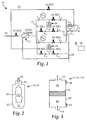
- Filtration system 10 includes a filtering member 12, first and second water-on-water storage vessels 14, 16, a feed line 18, a drain line 20, a service or output line 22, a by-pass line 24 and a tank line 25.
- the filtration system 10 also includes first and second pressure sensors P A , P B , a hydraulic accumulator P C (e.g., a hydropneumatic tank), a plurality of one-way valves So, and a plurality of control valves S1-S8.
- the feed line 18 is connected in fluid communication with the filtering member 12 and a delivery side of each of the first and second storage vessels 14, 16.
- the drain line 20 is connected in fluid communication with the filtering member 12 and the delivery side of each of the first and second storage vessels 14, 16.
- the service or output line 22 is connected in fluid communication with a fill or filtered water side of the first and second storage vessels 14, 16 as well as the by-pass line 24.
- the by-pass line 24 is connected in fluid communication with the feed line 18 and the service line 22 so as to bypass the filter member 12 and first and second storage vessels 14, 16 under certain circumstances described below.
- the tank line 25 is connected in fluid communication with the filtering member 12 and the first and second storage vessels 14, 16.
- each of the first and second storage vessels 14, 16 includes a first container 30, a second container 32, a first input/output opening 34 in fluid communication with the first container 30, and a second input/output opening 36 in fluid communication with the second container 32.
- the first container 30 is shown as a flexible bag member (also referenced as a bladder) that defines a filtered water space 31.
- the second container also referred to as an outer container defines a delivery water space 33.
- the pressure sensors P A , P B monitor a pressure condition in the filtered water storage space 31 and/or in the line that is connected in fluid communication with the space 31 (i.e., the line delivering filtered water from the filter member 12 to the first storage vessel 14 or the line that delivers filtered water from the first storage vessel to the service line 22).
- the filtration system 10 also includes a control system 26 that is electrically connected to the pressure sensors P A , P B , the valves S1-S8, and other controllable features of the filtration system 10.
- the control system 26 controls opening and closing the valves S1-S8 in response to pressure signals received from the pressure sensors P A , P B , and other signals received from other features of the filtration system or an outside system (e.g., a signal representing demand for flow at the output line 22).
- the valves S1-S8 are usually maintained in either a normally open (NO) state or a normally closed (NC) state, as shown in Figure 1 , until a change in system pressure is confirmed by the pressure sensors P A , P B .
- Figure 1 illustrates valves S1, S4, S6 and S8 as normally open, and valves S2, S3, S5 and S7 as normally closed.
- a normally open valve When a normally open valve is actuated (e.g., with an electronic stimulus from the control system 26), the normally open valve changes from an open state to a closed state.
- a normally closed valve When a normally closed valve is actuated, the normally closed valve changes from a closed state to an open state.
- the filtration system 10 is typically triggered from the first pressure sensor P A that monitors the pressure of the filtered water in first container 30 of the first storage vessel 14.
- the valves S1-S8 are set in such a way that filtered water from the filtering member 12 is delivered to the first storage vessel 14 and stored in the first container 30.
- the opposite side of storage vessel 14 (the second container 32) is concurrently open to drain, preferably at atmospheric pressure.
- the second container 32 of the second storage vessel 16 is concurrently open to receive feed water from the feed line 18 that compresses the first container 30 of the second storage vessel 16 to expel filtered water from the second storage vessel 16 to the hydraulic accumulator PC and ultimately to the service line 22. Because the second container 32 of the second storage vessel 16 is filled at the pressure of water in the feed line 18 (i.e., feed pressure), water is expelled from the first container 30 at the feed pressure.
- the pressure sensor P A senses a predetermined high pressure level.
- the control system 26 responds to a high pressure signal from the pressure sensor P A by resetting the valves S1-S8 in such a way that the flow into and out of the first and second storage vessels 14, 16 is switched to fill the first container 32 of the second storage vessel 16 and expel filtered water from the first container 30 of the first storage vessel 14 (i.e., first storage vessel 14 in a service state and second storage vessel 16 in a fill state).
- Filtered water is expelled from the first container 30 of the first storage vessel 14 by opening the flow path to the service line 22 and filling the second container 32 of the first storage vessel 14 with water from the feed line 18, thereby compressing the first container 30.
- the first container 30 of the second storage vessel 16 is filled with filtered water delivered from the filtering member 12 while the second container 32 of the second storage vessel 16 is open to the drain line 20, preferably at atmospheric pressure.
- the pressure sensor P B of the second storage vessel 16 works in conjunction with the first pressure sensor P A and the control system 26 to make sure that if both of the vessels 14, 16 are empty (i.e., the predetermined high pressure level has not been sensed), the valve S2 in the bypass line 24 is open so that water from the feed line 18 can be delivered to the service or output line 22 to meet the requested demand for water. If both of the first and second vessels 14, 16 are full (i.e., the predetermined high pressure level has been met for both vessels), the valve S1 is closed to stop operation of the filtering member 12, which can reduce the waste of water to drain line 20 coming from the filtering member 12.
- the output flow from the filtration system 10 via the service line 22 was not controlled by a hydraulic accumulator P C or any other flow control member. Instead, the service line 22 was left open to atmosphere or to the downstream pressure conditions of demanding water from the filtration system 10.
- the pressure settings for the feed line 18 as well as the high and low pressure settings for the first and second pressure sensors P A , P B can be modified to provide improved stability of the filtration system 10 depending on the demand conditions for water from the filtration system 10.
- the filtration system 100 described below with reference to Figure 4 illustrates a service line 22 without a hydraulic accumulator or other flow control member at the output of the system.
- One example setup for the filtration system 10 includes a one gallon per minute (gpm, 6.309 ⁇ 10 -5 m 3 / s ) flow control valve S1 that substantially matches the output of the filtering member 12 (e.g., a reverse osmosis filtering module having a capability of 6.309 ⁇ 10 -5 m 3 / s (1 gpm)).
- the feed pressure in feed line 18 is regulated to about 413.7 kPA (60 psi), and the high and low predetermined pressure settings for the first and second pressure sensors P A , P B are set at 379.2 kPa (55 psi) and 310.3 kPa (45 psi), respectively.
- the filtered water delivered at the service line 22 at the output of the filtration system 10 was controlled to about 3.155 ⁇ 10 -5 m 3 / s (0.5 gpm) by the hydraulic accumulator P C . Any of these settings can be modified depending on any number of changes to the features, functionality, supply and demand related to the filtration system.
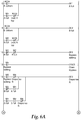
- Figure 3 illustrates an example circuit diagram related to the control of the plurality of valves S1-S8 conducted by the control system 26.
- Figure 3 illustrates that when the first pressure sensor P A is at the high pressure setting, the valves S3, S4, S7, S8 are actuated and the valves S5, S6 are not actuated.
- the first valve S1 may be open to provide a source of feed water to the filtering member 12 as described above.
- the first pressure sensor P A is the dominant sensor that controls when the system switches the first and second storage vessels 14, 16 between fill and service states.
- the second pressure sensor P B could be the dominant sensor.
- the sensors P A , P B are treated equally by the control system so that when the pressure sensors are in one of the high or low states for a given vessel, the control system switches between fill and service for the vessels based on feedback from both sensors P A , P B .
- valves S1-S8 can comprise a variety of valve or regulator types.
- valve S1 is a solenoid valve (e.g., a latching solenoid) that is switched to and maintains an open state or a closed state upon application of a short electronic stimulus.
- any one of valves S1-S8 may be a pressure regulator that maintains an open state or a closed state dependent upon a hydraulic stimulus..
- Filtration system 100 includes many of the same or similar features as described above with reference to filtration system 10.
- Filtration system 100 includes a filtering member 12, first and second water-on-water storage vessels 114, 116, a feed line 18, a drain line 20, a service or output line 22, a bypass line 24, and a plurality of one-way valves S 0 .
- the filtration system 100 also includes a plurality of valves Y004-Y007 and Y010-Y013, and a control system 26 that controls a plurality of valves Y004-Y007 and Y010-Y013.
- the first and second storage vessels 114, 116 are piston style storage vessels that utilize sensors to determine the location of a piston in the vessel, which can be used to understand a fill state of the vessel (see Figure 5 ).
- Some example sensors for use with the storage vessels 114, 116 magnetic proximity sensors, limit switches, level switches, reed switches, and position sensors such as linear encoder, optical and sonar position sensors.
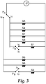
- FIG 5 illustrates an example construction for the storage vessels 114, 116.
- the storage vessel include a container 40, a piston member 42 movable within the container 40 and dividing the container 40 into a filtered water space 44 and a delivery water space 46.
- a first position sensor 48 is positioned at a first end of the container 40 and a second position sensor 50 is positioned at an opposing second end of the container 40.
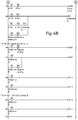
- Sensor signals from the position sensors 48, 50 are labeled as X003-X006 in Figure 4 and the ladder logic program illustrated in Figures 6A and 6B .
- the container 40 includes first and second inlets/outlets 52, 54 positioned at opposing ends of the container 40.
- the position sensors 48, 50 track the position of the piston 42 within the container 40 thereby providing information about the fill state (i.e., full or empty from the filtering member 12) of the storage vessels 114, 116.
- the control system 26 takes inputs from the first and second position sensors 48, 50 to control the open and closed state of the plurality of valves Y004-Y007 and Y010-Y013 in accordance with the PCL ladder logic shown in Figure 6 .
- Output from the position sensors 48, 50 are represented as X003, X004 for the first storage vessel 114, and X005, X006 for the second storage vessel 116.
- the filtration system 100 can also include first and second pressure sensors P A , P B positioned in the line between the filtering member 12 and the first and second storage vessels 114, 116, respectively.
- the first and second pressure sensors P A , P B can provide additional feedback to the control system 26 to confirm a fill state of the first and second storage vessels 114, 116.
- the pressure sensors P A , P B are labeled as inputs X001 and X002, respectively in the logic diagram shown in Figures 6A and 6B .
- One aspect of the examples described above with reference to Figures 1-6B relates to the integrated nature of the control system for controlling when each of the storage vessels is in either a fill or service mode.
- the systems described above include a single filtering member that feeds two separate storage vessels, and the storage vessels deliver filtered water to a single output.
- two separate water filtration systems are connected to a single output or service line, wherein each water filtration system includes a single storage vessel and a separate filtering member.
- a similar control system that integrates control over the valves as described above with reference to Figures 1-6B could be used to control the fill and service states of the storage vessels in each of the filtration systems to provide the desired output of filtered water.
- the example systems described with reference to Figures 1-6B are modified to include three or more storage vessels.
- the control system can be configured to maximize efficiency of production, storage, and delivery of filtered water using all of the storage tanks.
- a filtration system can include two or more filtering members (e.g., filtering member 12 shown in Figure 1 ) arranged in series or in parallel, and that are connected in fluid communication with the storage vessels (e.g., vessels 14, 16) through a tank line (e.g., tank line 25).
- Some example filtering technologies that are possible include reverse osmosis, nano filtration, ultra filtration and other filtration systems that help remove impurities from the water. It is also possible to add supplements to the water in addition to, or in place of, filtering the water using the example systems described herein.
- a bypass line around the filtering member can be added to the example filtration systems. Flow of source water through the bypass line can be adjusted by the user to provide a customized mix of filtered and unfiltered water that is stored in the storage vessels.
- One aspect of the present disclosure relates to a filtration system that includes at least one water filtration member, first and second water-on-water vessels, a plurality of valve members, and a control system.
- the first water-on-water vessel is fluidly connected to the filtration member and configured to alternate between a service state and a fill state.
- the second water-on-water vessel is also fluidly connected to the filtration member and configured to alternate between a service state and a fill state.
- the control system is configured to control the plurality of valve members to switch between service and fill states for the first and second vessels.
- the filtration member can be a reverse osmosis filter.
- a filtration system that includes at least one reverse osmosis water filtration member, first and second vessels, a plurality of valve members, and a control system.
- the first vessel is fluidly connected to the filtration member and configured to alternate between a service state and a fill state.
- the first vessel includes first and second water containers, wherein the first water container has a compressible portion that is positioned within the second container and is configured to retain filtered water received from the filtration member.
- the second vessel is fluidly connected to the filtration member and configured to alternate between a service state and a fill state.
- the second vessel includes first and second water containers, wherein the first water container of the second vessel has a compressible portion that is positioned within the second container of the second vessel and is configured to retain filtered water received from the filtration member.
- the plurality of valve members are in fluid communication with the filtration member and the first and second vessels.
- the control system is configured to control the plurality of valve members to switch the first and second vessels between service and fill states.
- a further aspect of the present disclosure relates to a method of delivering filtered water with a water filtration system.
- the water filtration system includes at least one filtering member, first and second water-on-water storage vessels, a plurality of valves, and a control system.
- the first and second storage vessels are each configured to alternate between a fill state wherein the storage vessel is filled with filtered water, and a service state wherein filtered water is expelled from the storage vessel.
- the method includes steps of generating a supply of filtered water with the filtering member, controlling the plurality of valves with the control system to set the first storage vessel in a fill state and the second storage vessel in a service state, and controlling the plurality of valves with the control system to set the first storage vessel in a service state and the second storage vessel in a fill state.
Landscapes
- Engineering & Computer Science (AREA)
- Water Supply & Treatment (AREA)
- Chemical & Material Sciences (AREA)
- Nanotechnology (AREA)
- Chemical Kinetics & Catalysis (AREA)
- Life Sciences & Earth Sciences (AREA)
- Hydrology & Water Resources (AREA)
- Environmental & Geological Engineering (AREA)
- Organic Chemistry (AREA)
- Separation Using Semi-Permeable Membranes (AREA)
Applications Claiming Priority (2)
| Application Number | Priority Date | Filing Date | Title |
|---|---|---|---|
| US12/027,377 US8257594B2 (en) | 2008-02-07 | 2008-02-07 | Twin tank water-on-water filtration system |
| PCT/US2009/031371 WO2009099747A2 (en) | 2008-02-07 | 2009-01-19 | Twin tank water-on-water filtration system |
Publications (3)
| Publication Number | Publication Date |
|---|---|
| EP2259857A2 EP2259857A2 (en) | 2010-12-15 |
| EP2259857A4 EP2259857A4 (en) | 2012-10-17 |
| EP2259857B1 true EP2259857B1 (en) | 2017-08-09 |
Family
ID=40937996
Family Applications (1)
| Application Number | Title | Priority Date | Filing Date |
|---|---|---|---|
| EP09707861.2A Not-in-force EP2259857B1 (en) | 2008-02-07 | 2009-01-19 | Twin tank water-on-water filtration system |
Country Status (6)
| Country | Link |
|---|---|
| US (1) | US8257594B2 (enExample) |
| EP (1) | EP2259857B1 (enExample) |
| JP (1) | JP5612483B2 (enExample) |
| KR (1) | KR20100114529A (enExample) |
| CN (1) | CN101939070B (enExample) |
| WO (1) | WO2009099747A2 (enExample) |
Families Citing this family (22)
| Publication number | Priority date | Publication date | Assignee | Title |
|---|---|---|---|---|
| US8257594B2 (en) | 2008-02-07 | 2012-09-04 | 3M Innovative Properties Company | Twin tank water-on-water filtration system |
| WO2011082021A1 (en) | 2009-12-29 | 2011-07-07 | 3M Innovative Properties Company | Water-on-water filtration system with precision metering device |
| EP2519864B1 (en) * | 2009-12-29 | 2014-02-26 | 3M Innovative Properties Company | Precision metering device |
| ITPD20110239A1 (it) * | 2011-07-13 | 2013-01-14 | Idropan Dell Orto Depuratori Srl | Impianto per la dissalazione dell'acqua d'una rete idrica e metodo per la dissalazione dell'acqua di una rete idrica in particolare mediante detto impianto. |
| US9873087B2 (en) | 2012-10-11 | 2018-01-23 | 3M Innovative Properties Company | Reverse osmosis water-on-water control valve |
| KR20150065857A (ko) * | 2012-10-11 | 2015-06-15 | 쓰리엠 이노베이티브 프로퍼티즈 컴파니 | 역삼투 워터-온-워터 제어 밸브 |
| US9950298B2 (en) | 2013-09-26 | 2018-04-24 | 3M Innovative Properties Company | Reverse osmosis water-on-water control valve |
| US12350627B2 (en) | 2013-02-28 | 2025-07-08 | Aqua Membranes, Inc. | Permeate flow patterns |
| US11673092B2 (en) | 2016-06-16 | 2023-06-13 | Topper Manufacturing Corporation | Reverse osmosis system control valves |
| US11000807B2 (en) | 2016-06-16 | 2021-05-11 | Topper Manufacturing Corporation | Reverse osmosis system control valves |
| JP2019529099A (ja) | 2016-09-20 | 2019-10-17 | アクア メンブレインズ エルエルシー | 透過流パターン |
| US11040311B2 (en) | 2016-11-19 | 2021-06-22 | Aqua Membranes Inc. | Interference patterns for spiral wound elements |
| US11090612B2 (en) | 2017-04-12 | 2021-08-17 | Aqua Membranes Inc. | Graded spacers for filtration wound elements |
| US11745143B2 (en) | 2017-04-20 | 2023-09-05 | Aqua Membranes, Inc. | Mixing-promoting spacer patterns for spiral-wound elements |
| CN110520210A (zh) | 2017-04-20 | 2019-11-29 | 阿夸曼布拉尼斯公司 | 用于螺旋卷绕元件的不嵌套、不变形图案 |
| WO2019075370A1 (en) | 2017-10-13 | 2019-04-18 | Aqua Membranes Llc | BRIDGE BRACKET AND REDUCED POWER SUPPLIES FOR SPIRAL WINDING ELEMENTS |
| US11072542B2 (en) | 2019-01-17 | 2021-07-27 | A. O. Smith Corporation | High water efficiency TDS creep solution |
| KR102898557B1 (ko) | 2019-01-27 | 2025-12-09 | 아쿠아 멤브레인스 인코포레이티드 | 복합막 |
| WO2021025684A1 (en) | 2019-08-06 | 2021-02-11 | Aqua Membranes Inc. | Preferred flow paths for spiral-wound elements |
| US11633700B2 (en) | 2020-04-07 | 2023-04-25 | Aqua Membranes Inc. | Independent spacers and methods |
| US10882760B1 (en) * | 2020-05-13 | 2021-01-05 | Benjamin John Koppenhoefer | System and method for reducing water pump cycling and TDS creep when producing purified water |
| WO2023129906A1 (en) | 2021-12-28 | 2023-07-06 | Aqua Membranes, Inc. | High rejection spiral wound elements with protective features |
Family Cites Families (31)
| Publication number | Priority date | Publication date | Assignee | Title |
|---|---|---|---|---|
| SE325720B (enExample) | 1967-12-27 | 1970-07-06 | Alfa Laval Ab | |
| FR2240439A1 (en) | 1973-08-06 | 1975-03-07 | Remion Guy | Dosing system for liquids or pastes - has movable volumetric pumps to permit simple and precise dose adjustment |
| US4176063A (en) * | 1977-10-21 | 1979-11-27 | Richard W. Beall, Jr. | Water purifier system and valve |
| DE2830987C2 (de) * | 1978-07-14 | 1982-10-21 | L. & C. Steinmüller GmbH, 5270 Gummersbach | Druckspeicher zur Energierückgewinnung bei der Umkehrosmose |
| ES498326A0 (es) * | 1981-01-05 | 1982-04-01 | Mesple Jose L R | Sistema de desalinizacion de agua por osmosis inversa, con recuperacion de presion |
| DE3225076A1 (de) | 1982-07-05 | 1984-01-05 | Bacillolfabrik Dr. Bode + Co GmbH & Co KG, 2000 Hamburg | Vorrichtung zum zumischen von desinfektionsmittel zu wasser |
| DE3236488A1 (de) * | 1982-10-01 | 1984-04-05 | Richard 8221 Hufschlag Haslberger | Dosiereinrichtung |
| US4895654A (en) * | 1983-01-13 | 1990-01-23 | Burrows Bruce D | Purified water dispensing and reject water control valve assembly |
| US4623467A (en) * | 1984-06-25 | 1986-11-18 | International Manufacturing And Water Vending Company | Water purifying and vending apparatus |
| US4776952A (en) * | 1984-07-23 | 1988-10-11 | Burrows Bruce D | Regulated control valve assembly for a water purification system |
| US4705625A (en) * | 1985-10-31 | 1987-11-10 | Hart Jr John E | Reverse osmosis water purifying system |
| US4695375A (en) * | 1986-05-27 | 1987-09-22 | Tyler Truman V | Self-contained hydraulically operable water purifier |
| US5060824A (en) * | 1986-07-18 | 1991-10-29 | The Coca-Cola Company | Beverage dispenser system using volumetric ratio control device |
| US5181631A (en) * | 1986-07-18 | 1993-01-26 | The Coca-Cola Company | Beverage dispenser valve with controllable flow rate |
| US4909934A (en) * | 1987-06-03 | 1990-03-20 | Eastman Kodak Company | Water purification system |
| WO1990002702A1 (en) | 1988-09-16 | 1990-03-22 | Milton Roy Company | Beverage dispenser |
| US5096574A (en) * | 1990-01-16 | 1992-03-17 | Teledyne Industries, Inc. | Reverse osmosis system |
| FI90408C (fi) | 1990-10-19 | 1994-02-10 | Tauno Pirhonen | Sekoituspumppu |
| US5254243A (en) * | 1992-06-22 | 1993-10-19 | Whirlpool Corporation | Water conditioning system and an electronic control therefor |
| US5366159A (en) * | 1992-09-14 | 1994-11-22 | Childers Lance L | Automatic lawn and garden feeding apparatus |
| US5520816A (en) * | 1994-08-18 | 1996-05-28 | Kuepper; Theodore A. | Zero waste effluent desalination system |
| DE69731320T2 (de) * | 1996-08-07 | 2006-02-23 | Cuno Inc., Meriden | Abgabevorrichtung für additive |
| US6228255B1 (en) | 1998-07-24 | 2001-05-08 | Dialysis Systems, Inc. | Portable water treatment facility |
| US6110360A (en) * | 1998-09-04 | 2000-08-29 | Hart, Jr.; John E. | Low pressure reverse osmosis water purifying system |
| US6764595B1 (en) * | 2000-03-15 | 2004-07-20 | Kinetico Incorporated | Fluid treatment system |
| GB2377928B (en) * | 2001-07-26 | 2004-09-22 | Finch Ltd | Desalination system |
| US7316774B2 (en) * | 2002-07-22 | 2008-01-08 | Kinetico Incorporated | Fluid treatment system |
| US20040164022A1 (en) * | 2003-02-24 | 2004-08-26 | Solomon Donald F. | Reverse osmosis system |
| CA2437901C (en) * | 2003-08-19 | 2004-06-01 | 4131827 Manitoba Ltd. | Reduced-waste reverse osmosis water supply system |
| US7550084B2 (en) * | 2006-05-02 | 2009-06-23 | Watts Water Technologies, Inc. | Reverse osmosis water filtering system |
| US8257594B2 (en) | 2008-02-07 | 2012-09-04 | 3M Innovative Properties Company | Twin tank water-on-water filtration system |
-
2008
- 2008-02-07 US US12/027,377 patent/US8257594B2/en not_active Expired - Fee Related
-
2009
- 2009-01-19 CN CN2009801043675A patent/CN101939070B/zh active Active
- 2009-01-19 KR KR1020107018721A patent/KR20100114529A/ko not_active Ceased
- 2009-01-19 EP EP09707861.2A patent/EP2259857B1/en not_active Not-in-force
- 2009-01-19 JP JP2010545925A patent/JP5612483B2/ja not_active Expired - Fee Related
- 2009-01-19 WO PCT/US2009/031371 patent/WO2009099747A2/en not_active Ceased
Non-Patent Citations (1)
| Title |
|---|
| None * |
Also Published As
| Publication number | Publication date |
|---|---|
| CN101939070A (zh) | 2011-01-05 |
| JP2011510815A (ja) | 2011-04-07 |
| EP2259857A4 (en) | 2012-10-17 |
| US8257594B2 (en) | 2012-09-04 |
| CN101939070B (zh) | 2013-11-06 |
| EP2259857A2 (en) | 2010-12-15 |
| WO2009099747A3 (en) | 2009-10-08 |
| JP5612483B2 (ja) | 2014-10-22 |
| KR20100114529A (ko) | 2010-10-25 |
| US20090200238A1 (en) | 2009-08-13 |
| WO2009099747A2 (en) | 2009-08-13 |
Similar Documents
| Publication | Publication Date | Title |
|---|---|---|
| EP2259857B1 (en) | Twin tank water-on-water filtration system | |
| US5254243A (en) | Water conditioning system and an electronic control therefor | |
| EP3214046B1 (en) | Liquid purification system | |
| US6764595B1 (en) | Fluid treatment system | |
| US7316774B2 (en) | Fluid treatment system | |
| US4626346A (en) | Reverse osmosis water purification system for use in limited water supply installations | |
| US3887463A (en) | Reverse osmosis system with automatic valve for module operation control | |
| EP3241807B1 (en) | Method for purifying liquid | |
| EP2906323B1 (en) | Reverse osmosis water-on-water control valve | |
| CN105036249A (zh) | 节水型反渗透净水器 | |
| US3493495A (en) | Apparatus and process for the osmotic separation of water from a saline solution | |
| EP2934719B1 (en) | Method of cleaning a filter element | |
| EP2371445A1 (en) | Reverse osmosis plant for the treatment of water | |
| CN211367187U (zh) | 一种可降低首杯水tds值的净水系统 | |
| CN210764673U (zh) | 一种模块化设计的组合式二级反渗透海水淡化装置 | |
| EP3131662B1 (en) | Apparatus for treating water or liquids in general | |
| CN223254985U (zh) | 一种ro净水器的净水储存废水回收统一利用装置及包含该装置的ro净水系统 | |
| CA2400949C (en) | Fluid treatment system | |
| EP2216299A1 (en) | Method and device for purification of water | |
| RU2006121054A (ru) | Способ концентрирования водных растворов биологически активных веществ и установка для его реализации | |
| CN103787463A (zh) | 一种运用压缩空气作为驱动能量的膜法水处理系统 | |
| JP3340170B2 (ja) | 循環浄水装置 | |
| CN211226407U (zh) | 稳压桶及净水机 | |
| CN211328448U (zh) | 净水器净水系统 | |
| JPH05125750A (ja) | 浄水装置及び方法 |
Legal Events
| Date | Code | Title | Description |
|---|---|---|---|
| PUAI | Public reference made under article 153(3) epc to a published international application that has entered the european phase |
Free format text: ORIGINAL CODE: 0009012 |
|
| 17P | Request for examination filed |
Effective date: 20100927 |
|
| AK | Designated contracting states |
Kind code of ref document: A2 Designated state(s): AT BE BG CH CY CZ DE DK EE ES FI FR GB GR HR HU IE IS IT LI LT LU LV MC MK MT NL NO PL PT RO SE SI SK TR |
|
| AX | Request for extension of the european patent |
Extension state: AL BA RS |
|
| DAX | Request for extension of the european patent (deleted) | ||
| A4 | Supplementary search report drawn up and despatched |
Effective date: 20120917 |
|
| RIC1 | Information provided on ipc code assigned before grant |
Ipc: B01D 35/00 20060101AFI20120911BHEP Ipc: C02F 1/44 20060101ALN20120911BHEP Ipc: F24D 3/10 20060101ALI20120911BHEP Ipc: B01D 61/10 20060101ALN20120911BHEP Ipc: B01D 61/12 20060101ALN20120911BHEP |
|
| 17Q | First examination report despatched |
Effective date: 20140213 |
|
| GRAP | Despatch of communication of intention to grant a patent |
Free format text: ORIGINAL CODE: EPIDOSNIGR1 |
|
| RIC1 | Information provided on ipc code assigned before grant |
Ipc: B01D 61/10 20060101ALN20160503BHEP Ipc: F24D 3/10 20060101ALI20160503BHEP Ipc: B01D 35/00 20060101AFI20160503BHEP Ipc: B01D 61/12 20060101ALN20160503BHEP Ipc: C02F 1/44 20060101ALN20160503BHEP |
|
| INTG | Intention to grant announced |
Effective date: 20160608 |
|
| GRAJ | Information related to disapproval of communication of intention to grant by the applicant or resumption of examination proceedings by the epo deleted |
Free format text: ORIGINAL CODE: EPIDOSDIGR1 |
|
| INTC | Intention to grant announced (deleted) | ||
| GRAP | Despatch of communication of intention to grant a patent |
Free format text: ORIGINAL CODE: EPIDOSNIGR1 |
|
| STAA | Information on the status of an ep patent application or granted ep patent |
Free format text: STATUS: GRANT OF PATENT IS INTENDED |
|
| RIC1 | Information provided on ipc code assigned before grant |
Ipc: B01D 61/10 20060101ALN20161124BHEP Ipc: C02F 1/44 20060101ALN20161124BHEP Ipc: B01D 35/00 20060101AFI20161124BHEP Ipc: F24D 3/10 20060101ALI20161124BHEP Ipc: B01D 61/12 20060101ALN20161124BHEP |
|
| INTG | Intention to grant announced |
Effective date: 20161221 |
|
| GRAS | Grant fee paid |
Free format text: ORIGINAL CODE: EPIDOSNIGR3 |
|
| GRAJ | Information related to disapproval of communication of intention to grant by the applicant or resumption of examination proceedings by the epo deleted |
Free format text: ORIGINAL CODE: EPIDOSDIGR1 |
|
| GRAL | Information related to payment of fee for publishing/printing deleted |
Free format text: ORIGINAL CODE: EPIDOSDIGR3 |
|
| STAA | Information on the status of an ep patent application or granted ep patent |
Free format text: STATUS: EXAMINATION IS IN PROGRESS |
|
| INTC | Intention to grant announced (deleted) | ||
| RIC1 | Information provided on ipc code assigned before grant |
Ipc: B01D 61/12 20060101ALN20170508BHEP Ipc: B01D 35/00 20060101AFI20170508BHEP Ipc: C02F 1/44 20060101ALN20170508BHEP Ipc: F24D 3/10 20060101ALI20170508BHEP Ipc: B01D 61/10 20060101ALN20170508BHEP |
|
| GRAR | Information related to intention to grant a patent recorded |
Free format text: ORIGINAL CODE: EPIDOSNIGR71 |
|
| STAA | Information on the status of an ep patent application or granted ep patent |
Free format text: STATUS: GRANT OF PATENT IS INTENDED |
|
| GRAA | (expected) grant |
Free format text: ORIGINAL CODE: 0009210 |
|
| STAA | Information on the status of an ep patent application or granted ep patent |
Free format text: STATUS: THE PATENT HAS BEEN GRANTED |
|
| RIC1 | Information provided on ipc code assigned before grant |
Ipc: B01D 61/10 20060101ALN20170612BHEP Ipc: F24D 3/10 20060101ALI20170612BHEP Ipc: C02F 1/44 20060101ALN20170612BHEP Ipc: B01D 61/12 20060101ALN20170612BHEP Ipc: B01D 35/00 20060101AFI20170612BHEP |
|
| INTG | Intention to grant announced |
Effective date: 20170628 |
|
| AK | Designated contracting states |
Kind code of ref document: B1 Designated state(s): AT BE BG CH CY CZ DE DK EE ES FI FR GB GR HR HU IE IS IT LI LT LU LV MC MK MT NL NO PL PT RO SE SI SK TR |
|
| REG | Reference to a national code |
Ref country code: GB Ref legal event code: FG4D |
|
| REG | Reference to a national code |
Ref country code: AT Ref legal event code: REF Ref document number: 916202 Country of ref document: AT Kind code of ref document: T Effective date: 20170815 Ref country code: CH Ref legal event code: EP |
|
| REG | Reference to a national code |
Ref country code: IE Ref legal event code: FG4D |
|
| REG | Reference to a national code |
Ref country code: DE Ref legal event code: R096 Ref document number: 602009047623 Country of ref document: DE |
|
| REG | Reference to a national code |
Ref country code: NL Ref legal event code: MP Effective date: 20170809 |
|
| REG | Reference to a national code |
Ref country code: LT Ref legal event code: MG4D |
|
| REG | Reference to a national code |
Ref country code: AT Ref legal event code: MK05 Ref document number: 916202 Country of ref document: AT Kind code of ref document: T Effective date: 20170809 |
|
| PG25 | Lapsed in a contracting state [announced via postgrant information from national office to epo] |
Ref country code: AT Free format text: LAPSE BECAUSE OF FAILURE TO SUBMIT A TRANSLATION OF THE DESCRIPTION OR TO PAY THE FEE WITHIN THE PRESCRIBED TIME-LIMIT Effective date: 20170809 Ref country code: FI Free format text: LAPSE BECAUSE OF FAILURE TO SUBMIT A TRANSLATION OF THE DESCRIPTION OR TO PAY THE FEE WITHIN THE PRESCRIBED TIME-LIMIT Effective date: 20170809 Ref country code: LT Free format text: LAPSE BECAUSE OF FAILURE TO SUBMIT A TRANSLATION OF THE DESCRIPTION OR TO PAY THE FEE WITHIN THE PRESCRIBED TIME-LIMIT Effective date: 20170809 Ref country code: HR Free format text: LAPSE BECAUSE OF FAILURE TO SUBMIT A TRANSLATION OF THE DESCRIPTION OR TO PAY THE FEE WITHIN THE PRESCRIBED TIME-LIMIT Effective date: 20170809 Ref country code: SE Free format text: LAPSE BECAUSE OF FAILURE TO SUBMIT A TRANSLATION OF THE DESCRIPTION OR TO PAY THE FEE WITHIN THE PRESCRIBED TIME-LIMIT Effective date: 20170809 Ref country code: NL Free format text: LAPSE BECAUSE OF FAILURE TO SUBMIT A TRANSLATION OF THE DESCRIPTION OR TO PAY THE FEE WITHIN THE PRESCRIBED TIME-LIMIT Effective date: 20170809 Ref country code: NO Free format text: LAPSE BECAUSE OF FAILURE TO SUBMIT A TRANSLATION OF THE DESCRIPTION OR TO PAY THE FEE WITHIN THE PRESCRIBED TIME-LIMIT Effective date: 20171109 |
|
| PG25 | Lapsed in a contracting state [announced via postgrant information from national office to epo] |
Ref country code: LV Free format text: LAPSE BECAUSE OF FAILURE TO SUBMIT A TRANSLATION OF THE DESCRIPTION OR TO PAY THE FEE WITHIN THE PRESCRIBED TIME-LIMIT Effective date: 20170809 Ref country code: BG Free format text: LAPSE BECAUSE OF FAILURE TO SUBMIT A TRANSLATION OF THE DESCRIPTION OR TO PAY THE FEE WITHIN THE PRESCRIBED TIME-LIMIT Effective date: 20171109 Ref country code: ES Free format text: LAPSE BECAUSE OF FAILURE TO SUBMIT A TRANSLATION OF THE DESCRIPTION OR TO PAY THE FEE WITHIN THE PRESCRIBED TIME-LIMIT Effective date: 20170809 Ref country code: IS Free format text: LAPSE BECAUSE OF FAILURE TO SUBMIT A TRANSLATION OF THE DESCRIPTION OR TO PAY THE FEE WITHIN THE PRESCRIBED TIME-LIMIT Effective date: 20171209 Ref country code: PL Free format text: LAPSE BECAUSE OF FAILURE TO SUBMIT A TRANSLATION OF THE DESCRIPTION OR TO PAY THE FEE WITHIN THE PRESCRIBED TIME-LIMIT Effective date: 20170809 Ref country code: GR Free format text: LAPSE BECAUSE OF FAILURE TO SUBMIT A TRANSLATION OF THE DESCRIPTION OR TO PAY THE FEE WITHIN THE PRESCRIBED TIME-LIMIT Effective date: 20171110 |
|
| PG25 | Lapsed in a contracting state [announced via postgrant information from national office to epo] |
Ref country code: RO Free format text: LAPSE BECAUSE OF FAILURE TO SUBMIT A TRANSLATION OF THE DESCRIPTION OR TO PAY THE FEE WITHIN THE PRESCRIBED TIME-LIMIT Effective date: 20170809 Ref country code: DK Free format text: LAPSE BECAUSE OF FAILURE TO SUBMIT A TRANSLATION OF THE DESCRIPTION OR TO PAY THE FEE WITHIN THE PRESCRIBED TIME-LIMIT Effective date: 20170809 Ref country code: CZ Free format text: LAPSE BECAUSE OF FAILURE TO SUBMIT A TRANSLATION OF THE DESCRIPTION OR TO PAY THE FEE WITHIN THE PRESCRIBED TIME-LIMIT Effective date: 20170809 |
|
| REG | Reference to a national code |
Ref country code: DE Ref legal event code: R097 Ref document number: 602009047623 Country of ref document: DE |
|
| PG25 | Lapsed in a contracting state [announced via postgrant information from national office to epo] |
Ref country code: EE Free format text: LAPSE BECAUSE OF FAILURE TO SUBMIT A TRANSLATION OF THE DESCRIPTION OR TO PAY THE FEE WITHIN THE PRESCRIBED TIME-LIMIT Effective date: 20170809 Ref country code: SK Free format text: LAPSE BECAUSE OF FAILURE TO SUBMIT A TRANSLATION OF THE DESCRIPTION OR TO PAY THE FEE WITHIN THE PRESCRIBED TIME-LIMIT Effective date: 20170809 Ref country code: IT Free format text: LAPSE BECAUSE OF FAILURE TO SUBMIT A TRANSLATION OF THE DESCRIPTION OR TO PAY THE FEE WITHIN THE PRESCRIBED TIME-LIMIT Effective date: 20170809 |
|
| PLBE | No opposition filed within time limit |
Free format text: ORIGINAL CODE: 0009261 |
|
| STAA | Information on the status of an ep patent application or granted ep patent |
Free format text: STATUS: NO OPPOSITION FILED WITHIN TIME LIMIT |
|
| 26N | No opposition filed |
Effective date: 20180511 |
|
| PG25 | Lapsed in a contracting state [announced via postgrant information from national office to epo] |
Ref country code: SI Free format text: LAPSE BECAUSE OF FAILURE TO SUBMIT A TRANSLATION OF THE DESCRIPTION OR TO PAY THE FEE WITHIN THE PRESCRIBED TIME-LIMIT Effective date: 20170809 |
|
| REG | Reference to a national code |
Ref country code: CH Ref legal event code: PL |
|
| GBPC | Gb: european patent ceased through non-payment of renewal fee |
Effective date: 20180119 |
|
| PG25 | Lapsed in a contracting state [announced via postgrant information from national office to epo] |
Ref country code: LU Free format text: LAPSE BECAUSE OF NON-PAYMENT OF DUE FEES Effective date: 20180119 Ref country code: FR Free format text: LAPSE BECAUSE OF NON-PAYMENT OF DUE FEES Effective date: 20180131 |
|
| REG | Reference to a national code |
Ref country code: IE Ref legal event code: MM4A |
|
| REG | Reference to a national code |
Ref country code: FR Ref legal event code: ST Effective date: 20180928 |
|
| REG | Reference to a national code |
Ref country code: BE Ref legal event code: MM Effective date: 20180131 |
|
| PG25 | Lapsed in a contracting state [announced via postgrant information from national office to epo] |
Ref country code: GB Free format text: LAPSE BECAUSE OF NON-PAYMENT OF DUE FEES Effective date: 20180119 Ref country code: BE Free format text: LAPSE BECAUSE OF NON-PAYMENT OF DUE FEES Effective date: 20180131 Ref country code: LI Free format text: LAPSE BECAUSE OF NON-PAYMENT OF DUE FEES Effective date: 20180131 Ref country code: CH Free format text: LAPSE BECAUSE OF NON-PAYMENT OF DUE FEES Effective date: 20180131 |
|
| PG25 | Lapsed in a contracting state [announced via postgrant information from national office to epo] |
Ref country code: IE Free format text: LAPSE BECAUSE OF NON-PAYMENT OF DUE FEES Effective date: 20180119 |
|
| PG25 | Lapsed in a contracting state [announced via postgrant information from national office to epo] |
Ref country code: MC Free format text: LAPSE BECAUSE OF FAILURE TO SUBMIT A TRANSLATION OF THE DESCRIPTION OR TO PAY THE FEE WITHIN THE PRESCRIBED TIME-LIMIT Effective date: 20170809 |
|
| PG25 | Lapsed in a contracting state [announced via postgrant information from national office to epo] |
Ref country code: MT Free format text: LAPSE BECAUSE OF NON-PAYMENT OF DUE FEES Effective date: 20180119 |
|
| PG25 | Lapsed in a contracting state [announced via postgrant information from national office to epo] |
Ref country code: TR Free format text: LAPSE BECAUSE OF FAILURE TO SUBMIT A TRANSLATION OF THE DESCRIPTION OR TO PAY THE FEE WITHIN THE PRESCRIBED TIME-LIMIT Effective date: 20170809 |
|
| PGFP | Annual fee paid to national office [announced via postgrant information from national office to epo] |
Ref country code: DE Payment date: 20200107 Year of fee payment: 12 |
|
| PG25 | Lapsed in a contracting state [announced via postgrant information from national office to epo] |
Ref country code: HU Free format text: LAPSE BECAUSE OF FAILURE TO SUBMIT A TRANSLATION OF THE DESCRIPTION OR TO PAY THE FEE WITHIN THE PRESCRIBED TIME-LIMIT; INVALID AB INITIO Effective date: 20090119 Ref country code: PT Free format text: LAPSE BECAUSE OF FAILURE TO SUBMIT A TRANSLATION OF THE DESCRIPTION OR TO PAY THE FEE WITHIN THE PRESCRIBED TIME-LIMIT Effective date: 20170809 |
|
| PG25 | Lapsed in a contracting state [announced via postgrant information from national office to epo] |
Ref country code: MK Free format text: LAPSE BECAUSE OF NON-PAYMENT OF DUE FEES Effective date: 20170809 Ref country code: CY Free format text: LAPSE BECAUSE OF FAILURE TO SUBMIT A TRANSLATION OF THE DESCRIPTION OR TO PAY THE FEE WITHIN THE PRESCRIBED TIME-LIMIT Effective date: 20170809 |
|
| REG | Reference to a national code |
Ref country code: DE Ref legal event code: R119 Ref document number: 602009047623 Country of ref document: DE |
|
| PG25 | Lapsed in a contracting state [announced via postgrant information from national office to epo] |
Ref country code: DE Free format text: LAPSE BECAUSE OF NON-PAYMENT OF DUE FEES Effective date: 20210803 |