EP2259257A1 - Information processing device, method of controlling information processing device, control program for information processing device, and recording medium wherein control program for information processing device is recorded - Google Patents
Information processing device, method of controlling information processing device, control program for information processing device, and recording medium wherein control program for information processing device is recorded Download PDFInfo
- Publication number
- EP2259257A1 EP2259257A1 EP09722132A EP09722132A EP2259257A1 EP 2259257 A1 EP2259257 A1 EP 2259257A1 EP 09722132 A EP09722132 A EP 09722132A EP 09722132 A EP09722132 A EP 09722132A EP 2259257 A1 EP2259257 A1 EP 2259257A1
- Authority
- EP
- European Patent Office
- Prior art keywords
- data
- optical disk
- recording
- pieces
- recorded
- Prior art date
- Legal status (The legal status is an assumption and is not a legal conclusion. Google has not performed a legal analysis and makes no representation as to the accuracy of the status listed.)
- Withdrawn
Links
- 238000000034 method Methods 0.000 title claims description 83
- 230000010365 information processing Effects 0.000 title claims description 63
- 230000003287 optical effect Effects 0.000 claims abstract description 384
- 230000001678 irradiating effect Effects 0.000 claims description 10
- 230000008569 process Effects 0.000 description 61
- 238000007726 management method Methods 0.000 description 7
- 230000004044 response Effects 0.000 description 7
- 238000004364 calculation method Methods 0.000 description 6
- 238000007796 conventional method Methods 0.000 description 6
- 238000012937 correction Methods 0.000 description 4
- 238000010586 diagram Methods 0.000 description 4
- 230000000694 effects Effects 0.000 description 4
- 230000006870 function Effects 0.000 description 3
- ZZUFCTLCJUWOSV-UHFFFAOYSA-N furosemide Chemical compound C1=C(Cl)C(S(=O)(=O)N)=CC(C(O)=O)=C1NCC1=CC=CO1 ZZUFCTLCJUWOSV-UHFFFAOYSA-N 0.000 description 3
- 230000008859 change Effects 0.000 description 2
- 239000000470 constituent Substances 0.000 description 2
- 238000013500 data storage Methods 0.000 description 2
- 201000002266 mite infestation Diseases 0.000 description 2
- 238000012360 testing method Methods 0.000 description 2
- 238000003491 array Methods 0.000 description 1
- 230000015572 biosynthetic process Effects 0.000 description 1
- 238000011109 contamination Methods 0.000 description 1
- 230000006866 deterioration Effects 0.000 description 1
- 230000006872 improvement Effects 0.000 description 1
- 239000000463 material Substances 0.000 description 1
Images







Classifications
-
- G—PHYSICS
- G11—INFORMATION STORAGE
- G11B—INFORMATION STORAGE BASED ON RELATIVE MOVEMENT BETWEEN RECORD CARRIER AND TRANSDUCER
- G11B7/00—Recording or reproducing by optical means, e.g. recording using a thermal beam of optical radiation by modifying optical properties or the physical structure, reproducing using an optical beam at lower power by sensing optical properties; Record carriers therefor
- G11B7/007—Arrangement of the information on the record carrier, e.g. form of tracks, actual track shape, e.g. wobbled, or cross-section, e.g. v-shaped; Sequential information structures, e.g. sectoring or header formats within a track
- G11B7/00736—Auxiliary data, e.g. lead-in, lead-out, Power Calibration Area [PCA], Burst Cutting Area [BCA], control information
-
- G—PHYSICS
- G11—INFORMATION STORAGE
- G11B—INFORMATION STORAGE BASED ON RELATIVE MOVEMENT BETWEEN RECORD CARRIER AND TRANSDUCER
- G11B20/00—Signal processing not specific to the method of recording or reproducing; Circuits therefor
- G11B20/10—Digital recording or reproducing
- G11B20/12—Formatting, e.g. arrangement of data block or words on the record carriers
- G11B20/1217—Formatting, e.g. arrangement of data block or words on the record carriers on discs
-
- G—PHYSICS
- G11—INFORMATION STORAGE
- G11B—INFORMATION STORAGE BASED ON RELATIVE MOVEMENT BETWEEN RECORD CARRIER AND TRANSDUCER
- G11B20/00—Signal processing not specific to the method of recording or reproducing; Circuits therefor
- G11B20/10—Digital recording or reproducing
- G11B20/18—Error detection or correction; Testing, e.g. of drop-outs
- G11B20/1833—Error detection or correction; Testing, e.g. of drop-outs by adding special lists or symbols to the coded information
-
- G—PHYSICS
- G11—INFORMATION STORAGE
- G11B—INFORMATION STORAGE BASED ON RELATIVE MOVEMENT BETWEEN RECORD CARRIER AND TRANSDUCER
- G11B7/00—Recording or reproducing by optical means, e.g. recording using a thermal beam of optical radiation by modifying optical properties or the physical structure, reproducing using an optical beam at lower power by sensing optical properties; Record carriers therefor
- G11B7/007—Arrangement of the information on the record carrier, e.g. form of tracks, actual track shape, e.g. wobbled, or cross-section, e.g. v-shaped; Sequential information structures, e.g. sectoring or header formats within a track
-
- G—PHYSICS
- G11—INFORMATION STORAGE
- G11B—INFORMATION STORAGE BASED ON RELATIVE MOVEMENT BETWEEN RECORD CARRIER AND TRANSDUCER
- G11B7/00—Recording or reproducing by optical means, e.g. recording using a thermal beam of optical radiation by modifying optical properties or the physical structure, reproducing using an optical beam at lower power by sensing optical properties; Record carriers therefor
- G11B2007/0003—Recording, reproducing or erasing systems characterised by the structure or type of the carrier
- G11B2007/0009—Recording, reproducing or erasing systems characterised by the structure or type of the carrier for carriers having data stored in three dimensions, e.g. volume storage
- G11B2007/0013—Recording, reproducing or erasing systems characterised by the structure or type of the carrier for carriers having data stored in three dimensions, e.g. volume storage for carriers having multiple discrete layers
-
- G—PHYSICS
- G11—INFORMATION STORAGE
- G11B—INFORMATION STORAGE BASED ON RELATIVE MOVEMENT BETWEEN RECORD CARRIER AND TRANSDUCER
- G11B20/00—Signal processing not specific to the method of recording or reproducing; Circuits therefor
- G11B20/10—Digital recording or reproducing
- G11B20/12—Formatting, e.g. arrangement of data block or words on the record carriers
- G11B20/1217—Formatting, e.g. arrangement of data block or words on the record carriers on discs
- G11B2020/1218—Formatting, e.g. arrangement of data block or words on the record carriers on discs wherein the formatting concerns a specific area of the disc
- G11B2020/1232—Formatting, e.g. arrangement of data block or words on the record carriers on discs wherein the formatting concerns a specific area of the disc sector, i.e. the minimal addressable physical data unit
-
- G—PHYSICS
- G11—INFORMATION STORAGE
- G11B—INFORMATION STORAGE BASED ON RELATIVE MOVEMENT BETWEEN RECORD CARRIER AND TRANSDUCER
- G11B20/00—Signal processing not specific to the method of recording or reproducing; Circuits therefor
- G11B20/10—Digital recording or reproducing
- G11B20/12—Formatting, e.g. arrangement of data block or words on the record carriers
- G11B2020/1264—Formatting, e.g. arrangement of data block or words on the record carriers wherein the formatting concerns a specific kind of data
- G11B2020/1265—Control data, system data or management information, i.e. data used to access or process user data
- G11B2020/1267—Address data
-
- G—PHYSICS
- G11—INFORMATION STORAGE
- G11B—INFORMATION STORAGE BASED ON RELATIVE MOVEMENT BETWEEN RECORD CARRIER AND TRANSDUCER
- G11B2220/00—Record carriers by type
- G11B2220/20—Disc-shaped record carriers
- G11B2220/23—Disc-shaped record carriers characterised in that the disc has a specific layer structure
- G11B2220/235—Multilayer discs, i.e. multiple recording layers accessed from the same side
-
- G—PHYSICS
- G11—INFORMATION STORAGE
- G11B—INFORMATION STORAGE BASED ON RELATIVE MOVEMENT BETWEEN RECORD CARRIER AND TRANSDUCER
- G11B2220/00—Record carriers by type
- G11B2220/20—Disc-shaped record carriers
- G11B2220/25—Disc-shaped record carriers characterised in that the disc is based on a specific recording technology
- G11B2220/2537—Optical discs
-
- G—PHYSICS
- G11—INFORMATION STORAGE
- G11B—INFORMATION STORAGE BASED ON RELATIVE MOVEMENT BETWEEN RECORD CARRIER AND TRANSDUCER
- G11B27/00—Editing; Indexing; Addressing; Timing or synchronising; Monitoring; Measuring tape travel
- G11B27/10—Indexing; Addressing; Timing or synchronising; Measuring tape travel
- G11B27/19—Indexing; Addressing; Timing or synchronising; Measuring tape travel by using information detectable on the record carrier
- G11B27/28—Indexing; Addressing; Timing or synchronising; Measuring tape travel by using information detectable on the record carrier by using information signals recorded by the same method as the main recording
- G11B27/32—Indexing; Addressing; Timing or synchronising; Measuring tape travel by using information detectable on the record carrier by using information signals recorded by the same method as the main recording on separate auxiliary tracks of the same or an auxiliary record carrier
-
- G—PHYSICS
- G11—INFORMATION STORAGE
- G11B—INFORMATION STORAGE BASED ON RELATIVE MOVEMENT BETWEEN RECORD CARRIER AND TRANSDUCER
- G11B7/00—Recording or reproducing by optical means, e.g. recording using a thermal beam of optical radiation by modifying optical properties or the physical structure, reproducing using an optical beam at lower power by sensing optical properties; Record carriers therefor
- G11B7/24—Record carriers characterised by shape, structure or physical properties, or by the selection of the material
- G11B7/2403—Layers; Shape, structure or physical properties thereof
- G11B7/24035—Recording layers
- G11B7/24038—Multiple laminated recording layers
Definitions
- the present invention relates to an information processing apparatus for recording data by irradiating light to an optical disk having a plurality of recording layers in which to store data, a control method for controlling the information processing apparatus, a control program of the information processing apparatus, and a storage medium in which the control program of the information processing apparatus is stored.
- an error such as noise contamination happens when data is read via communications over a network or from a memory medium, it is detected from a redundant code preliminarily added to the data whether or not any error occurs. If there is an error, error correction is conventionally carried out so as to reproduce original data. However, in cases where a given data amount includes many errors, the data cannot be reconstructed properly. For example, there are some cases where a recording device, such as a hard disk or an optical disk apparatus, cannot carry out the error correction with respect to a storage medium because the storage medium is damaged due to an impact or the like. Especially, in a case where the storage medium is an optical disk, a recording surface thereof is touchable by hand directly.
- the direct touch to the recording surface may possibly cause so big a damage on the storage medium that the error correction cannot be performed on the storage medium. Further, in some cases, the optical disk itself deteriorates so much due to direct or indirect sunlight that the error correction cannot be performed on the storage medium.
- the technique is called RAID (Redundant Arrays of Inexpensive Disks).
- the RAID is a technique in which (i) original data to be recorded is split into a plurality of pieces of sub data, and (ii) the plurality of pieces of sub data are recorded into a plurality of hard disks, respectively, in a distributed manner. At the time when the pieces of sub data are recorded into to the respective plurality of hard disks in a distributed manner, parity information is added to the pieces of sub data. With this arrangement, even if reading of data from any of the plurality of hard disks is failed, it is still possible to reconstruct the original data properly based on the other piece(s) of data read from the other hard disk(s).
- Patent Literature 1 Another technique in which a single hard disk is arranged in the following manner so as to a realize mirroring function. More specifically, the technique disclosed in Patent Literature 1 is so arranged that data recording is carried out such that data is written into 2 portions in a data storage medium, and data reading is carried out such that the data is read from either one of the 2 portions. With the arrangement, even if either one of the pieces of data causes an error, the other one of the pieces of data can be read.
- an information processing apparatus for performing data recording on a single optical disk including a plurality of recording layers in such a manner that data and its backup data for reconstructing the data are recorded into respective recording layers among the plurality of recording layers or individually recorded into the same layer (Patent Literature 2).
- the information processing apparatus arranged as such can achieve an improvement in efficiency of recording data and its backup data.
- the optical disk in which data is recorded into a plurality of layers is arranged such that in a case where respective pieces of data are read from or recorded into different recording layers (for example, a recording layer 100 and a recording layer 200), light emitted from an optical head toward the optical disk is focused on a target layer where data is to be read from or recorded in (see Fig. 23 and Fig. 24).
- Fig. 23 and Fig. 24 show the conventional technique, each illustrating how light from the optical head is irradiated to a recording layer (100, 200) at the time of data recording or data reading.
- 26 show the conventional technique, each illustrating (i) data recorded in a recording layer (100, 200) and (ii) how light from an optical head is irradiated to the recording layer, in a case where a protection layer (300) of an optical disk is damaged.
- Patent Literature 1 described above does not improve the reliability of reconstruction of lost data in the optical disk in which data is recordable in a plurality of layers. Further, Patent Literature 2 does not prevent the problem that both of the data and the reconstruction data become unreadable due to the single scratch on the protection layer 300.
- Patent Literature 1 Japanese Patent Application Publication, Tokukaihei, No. 4-349273 (Publication Date: December 3, 1992 )
- Patent Literature 2 Japanese Patent Application Publication, Tokukai, No. 2007-26600 (Publication Date: February 1, 2007 )
- An object of the present invention is to realize an information processing apparatus that can improve reliability of data reconstruction in a case where loss of recorded data occurs in an optical disk in which data is recordable in a plurality of layers, a control method for controlling the information processing apparatus, a control program of the information processing apparatus, and a storage medium in which the control program of the information processing apparatus is stored.
- An information processing apparatus is an information processing apparatus for recording data into an optical disk including a plurality of recording layers in which to record data, by irradiating light thereto.
- the said information processing apparatus includes: forming means for forming, from a single piece of data to be recorded, element data constituting the single piece of data and reconstruction data for reconstructing the single piece of data in a case where the element data becomes unreadable; and recording position determining means for determining respective recording positions for the element data and the reconstruction data, which are formed by the forming means from the single piece of data, so that the element data and the reconstruction data are recorded at the respective recording positions in different recording layers, and the recording position determining means determines the respective recording positions for the element data and the reconstruction data such that the respective recording positions do not overlap each other in a projection plane of the optical disk viewed in a light-irradiation direction in which the irradiated light travels.
- the forming means can form element data constituting a piece of data to be recorded and reconstruction data for reconstructing the piece of data. As a result, even in a case where the element data becomes unreadable, it is possible to reconstruct the piece of data recorded in the optical disk, by use of the reconstruction data.
- the information processing apparatus of the present invention includes the recording position determining means so that the element data and the reconstruction data, which are formed from the same data, can be recorded in different recording layers at respective recording positions that do not overlap each other in a projection plane of the optical disk. Accordingly, it is possible to prevent such a problem that both of the element data and the reconstruction data recorded in the optical disk become unreadable due to a scratch formed on the optical disk because they are recorded in different recording layers at respective recording positions that overlap each other in the projection plane.
- the information processing apparatus of the present invention can yield an effect that reliability of data reconstruction can be improved in a case where data loss occurs in recorded data in an optical disk in which data is recordable in a plurality of layers.
- An information processing apparatus control method is a control method for controlling an information processing apparatus for recording data into an optical disk including a plurality of recording layers in which to record data, by irradiating light thereto.
- the control method of the present invention includes the steps of: (i) forming, from a single piece of data to be recorded, element data constituting the single piece of data and reconstruction data for reconstructing the single piece of data in a case where the element data becomes unreadable; and (ii) determining respective recording positions for the element data and the reconstruction data, which are formed from the single piece of data in the step (i), so that the element data and the reconstruction data are recorded at the respective recording positions in different recording layers, and the step (ii) determines the respective recording positions for the element data and the reconstruction data such that the respective recording positions do not overlap each other in a projection plane of the optical disk viewed in a light-irradiation direction in which the irradiated light travels.
- step (ii) it is possible to record the element data and the reconstruction data, which are formed from the same data, into different recording layers at respective recording positions that do not overlap each other in a projection plane of the optical disk. Accordingly, it is possible to prevent such a problem that both of the element data and the reconstruction data recorded in the optical disk become unreadable due to a scratch formed on the optical disk because they are recorded in different recording layers at respective recording positions that overlap each other in the projection plane.
- the information processing apparatus control method of the present invention can yield an effect that reliability of data reconstruction can be improved in a case where data loss occurs in recorded data in an optical disk in which data is recordable in a plurality of layers.
- An optical disk apparatus (information processing apparatus) 1 in accordance with the present embodiment is connected to a personal computer 2 so that they can communicate to each other.
- the optical disk apparatus 1 records data 40 into an optical disk 3 or reads data 40 from the optical disk 3, in response to an instruction from the personal computer 2.
- the personal computer 2 is an apparatus for reproducing the data 40 recorded in the optical disk 3 and for holding the data 40 to be recorded.
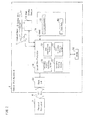
- the optical disk apparatus 1 includes an optical head 11, a disk driving device 12, a host I/F 13, an optical disk controller (recording position determining means, forming means) 14, RAM 15, and ROM 16.
- Fig. 2 is a block diagram illustrating an arrangement of essential parts of the optical disk apparatus 1 in accordance with the embodiment of the present invention.
- the optical head 11 irradiates light onto a recording surface 30 of an optical disk 3 in response to a control instruction from the optical disk controller 14, so as to read the data 40 recorded from the optical disk 3 or record the data 40 into the optical disk 3.
- the optical head 11 then sends the data 40 thus read from the optical disk 3 to the optical disk controller 14.
- the optical head 11 will be described later more specifically.
- the disk driving device 12 rotates the optical disk 3, which is a storage medium, in response to an instruction from the optical disk controller 14.
- the disk driving device 12 rotates the optical disk 3 so that the data 40 can be recorded at an intended position in a recording region of the optical disk 3 or the data 40 can be read from the recording region.
- the rotation of the optical disk 3 is executed by a spindle motor 21 included in the disk driving device 12.
- the host I/F 13 serves as an interface to the personal computer 2.
- the optical disk apparatus 1 in accordance with the present embodiment is connected to the personal computer 2 so that they can communicate with each other.
- the host I/F 13 receives a control instruction from the personal computer 2 via an I/F bus 4, and supplies the control instruction into the optical disk controller 14.
- the optical disk controller 14 carries out various controls with respect to the respective sections of the optical disk apparatus 1. More specifically, in response to the control instruction received from the personal computer 2 via the host I/F 13, the optical disk controller 14 controls the optical head 11 and the disk driving device 12 so as to read the data 40 from the optical disk 3 or record the data 40 into the optical disk 3. Further, the optical disk controller 14 carries out controls to store, into the RAM 15, the data 40 thus read from the optical disk 3 and to send the data 40 to the personal computer 2 via the host I/F 13.
- the optical disk controller 14 includes, as functional blocks, a recording position determining section (recording position determining means) 70, a sub-data forming section (forming means) 71, a data reconstruction section 72, and an error information managing section 73 (see Fig. 2 ).
- these functional blocks can be realized such that the CPU loads into the RAM 15 a program stored in the ROM 16 and executes the program.
- the sub-data forming section 71 receives, via the host I/F 13, data blocks (data) 41 into which the data is divided by the personal computer 2, and forms per data block 41 a given number of pieces of sub data 42 including pieces of element data constituting the data block 41, and parity data (reconstruction data) used for reconstructing the data block 41 (see Fig. 3 ).
- data blocks (data) 41 into which the data is divided by the personal computer 2
- parity data parity data used for reconstructing the data block 41 (see Fig. 3 ).
- the parity data it is possible to reconstruct the data block 41 based on pieces of readable element data, in a case where one of the pieces of element data becomes unreadable.
- first sub data 42a and second sub data 42b are element data
- third sub data 42c is parity data (reconstruction data).
- the sub-data forming section 71 stores these pieces of sub data 42 (the first sub data 42a, the second sub data 42b, and the third sub data 42c) into a corresponding data block storage area, which is managed in the RAM 15 per data block 41 (see Fig. 4).
- Fig. 4 illustrates one example of recording positions of the pieces of sub-data 42 in the RAM 15, in accordance with the present embodiment of the present invention.
- these pieces of sub data 42a to 42c are collectively referred to just as (pieces of) sub data 42.
- the recording position determining section 70 executes a process of calculating writing positions for the respective pieces of sub data 42 to be recorded in the optical disk 3, or a process of calculating reading positions of the respective pieces of sub data 42 recorded in the optical disk 3.
- the optical disk controller 14 records each of the first sub data 42a, the second sub data 42b, and the third sub data 42c into a physical sector of a corresponding recording layer determined by the recording position determining section 70.
- the recording position determining section 70 determines a recording position based on a data block number accompanying a reading request or a writing request sent from the personal computer 2.
- the data reconstruction section 72 Upon receiving, from the personal computer 2, instruction information for requesting a reading process of reading a target data block 41, the data reconstruction section 72 determines a reading position of the target data block 41, i.e., respective positions at which pieces of sub data 42 of the target data block 41 are written, and then reads out the pieces of sub data 42 from the respective positions. The data reconstruction section 72 reconstructs the target data block 41 from the pieces of sub data 42 thus read out, and supplies the target data block 41 to the host I/F 13 so that the target data block 41 is sent to the personal computer 2 via the I/F bus 4.
- a reading position of the target data block 41 i.e., respective positions at which pieces of sub data 42 of the target data block 41 are written, and then reads out the pieces of sub data 42 from the respective positions.
- the data reconstruction section 72 reconstructs the target data block 41 from the pieces of sub data 42 thus read out, and supplies the target data block 41 to the host I/F 13 so that the target data block 41 is sent to the personal computer 2 via
- the error information managing section 73 makes a record of sub data 42 that cannot be read properly (a reading result is "error") in the data reading process, and manages the record.
- the optical disk controller 14 reads out from the RAM 15 the first sub data 42a, the second sub data 42b, and the third sub data 42c, and then controls the optical head 11 to record these pieces of sub data 42a to 42c in the optical disk 3 in a distributed manner.
- the program for realizing the functional blocks there is stored the program for realizing the functional blocks. Further, in the ROM 16, there is stored setting information on recording of the data block 41 in the optical disk 3 and reading of the data block 41 from the optical disk 3.
- the optical disk controller 14 reads out the setting information and carries out initial settings such as positioning of the optical head 11, positioning of a focus of light irradiated from the optical head 11, and setting of light intensity. Further, in the ROM 16, there is also stored information for determining a rotational speed and the like of the optical disk 3 so that recording (writing) or reading of the data block 41 is appropriately carried out with respect to the optical disk 3 depending on performance of the optical head 11. Based on the information, the optical disk controller 14 controls the disk driving device 12.
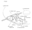
- the optical head 11 in accordance with the present embodiment includes a carriage 22, a lens 23, a mirror 24, a beam splitter 25, a laser oscillator 26, an optical sensor 27, and a focusing/tracking coil 28 (see Fig. 5 ).
- the members from the lens 23 to the focusing/tracking coil 28 are provided on the carriage 22.
- Fig. 5 is a perspective view illustrating an arrangement of the optical head 11 in accordance with the present embodiment of the present invention.
- the optical head 11 causes the laser oscillator 26 to output light in response to a control instruction from the optical disk controller 14.
- the light thus outputted is then guided into the lens 23 via the beam splitter 25 and the mirror 24.
- the lens 23 From the lens 23, the light is irradiated toward the optical disk 3.
- the light thus irradiated is focused on a recording layer of the optical disk 3 by the lens 23, and optically changes a layer material of the recording layer by heat.
- the sub data 42 is recorded in the optical disk 3.
- the sub data 42 is read from the optical disk 3
- light having lower intensity than that of the light irradiated in the recording of the sub data 42 is focused on the recording layer in which data to be read is recorded.
- Reflection light reflecting off the recording layer passes through the lens 23 and is guided into the optical sensor 27 via the mirror 24 and the beam splitter 25.
- the optical sensor 27 Upon receiving the reflection light, the optical sensor 27 converts the reflection light into an electric signal and sends the electric signal to the optical disk controller 14.
- the optical disk apparatus 1 includes the focusing/tracking coil 28 so as to perform what is called focusing that maintains the light irradiated to the optical disk 3 to be focused on a recording layer, and to perform what is called tracking that controls the light to be irradiated to a light-receiving position properly so that the light thus irradiated follows a track on the optical disk 3 accurately.
- Fig. 6 illustrates one example of a cross section structure of the optical disk 3 in accordance with the present embodiment of the present invention.
- the optical disk 3 in accordance with the present embodiment has a discoid shape.
- the optical disk 3 is provided with 4 recording layers of a first recording layer 31, a second recording layer 32, a third recording layer 33, and a fourth recording layer 34.
- a lead-in area and a lead-out area are respectively provided at an end portion of the "inner side” and an end portion of the "outer side” in a data recording area of the optical disk 3 in such a manner that the lead-in area and the lead-out area sandwich a data area in which to record the sub data 42.
- a set of the lead-in area, the data area, and the lead-out area is regarded as one session, and the sub data 42 is recordable per session.
- the lead-in area is an area in which management information provided at a headmost part of the session is managed.
- the management information is information necessary for access to the data area, such as information on tracks.
- the lead-out area is an area indicative of an end of the session.
- the optical disk 3 in accordance with the present embodiment is arranged such that each recording layer has 1 session.
- the optical disk 3 may be arranged such that a single recording layer has a plurality of session.
- the optical disk 3 illustrated in Fig. 6 is constituted by 4 recording layers, for convenience of explanation.
- the optical disk 3 may be constituted by 2 or 3 recording layers, or 4 or more recording layers.
- lead-in and lead-out areas provided in the first recording layer are respectively smaller than lead-in and lead-out areas provided in the second recording layer. That is, the lead-in and lead-out areas become larger in the order from the first recording layer to the fourth recording layer.
- the recording layer positioned farther from the recording surface 30 has a larger lead-in area and a larger lead-out area.
- the sub-data forming section 71 divides each data block 41 into a plurality of pieces of sub data 42 including parity information used for reconstructing the data block 41.
- the recording position determining section 70 determines respective recording positions for the pieces of sub data 42 so that the pieces of sub data 42 are recorded in different recording layers in a distributed manner. At this time, the recording position determining section 70 determines the respective recording positions for the pieces of sub data 42 so that they are sufficiently distanced from each other. This can prevent that plural pieces of sub data 42 among the pieces of sub data 42, formed from the same data block 41, become unreadable due to a scratch formed on the optical disk 3.
- each of the recording layers has one session and a given number of tracks (for example, 100 tracks) formed thereon. Further, it is assumed that a direction in which light emitted from the optical head 11 travels toward the recording surface 30 is regarded as a light-irradiation direction. In this case, the same-numbered tracks of the respective recording layers are placed at the same position (i.e., they overlap each other) in a projection plane viewed in the light-irradiation direction.
- the same-numbered sectors assigned on the respective recording layers are place at the same position (i.e., they overlap each other) in the projection plane. That is, the data recording position on the recording layer is managed based on track and sector, and addresses are assigned to tracks and sectors of each of the recording layers in such a manner that tracks or sectors having an identical address correspond to each other between the recording layers.
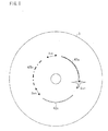
- the respective recording positions for the pieces of sub data 42 sufficiently distanced from each other means that the respective recording positions for the pieces of sub data 42 are sufficiently distanced from each other in a projection plane of the optical disk 3 viewed in the light-irradiation direction, so that not all the pieces of sub data 42 are affected by a scratch. That is, in the optical disk apparatus 1, the pieces of sub data 42 recorded in the respective recording layers are recorded in the same-numbered tracks of the respective recording layers in a distributed manner such that they are away from each other by a given distance in the projection plane (see Fig. 1 and Fig. 7 ). Fig.
- Fig. 1 illustrates the present embodiment of the present invention, specifically illustrating one example of the respective recording positions for the pieces of sub data 42 in the projection plane of the optical disk 3 viewed from the light-irradiation direction.
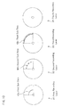
- Fig. 7 illustrates the present embodiment of the present invention, separately illustrating the recording layers so as to show where each of the recording positions for the pieces of data 42, illustrated in Fig. 1 , is located on a corresponding recording layer.
- the first sub data (element data) 42a, the second sub data (element data) 42b, and the third sub data (parity data) 42c are recorded in the respective recording layers in a distributed manner so that they are away from each other by at least a given distance and do not overlap each other.
- the first sub data 42a, the second sub data 42b, and the third sub data 42c are recorded, in a distributed manner, into respective tracks n in the first recording layer 31, the second recording layer 32, and the third recording layer 33, respectively.
- Fig. 8 illustrates the present embodiment of the present invention, specifically illustrating one example of a positional relationship between the respective recording positions for the pieces of sub data 42 and a position of the scratch formed on the protection layer, in the projection plane of the optical disk 3 viewed from the light-irradiation direction.
- the pieces of sub data 42 are distanced from each other by at least 2 cm in the projection plane.
- the scratch does not cause 2 or more pieces of sub data 42 to have reading errors.
- the optical disk apparatus 1 specifies different sectors of the same-numbered tracks on different recording layers and records the pieces of sub data 42 into the different sectors, respectively.
- the pieces of sub data 42 do not overlap each other in the projection plane of the optical disk 3, and it is possible to make the pieces of sub data 42 away from each other by at least a given distance.
- the optical disk apparatus 1 is arranged to carry out the recording of the pieces of sub data 42 into the different sectors thus specified in the different recording layers, as described above.
- the optical disk apparatus 1 is not limited to the arrangement, and may be so arranged to record the pieces of sub data 42 into different-numbered tracks in the different recording layers in such a manner that the pieces of sub data 42 are away from each other by at least a given distance in the projection plane (for example, see Fig. 9 ).
- the optical disk apparatus 1 may carry out data recording in a distributed manner such that (i) the first sub data 42a is recorded into a sector p on a track a of the first recording layer 31, (ii) the second sub data 42b is recorded into a sector q on a track b of the second recording layer 32, and (iii) the third sub data 42c is recorded into a sector r on a track c of the third recording layer 33 (see Fig. 10 ).
- Fig. 9 illustrates the present embodiment of the present invention, specifically illustrating an example of the recording positions for the pieces of sub data 42, in the projection plane of the optical disk 3 viewed from the light-irradiation direction.
- Fig. 10 illustrates the present embodiment of the present invention, separately illustrating the recording layers to show where each of the recording positions for the pieces of sub data 42, illustrated in Fig. 9 , is located on a corresponding recording layer.
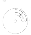
- the pieces of sub data 42 are recorded into respective tracks so that the respective tracks are distanced from each other by at least 2 cm in consideration of reconstruction of the data block 41 (see Fig. 11 ). That is, the pieces of sub data 42 have such a positional relationship that they are recorded away from each other by at least 2 cm in the projection plane. With the arrangement, even in a case where a 2-cm scratch is formed on the protection layer on the recording surface 30, the scratch does not cause 2 or more pieces of sub data 42 to have reading errors. Fig.
- FIG. 11 illustrates the present embodiment of the present invention, specifically illustrating one example of a positional relationship between the respective recording positions for the pieces of sub data 42 and a position of the scratch formed on the protection layer, in the projection plane of the optical disk 3 viewed in the light-irradiation direction.
- the given distance between the pieces of sub data 42 is not limited to 2 cm, and may be determined according to an allowable range, in the optical disk 3, of a size of a scratch, within which range the data block 41 can be reconstructed.
- the recording positions for the pieces of sub data 42 are sectors on the different-numbered tracks on the different recording layers or different sectors on the same-numbered tracks on the different recording layers.
- the recording positions for the pieces of sub data 42 are not limited to the above arrangements, and may be different sectors on different-numbered tracks on the same recording layer provided that the respective recording positions for the pieces of sub data 42 are away from each other by the aforementioned given distance.
- the sub-data recording position (recording position for sub data) can be specified based on a sector number and a track number as explained below, more specifically.
- the optical disk apparatus (information processing apparatus) 1 is arranged such that the pieces of sub data 42 are recorded away from each other by a given distance in the projection plane, as described above.
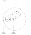
- the following describes how to specify the recording positions for the pieces of sub data 42 in the optical disk apparatus 1 according to the present embodiment, more specifically, how the recording position determining section 70 finds the recording positions for the pieces of sub data 42, with reference to Fig. 12.
- Fig. 12 illustrates the present embodiment of the present invention, specifically illustrating a sub-data recording position in the projection plane of the optical disk 3 and how to specify the sub-data recording position.
- the management information recorded in the lead-in area includes information on the number of tracks (for example, 100 tracks) in each recording layer and information on a distance (for example, 10 cm) between an innermost track and an outermost track in each recording layer. From these pieces of information, a distance between tracks can be found. Accordingly, it is possible to specify, in the projection plane, a shortest distance ⁇ between the pieces of sub data 42 recorded in respective sectors on different tracks.
- a positional relationship between the pieces of sub data 42 to be recorded i.e., a distance ( ⁇ ) between the pieces of sub data 42, based on (i) recording start angles and recording end angles of the pieces of sub data 42 each from a reference position (0 degree) and (ii) the track number of the tracks in which to record the pieces of sub data 42, where a radius at a given position in the projection plane of the optical disk 3 is taken as the reference position (0 degree).
- the positional relationship between the pieces of sub data 42 to be recorded i.e., the distance ( ⁇ ) between the pieces of sub data 42, based on the number of sectors present between the pieces of sub data 42 and the track number of the tracks in which to record the pieces of sub data 42.
- the positional relationship between the pieces of sub data 42 i.e., the distance between the pieces of sub data 42 to be recorded is specified based on the angles of the pieces of sub data 42 from the reference position or the number of sectors present between the pieces of sub data 42, even if the angels are the same or the number of sectors present between the pieces of sub data 42 is the same, the distance between the pieces of sub data 42 becomes different between a case where the tracks in which to record the pieces of sub data 42 are close to a center of the optical disk 3 and a case where the tracks in which to record the pieces of sub data 42 are close to the outer circumference of the optical disk 3.
- the optical disk apparatus 1 changes the angles from the reference position or the number of sectors, specified as the distance between recording positions for the pieces of sub data 42, depending on a distance, in the projection plane, from a center of the optical disk 3 to a respective of the tracks in which to record the pieces of sub data 42. That is, the shorter the distance from the center of the optical disk 3 to the respective of the tracks is, the larger the angles of the pieces of sub data 42 from the reference position is set to be or the larger the number of sectors between the pieces of sub data 42 is set to be.
- the optical disk apparatus 1 can change the number of sectors defining the distance between the pieces of sub data 42 or the angles of the pieces of sub data 42 from the reference position which define the distance between the pieces of sub data 42, depending on the distance from the center of the optical disk 3 to a respective of the tracks in which to record the pieces of sub data 42.
- the management information recorded in the lead-in area includes information on the number of tracks in each of the recording layers and information on the distance from the innermost track to the outermost track in each of the recording layers.
- another arrangement may be also adoptable.
- the management information recorded in the lead-in area may include sector position information for specifying sector positions in each of the recording layers.
- the optical disk apparatus 1 may calculate the distance between the innermost track and the outermost track by detecting a boundary between the lead-in area and the data area and a boundary between the data area and the lead-out area in each of the recording layer of the optical disk 3.
- the recording position for the sub data 42 can be determined such that the recording position determining section 70 carries out the following calculation.
- a radius of the optical disk 3 is 12 cm
- a length of the data area in a direction of the radius of the optical disk 3 is 10 cm
- a maximum size of a scratch, which is allowable for reconstruction of the data block 41 is 2 cm.
- the optical disk 3 includes 100 tracks in the data area in each of the recording layers, and each of the tracks includes 12 sectors.
- the optical disk 3 includes 4 recording layers, and the recording layers are provided so as to be laminated on one another in the light-irradiation direction.
- Information indicating that the length of the data area is 10 cm and information indicating that the number of tracks is 100 and the number of sectors is 12 are preliminarily included in the management information recorded in the lead-in area.
- a track width is 1 mm as calculated from the length of the data area and the number of tracks.
- the number of physical sectors is 1200 per recording layer (i.e., 100 tracks ⁇ 12 sectors, sector numbers are from 0th to 1199th in each of the recording layers). That is, the total number of the physical sectors of the 4 recording layers is 4800.
- 3 pieces of sub data 42 are formed from the data block 41 and recorded in a distributed manner. That is, for access request to a single data block 41, 3 pieces of sub data 42 are recorded.
- a physical storage capacity of one sector in each of the recording layers is 512 bytes
- a logical storage capacity of the single data block 41 is 1024 bytes/sector because one of the 3 pieces of sub data 42 is parity data.
- the track width is 1 mm. Therefore, in order to record the pieces of sub data 42 away from each other by at least 2 cm, it is necessary to record the pieces of sub data 42 away from each other by at least 20 tracks.
- recording of a data block of a data block number "0" is carried out by use of the first, second, and third recording layers according to the expression (1).
- the sector addresses of sectors in which to record respective pieces of sub data 42, which are constituents of the data block of the data block number "0" are determined according to the expression (2) as follows: a physical sector number of the sector to be used in the first recording layer 31 is 0; a physical sector number of the sector to be used in the second recording layer 32 is 240; and a physical sector number of the sector to be used in the third recording layer 33 is 480.
- a first piece of sub data 42 is written into a sector whose physical sector number is 0, which is located in the innermost track, respective first pieces of sub data for the second recording layer 32, the third recording layer 33, and the fourth recording layer 34 are not written into respective innermost tracks of the second to fourth recording layers (32, 33, 34). This is because pieces of sub data are written into respective tracks of the recording layers such that the respective tracks are distanced from each other by 20 tracks.
- the expression (2) is used for finding a physical sector in each recording layer in a case where pieces of sub data 42 are recorded in respective recording layers such that respective tracks in which to record the pieces of sub data 42 are distanced from each other by at least 2 cm in the projection plane.
- the physical sector numbers according to the following expression (3) which allow the pieces of sub data 42 to be recorded away from each other by at least 2 cm, in the projection plane, on the same-numbered tracks in the respective recording layers.
- the pieces of sub data 42 are recorded in the respective recording layers so that respective sectors in which to record the pieces of sub data 42 are distanced from one another by 3 sectors, i.e., by a central angle of 90° in the recording surface 30.
- Physical Sector Number Data Block Number / 12 ⁇ 12 + Data Block Number + Recording Layer Number - 1 ⁇ 3 % 12
- the recording position determining section 70 can determine the recording positions for the pieces of sub data by use of the addresses of the tracks or the sectors so that the recording positions do not overlap each other. This allows the optical disk apparatus 1 according to the present embodiment to easily determine the sub-data recording positions.
- Fig. 13 is a flowchart illustrating a process flow of the writing process and reading process of the data block 41, carried out by the optical disk apparatus 1, in accordance with the present embodiment of the present invention.
- the optical disk controller 14 controls the optical head 11 and the disk driving device 12 to carry out initial operations (Step S11, hereinafter, referred to just as S11).
- the optical disk controller 14 controls the optical head 11 and the disk driving device 12 to execute self-tests of testing whether the optical head 11 and the driving device 12 themselves operate normally, and controls the optical head 11 to move to an initial position.
- the optical disk controller 14 instructs the disk driving device 12 to rotate the optical disk 3 (S12).
- the optical disk apparatus 1 is ready for carrying out the writing process or the reading process of the data block 41. Subsequently, the optical disk controller 14 checks whether or not the host I/F 13 receives instruction information from the personal computer 2 (S13).
- the optical disk controller 14 determines that the host I/F 13 receives the instruction information ("YES" in S13)
- the optical disk controller 14 advances its process to S14.
- the optical disk controller 14 receives the instruction information from the host I/F 13.
- the optical disk controller 14 carries out the process of S13 again until any instruction information is entered from the personal computer 2.
- the optical disk controller 14 After receiving the instruction information in S14, the optical disk controller 14 determines whether or not the instruction information is an instruction to write a data block 41 (S15), or determines whether or not the instruction information is an instruction to read a data block 41 (S16). More specifically, in a case of YES in the step S15, the optical disk controller 14 carries out a writing process (S17).
- the process of the optical disk controller 14 proceeds to S16, and the optical disk controller 14 determines whether or not the instruction information is an instruction to read a data block 41. In a case of YES in S16, the optical disk controller 14 carries out a reading process (S18). In a case of NO in S16, the process of the optical disk controller 14 returns to S13 and the optical disk controller 14 waits until next instruction information is entered.
- the process of the optical disk controller 14 After the writing process in S17 or the reading process in S18 is executed, the process of the optical disk controller 14 returns back to S13 and waits for next instruction information. In this way, the optical disk controller 14 waits until the instruction information is entered from the personal computer 2, and repeatedly carries out the reading process or the writing process in accordance with the instruction information.
- the optical disk controller 14 determines, in S15, whether or not the instruction information received from the personal computer 2 is a request for writing, and then determines, in S16, whether or not the instruction information is a request for reading.
- the order of these steps is not limited to this. That is, the optical disk controller 14 may be so arranged to initially determine whether the instruction information received from the personal computer 2 is a request for reading, and then determine whether or not the instruction information is a request for writing.
- Fig. 14 is a flowchart illustrating a flow of the writing process in the optical disk apparatus 1 in accordance with the present embodiment of the present invention.
- the optical disk controller 14 determines that the instruction information received from the personal computer 2 is a request for writing a data block 41 into the optical disk 3, the optical disk controller 14 receives via the host I/F 13 a target data block 41 to be written from the personal computer 2 (S21).
- the optical disk controller 14 sends the target data block 41 thus received to the sub-data forming section 71.
- the sub-data forming section 71 forms pieces of sub data 42 from the target data block 41 (S22).
- 3 pieces of sub data 42 are formed as follows: 2 pieces of element data that are constituents of the target data block 41; and reconstruction data including parity data for reconstructing the target data block 41 even if either one of the 2 pieces of element data is lost.
- the sub-data forming section 71 stores the pieces of sub data 42 into a corresponding sub-data storage area in the RAM 15.
- the recording position determining section 70 carries out the calculation as described in "Specifying of Sub-data Recording Position", and determines a writing position (a recording layer and a physical sector number) (S23).
- the optical disk controller 14 controls the optical head 11 to move to the determined writing position. Then, the optical disk controller 14 sends, to the optical head 11, information of the sub data 42 to be written at that position, and instructs the optical head 11 to write the sub data 42 therein.
- the sub data 42 is written into the optical disk 3 (S24).
- the optical disk controller 14 determines whether or not writing of all the pieces of sub data 42 formed from the target data block 41 is completed (S25). If the writing of all the pieces of sub data 42 has not been completed yet (NO in S25), the optical disk controller 14 carries out the processes of S23 and S24 again. When the writing of all the pieces of sub data 42 formed from the target data block 41 is completed (YES in S25), the optical disk controller 14 ends the writing process.
- Fig. 15 is a flowchart illustrating a flow of the reading process in the optical disk apparatus 1 in accordance with the present embodiment of the present invention.
- the data reconstruction section 72 determines a reading position of the target data block 41 in accordance with the instruction from the personal computer 2 (S31).
- the data reconstruction section 72 carried out the calculation as described in "Specifying of Sub-data Recording Position" so that the data reconstruction section 72 can identify respective recording positions of the pieces of sub data.
- the optical disk controller 14 instructs the optical head 11 to move to a corresponding position to the reading position.
- the optical head 11 moves to the corresponding position to the reading position of the sub data 42, and irradiates light thereto so as to read the sub data 42 by irradiating light (S32). Then, the optical head 11 sends a reading result to the optical disk controller 14.
- the optical disk controller 14 determines whether or not any error occurs in the sub data 42 thus read (S33). In a case where the optical disk controller 14 determines that an error occurs in the reading result of the sub data 42 (YES in S33), the error information managing section 73 records that the sub data 42 causes an error at the time of reading (S34). That is, error information 18 is recorded in the RAM 15.
- the error information 18 indicates sub data having an error by marking it with a flag "1" so that which one of the first sub data 42a, the second sub data 42b, and the third sub data 43 causes an error at the time of reading can be identified (see Fig. 16).
- Fig. 16 illustrates an example of the error information 18 in accordance with the present embodiment of the present invention.
- the optical disk controller 14 determines whether or not reading of all pieces of sub data 42 is completed (S35). In a case where an error is found in the reading result of the read sub data 42 (YES in S33), the error information managing section 73 records the error information 18 into the RAM 15 (S34). Then, the optical disk controller 14 determines whether or not the reading of all the pieces of sub data 42 is completed (S35). In a case where the reading of all the pieces of sub data 42 has not been completed yet (NO in S35), the optical disk controller repeatedly carries out the processes from S31 to S34 until all the pieces of sub data 42 are read.
- the data reconstruction section 72 in the optical disk controller 14 refers to the error information 18 recorded in the RAM 15 and determines whether or not any error is found (S36).
- the data reconstruction section 72 determines that no error occurs in the reading results of the pieces of sub data 42 (NO in S36), the data reconstruction section 72 reconstructs the target data block 41 from given pieces of sub data 42 (the first sub data 42a and the second sub data 42b) exclusive of the parity data (S37). In contrast, in a case where an error occurs in the reading results of the pieces of sub data 42 (YES in S36), the data reconstruction section 72 reconstructs the data block 41 from usable piece(s) of sub data 42 in which no error is found (S38). For example, in a case where an error occurs in the reading result of the first sub data 42a, the first sub data 42a is reconstructed from the second sub data 42b and the third sub data 42c, which is parity data. Then, the target data block 41 is reconstructed from the first sub data 42a thus reconstructed and the second sub data 42b (S38).
- the optical disk controller 14 sends via the host I/F 13 the reconstructed data block 41 to the personal computer 2.
- the optical disk apparatus 1 carries out the reading process of reading the data block 41.
- the recording position determining section 70 determines a writing position for the sub block 42 that is formed by the sub-data forming section 71 from the data block 41. Then, the optical disk controller 14 controls the optical head 11 and the disk driving device 12 to write the sub data 42 into the optical disk 3. Further, in the above arrangement, upon receiving instruction information on the reading process from the personal computer 2, the recording position determining section 70 determines a reading position of the sub data 42. Then, the optical disk controller 14 controls the optical head 11 and the disk driving device 12 to read the sub data 42 from the optical disk 3. Subsequently, the data reconstruction section 72 reconstructs the data block 41 and sends it to the personal computer 2.
- Fig. 17 is a block diagram illustrating an arrangement of essential parts of the optical disk system 50 in accordance with the present embodiment of the present invention.
- the optical disk system 50 includes: a personal computer 61, which carries out various control instructions on data writing (writing process) and data reading (reading process) with respect to the optical disk 3; and an optical disk apparatus 51, which writes a data block 41 into the optical disk 3 in accordance with a control instruction from the personal computer 61 or reads a data block 41 from the optical disk 3 in accordance with a control instruction from the personal computer 61.
- the personal computer 61 and the optical disk apparatus 51 are communicably connected to each other via an I/F bus 4.
- the personal computer 61 includes: a CPU (recording position determining means , forming means) 62, which carries out various controls of the personal computer 61; a personal computer I/F (PC ⁇ I/F) 63, which serves as an interface to the optical disk apparatus 51; and a storage device 64 in which an application program for realizing various controls of the personal computer 61 and the like are stored.
- a CPU recording position determining means , forming means
- PC ⁇ I/F personal computer I/F
- storage device 64 in which an application program for realizing various controls of the personal computer 61 and the like are stored.
- the optical disk apparatus 51 includes: an optical disk controller 54, which controls the writing process or reading process of the data block 41, carried out by the optical disk apparatus 51 with respect to the optical disk 3; an optical head 11 for reading sub data 42 of the data block 41 from the optical disk 3 or for writing sub data 42 of the data block 41 into the optical disk 3, in accordance with a control instruction from the optical disk controller 54; a disk driving device 12 for rotating the optical disk 3 in accordance with a control instruction from the optical disk controller 54; and a host I/F 13, which serves as an interface to the personal computer 2.
- an optical disk controller 54 which controls the writing process or reading process of the data block 41, carried out by the optical disk apparatus 51 with respect to the optical disk 3
- an optical head 11 for reading sub data 42 of the data block 41 from the optical disk 3 or for writing sub data 42 of the data block 41 into the optical disk 3, in accordance with a control instruction from the optical disk controller 54
- a disk driving device 12 for rotating the optical disk 3 in accordance with a control instruction from the optical disk controller 54
- the optical disk system 50 illustrated in Fig. 17 is different from the optical disk apparatus 1 illustrated in Fig. 2 in that: (i) in the case of the optical disk 50, the CPU 62 of the personal computer 61 includes a recording position determining section 70, a sub-data forming section 71, a data reconstruction section 72, and an error information managing section 73, while they are provided in the optical disk controller 14 in the case of the optical disk apparatus 1 (see Fig. 2 ); (ii) the CPU 62 further includes a dividing section 201 in addition to the above sections; and (iii) the CPU 62 carries out processes (a) through (f) described below.
- the recording position determining section 70, the sub-data forming section 71, the data reconstruction 72, and the error information managing section 73, which are provided in the CPU 62, are respectively the same as the recording position determining section 70, the sub-data forming section 71, the data reconstruction section 72, and the error information managing section 73, which are provided in the optical disk controller 14 illustrated in Fig. 2 . Therefore, explanations about these sections are omitted and they have the same reference signs as those in Fig. 2 .
- the processes (a) through (f) carried out by the CPU 62 are as follows:
- the CPU 62 stores, in a data block storage area in the storage device 64, the pieces of sub data 42 thus formed, in the order of combination of the pieces of sub data 42 (i.e., the first sub data 42a, the second sub data 42b, the third sub data 42c) (see Fig. 18 ).
- the pieces of sub data 42 are stored in the data block storage area per data block 41.
- Fig. 18 illustrates one example of recording positions of pieces of sub data 42 in the storage device 64 in accordance with the present embodiment of the present invention.
- the storage device 64 is provided with (i) an area (other use area) for various processes, exclusive of the writing process or the reading process with respect to the optical disk 3, carried out by the personal computer 61, (ii) an area in which to store an application program to be executed, and (iii) a data block storage area.
- the optical disk apparatus 51 can be realized by a conventional optical drive provided that the optical drive includes the host I/F 13 for communicating with the personal computer 61.
- the host I/F 13 is not necessarily an I/F only for the optical disk, but may be a network I/F such as Ethernet.
- the optical disk apparatus 1 or the optical disk system 50 in accordance with the present embodiment is so arranged that pieces of sub data 42 are recorded at respective recording positions in different recording layers in a distributed manner such that the respective recording positions do not overlap each other in a projection plane of the optical disk viewed in the light-irradiation direction in which the irradiated light travels toward the recording surface 30.
- the pieces of sub data 42 are recorded away from each other by at least a given distance in the projection plane. This makes it possible to prevent that a scratch formed on a protection layer of the optical disk 3 damages 2 or more pieces of sub data 42.
- the pieces of sub data 42 includes (a) pieces of element data formed by dividing a data block 41 into the pieces, and (b) reconstruction data as parity data, which enables reconstruction of the data block 41 even if any one of the pieces of element data is lost.
- the above arrangement can prevent such a problem that the scratch on the protection layer causes an error in reading results of a plurality of sub data 42 and renders the data block 41 unreconstructible.
- either of the optical disk apparatus 1 and the optical disk system 50 according to the present embodiment can improve reliability of reconstruction of data 40 in which data loss occurs, in a case where the data 40 is recorded into a plurality of recording layers of the optical disk 3.
- the optical disk apparatus 1 and the optical disk system 50 in accordance with the present embodiment are arranged so as to manage whether any error occurs in reading results of the pieces of sub data 42 at the time of reading the data 40 from the optical disk 3. This makes it possible to figure out whether or not any scratch is formed on the optical disk 3.
- the optical disk apparatus 1 or the personal computer 2 may include a display section (not shown) so as to display on the display section a message indicating that the optical disk 3 is damaged in such a case where the scratch is formed on the optical disk 3. With this arrangement, a user can be notified that the optical disk 3 is damaged so that the user can read the data 40 from the damaged optical disk 3 before the data 40 becomes unreconstructible, and then record the data 40 into another optical disk 3.
- pieces of sub data 42 constituting a data block 41 are recorded in the same-numbered tracks in respective recording layers such that they are recorded away from each other by at least a given distance (for example, 2 cm) in the projection plane, or alternatively they are recorded in different-numbered tracks in the respective recording layers such that they are recorded away from each other by at least a given distance (for example, 2 cm) in the projection plane.
- the recording of the pieces of sub data 42 is not necessarily carried out in accordance with the above arrangement, provided that the pieces of sub data 42 are recorded away from each other by at least a given distance in the projection plane. Further, the pieces of sub data 42 are not necessarily recorded in different layers in a distributed manner, and may be recorded in the same recording layer (e.g., the first recording layer in Fig. 19 ) in such a manner that the pieces of sub data 42 are recorded away from each other by at least a given distance.
- Fig. 19 illustrates the present embodiment of the present invention, separately illustrating recording layers to show where each sub-data recording position is located on a corresponding recording layer.
- the number of recording layers may vary depending on the arrangement of the optical disk 3, and the optical disk 3 may include 2, 3, or 4 or more recording layers.
- either of the optical disk apparatus 1 and the optical disk system 50 in accordance with the present embodiment is preferably arranged such that it can check how many recording layers the optical disk 3 has, before the writing process or reading process of the data block 41 is carried out with respect to the optical disk 3.
- either of the optical disk apparatus 1 and the optical disk system 50 in accordance with the present embodiment may be so arranged that it can detect the number of recording layers in the optical disk 3 by focusing.
- either of the optical disk apparatus 1 and the optical disk system 50 may be so arranged that the number of recording layers are recorded into a lead-in area of the optical disk 3 in advance and the optical disk apparatus 1 or the optical disk system 50 reads out the number of recording layers therefrom. The checking of the number of recording layers is carried out before S12.
- the optical disk apparatus 1 or the optical disk system 50 in accordance with the present embodiment is arranged such that the pieces of sub data 42 include (i) pieces of element data into which a data block 41 are broken and (ii) reconstruction data including parity information obtained from the pieces of data.
- the pieces of sub data 42 are not limited to these pieces of data, and may be data of the data bock 41 and reconstruction data, which is a copy of the data.
- the track address and the sector address i.e., the track number and the sector number are assigned in a corresponding manner in the first recording layer 31, the second recording layer 32, the third recording layer 33, and the fourth recording layer 34. That is, in these recording layers, sectors having the same sector number overlap each other in the projection plane of the optical disk 3 and tracks having the same track number also overlap each other in the projection plane of the optical disk 3.
- the recording position determining section 70 calculates respective recording layer numbers, respective sector numbers, and respective track numbers for pieces of sub data 42 so that respective recording positions for the pieces of sub data 42 do not overlap each other in the projection plane.
- the pieces of sub data 42 are accordingly recorded in the respective recording positions.
- FIG. 20 illustrates an arrangement of essential parts of an optical disk apparatus 101 in accordance with another embodiment (Embodiment 2) of the present invention.
- the optical disk apparatus 101 includes an optical head 11, a disk driving device 12, a host I/F 13, an optical disk controller 114, RAM 115, and ROM 16.
- the optical disk apparatus 101 is different from the optical disk apparatus 1 (see Fig. 2 ) in that the optical disk controller 114 includes, as functional blocks, a format setting section 74 in addition to a sub-data forming section 71, a data reconstruction section 72, an error information managing section 73. Further, the optical disk apparatus 101 is different from the optical disk apparatus 1 in that recorded into the RAM 115 is writing start position information 19 in addition to error information 18 and sub data 42.
- the format setting section 74 resets the assignment of the track number and the sector number in the optical disk 3. Further, the writing start position information 19 is information indicative of a writing start position set by the format setting section 74 in each recording layer.
- the same members as the members provided in the optical disk apparatus 1 illustrated in Fig. 2 have the same reference signs as those in Fig. 2 , and explanations thereof are omitted.
- the optical disk apparatus 101 according to Embodiment 2 is so arranged to record the sub data 42 sequentially from a position having a smaller address value set in each recording layer, i.e., in the order from a position whose track number is 0 and whose sector number is 0. That is, the position whose track number is 0 and whose sector number is 0 is set as a data writing start position in each recording layer.
- the optical disk apparatus 101 sets (i) an inner circumference in a first recording layer 31 of the optical disk 3 to a track number "0" and a sector number "0" of the first recording layer 31, and (ii) a position, in the second recording layer 32, shifted by a given distance from the inner circumference toward an outer circumference of the optical disk 3, to a track number "0" and a sector number "0" of the second recording layer 32.
- a position, in the third recording layer 33, which is shifted by the given distance from the position at the track number "0" and the sector number "0" in the second recording layer 32 toward the outer circumference is set to a track number "0" and a sector number "0” in the third recording layer 33.
- a position, in the fourth recording layer 34, which is shifted by the given distance from the position at the track number "0" and the sector number "0" in the third recording layer 33 toward the outer circumference is set to a track number "0” and a sector number "0” in the fourth recording layer 34.
- Fig. 21 illustrates an exemplary setting of a track number "0” and a sector number "0” in each of the recording layers in accordance with Embodiment 2 of the present invention.
- the given distance is determined according to requirements for reconstruction of data 40.
- a distance between a recording position (writing start position) for first sub data 42a and a recording position (writing start position) for second sub data 42b, and a distance between the recording position (writing start position) for the second sub data 42b and a recording position (writing start position) for third sub data 42c should be at least 2 cm.
- the format setting section 74 sets the writing start position in each of the recording layers in a data area on the optical disk 3 appropriately, it is then determined into which recording layer each of the pieces of sub data 42 is to be recorded. Then, information (writing start position information 19) on the writing start positions determined for the pieces of sub data 42 is stored in the RAM 115. That is, the writing start position information 19 shown in Fig. 20 only indicates a physical sector number and a recording layer number of a recording position, on the optical disk 3, in which to write the first sub data 42a among the pieces of sub data 42 formed from the data block 41. In contrast, the writing start position information 19 illustrated in Fig.
- 21 includes (i) numbers (recording layer numbers) of recording layers in which to write the respective pieces of sub data 42 formed from the data block 41, and (ii) track numbers and sector numbers (track “0" and sector “0") each indicative of a writing start position in each of the recording layers (see Fig. 22 ).
- the optical disk controller 114 controls the optical head 11 and the disk driving device 12 to write each of the first sub data 42a, the second sub data 42b, and the third sub data 42c into a corresponding recording layer at a corresponding writing start position.
- first sub data 42a, second sub data 42b, and third sub data 42c of the another data block 41 are recorded, respectively, at recording positions subsequent to those of the first sub data 42a, the second sub data 42b, and the third sub data 42c which have been already recorded.
- the pieces of sub data 42 of the data blocks 41 are recorded in the successive manner as above, so that first sub data 42a, second sub data 42b, and third sub data 42c formed from the same data block 41 are always recorded in different recording layers at respective positions that are away from each other by a given distance in the projection plane of the optical disk 3.
- the optical disk apparatus 101 (information processing apparatus) in accordance with Embodiment 2 may be also arranged as below. That is, the optical disk apparatus 101 in accordance with Embodiment 2 records a data block 41 by irradiating light with respect to an optical disk 3 including a plurality of recording layers (a first recording layer 31, a second recording layer 32, and a third recording layer) in which to store the data block 41.
- an optical disk 3 including a plurality of recording layers (a first recording layer 31, a second recording layer 32, and a third recording layer) in which to store the data block 41.
- the optical disk apparatus 101 includes: a sub-data forming section 71 for forming, from a single data block 41 to be recorded, element data constituting the data block 41 and parity data (reconstruction data) for reconstructing data in a case where the element data becomes unreadable; and a format setting section 74 for carrying out setting of a track address and a sector address indicative of a writing start position for the element data or the parity data (reconstruction data) in a corresponding recording layer.
- the sub-data forming section 71 carries out, per recording layer, the setting of the track address and the sector address indicative of the writing start position for the element data or the parity data, so that the element data and the parity data are recorded at different positions in a projection plane of the optical disk 3 viewed in the light-irradiation direction.
- the sub-data forming section 71 forms, from a single data block 41, element data and parity data for reconstructing the data block 41, as sub data 42. Therefore, even in a case where the element data is unreadable, it is possible to reconstruct data recorded in the optical disk 3 by use of the parity data.
- the optical disk apparatus 101 since the optical disk apparatus 101 includes the format setting section 74, it is possible to set addresses indicative of recording start positions for the element data and the parity data so that the element data and the parity data are recorded at different positions that do not overlap each other in the projection plane of the optical disk 3. In a case where the element data and the parity data are recorded into different recording layers at respective positions that overlap each other in the projection plane, there may occur a problem that both of the element data and the parity data become unreadable due to a scratch formed on the optical disk 3a. However, the above arrangement makes it possible to prevent such a problem. With the arrangement, it is possible to improve reliability of reconstruction of a data block 41 recorded in the optical disk 3 in a case where data loss occurs in the recorded data block 41.
- an information processing apparatus control method according to the present invention includes the following steps.
- an information processing apparatus of the present invention is an information processing apparatus for recording data into an optical disk including a plurality of recording layers in which to record data, by irradiating light thereto.
- the information processing apparatus of the present invention includes: forming means for forming, from a single piece of data to be recorded, element data constituting the single piece of data and reconstruction data for reconstructing the single piece of data in a case where the element data becomes unreadable; and recording position determining means for determining respective recording positions for the element data and the reconstruction data, which are formed by the forming means from the single piece of data, so that the element data and the reconstruction data are recorded at the respective recording positions in different recording layers.
- the recording position determining means determines the respective recording positions for the element data and the reconstruction data such that the respective recording positions do not overlap each other in a projection plane of the optical disk viewed in a light-irradiation direction in which the irradiated light travels.
- the above arrangement allows the information processing apparatus according to the present invention to advantageously improve reliability of data reconstruction in a case where data loss occurs in recorded data in an optical disk in which data is recordable in a plurality of layers.
- the information processing apparatus may be arranged such that: each of the recording positions for data is managed according to a track and a sector in each of the plurality of recording layers; addresses are assigned to tracks in a corresponding manner in the plurality of recording layers and addresses are assigned to sectors in a corresponding manner in the plurality of recording layers; and the recording position determining means determines the respective recording positions for the element data and the reconstruction data, which recording positions do not overlap each other in the projection plane, so that the element data and the reconstruction data are recorded into respective tracks or sectors of different addresses in the different recording layers.
- the information processing apparatus may be arranged such that: the recording position determining means specifies the number of sectors or tracks for an interval between the respective recording positions for the element data and the reconstruction data in the projection plane so that the element data and the reconstruction data are recorded into the respective tracks or sectors of different addresses in the different recording layers.
- addresses are assigned to tracks in a corresponding manner in the plurality of recording layers and addresses are assigned to sectors in a corresponding manner in the plurality of recording layers, it is possible to use common track numbers and common sector numbers to specify a recording position in each of the plurality of recording layers.
- the recording position determining means can determine, by specifying a track or sector, each of the recording positions for the element data and the reconstruction data so that the recording positions do not overlap each other in the projection plane. Therefore, it is possible to easily determine the recording positions for the element data and the reconstruction data.
- the information processing apparatus may be arranged such that: the forming means forms, from the single piece of data to be recorded, the element data, which includes pieces of element data, and the reconstruction data, which is capable of reconstructing the single piece of data from readable pieces of element data among the pieces of element data in a case where any one of the pieces of element data becomes unreadable; an allowable size of a scratch to be formed on a recording surface of the optical disk, which is a surface that receives the irradiated light for recording the single piece of data therein, is set within a range in which the single piece of data is reconstructible; and the recording position determining means determines recording positions for the pieces of element data and the reconstruction data by specifying (a) the number of sectors or tracks for an interval between the recording positions for the pieces of element data and (b) the number of sectors or tracks for an interval between the recording positions for a respective of the pieces of element data and the reconstruction data so that the recording positions for the pieces of element data and the reconstruction data are distance
- the recording position determining means can specify the number of sectors or tracks for an interval between the recording positions for the pieces of element data and the number of sectors or tracks for an interval between the recording positions for a respective of the pieces of element data and the reconstruction data so that the recording positions are distanced from each other by at least the allowable size of the scratch thus set.
- the information processing apparatus may be arranged such that: the recording position determining means changes the number of sectors specified for (a) the interval between the recording positions for the pieces of element data and (b) the interval between the recording positions for a respective of the pieces of element data and the reconstruction data, depending on a distance, in the projection plane, from a center of the optical disk to a respective of tracks in which to record the pieces of element data and the reconstruction data.
- a length of a track in the vicinity of the center of the optical disk is different from that of a track in the vicinity of a circumference of the optical disk.
- the pieces of element data and the reconstruction data are recorded away from each other by a given number of sectors.
- a distance between the pieces of element data or a distance between a respective of the pieces of element data and the reconstruction data becomes shorter in a case where they are recorded in the track in the vicinity of the center of the optical disk than in a case where they are recorded in the track in the vicinity of the circumference of the optical disk.
- the number of sectors for the interval between the pieces of element data or the interval between the respective of the pieces of element data and the reconstruction data can be changed. This makes it possible to determine appropriate recording positions for the element data and the reconstruction data by specifying the number of sectors in each of the recording layers of the optical disk.
- the information processing apparatus may be arranged such that: the forming means forms, from the single piece of data to be recorded, the element data, which includes a plurality of pieces of element data into which the single piece of data is broken, and the reconstruction data, which includes parity information obtained from the plurality of pieces of element data.
- the information processing apparatus may be arranged such that: the forming means forms, from the single piece of data to be recorded, the element data, which is the single piece of data itself, and the reconstruction data, which is a copy of the single piece of data.
- an information processing apparatus control method is a control method for controlling an information processing apparatus for recording data into an optical disk including a plurality of recording layers in which to record data, by irradiating light thereto.
- the control method includes the steps of (i) forming, from a single piece of data to be recorded, element data constituting the single piece of data and reconstruction data for reconstructing the single piece of data in a case where the element data becomes unreadable; and (ii) determining respective recording positions for the element data and the reconstruction data, which are formed from the single piece of data in the step (i), so that the element data and the reconstruction data are recorded at the respective recording positions in different recording layers, and the step (ii) determines the respective recording positions for the element data and the reconstruction data such that the respective recording positions do not overlap each other in a projection plane of the optical disk viewed in a light-irradiation direction in which the irradiated light travels.
- the information processing apparatus control method can yield an effect of improving reliability of data reconstruction in a case where data loss occurs in data recorded in an optical disk in which data is recordable in a plurality of layers.
- an information processing apparatus for recoding data into an optical disk including a plurality of recording layers in which to record data, by irradiating light thereto.
- the information processing apparatus includes: forming means for forming, from a single piece of data to be recorded, element data constituting the single piece of data and reconstruction data for reconstructing the single piece of data in a case where the element data becomes unreadable; and address setting means for setting a track address and a sector address of a writing start position of the element data or the reconstruction data in each of the plurality of recording layer, and the address setting means sets, per recording layer, the track address and the sector address of the writing start position of the element data or the reconstruction data so that the respective recording positions do not overlap each other in a projection plane of the optical disk viewed in a light-irradiation direction in which the irradiated light travels.
- the information processing apparatus can yield an effect that reliability of data reconstruction in a case where data loss occurs in data recorded in an optical disk in which data is recordable into a plurality of layers.
- the information processing apparatus of the present invention may be realized by a computer.
- the scope of the present invention also includes (i) an information processing apparatus control program that realizes the information processing apparatus as a computer by causing the computer to function as each means of the information processing apparatus and (ii) a computer readable storage medium in which the control program is stored.
- the information processing apparatus can record pieces of sub data, which are formed from the piece of data, at different recording positions in the optical disk in a project plane of the optical disk. This makes it possible to reconstruct the piece of data even in a case where any one of the pieces of sub data recorded into the plurality of recording layers of the optical disk is lost. This is because even in such a case, the other pieces of sub data are not damaged or lost, and therefore the recorded data can be reconstructed form the other pieces of sub data. As a result, the present invention can be widely applied to an optical disk recording device that is required to reconstruct data even in a case where an optical disk is damaged.
Landscapes
- Engineering & Computer Science (AREA)
- Signal Processing (AREA)
- Optical Recording Or Reproduction (AREA)
- Signal Processing For Digital Recording And Reproducing (AREA)
Abstract
Description
- The present invention relates to an information processing apparatus for recording data by irradiating light to an optical disk having a plurality of recording layers in which to store data, a control method for controlling the information processing apparatus, a control program of the information processing apparatus, and a storage medium in which the control program of the information processing apparatus is stored.
- In a case where an error such as noise contamination happens when data is read via communications over a network or from a memory medium, it is detected from a redundant code preliminarily added to the data whether or not any error occurs. If there is an error, error correction is conventionally carried out so as to reproduce original data. However, in cases where a given data amount includes many errors, the data cannot be reconstructed properly. For example, there are some cases where a recording device, such as a hard disk or an optical disk apparatus, cannot carry out the error correction with respect to a storage medium because the storage medium is damaged due to an impact or the like. Especially, in a case where the storage medium is an optical disk, a recording surface thereof is touchable by hand directly. The direct touch to the recording surface may possibly cause so big a damage on the storage medium that the error correction cannot be performed on the storage medium. Further, in some cases, the optical disk itself deteriorates so much due to direct or indirect sunlight that the error correction cannot be performed on the storage medium.
- There is a well-known technique for preventing such data deterioration or data loss. The technique is called RAID (Redundant Arrays of Inexpensive Disks). The RAID is a technique in which (i) original data to be recorded is split into a plurality of pieces of sub data, and (ii) the plurality of pieces of sub data are recorded into a plurality of hard disks, respectively, in a distributed manner. At the time when the pieces of sub data are recorded into to the respective plurality of hard disks in a distributed manner, parity information is added to the pieces of sub data. With this arrangement, even if reading of data from any of the plurality of hard disks is failed, it is still possible to reconstruct the original data properly based on the other piece(s) of data read from the other hard disk(s).
- Other than the technique for recording data into a plurality of hard disks in a distributed manner, there is disclosed another technique in which a single hard disk is arranged in the following manner so as to a realize mirroring function (Patent Literature 1). More specifically, the technique disclosed in
Patent Literature 1 is so arranged that data recording is carried out such that data is written into 2 portions in a data storage medium, and data reading is carried out such that the data is read from either one of the 2 portions. With the arrangement, even if either one of the pieces of data causes an error, the other one of the pieces of data can be read. - Further, as still another technique, there is disclosed an information processing apparatus for performing data recording on a single optical disk including a plurality of recording layers in such a manner that data and its backup data for reconstructing the data are recorded into respective recording layers among the plurality of recording layers or individually recorded into the same layer (Patent Literature 2). The information processing apparatus arranged as such can achieve an improvement in efficiency of recording data and its backup data.
- However, with the conventional arrangement, it is difficult to increase reliability of reconstruction of lost data in the optical disk in which data has been recorded into the plurality of recording layers.
More specifically, the optical disk in which data is recorded into a plurality of layers is arranged such that in a case where respective pieces of data are read from or recorded into different recording layers (for example, arecording layer 100 and a recording layer 200), light emitted from an optical head toward the optical disk is focused on a target layer where data is to be read from or recorded in (seeFig. 23 and Fig. 24). Fig. 23 and Fig. 24 show the conventional technique, each illustrating how light from the optical head is irradiated to a recording layer (100, 200) at the time of data recording or data reading. - As illustrated in
Fig. 25 , when aprotection layer 300 is partially scratched (damaged) such that the scratch gets in the way of the light that is irradiated to therecording layer 100 in which a target piece of data is recorded, there may arise such a problem that the piece of data cannot be read from therecording layer 100 due to the scratch. In addition, in a case where (i) another piece of data is recorded in therecording layer 200 and (ii) recording positions (where data is recorded) of therecording layers recording layer 200, either (seeFig. 26). Fig. 25 and Fig. 26 show the conventional technique, each illustrating (i) data recorded in a recording layer (100, 200) and (ii) how light from an optical head is irradiated to the recording layer, in a case where a protection layer (300) of an optical disk is damaged. - That is, in the optical disk in which data is recordable in a plurality of layers, there are some cases where not only data recorded in a given recording area of the
recording layer 100 but also data recorded in a given recording area of therecording layer 200 may become unreadable due to the scratch on the protection layer 300 (seeFig. 27 ). On this account, in a case where data and its reconstruction data for reconstructing the data are recorded in therecording layer 100 and therecording layer 200, respectively, in a distributed manner, both the data and the reconstruction data may become unreadable due to a single scratch on theprotection layer 300, in some cases. Here,Fig. 27 illustrates a relationship between (i) how light from an optical head is irradiated, (ii) the scratch on theprotection layer 300, and (iii) ranges in therecording layers
Patent Literature 1 described above does not improve the reliability of reconstruction of lost data in the optical disk in which data is recordable in a plurality of layers. Further,
Patent Literature 2 does not prevent the problem that both of the data and the reconstruction data become unreadable due to the single scratch on theprotection layer 300. -
Patent Literature 1
Japanese Patent Application Publication, Tokukaihei, No.4-349273 (Publication Date: December 3, 1992 -
Patent Literature 2
Japanese Patent Application Publication, Tokukai, No.2007-26600 (Publication Date: February 1, 2007 - The present invention is accomplished in view of the above problems. An object of the present invention is to realize an information processing apparatus that can improve reliability of data reconstruction in a case where loss of recorded data occurs in an optical disk in which data is recordable in a plurality of layers, a control method for controlling the information processing apparatus, a control program of the information processing apparatus, and a storage medium in which the control program of the information processing apparatus is stored.
- An information processing apparatus according to the present invention is an information processing apparatus for recording data into an optical disk including a plurality of recording layers in which to record data, by irradiating light thereto. In order to achieve the above object, the said information processing apparatus includes: forming means for forming, from a single piece of data to be recorded, element data constituting the single piece of data and reconstruction data for reconstructing the single piece of data in a case where the element data becomes unreadable; and recording position determining means for determining respective recording positions for the element data and the reconstruction data, which are formed by the forming means from the single piece of data, so that the element data and the reconstruction data are recorded at the respective recording positions in different recording layers, and the recording position determining means determines the respective recording positions for the element data and the reconstruction data such that the respective recording positions do not overlap each other in a projection plane of the optical disk viewed in a light-irradiation direction in which the irradiated light travels.
- With the above arrangement, the forming means can form element data constituting a piece of data to be recorded and reconstruction data for reconstructing the piece of data. As a result, even in a case where the element data becomes unreadable, it is possible to reconstruct the piece of data recorded in the optical disk, by use of the reconstruction data.
- Further, the information processing apparatus of the present invention includes the recording position determining means so that the element data and the reconstruction data, which are formed from the same data, can be recorded in different recording layers at respective recording positions that do not overlap each other in a projection plane of the optical disk. Accordingly, it is possible to prevent such a problem that both of the element data and the reconstruction data recorded in the optical disk become unreadable due to a scratch formed on the optical disk because they are recorded in different recording layers at respective recording positions that overlap each other in the projection plane.
- Consequently, the information processing apparatus of the present invention can yield an effect that reliability of data reconstruction can be improved in a case where data loss occurs in recorded data in an optical disk in which data is recordable in a plurality of layers.
- An information processing apparatus control method according to the present invention is a control method for controlling an information processing apparatus for recording data into an optical disk including a plurality of recording layers in which to record data, by irradiating light thereto. In order to achieve the above object, the control method of the present invention includes the steps of: (i) forming, from a single piece of data to be recorded, element data constituting the single piece of data and reconstruction data for reconstructing the single piece of data in a case where the element data becomes unreadable; and (ii) determining respective recording positions for the element data and the reconstruction data, which are formed from the single piece of data in the step (i), so that the element data and the reconstruction data are recorded at the respective recording positions in different recording layers, and the step (ii) determines the respective recording positions for the element data and the reconstruction data such that the respective recording positions do not overlap each other in a projection plane of the optical disk viewed in a light-irradiation direction in which the irradiated light travels.
- With the above control method, it is possible to form, from a piece of data to be recorded, element data constituting the piece of data and reconstruction data for reconstructing the piece of data in the step (i). As a result, even in a case where the element data becomes unreadable, it is possible to reconstruct the piece of data recorded in the optical disk, by use of the reconstruction data.
- Further, in the step (ii), it is possible to record the element data and the reconstruction data, which are formed from the same data, into different recording layers at respective recording positions that do not overlap each other in a projection plane of the optical disk. Accordingly, it is possible to prevent such a problem that both of the element data and the reconstruction data recorded in the optical disk become unreadable due to a scratch formed on the optical disk because they are recorded in different recording layers at respective recording positions that overlap each other in the projection plane.
- Consequently, the information processing apparatus control method of the present invention can yield an effect that reliability of data reconstruction can be improved in a case where data loss occurs in recorded data in an optical disk in which data is recordable in a plurality of layers.
- Additional objects, features, and strengths of the present invention will be made clear by the description below. Further, the advantages of the present invention will be evident from the following explanation in reference to the drawings.
-
-
Fig. 1
Fig. 1 illustrates one example of sub-data recording positions in a projection plane of an optical disk viewed in a light-irradiation direction, in accordance with an embodiment of the present invention. -
Fig. 2
Fig. 2 is a block diagram illustrating an arrangement of essential parts of an optical disk apparatus in accordance with an embodiment of the present invention. -
Fig. 3
Fig. 3 illustrates a relationship between data, a data block, and sub data, in accordance with an embodiment of the present invention. -
Fig. 4
Fig. 4 illustrates one example of sub-data recording positions in RAM, in accordance with an embodiment of the present invention. -
Fig. 5
Fig. 5 is a perspective view illustrating an arrangement of an optical head in accordance with an embodiment of the present invention. -
Fig. 6
Fig. 6 illustrates one example of a cross section structure of an optical disk in accordance with an embodiment of the present invention. -
Fig. 7
Fig. 7 illustrates an embodiment of the present invention, separately illustrating recording layers to show where each of the sub-data recording positions ofFig. 1 are located on a corresponding recording layer. -
Fig. 8
Fig. 8 illustrates an embodiment of the present invention, specifically illustrating one example of a positional relationship between respective sub-data recording positions and a position of a scratch formed on a protection layer, in a projection plane of an optical disk viewed in a light-irradiation direction. -
Fig. 9
Fig. 9 illustrates an embodiment of the present invention, specifically illustrating one example of sub-data recording positions in a projection plane of an optical disk viewed in a light-irradiation direction. -
Fig. 10
Fig. 10 illustrates an embodiment of the present invention, separately illustrating recording layers to show where each of the sub-data recording positions illustrated inFig. 9 is located on a corresponding recording layer. -
Fig. 11
Fig. 11 illustrates an embodiment of the present invention, specifically illustrating one example of a positional relationship between respective sub-data recording positions and a position of a scratch formed on a protection layer, in a projection plane of an optical disk viewed in a light-irradiation direction. -
Fig. 12
Fig. 12 illustrates an embodiment of the present invention, specifically illustrating a sub-data recording position in a projection plane of an optical disk and how to specify the sub-data recording position. -
Fig. 13
Fig. 13 is a flowchart illustrating a process flow of data writing and data reading in an optical disk apparatus in accordance with an embodiment of the present invention. -
Fig. 14
Fig. 14 is a flowchart illustrating a process flow of data writing in an optical disk apparatus in accordance with an embodiment of the present invention. -
Fig. 15
Fig. 15 is a flowchart illustrating a process flow of data reading in an optical disk apparatus in accordance with an embodiment of the present invention. -
Fig. 16
Fig. 16 illustrates exemplary error information in accordance with an embodiment of the present invention. -
Fig. 17
Fig. 17 is a block diagram illustrating an arrangement of essential parts of an optical disk system in accordance with an embodiment of the present invention. -
Fig. 18
Fig. 18 illustrates one example of sub-data recording positions in a storage device in accordance with an embodiment of the present invention. -
Fig. 19
Fig. 19 illustrates an embodiment of the present invention, separately illustrating recording layers to show where each sub-data recording position is located on a corresponding recording layer. -
Fig. 20
Fig. 20 illustrates an arrangement of essential parts of an optical disk apparatus in accordance with another embodiment (Embodiment 2) of the present invention. -
Fig. 21
Fig. 21 illustrates an exemplary setting of a track number "0" and a sector number "0" in each recording layer in accordance with another embodiment (Embodiment 2) of the present invention. -
Fig. 22
Fig. 22 illustrates one example of writing start position information in accordance with another embodiment (Embodiment 2) of the present invention. -
Fig. 23
Fig. 23 illustrates a conventional technique, specifically illustrating how light from an optical head is irradiated to a recording layer at the time of recording data in the recording layer or reproducing data from the recording layer. -
Fig. 24
Fig. 24 illustrates a conventional technique, specifically illustrating how light from an optical head is irradiated to a recording layer at the time of recording data in the recording layer or reproducing data from the recording layer. -
Fig. 25
Fig. 25 illustrates a conventional technique, specifically illustrating data recorded in a recording layer and how light from an optical head is irradiated to the recording layer, in a case where a protection layer of a storage medium is damaged. -
Fig. 26
Fig. 26 illustrates a conventional technique, specifically illustrates data recorded in a recording layer and how light from an optical head is irradiated to the recording layer, in a case where a protection layer of a storage medium is damaged. -
Fig. 27
Fig. 27 illustrates a relationship between (i) how light from an optical head is irradiated to recording layers, (ii) a scratch (physical damage) formed on a protection layer, and (iii) ranges in the recording layers in which the scratch affects data writing and data reading. - The following describes one embodiment of the present invention with reference to
Fig. 1 through Fig. 19 . An optical disk apparatus (information processing apparatus) 1 in accordance with the present embodiment is connected to apersonal computer 2 so that they can communicate to each other. Theoptical disk apparatus 1records data 40 into anoptical disk 3 or readsdata 40 from theoptical disk 3, in response to an instruction from thepersonal computer 2. Thepersonal computer 2 is an apparatus for reproducing thedata 40 recorded in theoptical disk 3 and for holding thedata 40 to be recorded. - As illustrated in
Fig. 2 , theoptical disk apparatus 1 includes anoptical head 11, adisk driving device 12, a host I/F 13, an optical disk controller (recording position determining means, forming means) 14,RAM 15, andROM 16.Fig. 2 is a block diagram illustrating an arrangement of essential parts of theoptical disk apparatus 1 in accordance with the embodiment of the present invention. - The
optical head 11 irradiates light onto arecording surface 30 of anoptical disk 3 in response to a control instruction from theoptical disk controller 14, so as to read thedata 40 recorded from theoptical disk 3 or record thedata 40 into theoptical disk 3. Theoptical head 11 then sends thedata 40 thus read from theoptical disk 3 to theoptical disk controller 14. Theoptical head 11 will be described later more specifically. - The
disk driving device 12 rotates theoptical disk 3, which is a storage medium, in response to an instruction from theoptical disk controller 14. Thedisk driving device 12 rotates theoptical disk 3 so that thedata 40 can be recorded at an intended position in a recording region of theoptical disk 3 or thedata 40 can be read from the recording region. The rotation of theoptical disk 3 is executed by aspindle motor 21 included in thedisk driving device 12. - The host I/
F 13 serves as an interface to thepersonal computer 2. Theoptical disk apparatus 1 in accordance with the present embodiment is connected to thepersonal computer 2 so that they can communicate with each other. In this arrangement, the host I/F 13 receives a control instruction from thepersonal computer 2 via an I/F bus 4, and supplies the control instruction into theoptical disk controller 14. - The
optical disk controller 14 carries out various controls with respect to the respective sections of theoptical disk apparatus 1. More specifically, in response to the control instruction received from thepersonal computer 2 via the host I/F 13, theoptical disk controller 14 controls theoptical head 11 and thedisk driving device 12 so as to read thedata 40 from theoptical disk 3 or record thedata 40 into theoptical disk 3. Further, theoptical disk controller 14 carries out controls to store, into theRAM 15, thedata 40 thus read from theoptical disk 3 and to send thedata 40 to thepersonal computer 2 via the host I/F 13. - The
optical disk controller 14 includes, as functional blocks, a recording position determining section (recording position determining means) 70, a sub-data forming section (forming means) 71, adata reconstruction section 72, and an error information managing section 73 (seeFig. 2 ). In a case where theoptical disk controller 14 is realized by a CPU that controls theoptical disk apparatus 1, these functional blocks can be realized such that the CPU loads into the RAM 15 a program stored in theROM 16 and executes the program. - The
sub-data forming section 71 receives, via the host I/F 13, data blocks (data) 41 into which the data is divided by thepersonal computer 2, and forms per data block 41 a given number of pieces ofsub data 42 including pieces of element data constituting thedata block 41, and parity data (reconstruction data) used for reconstructing the data block 41 (seeFig. 3 ). In theoptical disk apparatus 1 in accordance with the present embodiment, with the use of the parity data, it is possible to reconstruct the data block 41 based on pieces of readable element data, in a case where one of the pieces of element data becomes unreadable. Note that, in the present embodiment, among the pieces ofsub data 42,first sub data 42a andsecond sub data 42b are element data, andthird sub data 42c is parity data (reconstruction data). - Then, the
sub-data forming section 71 stores these pieces of sub data 42 (thefirst sub data 42a, thesecond sub data 42b, and thethird sub data 42c) into a corresponding data block storage area, which is managed in theRAM 15 per data block 41 (seeFig. 4). Fig. 4 illustrates one example of recording positions of the pieces of sub-data 42 in theRAM 15, in accordance with the present embodiment of the present invention. Hereinafter, in a case where it is not necessary to explain thefirst sub data 42a, thesecond sub data 42b, and thethird sub data 42c individually, these pieces ofsub data 42a to 42c are collectively referred to just as (pieces of)sub data 42. - The recording
position determining section 70 executes a process of calculating writing positions for the respective pieces ofsub data 42 to be recorded in theoptical disk 3, or a process of calculating reading positions of the respective pieces ofsub data 42 recorded in theoptical disk 3. Theoptical disk controller 14 records each of thefirst sub data 42a, thesecond sub data 42b, and thethird sub data 42c into a physical sector of a corresponding recording layer determined by the recordingposition determining section 70. The recordingposition determining section 70 determines a recording position based on a data block number accompanying a reading request or a writing request sent from thepersonal computer 2. - Upon receiving, from the
personal computer 2, instruction information for requesting a reading process of reading atarget data block 41, thedata reconstruction section 72 determines a reading position of the target data block 41, i.e., respective positions at which pieces ofsub data 42 of the target data block 41 are written, and then reads out the pieces ofsub data 42 from the respective positions. Thedata reconstruction section 72 reconstructs the target data block 41 from the pieces ofsub data 42 thus read out, and supplies the target data block 41 to the host I/F 13 so that the target data block 41 is sent to thepersonal computer 2 via the I/F bus 4. - The error
information managing section 73 makes a record ofsub data 42 that cannot be read properly (a reading result is "error") in the data reading process, and manages the record. - In the meantime, in a case of writing the pieces of
sub data 42 of the data block 41 into theoptical disk 3, theoptical disk controller 14 reads out from theRAM 15 thefirst sub data 42a, thesecond sub data 42b, and thethird sub data 42c, and then controls theoptical head 11 to record these pieces ofsub data 42a to 42c in theoptical disk 3 in a distributed manner. - As described above, in the
ROM 16, there is stored the program for realizing the functional blocks. Further, in theROM 16, there is stored setting information on recording of the data block 41 in theoptical disk 3 and reading of the data block 41 from theoptical disk 3. Theoptical disk controller 14 reads out the setting information and carries out initial settings such as positioning of theoptical head 11, positioning of a focus of light irradiated from theoptical head 11, and setting of light intensity. Further, in theROM 16, there is also stored information for determining a rotational speed and the like of theoptical disk 3 so that recording (writing) or reading of the data block 41 is appropriately carried out with respect to theoptical disk 3 depending on performance of theoptical head 11. Based on the information, theoptical disk controller 14 controls thedisk driving device 12. - The
optical head 11 in accordance with the present embodiment includes acarriage 22, alens 23, amirror 24, abeam splitter 25, alaser oscillator 26, anoptical sensor 27, and a focusing/tracking coil 28 (seeFig. 5 ). The members from thelens 23 to the focusing/tracking coil 28 are provided on thecarriage 22.Fig. 5 is a perspective view illustrating an arrangement of theoptical head 11 in accordance with the present embodiment of the present invention. - For example, in a case where the
sub data 42 is recorded in theoptical disk 3, theoptical head 11 causes thelaser oscillator 26 to output light in response to a control instruction from theoptical disk controller 14. The light thus outputted is then guided into thelens 23 via thebeam splitter 25 and themirror 24. From thelens 23, the light is irradiated toward theoptical disk 3. The light thus irradiated is focused on a recording layer of theoptical disk 3 by thelens 23, and optically changes a layer material of the recording layer by heat. Thus, thesub data 42 is recorded in theoptical disk 3. - On the other hand, in a case where the
sub data 42 is read from theoptical disk 3, light having lower intensity than that of the light irradiated in the recording of thesub data 42 is focused on the recording layer in which data to be read is recorded. Reflection light reflecting off the recording layer passes through thelens 23 and is guided into theoptical sensor 27 via themirror 24 and thebeam splitter 25. Upon receiving the reflection light, theoptical sensor 27 converts the reflection light into an electric signal and sends the electric signal to theoptical disk controller 14. - The
optical disk apparatus 1 includes the focusing/tracking coil 28 so as to perform what is called focusing that maintains the light irradiated to theoptical disk 3 to be focused on a recording layer, and to perform what is called tracking that controls the light to be irradiated to a light-receiving position properly so that the light thus irradiated follows a track on theoptical disk 3 accurately. - The following describes an
optical disk 3 in accordance with the present embodiment, with reference toFig. 6. Fig. 6 illustrates one example of a cross section structure of theoptical disk 3 in accordance with the present embodiment of the present invention. As illustrated inFig. 6 , theoptical disk 3 in accordance with the present embodiment has a discoid shape. In a cross section of theoptical disk 3, which is cut out in vertical directions to arecording surface 30 on which thesub data 42 is recorded, theoptical disk 3 is provided with 4 recording layers of afirst recording layer 31, asecond recording layer 32, athird recording layer 33, and afourth recording layer 34. - When an "inner side" is a central side of the discoid shape and an "outer side" is an outer circumference of the discoid shape, a lead-in area and a lead-out area are respectively provided at an end portion of the "inner side" and an end portion of the "outer side" in a data recording area of the
optical disk 3 in such a manner that the lead-in area and the lead-out area sandwich a data area in which to record thesub data 42. A set of the lead-in area, the data area, and the lead-out area is regarded as one session, and thesub data 42 is recordable per session. - The lead-in area is an area in which management information provided at a headmost part of the session is managed. The management information is information necessary for access to the data area, such as information on tracks. The lead-out area is an area indicative of an end of the session.
- The
optical disk 3 in accordance with the present embodiment is arranged such that each recording layer has 1 session. However, theoptical disk 3 may be arranged such that a single recording layer has a plurality of session. Further, theoptical disk 3 illustrated inFig. 6 is constituted by 4 recording layers, for convenience of explanation. However, theoptical disk 3 may be constituted by 2 or 3 recording layers, or 4 or more recording layers. - In
Fig. 6 , lead-in and lead-out areas provided in the first recording layer are respectively smaller than lead-in and lead-out areas provided in the second recording layer. That is, the lead-in and lead-out areas become larger in the order from the first recording layer to the fourth recording layer. In other words, the recording layer positioned farther from therecording surface 30 has a larger lead-in area and a larger lead-out area. However, it is not necessary to change the size of these areas per recording layer, and all the recording layers may be provided with the same-sized lead-in areas and the same-sized lead-out areas. - As described above, in the
optical disk apparatus 1 of the present embodiment, thesub-data forming section 71 divides each data block 41 into a plurality of pieces ofsub data 42 including parity information used for reconstructing thedata block 41. In theoptical disk apparatus 1, the recordingposition determining section 70 determines respective recording positions for the pieces ofsub data 42 so that the pieces ofsub data 42 are recorded in different recording layers in a distributed manner. At this time, the recordingposition determining section 70 determines the respective recording positions for the pieces ofsub data 42 so that they are sufficiently distanced from each other. This can prevent that plural pieces ofsub data 42 among the pieces ofsub data 42, formed from the same data block 41, become unreadable due to a scratch formed on theoptical disk 3. - With reference to
Fig. 1 andFig. 7 throughFig. 11 , the following describes a positional relationship between the respective recording positions for the pieces ofsub data 42, which recording positions are determined by the recordingposition determining section 70. For convenience of explanation, it is assumed that each of the recording layers has one session and a given number of tracks (for example, 100 tracks) formed thereon. Further, it is assumed that a direction in which light emitted from theoptical head 11 travels toward therecording surface 30 is regarded as a light-irradiation direction. In this case, the same-numbered tracks of the respective recording layers are placed at the same position (i.e., they overlap each other) in a projection plane viewed in the light-irradiation direction. Further, the same-numbered sectors assigned on the respective recording layers are place at the same position (i.e., they overlap each other) in the projection plane. That is, the data recording position on the recording layer is managed based on track and sector, and addresses are assigned to tracks and sectors of each of the recording layers in such a manner that tracks or sectors having an identical address correspond to each other between the recording layers. - Further, that the respective recording positions for the pieces of
sub data 42 sufficiently distanced from each other means that the respective recording positions for the pieces ofsub data 42 are sufficiently distanced from each other in a projection plane of theoptical disk 3 viewed in the light-irradiation direction, so that not all the pieces ofsub data 42 are affected by a scratch. That is, in theoptical disk apparatus 1, the pieces ofsub data 42 recorded in the respective recording layers are recorded in the same-numbered tracks of the respective recording layers in a distributed manner such that they are away from each other by a given distance in the projection plane (seeFig. 1 andFig. 7 ).Fig. 1 illustrates the present embodiment of the present invention, specifically illustrating one example of the respective recording positions for the pieces ofsub data 42 in the projection plane of theoptical disk 3 viewed from the light-irradiation direction. Further,Fig. 7 illustrates the present embodiment of the present invention, separately illustrating the recording layers so as to show where each of the recording positions for the pieces ofdata 42, illustrated inFig. 1 , is located on a corresponding recording layer. - That is, in the projection plane of the
optical disk 3 viewed in the light-irradiation direction, the first sub data (element data) 42a, the second sub data (element data) 42b, and the third sub data (parity data) 42c are recorded in the respective recording layers in a distributed manner so that they are away from each other by at least a given distance and do not overlap each other. For example, inFig. 7 , thefirst sub data 42a, thesecond sub data 42b, and thethird sub data 42c are recorded, in a distributed manner, into respective tracks n in thefirst recording layer 31, thesecond recording layer 32, and thethird recording layer 33, respectively. - Further, in a case where the scratch formed on the
recording surface 30 is not more than 2 cm in size, the given distance between the respective pieces ofsub data 42 is set to be not shorter than 2 cm in terms of reconstruction of the data block 41 (seeFig. 8). Fig. 8 illustrates the present embodiment of the present invention, specifically illustrating one example of a positional relationship between the respective recording positions for the pieces ofsub data 42 and a position of the scratch formed on the protection layer, in the projection plane of theoptical disk 3 viewed from the light-irradiation direction. - That is, the pieces of
sub data 42 are distanced from each other by at least 2 cm in the projection plane. On this account, even in a case where a 2-cm scratch is formed on the protection layer on therecording surface 30 of theoptical disk 3, the scratch does not cause 2 or more pieces ofsub data 42 to have reading errors. - As described above, the
optical disk apparatus 1 according to the present embodiment specifies different sectors of the same-numbered tracks on different recording layers and records the pieces ofsub data 42 into the different sectors, respectively. With the arrangement, the pieces ofsub data 42 do not overlap each other in the projection plane of theoptical disk 3, and it is possible to make the pieces ofsub data 42 away from each other by at least a given distance. - The
optical disk apparatus 1 according to the present embodiment is arranged to carry out the recording of the pieces ofsub data 42 into the different sectors thus specified in the different recording layers, as described above. Theoptical disk apparatus 1 is not limited to the arrangement, and may be so arranged to record the pieces ofsub data 42 into different-numbered tracks in the different recording layers in such a manner that the pieces ofsub data 42 are away from each other by at least a given distance in the projection plane (for example, seeFig. 9 ). - That is, the
optical disk apparatus 1 may carry out data recording in a distributed manner such that (i) thefirst sub data 42a is recorded into a sector p on a track a of thefirst recording layer 31, (ii) thesecond sub data 42b is recorded into a sector q on a track b of thesecond recording layer 32, and (iii) thethird sub data 42c is recorded into a sector r on a track c of the third recording layer 33 (seeFig. 10 ).Fig. 9 illustrates the present embodiment of the present invention, specifically illustrating an example of the recording positions for the pieces ofsub data 42, in the projection plane of theoptical disk 3 viewed from the light-irradiation direction. Further,Fig. 10 illustrates the present embodiment of the present invention, separately illustrating the recording layers to show where each of the recording positions for the pieces ofsub data 42, illustrated inFig. 9 , is located on a corresponding recording layer. - In a case where the scratch formed on the
recording layer 30 is not more than 2 cm in size, the pieces ofsub data 42 are recorded into respective tracks so that the respective tracks are distanced from each other by at least 2 cm in consideration of reconstruction of the data block 41 (seeFig. 11 ). That is, the pieces ofsub data 42 have such a positional relationship that they are recorded away from each other by at least 2 cm in the projection plane. With the arrangement, even in a case where a 2-cm scratch is formed on the protection layer on therecording surface 30, the scratch does not cause 2 or more pieces ofsub data 42 to have reading errors.Fig. 11 illustrates the present embodiment of the present invention, specifically illustrating one example of a positional relationship between the respective recording positions for the pieces ofsub data 42 and a position of the scratch formed on the protection layer, in the projection plane of theoptical disk 3 viewed in the light-irradiation direction. - The given distance between the pieces of
sub data 42 is not limited to 2 cm, and may be determined according to an allowable range, in theoptical disk 3, of a size of a scratch, within which range the data block 41 can be reconstructed. - As described above, the recording positions for the pieces of
sub data 42 are sectors on the different-numbered tracks on the different recording layers or different sectors on the same-numbered tracks on the different recording layers. However, the recording positions for the pieces ofsub data 42 are not limited to the above arrangements, and may be different sectors on different-numbered tracks on the same recording layer provided that the respective recording positions for the pieces ofsub data 42 are away from each other by the aforementioned given distance. - The sub-data recording position (recording position for sub data) can be specified based on a sector number and a track number as explained below, more specifically.
- The optical disk apparatus (information processing apparatus) 1 according to the present embodiment is arranged such that the pieces of
sub data 42 are recorded away from each other by a given distance in the projection plane, as described above. The following describes how to specify the recording positions for the pieces ofsub data 42 in theoptical disk apparatus 1 according to the present embodiment, more specifically, how the recordingposition determining section 70 finds the recording positions for the pieces ofsub data 42, with reference toFig. 12. Fig. 12 illustrates the present embodiment of the present invention, specifically illustrating a sub-data recording position in the projection plane of theoptical disk 3 and how to specify the sub-data recording position. - In the
optical disk 3 according to the present embodiment, the management information recorded in the lead-in area includes information on the number of tracks (for example, 100 tracks) in each recording layer and information on a distance (for example, 10 cm) between an innermost track and an outermost track in each recording layer. From these pieces of information, a distance between tracks can be found. Accordingly, it is possible to specify, in the projection plane, a shortest distance α between the pieces ofsub data 42 recorded in respective sectors on different tracks. - Further, in a case where the pieces of
sub data 42 are to be recorded in different sectors on the same-numbered tracks, it is possible to specify a positional relationship between the pieces ofsub data 42 to be recorded, i.e., a distance (β) between the pieces ofsub data 42, based on (i) recording start angles and recording end angles of the pieces ofsub data 42 each from a reference position (0 degree) and (ii) the track number of the tracks in which to record the pieces ofsub data 42, where a radius at a given position in the projection plane of theoptical disk 3 is taken as the reference position (0 degree). - Alternatively, it is also possible to specify the positional relationship between the pieces of
sub data 42 to be recorded, i.e., the distance (β) between the pieces ofsub data 42, based on the number of sectors present between the pieces ofsub data 42 and the track number of the tracks in which to record the pieces ofsub data 42. - In the case where the positional relationship between the pieces of
sub data 42, i.e., the distance between the pieces ofsub data 42 to be recorded is specified based on the angles of the pieces ofsub data 42 from the reference position or the number of sectors present between the pieces ofsub data 42, even if the angels are the same or the number of sectors present between the pieces ofsub data 42 is the same, the distance between the pieces ofsub data 42 becomes different between a case where the tracks in which to record the pieces ofsub data 42 are close to a center of theoptical disk 3 and a case where the tracks in which to record the pieces ofsub data 42 are close to the outer circumference of theoptical disk 3. - In view of this, the
optical disk apparatus 1 according to the present embodiment changes the angles from the reference position or the number of sectors, specified as the distance between recording positions for the pieces ofsub data 42, depending on a distance, in the projection plane, from a center of theoptical disk 3 to a respective of the tracks in which to record the pieces ofsub data 42. That is, the shorter the distance from the center of theoptical disk 3 to the respective of the tracks is, the larger the angles of the pieces ofsub data 42 from the reference position is set to be or the larger the number of sectors between the pieces ofsub data 42 is set to be. - As described above, the
optical disk apparatus 1 according to the present embodiment can change the number of sectors defining the distance between the pieces ofsub data 42 or the angles of the pieces ofsub data 42 from the reference position which define the distance between the pieces ofsub data 42, depending on the distance from the center of theoptical disk 3 to a respective of the tracks in which to record the pieces ofsub data 42. - In the above arrangement, the management information recorded in the lead-in area includes information on the number of tracks in each of the recording layers and information on the distance from the innermost track to the outermost track in each of the recording layers. However, another arrangement may be also adoptable.
- For example, the management information recorded in the lead-in area may include sector position information for specifying sector positions in each of the recording layers.
- Alternatively, the
optical disk apparatus 1 may calculate the distance between the innermost track and the outermost track by detecting a boundary between the lead-in area and the data area and a boundary between the data area and the lead-out area in each of the recording layer of theoptical disk 3. - More specifically, the recording position for the
sub data 42 can be determined such that the recordingposition determining section 70 carries out the following calculation. For convenience of explanation, a radius of theoptical disk 3 is 12 cm, a length of the data area in a direction of the radius of theoptical disk 3 is 10 cm, and a maximum size of a scratch, which is allowable for reconstruction of thedata block 41, is 2 cm. Further, theoptical disk 3 includes 100 tracks in the data area in each of the recording layers, and each of the tracks includes 12 sectors. Moreover, theoptical disk 3 includes 4 recording layers, and the recording layers are provided so as to be laminated on one another in the light-irradiation direction. - Information indicating that the length of the data area is 10 cm and information indicating that the number of tracks is 100 and the number of sectors is 12 are preliminarily included in the management information recorded in the lead-in area.
- In the meantime, in the
optical disk 3 according to the present embodiment, a track width is 1 mm as calculated from the length of the data area and the number of tracks. Further, the number of physical sectors is 1200 per recording layer (i.e., 100 tracks × 12 sectors, sector numbers are from 0th to 1199th in each of the recording layers). That is, the total number of the physical sectors of the 4 recording layers is 4800. - In the present embodiment, 3 pieces of sub data 42 (one of them is parity data) are formed from the data block 41 and recorded in a distributed manner. That is, for access request to a
single data block sub data 42 are recorded. In this case, assuming that a physical storage capacity of one sector in each of the recording layers is 512 bytes, a logical storage capacity of thesingle data block 41 is 1024 bytes/sector because one of the 3 pieces ofsub data 42 is parity data. - Further, as described above, in the
optical disk 3 according to the present embodiment, the track width is 1 mm. Therefore, in order to record the pieces ofsub data 42 away from each other by at least 2 cm, it is necessary to record the pieces ofsub data 42 away from each other by at least 20 tracks. - In view of this, a number (recording layer number) of a recording layer in which to record each of the pieces of
sub data 42 can be obtained according to the following expression (1):
- For example, in a case where a data block of a data block number "10" is accessed and a writing process of writing pieces of
sub data 42 of the data block is carried out, respective recording layers in which to record the pieces ofsub data 42 are determined according to the expression (1) as follows: thefirst sub data 42a is recorded in the third recording layer 33 (= ((10 × 3 + (1 - 1))%4) + 1); thesecond sub data 42b is recorded in the fourth recording layer 34 (= ((10 × 3 + (2 - 1))%4) + 1); and thethird sub data 42c is recorded in the first recording layer 31 (= ((10 × 3) + (3 - 1))%4) + 1). - Further, a sector address (physical sector number) of a sector in which to write each of the pieces of
sub data 42 or from which to read each of the pieces ofsub data 42, in a corresponding recording layer, can be obtained according to the following expression (2):
- In this case, recording of a data block of a data block number "0" is carried out by use of the first, second, and third recording layers according to the expression (1). Further, the sector addresses of sectors in which to record respective pieces of
sub data 42, which are constituents of the data block of the data block number "0", are determined according to the expression (2) as follows: a physical sector number of the sector to be used in thefirst recording layer 31 is 0; a physical sector number of the sector to be used in thesecond recording layer 32 is 240; and a physical sector number of the sector to be used in thethird recording layer 33 is 480. Assuming that, in thefirst recording layer 31, a first piece ofsub data 42 is written into a sector whose physical sector number is 0, which is located in the innermost track, respective first pieces of sub data for thesecond recording layer 32, thethird recording layer 33, and thefourth recording layer 34 are not written into respective innermost tracks of the second to fourth recording layers (32, 33, 34). This is because pieces of sub data are written into respective tracks of the recording layers such that the respective tracks are distanced from each other by 20 tracks. In view of this, in the physical sector numbers in each of thesecond recording layer 32, thethird recording layer 33, and thefourth recording layer 34, after data recording into a sector of a sector number "1199" is carried out, data recording is then carried out with respect to a sector of a sector number "0", which is located in the innermost track. For this reason, in the expression (2), calculation of "%(100 × 12)" is carried out by use of a modulus operator to find a physical sector. - For example, it is assumed that a data block of a data block number "10" is accessed and a writing process of writing pieces of
sub data 42 of the data block of the data block number "10" is carried out. In this case, respective physical sectors for the pieces ofsub data 42 are found according to the expression (2) and accessed so as to write the pieces ofsub data 42 therein as follows: For thefirst sub data 42a, a physical sector whose number is 487 (= 10 - (10 + (3 - 1)) ÷ 4 + (12 × 20 × (3 - 1)))%(100 × 12)) is accessed, and thefirst sub data 42a is written therein. For thesecond sub data 42b, a physical sector whose number is 727 (= 10 - (10 + (4 - 1)) ÷ 4 + (12 × 20 × (4 - 1)))%(100 × 12)) is accessed, and thesecond sub data 42b is written therein. For thethird sub data 42c, a physical sector whose number is 8 (= 10 - (10 + (1 - 1)) ÷ 4 + (12 × 20 × (1 - 1)))%(100 × 12)) is accessed, and thethird sub data 42c is written therein. - The expression (2) is used for finding a physical sector in each recording layer in a case where pieces of
sub data 42 are recorded in respective recording layers such that respective tracks in which to record the pieces ofsub data 42 are distanced from each other by at least 2 cm in the projection plane. However, it is also possible to find the physical sector numbers according to the following expression (3), which allow the pieces ofsub data 42 to be recorded away from each other by at least 2 cm, in the projection plane, on the same-numbered tracks in the respective recording layers. According to the expression (3), the pieces ofsub data 42 are recorded in the respective recording layers so that respective sectors in which to record the pieces ofsub data 42 are distanced from one another by 3 sectors, i.e., by a central angle of 90° in therecording surface 30.
- For example, in a case where a data block of a data block number "10" is accessed and a writing process of writing pieces of
sub data 42 of the data block of the data block number "10" is carried out, respective physical sectors for the pieces ofsub data 42 are found according to the expression (3) and accessed so as to write the pieces ofsub data 42 therein as follows: thefirst sub data 42a is written into a physical sector whose number is 4 (= ((10/12)× 12) + ((10+ (3 - 1) × 3)%12)); thesecond sub data 42b is written into a physical sector whose number is 7 (= ((10/12) × 12) + ((10 + (4 - 1) × 3)%12)); and thethird sub data 42c is written into a physical sector whose number is 10 (=((10/12) × 12) + ((10 + (1 - 1) × 3)%12)). - As described above, the recording
position determining section 70 can determine the recording positions for the pieces of sub data by use of the addresses of the tracks or the sectors so that the recording positions do not overlap each other. This allows theoptical disk apparatus 1 according to the present embodiment to easily determine the sub-data recording positions. - Next explained is a process flow of a writing process and a reading process of data block 41, carried out by the
optical disk apparatus 1 according to the present embodiment, with reference toFig. 13. Fig. 13 is a flowchart illustrating a process flow of the writing process and reading process of thedata block 41, carried out by theoptical disk apparatus 1, in accordance with the present embodiment of the present invention. - Initially, the
optical disk controller 14 controls theoptical head 11 and thedisk driving device 12 to carry out initial operations (Step S11, hereinafter, referred to just as S11). As the initial operations, for example, theoptical disk controller 14 controls theoptical head 11 and thedisk driving device 12 to execute self-tests of testing whether theoptical head 11 and the drivingdevice 12 themselves operate normally, and controls theoptical head 11 to move to an initial position. - Then, the
optical disk controller 14 instructs thedisk driving device 12 to rotate the optical disk 3 (S12). - Thus, the
optical disk apparatus 1 is ready for carrying out the writing process or the reading process of thedata block 41. Subsequently, theoptical disk controller 14 checks whether or not the host I/F 13 receives instruction information from the personal computer 2 (S13). - In S13, in a case where the
optical disk controller 14 determines that the host I/F 13 receives the instruction information ("YES" in S13), theoptical disk controller 14 advances its process to S14. In S14, theoptical disk controller 14 receives the instruction information from the host I/F 13. On the other hand, in a case where no instruction information is received, theoptical disk controller 14 carries out the process of S13 again until any instruction information is entered from thepersonal computer 2. - After receiving the instruction information in S14, the
optical disk controller 14 determines whether or not the instruction information is an instruction to write a data block 41 (S15), or determines whether or not the instruction information is an instruction to read a data block 41 (S16). More specifically, in a case of YES in the step S15, theoptical disk controller 14 carries out a writing process (S17). - On the other hand, in a case of NO in S15, the process of the
optical disk controller 14 proceeds to S16, and theoptical disk controller 14 determines whether or not the instruction information is an instruction to read adata block 41. In a case of YES in S16, theoptical disk controller 14 carries out a reading process (S18). In a case of NO in S16, the process of theoptical disk controller 14 returns to S13 and theoptical disk controller 14 waits until next instruction information is entered. - After the writing process in S17 or the reading process in S18 is executed, the process of the
optical disk controller 14 returns back to S13 and waits for next instruction information. In this way, theoptical disk controller 14 waits until the instruction information is entered from thepersonal computer 2, and repeatedly carries out the reading process or the writing process in accordance with the instruction information. - In the flowchart illustrated in
Fig. 13 , theoptical disk controller 14 determines, in S15, whether or not the instruction information received from thepersonal computer 2 is a request for writing, and then determines, in S16, whether or not the instruction information is a request for reading. However, the order of these steps is not limited to this. That is, theoptical disk controller 14 may be so arranged to initially determine whether the instruction information received from thepersonal computer 2 is a request for reading, and then determine whether or not the instruction information is a request for writing. - The following describes how to carry out the writing process in S17 more specifically, with reference to
Fig. 14. Fig. 14 is a flowchart illustrating a flow of the writing process in theoptical disk apparatus 1 in accordance with the present embodiment of the present invention. - When the
optical disk controller 14 determines that the instruction information received from thepersonal computer 2 is a request for writing adata block 41 into theoptical disk 3, theoptical disk controller 14 receives via the host I/F 13 a target data block 41 to be written from the personal computer 2 (S21). - The
optical disk controller 14 sends the target data block 41 thus received to thesub-data forming section 71. Thesub-data forming section 71 forms pieces ofsub data 42 from the target data block 41 (S22). In theoptical disk apparatus 1 according to the present embodiment, as thesub data sub data 42 are formed as follows: 2 pieces of element data that are constituents of the target data block 41; and reconstruction data including parity data for reconstructing the target data block 41 even if either one of the 2 pieces of element data is lost. After forming the pieces ofsub data 42 from the target data block 41, thesub-data forming section 71 stores the pieces ofsub data 42 into a corresponding sub-data storage area in theRAM 15. - After the
sub data 42 is stored in theRAM 15, the recordingposition determining section 70 carries out the calculation as described in "Specifying of Sub-data Recording Position", and determines a writing position (a recording layer and a physical sector number) (S23). - When the writing position (the recording layer and the physical sector) for the
sub data 42 is determined, theoptical disk controller 14 controls theoptical head 11 to move to the determined writing position. Then, theoptical disk controller 14 sends, to theoptical head 11, information of thesub data 42 to be written at that position, and instructs theoptical head 11 to write thesub data 42 therein. - The
optical head 11, in response to the instruction from theoptical disk controller 14, irradiates light to theoptical disk 3 to record the information of thesub data 42 into the physical sector at the physical sector number thus determined. Thus, thesub data 42 is written into the optical disk 3 (S24). - Then, the
optical disk controller 14 determines whether or not writing of all the pieces ofsub data 42 formed from the target data block 41 is completed (S25). If the writing of all the pieces ofsub data 42 has not been completed yet (NO in S25), theoptical disk controller 14 carries out the processes of S23 and S24 again. When the writing of all the pieces ofsub data 42 formed from the target data block 41 is completed (YES in S25), theoptical disk controller 14 ends the writing process. - The following describes how to carry out the reading process in S18 more specifically, with reference to
Fig. 15. Fig. 15 is a flowchart illustrating a flow of the reading process in theoptical disk apparatus 1 in accordance with the present embodiment of the present invention. - When the
optical disk controller 14 determines that the instruction information received from thepersonal computer 2 is a request for reading a target data block 41 from theoptical disk 3, thedata reconstruction section 72 determines a reading position of the target data block 41 in accordance with the instruction from the personal computer 2 (S31). - That is, based on a data block number of the target data block 41, the
data reconstruction section 72 carried out the calculation as described in "Specifying of Sub-data Recording Position" so that thedata reconstruction section 72 can identify respective recording positions of the pieces of sub data. - When the recording
position determining section 70 determines a reading position of thesub data 42, theoptical disk controller 14 instructs theoptical head 11 to move to a corresponding position to the reading position. In response to the instruction, theoptical head 11 moves to the corresponding position to the reading position of thesub data 42, and irradiates light thereto so as to read thesub data 42 by irradiating light (S32). Then, theoptical head 11 sends a reading result to theoptical disk controller 14. - When the error
information managing section 73 receives the reading result from theoptical head 11, theoptical disk controller 14 determines whether or not any error occurs in thesub data 42 thus read (S33). In a case where theoptical disk controller 14 determines that an error occurs in the reading result of the sub data 42 (YES in S33), the errorinformation managing section 73 records that thesub data 42 causes an error at the time of reading (S34). That is,error information 18 is recorded in theRAM 15. Theerror information 18 indicates sub data having an error by marking it with a flag "1" so that which one of thefirst sub data 42a, thesecond sub data 42b, and the third sub data 43 causes an error at the time of reading can be identified (seeFig. 16). Fig. 16 illustrates an example of theerror information 18 in accordance with the present embodiment of the present invention. - In a case where no error is found in the reading result of the sub data 42 (NO in S33), the
optical disk controller 14 determines whether or not reading of all pieces ofsub data 42 is completed (S35). In a case where an error is found in the reading result of the read sub data 42 (YES in S33), the errorinformation managing section 73 records theerror information 18 into the RAM 15 (S34). Then, theoptical disk controller 14 determines whether or not the reading of all the pieces ofsub data 42 is completed (S35). In a case where the reading of all the pieces ofsub data 42 has not been completed yet (NO in S35), the optical disk controller repeatedly carries out the processes from S31 to S34 until all the pieces ofsub data 42 are read. - On the other hand, in a case where all the pieces of
sub data 42 formed from the target data block 41 has been completed (YES in S35), thedata reconstruction section 72 in theoptical disk controller 14 refers to theerror information 18 recorded in theRAM 15 and determines whether or not any error is found (S36). - In a case where the
data reconstruction section 72 determines that no error occurs in the reading results of the pieces of sub data 42 (NO in S36), thedata reconstruction section 72 reconstructs the target data block 41 from given pieces of sub data 42 (thefirst sub data 42a and thesecond sub data 42b) exclusive of the parity data (S37). In contrast, in a case where an error occurs in the reading results of the pieces of sub data 42 (YES in S36), thedata reconstruction section 72 reconstructs the data block 41 from usable piece(s) ofsub data 42 in which no error is found (S38). For example, in a case where an error occurs in the reading result of thefirst sub data 42a, thefirst sub data 42a is reconstructed from thesecond sub data 42b and thethird sub data 42c, which is parity data. Then, the target data block 41 is reconstructed from thefirst sub data 42a thus reconstructed and thesecond sub data 42b (S38). - After the data block 41 is reconstructed as such, the
optical disk controller 14 sends via the host I/F 13 the reconstructeddata block 41 to thepersonal computer 2. - In this way, the
optical disk apparatus 1 according to the present embodiment carries out the reading process of reading thedata block 41. - In the above arrangement, upon receiving instruction information on the writing process of the data block 41 from the
personal computer 2, the recordingposition determining section 70 determines a writing position for thesub block 42 that is formed by thesub-data forming section 71 from thedata block 41. Then, theoptical disk controller 14 controls theoptical head 11 and thedisk driving device 12 to write thesub data 42 into theoptical disk 3. Further, in the above arrangement, upon receiving instruction information on the reading process from thepersonal computer 2, the recordingposition determining section 70 determines a reading position of thesub data 42. Then, theoptical disk controller 14 controls theoptical head 11 and thedisk driving device 12 to read thesub data 42 from theoptical disk 3. Subsequently, thedata reconstruction section 72 reconstructs the data block 41 and sends it to thepersonal computer 2. - However, the writing process and reading process of the
sub data 42 of the data block 41 may be executed by an optical disk system (information processing apparatus) 50 (seeFig. 17 ). In this case, theoptical disk system 50 realizes the information processing apparatus of the present invention.Fig. 17 is a block diagram illustrating an arrangement of essential parts of theoptical disk system 50 in accordance with the present embodiment of the present invention. - More specifically, the
optical disk system 50 includes: apersonal computer 61, which carries out various control instructions on data writing (writing process) and data reading (reading process) with respect to theoptical disk 3; and anoptical disk apparatus 51, which writes adata block 41 into theoptical disk 3 in accordance with a control instruction from thepersonal computer 61 or reads adata block 41 from theoptical disk 3 in accordance with a control instruction from thepersonal computer 61. Thepersonal computer 61 and theoptical disk apparatus 51 are communicably connected to each other via an I/F bus 4. - The
personal computer 61 includes: a CPU (recording position determining means , forming means) 62, which carries out various controls of thepersonal computer 61; a personal computer I/F (PC·I/F) 63, which serves as an interface to theoptical disk apparatus 51; and astorage device 64 in which an application program for realizing various controls of thepersonal computer 61 and the like are stored. - The
optical disk apparatus 51 includes: anoptical disk controller 54, which controls the writing process or reading process of thedata block 41, carried out by theoptical disk apparatus 51 with respect to theoptical disk 3; anoptical head 11 for readingsub data 42 of the data block 41 from theoptical disk 3 or for writingsub data 42 of the data block 41 into theoptical disk 3, in accordance with a control instruction from theoptical disk controller 54; adisk driving device 12 for rotating theoptical disk 3 in accordance with a control instruction from theoptical disk controller 54; and a host I/F 13, which serves as an interface to thepersonal computer 2. - The
optical disk system 50 illustrated inFig. 17 is different from theoptical disk apparatus 1 illustrated inFig. 2 in that: (i) in the case of theoptical disk 50, theCPU 62 of thepersonal computer 61 includes a recordingposition determining section 70, asub-data forming section 71, adata reconstruction section 72, and an errorinformation managing section 73, while they are provided in theoptical disk controller 14 in the case of the optical disk apparatus 1 (seeFig. 2 ); (ii) theCPU 62 further includes adividing section 201 in addition to the above sections; and (iii) theCPU 62 carries out processes (a) through (f) described below. The recordingposition determining section 70, thesub-data forming section 71, thedata reconstruction 72, and the errorinformation managing section 73, which are provided in theCPU 62, are respectively the same as the recordingposition determining section 70, thesub-data forming section 71, thedata reconstruction section 72, and the errorinformation managing section 73, which are provided in theoptical disk controller 14 illustrated inFig. 2 . Therefore, explanations about these sections are omitted and they have the same reference signs as those inFig. 2 . The processes (a) through (f) carried out by theCPU 62 are as follows: - (a) the
dividing section 201 dividesdata 40 to be written into theoptical disk 3, into data blocks 41, and thesub-data forming section 71forms sub data 42 from each of the data blocks 41; - (b) the
sub-data forming section 71 stores in thestorage device 64 thesub data 42 thus formed, along with other data such as an application program, so as to mange thesub data 42; - (c) the recording
position determining section 70 carries out calculation for finding a writing position of thesub data 42 to be recorded into theoptical disk 3 and calculation for finding a reading position of thesub data 42 that has been recorded in theoptical disk 3; - (d) the
data reconstruction section 72 reconstructs thedata 40 from thesub data 40 read from theoptical disk 3; - (e) the error
information managing section 73 determines whether or not any reading error occurs in thesub data 42 read from theoptical disk 3; and - (f) the error
information managing section 73 stores in thestorage device 64 information onsub data 42 that causes a reading error, so as to mange the information. - Further, the
CPU 62 stores, in a data block storage area in thestorage device 64, the pieces ofsub data 42 thus formed, in the order of combination of the pieces of sub data 42 (i.e., thefirst sub data 42a, thesecond sub data 42b, thethird sub data 42c) (seeFig. 18 ). The pieces ofsub data 42 are stored in the data block storage area perdata block 41.Fig. 18 illustrates one example of recording positions of pieces ofsub data 42 in thestorage device 64 in accordance with the present embodiment of the present invention. - More specifically, as illustrated in
Fig. 18 , thestorage device 64 is provided with (i) an area (other use area) for various processes, exclusive of the writing process or the reading process with respect to theoptical disk 3, carried out by thepersonal computer 61, (ii) an area in which to store an application program to be executed, and (iii) a data block storage area. - In a case where the
CPU 62 of thepersonal computer 61 controls the writing process and the reading process of thedata 40 in accordance with the present embodiment like theoptical disk system 50 described above, theoptical disk apparatus 51 can be realized by a conventional optical drive provided that the optical drive includes the host I/F 13 for communicating with thepersonal computer 61. In this case, the host I/F 13 is not necessarily an I/F only for the optical disk, but may be a network I/F such as Ethernet. - As described above, the
optical disk apparatus 1 or theoptical disk system 50 in accordance with the present embodiment is so arranged that pieces ofsub data 42 are recorded at respective recording positions in different recording layers in a distributed manner such that the respective recording positions do not overlap each other in a projection plane of the optical disk viewed in the light-irradiation direction in which the irradiated light travels toward therecording surface 30. - In the arrangement, the pieces of
sub data 42 are recorded away from each other by at least a given distance in the projection plane. This makes it possible to prevent that a scratch formed on a protection layer of theoptical disk 3damages 2 or more pieces ofsub data 42. Further, the pieces ofsub data 42 includes (a) pieces of element data formed by dividing adata block 41 into the pieces, and (b) reconstruction data as parity data, which enables reconstruction of the data block 41 even if any one of the pieces of element data is lost. - That is, the above arrangement can prevent such a problem that the scratch on the protection layer causes an error in reading results of a plurality of
sub data 42 and renders the data block 41 unreconstructible. Namely, either of theoptical disk apparatus 1 and theoptical disk system 50 according to the present embodiment can improve reliability of reconstruction ofdata 40 in which data loss occurs, in a case where thedata 40 is recorded into a plurality of recording layers of theoptical disk 3. - Further, the
optical disk apparatus 1 and theoptical disk system 50 in accordance with the present embodiment are arranged so as to manage whether any error occurs in reading results of the pieces ofsub data 42 at the time of reading thedata 40 from theoptical disk 3. This makes it possible to figure out whether or not any scratch is formed on theoptical disk 3. On this account, theoptical disk apparatus 1 or thepersonal computer 2 may include a display section (not shown) so as to display on the display section a message indicating that theoptical disk 3 is damaged in such a case where the scratch is formed on theoptical disk 3. With this arrangement, a user can be notified that theoptical disk 3 is damaged so that the user can read thedata 40 from the damagedoptical disk 3 before thedata 40 becomes unreconstructible, and then record thedata 40 into anotheroptical disk 3. - The above arrangement is such that pieces of
sub data 42 constituting adata block 41 are recorded in the same-numbered tracks in respective recording layers such that they are recorded away from each other by at least a given distance (for example, 2 cm) in the projection plane, or alternatively they are recorded in different-numbered tracks in the respective recording layers such that they are recorded away from each other by at least a given distance (for example, 2 cm) in the projection plane. - In this regard, the recording of the pieces of
sub data 42 is not necessarily carried out in accordance with the above arrangement, provided that the pieces ofsub data 42 are recorded away from each other by at least a given distance in the projection plane. Further, the pieces ofsub data 42 are not necessarily recorded in different layers in a distributed manner, and may be recorded in the same recording layer (e.g., the first recording layer inFig. 19 ) in such a manner that the pieces ofsub data 42 are recorded away from each other by at least a given distance.Fig. 19 illustrates the present embodiment of the present invention, separately illustrating recording layers to show where each sub-data recording position is located on a corresponding recording layer. - Further, the description is given on the premise that the
optical disk 3 includes 4 recording layers. However, the number of recording layers may vary depending on the arrangement of theoptical disk 3, and theoptical disk 3 may include 2, 3, or 4 or more recording layers. On this account, either of theoptical disk apparatus 1 and theoptical disk system 50 in accordance with the present embodiment is preferably arranged such that it can check how many recording layers theoptical disk 3 has, before the writing process or reading process of the data block 41 is carried out with respect to theoptical disk 3. - In this case, either of the
optical disk apparatus 1 and theoptical disk system 50 in accordance with the present embodiment may be so arranged that it can detect the number of recording layers in theoptical disk 3 by focusing. Alternatively, either of theoptical disk apparatus 1 and theoptical disk system 50 may be so arranged that the number of recording layers are recorded into a lead-in area of theoptical disk 3 in advance and theoptical disk apparatus 1 or theoptical disk system 50 reads out the number of recording layers therefrom. The checking of the number of recording layers is carried out before S12. - Further, as described above, the
optical disk apparatus 1 or theoptical disk system 50 in accordance with the present embodiment is arranged such that the pieces ofsub data 42 include (i) pieces of element data into which adata block 41 are broken and (ii) reconstruction data including parity information obtained from the pieces of data. However, the pieces ofsub data 42 are not limited to these pieces of data, and may be data of thedata bock 41 and reconstruction data, which is a copy of the data. - In the aforementioned
optical disk apparatus 1 oroptical disk system 50, the track address and the sector address, i.e., the track number and the sector number are assigned in a corresponding manner in thefirst recording layer 31, thesecond recording layer 32, thethird recording layer 33, and thefourth recording layer 34. That is, in these recording layers, sectors having the same sector number overlap each other in the projection plane of theoptical disk 3 and tracks having the same track number also overlap each other in the projection plane of theoptical disk 3. - Further, in the above arrangement, on the premise that the track address and the sector address are assigned as such, the recording
position determining section 70 calculates respective recording layer numbers, respective sector numbers, and respective track numbers for pieces ofsub data 42 so that respective recording positions for the pieces ofsub data 42 do not overlap each other in the projection plane. The pieces ofsub data 42 are accordingly recorded in the respective recording positions. - However, such an arrangement is also possible that a
format setting section 74 is provided instead of the recording position determining section 70 (seeFig. 20 ) so that the pieces ofsub data 42 are recorded in the respective recording layers in the following manner.Fig. 20 illustrates an arrangement of essential parts of anoptical disk apparatus 101 in accordance with another embodiment (Embodiment 2) of the present invention. - Initially explained is the arrangement of the
optical disk apparatus 101 in accordance withEmbodiment 2. As illustrated inFig. 20 , theoptical disk apparatus 101 includes anoptical head 11, adisk driving device 12, a host I/F 13, anoptical disk controller 114,RAM 115, andROM 16. - The
optical disk apparatus 101 is different from the optical disk apparatus 1 (seeFig. 2 ) in that theoptical disk controller 114 includes, as functional blocks, aformat setting section 74 in addition to asub-data forming section 71, adata reconstruction section 72, an errorinformation managing section 73. Further, theoptical disk apparatus 101 is different from theoptical disk apparatus 1 in that recorded into theRAM 115 is writingstart position information 19 in addition toerror information 18 andsub data 42. - The
format setting section 74 resets the assignment of the track number and the sector number in theoptical disk 3. Further, the writingstart position information 19 is information indicative of a writing start position set by theformat setting section 74 in each recording layer. - In the
optical disk apparatus 101 illustrated inFig. 20 , the same members as the members provided in theoptical disk apparatus 1 illustrated inFig. 2 have the same reference signs as those inFig. 2 , and explanations thereof are omitted. - The
optical disk apparatus 101 according toEmbodiment 2 is so arranged to record thesub data 42 sequentially from a position having a smaller address value set in each recording layer, i.e., in the order from a position whose track number is 0 and whose sector number is 0. That is, the position whose track number is 0 and whose sector number is 0 is set as a data writing start position in each recording layer. - As illustrated in
Fig. 21 , theoptical disk apparatus 101 according toEmbodiment 2 sets (i) an inner circumference in afirst recording layer 31 of theoptical disk 3 to a track number "0" and a sector number "0" of thefirst recording layer 31, and (ii) a position, in thesecond recording layer 32, shifted by a given distance from the inner circumference toward an outer circumference of theoptical disk 3, to a track number "0" and a sector number "0" of thesecond recording layer 32. In the same manner, a position, in thethird recording layer 33, which is shifted by the given distance from the position at the track number "0" and the sector number "0" in thesecond recording layer 32 toward the outer circumference, is set to a track number "0" and a sector number "0" in thethird recording layer 33. Furthermore, a position, in thefourth recording layer 34, which is shifted by the given distance from the position at the track number "0" and the sector number "0" in thethird recording layer 33 toward the outer circumference, is set to a track number "0" and a sector number "0" in thefourth recording layer 34.Fig. 21 illustrates an exemplary setting of a track number "0" and a sector number "0" in each of the recording layers in accordance withEmbodiment 2 of the present invention. - The given distance is determined according to requirements for reconstruction of
data 40. In a case where a scratch is at most 2 cm in size and thedata 40 is to be reconstructed, for example, a distance between a recording position (writing start position) forfirst sub data 42a and a recording position (writing start position) forsecond sub data 42b, and a distance between the recording position (writing start position) for thesecond sub data 42b and a recording position (writing start position) forthird sub data 42c should be at least 2 cm. - After the
format setting section 74 sets the writing start position in each of the recording layers in a data area on theoptical disk 3 appropriately, it is then determined into which recording layer each of the pieces ofsub data 42 is to be recorded. Then, information (writing start position information 19) on the writing start positions determined for the pieces ofsub data 42 is stored in theRAM 115. That is, the writingstart position information 19 shown inFig. 20 only indicates a physical sector number and a recording layer number of a recording position, on theoptical disk 3, in which to write thefirst sub data 42a among the pieces ofsub data 42 formed from thedata block 41. In contrast, the writingstart position information 19 illustrated inFig. 21 includes (i) numbers (recording layer numbers) of recording layers in which to write the respective pieces ofsub data 42 formed from thedata block 41, and (ii) track numbers and sector numbers (track "0" and sector "0") each indicative of a writing start position in each of the recording layers (seeFig. 22 ). - When the writing start positions for the pieces of
sub data 42 are determined as such, theoptical disk controller 114 controls theoptical head 11 and thedisk driving device 12 to write each of thefirst sub data 42a, thesecond sub data 42b, and thethird sub data 42c into a corresponding recording layer at a corresponding writing start position. - In a case where another pieces of
sub data 42 of anotherdata block 41, which is different from the data block 41 that has been already written into theoptical disk 3 as above, is to be recorded successively,first sub data 42a,second sub data 42b, andthird sub data 42c of the anotherdata block 41 are recorded, respectively, at recording positions subsequent to those of thefirst sub data 42a, thesecond sub data 42b, and thethird sub data 42c which have been already recorded. - Thus, the pieces of
sub data 42 of the data blocks 41 are recorded in the successive manner as above, so thatfirst sub data 42a,second sub data 42b, andthird sub data 42c formed from the same data block 41 are always recorded in different recording layers at respective positions that are away from each other by a given distance in the projection plane of theoptical disk 3. - The optical disk apparatus 101 (information processing apparatus) in accordance with
Embodiment 2 may be also arranged as below. That is, theoptical disk apparatus 101 in accordance withEmbodiment 2 records adata block 41 by irradiating light with respect to anoptical disk 3 including a plurality of recording layers (afirst recording layer 31, asecond recording layer 32, and a third recording layer) in which to store thedata block 41. Theoptical disk apparatus 101 includes: a sub-data formingsection 71 for forming, from asingle data block 41 to be recorded, element data constituting the data block 41 and parity data (reconstruction data) for reconstructing data in a case where the element data becomes unreadable; and aformat setting section 74 for carrying out setting of a track address and a sector address indicative of a writing start position for the element data or the parity data (reconstruction data) in a corresponding recording layer. Here, assuming that a direction in which the irradiated light travels is taken as a light-irradiation direction, thesub-data forming section 71 carries out, per recording layer, the setting of the track address and the sector address indicative of the writing start position for the element data or the parity data, so that the element data and the parity data are recorded at different positions in a projection plane of theoptical disk 3 viewed in the light-irradiation direction. - In the above arrangement, the
sub-data forming section 71 forms, from asingle data block 41, element data and parity data for reconstructing thedata block 41, assub data 42. Therefore, even in a case where the element data is unreadable, it is possible to reconstruct data recorded in theoptical disk 3 by use of the parity data. - Further, since the
optical disk apparatus 101 includes theformat setting section 74, it is possible to set addresses indicative of recording start positions for the element data and the parity data so that the element data and the parity data are recorded at different positions that do not overlap each other in the projection plane of theoptical disk 3. In a case where the element data and the parity data are recorded into different recording layers at respective positions that overlap each other in the projection plane, there may occur a problem that both of the element data and the parity data become unreadable due to a scratch formed on the optical disk 3a. However, the above arrangement makes it possible to prevent such a problem. With the arrangement, it is possible to improve reliability of reconstruction of adata block 41 recorded in theoptical disk 3 in a case where data loss occurs in the recordeddata block 41. - As described above, the information processing apparatus according to the present invention has the following arrangement. Further, it can be said that an information processing apparatus control method according to the present invention includes the following steps.
- As described above, an information processing apparatus of the present invention is an information processing apparatus for recording data into an optical disk including a plurality of recording layers in which to record data, by irradiating light thereto. The information processing apparatus of the present invention includes: forming means for forming, from a single piece of data to be recorded, element data constituting the single piece of data and reconstruction data for reconstructing the single piece of data in a case where the element data becomes unreadable; and recording position determining means for determining respective recording positions for the element data and the reconstruction data, which are formed by the forming means from the single piece of data, so that the element data and the reconstruction data are recorded at the respective recording positions in different recording layers. The recording position determining means determines the respective recording positions for the element data and the reconstruction data such that the respective recording positions do not overlap each other in a projection plane of the optical disk viewed in a light-irradiation direction in which the irradiated light travels.
- The above arrangement allows the information processing apparatus according to the present invention to advantageously improve reliability of data reconstruction in a case where data loss occurs in recorded data in an optical disk in which data is recordable in a plurality of layers.
- Further, in addition to the above arrangement, the information processing apparatus according to the present invention may be arranged such that: each of the recording positions for data is managed according to a track and a sector in each of the plurality of recording layers; addresses are assigned to tracks in a corresponding manner in the plurality of recording layers and addresses are assigned to sectors in a corresponding manner in the plurality of recording layers; and the recording position determining means determines the respective recording positions for the element data and the reconstruction data, which recording positions do not overlap each other in the projection plane, so that the element data and the reconstruction data are recorded into respective tracks or sectors of different addresses in the different recording layers.
- Further, in addition to the above arrangement, the information processing apparatus according to the present invention may be arranged such that: the recording position determining means specifies the number of sectors or tracks for an interval between the respective recording positions for the element data and the reconstruction data in the projection plane so that the element data and the reconstruction data are recorded into the respective tracks or sectors of different addresses in the different recording layers.
- With the above arrangement, since addresses are assigned to tracks in a corresponding manner in the plurality of recording layers and addresses are assigned to sectors in a corresponding manner in the plurality of recording layers, it is possible to use common track numbers and common sector numbers to specify a recording position in each of the plurality of recording layers.
- Further, the recording position determining means can determine, by specifying a track or sector, each of the recording positions for the element data and the reconstruction data so that the recording positions do not overlap each other in the projection plane. Therefore, it is possible to easily determine the recording positions for the element data and the reconstruction data.
- Furthermore, in addition to the above arrangement, the information processing apparatus according to the present invention may be arranged such that: the forming means forms, from the single piece of data to be recorded, the element data, which includes pieces of element data, and the reconstruction data, which is capable of reconstructing the single piece of data from readable pieces of element data among the pieces of element data in a case where any one of the pieces of element data becomes unreadable; an allowable size of a scratch to be formed on a recording surface of the optical disk, which is a surface that receives the irradiated light for recording the single piece of data therein, is set within a range in which the single piece of data is reconstructible; and the recording position determining means determines recording positions for the pieces of element data and the reconstruction data by specifying (a) the number of sectors or tracks for an interval between the recording positions for the pieces of element data and (b) the number of sectors or tracks for an interval between the recording positions for a respective of the pieces of element data and the reconstruction data so that the recording positions for the pieces of element data and the reconstruction data are distanced from each other in the projection plane by at least the allowable size of the scratch thus set.
- With the above arrangement, the recording position determining means can specify the number of sectors or tracks for an interval between the recording positions for the pieces of element data and the number of sectors or tracks for an interval between the recording positions for a respective of the pieces of element data and the reconstruction data so that the recording positions are distanced from each other by at least the allowable size of the scratch thus set. As a result, in a case where the size of the scratch formed on the recording surface is within the range in which data reconstruction can be carried out, target data can be reconstructed from a piece of element data that is not affected by the scratch and the reconstruction data or only from the pieces of element data.
- Further, in addition to the above arrangement, the information processing apparatus according to the present invention may be arranged such that: the recording position determining means changes the number of sectors specified for (a) the interval between the recording positions for the pieces of element data and (b) the interval between the recording positions for a respective of the pieces of element data and the reconstruction data, depending on a distance, in the projection plane, from a center of the optical disk to a respective of tracks in which to record the pieces of element data and the reconstruction data.
- A length of a track in the vicinity of the center of the optical disk is different from that of a track in the vicinity of a circumference of the optical disk. Here, it is assumed that the pieces of element data and the reconstruction data are recorded away from each other by a given number of sectors. In such a case, a distance between the pieces of element data or a distance between a respective of the pieces of element data and the reconstruction data becomes shorter in a case where they are recorded in the track in the vicinity of the center of the optical disk than in a case where they are recorded in the track in the vicinity of the circumference of the optical disk.
- However, with the above arrangement, depending on distances from the center of the optical disk to the tracks in which to record the pieces of element data and the reconstruction data, the number of sectors for the interval between the pieces of element data or the interval between the respective of the pieces of element data and the reconstruction data can be changed. This makes it possible to determine appropriate recording positions for the element data and the reconstruction data by specifying the number of sectors in each of the recording layers of the optical disk.
- In addition to the above arrangement, the information processing apparatus according to the present invention may be arranged such that: the forming means forms, from the single piece of data to be recorded, the element data, which includes a plurality of pieces of element data into which the single piece of data is broken, and the reconstruction data, which includes parity information obtained from the plurality of pieces of element data.
- In addition to the above arrangement, the information processing apparatus according to the present invention may be arranged such that: the forming means forms, from the single piece of data to be recorded, the element data, which is the single piece of data itself, and the reconstruction data, which is a copy of the single piece of data.
- As described above, an information processing apparatus control method according to the present invention is a control method for controlling an information processing apparatus for recording data into an optical disk including a plurality of recording layers in which to record data, by irradiating light thereto. The control method includes the steps of (i) forming, from a single piece of data to be recorded, element data constituting the single piece of data and reconstruction data for reconstructing the single piece of data in a case where the element data becomes unreadable; and (ii) determining respective recording positions for the element data and the reconstruction data, which are formed from the single piece of data in the step (i), so that the element data and the reconstruction data are recorded at the respective recording positions in different recording layers, and the step (ii) determines the respective recording positions for the element data and the reconstruction data such that the respective recording positions do not overlap each other in a projection plane of the optical disk viewed in a light-irradiation direction in which the irradiated light travels.
- With the above arrangement, the information processing apparatus control method according to the present invention can yield an effect of improving reliability of data reconstruction in a case where data loss occurs in data recorded in an optical disk in which data is recordable in a plurality of layers.
- As described above, an information processing apparatus according to the present invention is an information processing apparatus for recoding data into an optical disk including a plurality of recording layers in which to record data, by irradiating light thereto. The information processing apparatus includes: forming means for forming, from a single piece of data to be recorded, element data constituting the single piece of data and reconstruction data for reconstructing the single piece of data in a case where the element data becomes unreadable; and address setting means for setting a track address and a sector address of a writing start position of the element data or the reconstruction data in each of the plurality of recording layer, and the address setting means sets, per recording layer, the track address and the sector address of the writing start position of the element data or the reconstruction data so that the respective recording positions do not overlap each other in a projection plane of the optical disk viewed in a light-irradiation direction in which the irradiated light travels.
- As a result, the information processing apparatus according to the present invention can yield an effect that reliability of data reconstruction in a case where data loss occurs in data recorded in an optical disk in which data is recordable into a plurality of layers.
- The information processing apparatus of the present invention may be realized by a computer. In this case, the scope of the present invention also includes (i) an information processing apparatus control program that realizes the information processing apparatus as a computer by causing the computer to function as each means of the information processing apparatus and (ii) a computer readable storage medium in which the control program is stored.
- The present invention is not limited to the description of the embodiments above, but may be altered by a skilled person within the scope of the claims. An embodiment based on a proper combination of technical means disclosed in different embodiments is encompassed in the technical scope of the present invention.
- In a case where a piece of data is recorded into an optical disk including a plurality of recording layers, the information processing apparatus according to the present invention can record pieces of sub data, which are formed from the piece of data, at different recording positions in the optical disk in a project plane of the optical disk. This makes it possible to reconstruct the piece of data even in a case where any one of the pieces of sub data recorded into the plurality of recording layers of the optical disk is lost. This is because even in such a case, the other pieces of sub data are not damaged or lost, and therefore the recorded data can be reconstructed form the other pieces of sub data. As a result, the present invention can be widely applied to an optical disk recording device that is required to reconstruct data even in a case where an optical disk is damaged.
Claims (10)
- An information processing apparatus for recording data into an optical disk including a plurality of recording layers in which to record data, by irradiating light thereto, said information processing apparatus comprising:forming means for forming, from a single piece of data to be recorded, element data constituting the single piece of data and reconstruction data for reconstructing the single piece of data in a case where the element data becomes unreadable; andrecording position determining means for determining respective recording positions for the element data and the reconstruction data, which are formed by the forming means from the single piece of data, so that the element data and the reconstruction data are recorded at the respective recording positions in different recording layers,the recording position determining means determining the respective recording positions for the element data and the reconstruction data such that the respective recording positions do not overlap each other in a projection plane of the optical disk viewed in a light-irradiation direction in which the irradiated light travels.
- The information processing apparatus as set forth in claim 1, wherein:each of the recording positions for data is managed according to a track and a sector in each of the plurality of recording layers;addresses are assigned to tracks in a corresponding manner in the plurality of recording layers and addresses are assigned to sectors in a corresponding manner in the plurality of recording layers; andthe recording position determining means determines the respective recording positions for the element data and the reconstruction data, which recording positions do not overlap each other in the projection plane, so that the element data and the reconstruction data are recorded into respective tracks or sectors of different addresses in the different recording layers.
- The information processing apparatus as set forth in claim 2, wherein:the recording position determining means specifies the number of sectors or tracks for an interval between the respective recording positions for the element data and the reconstruction data in the projection plane so that the element data and the reconstruction data are recorded into the respective tracks or sectors of different addresses in the different recording layers.
- The information processing apparatus as set forth in claim 3, wherein:the forming means forms, from the single piece of data to be recorded, the element data, which includes pieces of element data, and the reconstruction data, which is capable of reconstructing the single piece of data from readable pieces of element data among the pieces of element data in a case where any one of the pieces of element data becomes unreadable;an allowable size of a scratch to be formed on a recording surface of the optical disk, which is a surface that receives the irradiated light for recording the single piece of data therein, is set within a range in which the single piece of data is reconstructible; andthe recording position determining means determines recording positions for the pieces of element data and the reconstruction data by specifying (a) the number of sectors or tracks for an interval between the recording positions for the pieces of element data and (b) the number of sectors or tracks for an interval between the recording positions for a respective of the pieces of element data and the reconstruction data so that the recording positions for the pieces of element data and the reconstruction data are distanced from each other in the projection plane by at least the allowable size of the scratch thus set.
- The information processing apparatus as set forth in claim 4, wherein:the recording position determining means changes the number of sectors specified for (a) the interval between the recording positions for the pieces of element data and (b) the interval between the recording positions for a respective of the pieces of element data and the reconstruction data, depending on a distance, in the projection plane, from a center of the optical disk to a respective of tracks in which to record the pieces of element data and the reconstruction data.
- The information processing apparatus as set forth in any one of claims 1 through 5, wherein:the forming means forms, from the single piece of data to be recorded, the element data, which includes a plurality of pieces of element data into which the single piece of data is broken, and the reconstruction data, which includes parity information obtained from the plurality of pieces of element data.
- The information processing apparatus as set forth in any one of claims 1 through 5, wherein:the forming means forms, from the single piece of data to be recorded, the element data, which is the single piece of data itself, and the reconstruction data, which is a copy of the single piece of data.
- A control method for controlling an information processing apparatus for recording data into an optical disk including a plurality of recording layers in which to record data, by irradiating light thereto, said method comprising the steps of:(i) forming, from a single piece of data to be recorded, element data constituting the single piece of data and reconstruction data for reconstructing the single piece of data in a case where the element data becomes unreadable; and(ii) determining respective recording positions for the element data and the reconstruction data, which are formed from the single piece of data in the step (i), so that the element data and the reconstruction data are recorded at the respective recording positions in different recording layers,the step (ii) determining the respective recording positions for the element data and the reconstruction data such that the respective recording positions do not overlap each other in a projection plane of the optical disk viewed in a light-irradiation direction in which the irradiated light travels.
- An information processing apparatus control program for causing a computer to function as each means of an information processing apparatus as set forth in any one of claims 1 through 7.
- A computer readable storage medium in which an information processing apparatus control program as set forth in claim 9 is stored.
Applications Claiming Priority (2)
| Application Number | Priority Date | Filing Date | Title |
|---|---|---|---|
| JP2008074062A JP2009230794A (en) | 2008-03-21 | 2008-03-21 | Information processing unit, control method and control program for information processing unit, and recording medium with control program for information processing unit recorded thereon |
| PCT/JP2009/054717 WO2009116443A1 (en) | 2008-03-21 | 2009-03-12 | Information processing device, method of controlling information processing device, control program for information processing device, and recording medium wherein control program for information processing device is recorded |
Publications (2)
| Publication Number | Publication Date |
|---|---|
| EP2259257A1 true EP2259257A1 (en) | 2010-12-08 |
| EP2259257A4 EP2259257A4 (en) | 2014-06-18 |
Family
ID=41090847
Family Applications (1)
| Application Number | Title | Priority Date | Filing Date |
|---|---|---|---|
| EP09722132.9A Withdrawn EP2259257A4 (en) | 2008-03-21 | 2009-03-12 | Information processing device, method of controlling information processing device, control program for information processing device, and recording medium wherein control program for information processing device is recorded |
Country Status (5)
| Country | Link |
|---|---|
| US (1) | US8363520B2 (en) |
| EP (1) | EP2259257A4 (en) |
| JP (1) | JP2009230794A (en) |
| CN (1) | CN101978421A (en) |
| WO (1) | WO2009116443A1 (en) |
Families Citing this family (2)
| Publication number | Priority date | Publication date | Assignee | Title |
|---|---|---|---|---|
| JP5792574B2 (en) * | 2011-09-30 | 2015-10-14 | 日立コンシューマエレクトロニクス株式会社 | Data recording method, data reproducing method, data recording apparatus and data reproducing apparatus |
| US9240210B2 (en) * | 2013-11-26 | 2016-01-19 | Seagate Technology Llc | Physical subsector error marking |
Family Cites Families (13)
| Publication number | Priority date | Publication date | Assignee | Title |
|---|---|---|---|---|
| JPH04349273A (en) | 1991-05-28 | 1992-12-03 | Fuji Electric Co Ltd | Hard disk device with mirror ring function |
| JPH10188342A (en) * | 1996-12-19 | 1998-07-21 | Nippon Columbia Co Ltd | Optical information recording medium and reproducing device therefor |
| US6205099B1 (en) * | 1997-11-14 | 2001-03-20 | Matsushita Electric Industrial Co., Ltd. | Disk defect management method and disk recording and reproducing apparatus |
| MXPA02004748A (en) * | 1999-11-10 | 2004-01-19 | Thomson Licensing Sa | A METHOD FOR DISASTER RECOVERY FOR A RE-WRITING DISK MEDIA. |
| CN101281774A (en) * | 2002-01-22 | 2008-10-08 | 松下电器产业株式会社 | Multilayer information recording medium, information recording device, and recording method |
| BR0306463A (en) * | 2002-09-25 | 2004-10-13 | Koninkl Philips Electronics Nv | Optical disc, apparatus for accessing an optical disc, method for positioning defective administration areas on an optical disc, and computer program product for recording information |
| JP2004342204A (en) * | 2003-05-14 | 2004-12-02 | Sony Corp | Recording apparatus and method, reproducing apparatus and method, multilayer optical disc |
| US7577073B2 (en) * | 2003-08-08 | 2009-08-18 | Koninklijke Philips Electronics N.V. | Defect area management |
| JP2005071468A (en) * | 2003-08-25 | 2005-03-17 | Ricoh Co Ltd | Information recording apparatus, information reproducing apparatus, information recording method, and information reproducing method |
| JP2005108280A (en) * | 2003-09-29 | 2005-04-21 | Sanyo Electric Co Ltd | Optical disk device |
| JP2007026600A (en) | 2005-07-21 | 2007-02-01 | Sony Corp | Information processing apparatus, information processing method, and computer program |
| JP2009508281A (en) * | 2005-09-08 | 2009-02-26 | コーニンクレッカ フィリップス エレクトロニクス エヌ ヴィ | Automatic backup system |
| US8254761B2 (en) * | 2007-03-07 | 2012-08-28 | Rovi Solutions Corporation | Copying digital content by emulating playing of a recording medium by a player |
-
2008
- 2008-03-21 JP JP2008074062A patent/JP2009230794A/en active Pending
-
2009
- 2009-03-12 EP EP09722132.9A patent/EP2259257A4/en not_active Withdrawn
- 2009-03-12 WO PCT/JP2009/054717 patent/WO2009116443A1/en not_active Ceased
- 2009-03-12 US US12/922,988 patent/US8363520B2/en not_active Expired - Fee Related
- 2009-03-12 CN CN200980109969XA patent/CN101978421A/en active Pending
Also Published As
| Publication number | Publication date |
|---|---|
| EP2259257A4 (en) | 2014-06-18 |
| US8363520B2 (en) | 2013-01-29 |
| US20110019526A1 (en) | 2011-01-27 |
| JP2009230794A (en) | 2009-10-08 |
| CN101978421A (en) | 2011-02-16 |
| WO2009116443A1 (en) | 2009-09-24 |
Similar Documents
| Publication | Publication Date | Title |
|---|---|---|
| CN100452224C (en) | Method and apparatus for managing defects of high-density write-once recording media | |
| JP4544642B2 (en) | Recording method and information recording apparatus | |
| US20100232276A1 (en) | Defect managing method and defect managing device | |
| JP2004326917A (en) | Reproduction method, program, recording medium, and drive device | |
| US20040133739A1 (en) | Recording of information on recording medium having temporary spare area | |
| JPH07121993A (en) | Optical information recording / reproducing device | |
| US8363520B2 (en) | Information processing apparatus, control method for controlling information processing apparatus, control program of information processing apparatus, and storage medium storing control program of information processing apparatus therein | |
| JP4095977B2 (en) | Defect management method and information recording apparatus | |
| JP4258332B2 (en) | Optical disk device | |
| EP1587075B1 (en) | Information recording medium, apparatus for recording and/or reproducing data on and/or from information recording medium | |
| JPH0757397A (en) | Optical information recording / reproducing device | |
| JP5914885B2 (en) | Recording / reproducing apparatus and recording / reproducing method | |
| CN101086883B (en) | Optical disc recording and reproducing device and alternate recording processing method | |
| JP2009093707A (en) | Recording apparatus and recording method | |
| CN1933001B (en) | Information recording/reproducing apparatus and a data reproducing method thereof, as well as an optical disk thereof | |
| JPH11339385A (en) | Information playback method | |
| JPH10106170A (en) | Optical disk information recording system | |
| WO2005055210A1 (en) | Recording apparatus, recording method, and information recording medium | |
| EP1943644A1 (en) | Information recording apparatus | |
| US10042582B2 (en) | Data erasing method | |
| JP3938861B2 (en) | Disk unit | |
| US7522502B2 (en) | Data read/write device and data read/write method | |
| WO2007024104A1 (en) | Method of ensuring reproduction compatibility of information recording medium, and recording/reproducing apparatus and information recording medium therefor | |
| EP1895521B1 (en) | Information recording medium, apparatus for recording and/or reproducing data on and/or from information recording medium, method of recording and/or reproducing data on and/or from information recording medium | |
| JP5303714B2 (en) | Optical disc recording method and reproducing method |
Legal Events
| Date | Code | Title | Description |
|---|---|---|---|
| PUAI | Public reference made under article 153(3) epc to a published international application that has entered the european phase |
Free format text: ORIGINAL CODE: 0009012 |
|
| 17P | Request for examination filed |
Effective date: 20100922 |
|
| AK | Designated contracting states |
Kind code of ref document: A1 Designated state(s): AT BE BG CH CY CZ DE DK EE ES FI FR GB GR HR HU IE IS IT LI LT LU LV MC MK MT NL NO PL PT RO SE SI SK TR |
|
| AX | Request for extension of the european patent |
Extension state: AL BA RS |
|
| DAX | Request for extension of the european patent (deleted) | ||
| A4 | Supplementary search report drawn up and despatched |
Effective date: 20140515 |
|
| RIC1 | Information provided on ipc code assigned before grant |
Ipc: G11B 27/32 20060101ALN20140509BHEP Ipc: G11B 7/004 20060101ALN20140509BHEP Ipc: G11B 20/18 20060101ALI20140509BHEP Ipc: G11B 20/12 20060101ALI20140509BHEP Ipc: G11B 20/10 20060101ALN20140509BHEP Ipc: G11B 7/007 20060101AFI20140509BHEP Ipc: G11B 7/24038 20130101ALN20140509BHEP |
|
| STAA | Information on the status of an ep patent application or granted ep patent |
Free format text: STATUS: THE APPLICATION HAS BEEN WITHDRAWN |
|
| 18W | Application withdrawn |
Effective date: 20140714 |