EP2259247A1 - Three-dimensional model of body tissue and method of producing the same - Google Patents
Three-dimensional model of body tissue and method of producing the same Download PDFInfo
- Publication number
- EP2259247A1 EP2259247A1 EP09726020A EP09726020A EP2259247A1 EP 2259247 A1 EP2259247 A1 EP 2259247A1 EP 09726020 A EP09726020 A EP 09726020A EP 09726020 A EP09726020 A EP 09726020A EP 2259247 A1 EP2259247 A1 EP 2259247A1
- Authority
- EP
- European Patent Office
- Prior art keywords
- living body
- dimensional model
- lumen
- body tissue
- data
- Prior art date
- Legal status (The legal status is an assumption and is not a legal conclusion. Google has not performed a legal analysis and makes no representation as to the accuracy of the status listed.)
- Granted
Links
Images












Classifications
-
- B—PERFORMING OPERATIONS; TRANSPORTING
- B29—WORKING OF PLASTICS; WORKING OF SUBSTANCES IN A PLASTIC STATE IN GENERAL
- B29C—SHAPING OR JOINING OF PLASTICS; SHAPING OF MATERIAL IN A PLASTIC STATE, NOT OTHERWISE PROVIDED FOR; AFTER-TREATMENT OF THE SHAPED PRODUCTS, e.g. REPAIRING
- B29C64/00—Additive manufacturing, i.e. manufacturing of three-dimensional [3D] objects by additive deposition, additive agglomeration or additive layering, e.g. by 3D printing, stereolithography or selective laser sintering
- B29C64/30—Auxiliary operations or equipment
- B29C64/386—Data acquisition or data processing for additive manufacturing
-
- A—HUMAN NECESSITIES
- A61—MEDICAL OR VETERINARY SCIENCE; HYGIENE
- A61B—DIAGNOSIS; SURGERY; IDENTIFICATION
- A61B5/00—Measuring for diagnostic purposes; Identification of persons
- A61B5/0059—Measuring for diagnostic purposes; Identification of persons using light, e.g. diagnosis by transillumination, diascopy, fluorescence
- A61B5/0073—Measuring for diagnostic purposes; Identification of persons using light, e.g. diagnosis by transillumination, diascopy, fluorescence by tomography, i.e. reconstruction of 3D images from 2D projections
-
- A—HUMAN NECESSITIES
- A61—MEDICAL OR VETERINARY SCIENCE; HYGIENE
- A61B—DIAGNOSIS; SURGERY; IDENTIFICATION
- A61B6/00—Apparatus or devices for radiation diagnosis; Apparatus or devices for radiation diagnosis combined with radiation therapy equipment
- A61B6/02—Arrangements for diagnosis sequentially in different planes; Stereoscopic radiation diagnosis
- A61B6/03—Computed tomography [CT]
- A61B6/032—Transmission computed tomography [CT]
-
- A—HUMAN NECESSITIES
- A61—MEDICAL OR VETERINARY SCIENCE; HYGIENE
- A61B—DIAGNOSIS; SURGERY; IDENTIFICATION
- A61B6/00—Apparatus or devices for radiation diagnosis; Apparatus or devices for radiation diagnosis combined with radiation therapy equipment
- A61B6/50—Apparatus or devices for radiation diagnosis; Apparatus or devices for radiation diagnosis combined with radiation therapy equipment specially adapted for specific body parts; specially adapted for specific clinical applications
- A61B6/504—Apparatus or devices for radiation diagnosis; Apparatus or devices for radiation diagnosis combined with radiation therapy equipment specially adapted for specific body parts; specially adapted for specific clinical applications for diagnosis of blood vessels, e.g. by angiography
-
- B—PERFORMING OPERATIONS; TRANSPORTING
- B29—WORKING OF PLASTICS; WORKING OF SUBSTANCES IN A PLASTIC STATE IN GENERAL
- B29C—SHAPING OR JOINING OF PLASTICS; SHAPING OF MATERIAL IN A PLASTIC STATE, NOT OTHERWISE PROVIDED FOR; AFTER-TREATMENT OF THE SHAPED PRODUCTS, e.g. REPAIRING
- B29C64/00—Additive manufacturing, i.e. manufacturing of three-dimensional [3D] objects by additive deposition, additive agglomeration or additive layering, e.g. by 3D printing, stereolithography or selective laser sintering
- B29C64/10—Processes of additive manufacturing
- B29C64/106—Processes of additive manufacturing using only liquids or viscous materials, e.g. depositing a continuous bead of viscous material
- B29C64/124—Processes of additive manufacturing using only liquids or viscous materials, e.g. depositing a continuous bead of viscous material using layers of liquid which are selectively solidified
-
- B—PERFORMING OPERATIONS; TRANSPORTING
- B29—WORKING OF PLASTICS; WORKING OF SUBSTANCES IN A PLASTIC STATE IN GENERAL
- B29C—SHAPING OR JOINING OF PLASTICS; SHAPING OF MATERIAL IN A PLASTIC STATE, NOT OTHERWISE PROVIDED FOR; AFTER-TREATMENT OF THE SHAPED PRODUCTS, e.g. REPAIRING
- B29C64/00—Additive manufacturing, i.e. manufacturing of three-dimensional [3D] objects by additive deposition, additive agglomeration or additive layering, e.g. by 3D printing, stereolithography or selective laser sintering
- B29C64/10—Processes of additive manufacturing
- B29C64/106—Processes of additive manufacturing using only liquids or viscous materials, e.g. depositing a continuous bead of viscous material
- B29C64/124—Processes of additive manufacturing using only liquids or viscous materials, e.g. depositing a continuous bead of viscous material using layers of liquid which are selectively solidified
- B29C64/129—Processes of additive manufacturing using only liquids or viscous materials, e.g. depositing a continuous bead of viscous material using layers of liquid which are selectively solidified characterised by the energy source therefor, e.g. by global irradiation combined with a mask
- B29C64/135—Processes of additive manufacturing using only liquids or viscous materials, e.g. depositing a continuous bead of viscous material using layers of liquid which are selectively solidified characterised by the energy source therefor, e.g. by global irradiation combined with a mask the energy source being concentrated, e.g. scanning lasers or focused light sources
-
- B—PERFORMING OPERATIONS; TRANSPORTING
- B29—WORKING OF PLASTICS; WORKING OF SUBSTANCES IN A PLASTIC STATE IN GENERAL
- B29C—SHAPING OR JOINING OF PLASTICS; SHAPING OF MATERIAL IN A PLASTIC STATE, NOT OTHERWISE PROVIDED FOR; AFTER-TREATMENT OF THE SHAPED PRODUCTS, e.g. REPAIRING
- B29C64/00—Additive manufacturing, i.e. manufacturing of three-dimensional [3D] objects by additive deposition, additive agglomeration or additive layering, e.g. by 3D printing, stereolithography or selective laser sintering
- B29C64/30—Auxiliary operations or equipment
- B29C64/386—Data acquisition or data processing for additive manufacturing
- B29C64/393—Data acquisition or data processing for additive manufacturing for controlling or regulating additive manufacturing processes
-
- G—PHYSICS
- G09—EDUCATION; CRYPTOGRAPHY; DISPLAY; ADVERTISING; SEALS
- G09B—EDUCATIONAL OR DEMONSTRATION APPLIANCES; APPLIANCES FOR TEACHING, OR COMMUNICATING WITH, THE BLIND, DEAF OR MUTE; MODELS; PLANETARIA; GLOBES; MAPS; DIAGRAMS
- G09B23/00—Models for scientific, medical, or mathematical purposes, e.g. full-sized devices for demonstration purposes
- G09B23/28—Models for scientific, medical, or mathematical purposes, e.g. full-sized devices for demonstration purposes for medicine
- G09B23/30—Anatomical models
-
- G—PHYSICS
- G09—EDUCATION; CRYPTOGRAPHY; DISPLAY; ADVERTISING; SEALS
- G09B—EDUCATIONAL OR DEMONSTRATION APPLIANCES; APPLIANCES FOR TEACHING, OR COMMUNICATING WITH, THE BLIND, DEAF OR MUTE; MODELS; PLANETARIA; GLOBES; MAPS; DIAGRAMS
- G09B23/00—Models for scientific, medical, or mathematical purposes, e.g. full-sized devices for demonstration purposes
- G09B23/28—Models for scientific, medical, or mathematical purposes, e.g. full-sized devices for demonstration purposes for medicine
- G09B23/30—Anatomical models
- G09B23/303—Anatomical models specially adapted to simulate circulation of bodily fluids
-
- A—HUMAN NECESSITIES
- A61—MEDICAL OR VETERINARY SCIENCE; HYGIENE
- A61B—DIAGNOSIS; SURGERY; IDENTIFICATION
- A61B17/00—Surgical instruments, devices or methods
- A61B2017/00681—Aspects not otherwise provided for
- A61B2017/00707—Dummies, phantoms; Devices simulating patient or parts of patient
- A61B2017/00716—Dummies, phantoms; Devices simulating patient or parts of patient simulating physical properties
-
- A—HUMAN NECESSITIES
- A61—MEDICAL OR VETERINARY SCIENCE; HYGIENE
- A61B—DIAGNOSIS; SURGERY; IDENTIFICATION
- A61B34/00—Computer-aided surgery; Manipulators or robots specially adapted for use in surgery
- A61B34/10—Computer-aided planning, simulation or modelling of surgical operations
- A61B2034/101—Computer-aided simulation of surgical operations
- A61B2034/105—Modelling of the patient, e.g. for ligaments or bones
-
- B—PERFORMING OPERATIONS; TRANSPORTING
- B29—WORKING OF PLASTICS; WORKING OF SUBSTANCES IN A PLASTIC STATE IN GENERAL
- B29L—INDEXING SCHEME ASSOCIATED WITH SUBCLASS B29C, RELATING TO PARTICULAR ARTICLES
- B29L2031/00—Other particular articles
- B29L2031/753—Medical equipment; Accessories therefor
-
- B—PERFORMING OPERATIONS; TRANSPORTING
- B29—WORKING OF PLASTICS; WORKING OF SUBSTANCES IN A PLASTIC STATE IN GENERAL
- B29L—INDEXING SCHEME ASSOCIATED WITH SUBCLASS B29C, RELATING TO PARTICULAR ARTICLES
- B29L2031/00—Other particular articles
- B29L2031/753—Medical equipment; Accessories therefor
- B29L2031/7532—Artificial members, protheses
-
- B—PERFORMING OPERATIONS; TRANSPORTING
- B29—WORKING OF PLASTICS; WORKING OF SUBSTANCES IN A PLASTIC STATE IN GENERAL
- B29L—INDEXING SCHEME ASSOCIATED WITH SUBCLASS B29C, RELATING TO PARTICULAR ARTICLES
- B29L2031/00—Other particular articles
- B29L2031/753—Medical equipment; Accessories therefor
- B29L2031/7532—Artificial members, protheses
- B29L2031/7534—Cardiovascular protheses
-
- G—PHYSICS
- G06—COMPUTING OR CALCULATING; COUNTING
- G06T—IMAGE DATA PROCESSING OR GENERATION, IN GENERAL
- G06T2207/00—Indexing scheme for image analysis or image enhancement
- G06T2207/10—Image acquisition modality
- G06T2207/10072—Tomographic images
- G06T2207/10081—Computed x-ray tomography [CT]
Definitions
- the present invention relates to a living body tissue three-dimensional model and a production method therefore and is particularly suitable where it is applied to a case wherein a living body tissue having a lesion region inside a human body is reconstructed.
- a living body tissue having a bore such as a blood vessel
- diagnosis and treatment of a lesion region can be carried out by passing an operation instrument such as a catheter into the bore. Therefore, if a three-dimensional model of a living body tissue in which a lesion region appears can be suitably reconstructed, then it has a high effect in practical use.
- a living body tissue having a tube-like lumen such as a blood vessel
- a flowing manner of fluid such as blood which flows in a lumen can be found utilizing a three-dimensional model, then this is effective to confirm a function of a living body tissue.
- a living body tissue having a tube-like lumen such as a blood vessel
- the pressure of fluid for example, blood
- a living body tissue makes such movement as to expand and contract.
- the pressure in a lumen becomes excessively high as a result of insertion of a manipulation instrument into a lumen or expansion or the like of a manipulation instrument in a lumen, then there is the possibility that a lesion region of the living body tissue may make an improper movement such as a rupture.
- a method of hardening light-curing resin using light generated from three-dimensional data is used as a method of reconstructing a living body tissue based on three-dimensional data in the past
- the living body tissue three-dimensional model since the living body tissue three-dimensional model is reconstructed by hardening active energy-curing resin, it has rigidity higher than that of a living body tissue and therefore lacks in flexibility. Therefore, the living body tissue three-dimensional model does not reconstruct the flexibility of a living body tissue, and enhancement of a function as an operation maneuver simulator such as confirmation of compatibility with a stent or stent graft is demanded.
- the present invention has been made taking the foregoing into consideration and contemplates proposal of a living body tissue three-dimensional model and a production method therefore which make it possible to appropriately reconstruct a lumen portion including a lesion region, make it possible to confirm a flowing manner of fluid, which flows in a lumen in a living body tissue which has the lumen, by visual inspection, or make it possible to grasp, when pressure in a lumen varies, a variation of a region of a living body tissue which occurs in response to the variation of the pressure or else make it possible to produce a living body tissue three-dimensional model so as to have flexibility using hardened resin of active energy-curing resin.
- a living body tissue three-dimensional model is configured such that the living body tissue three-dimensional model reconstructs a thickness of a lumen wall portion of a lumen portion including a lesion region of a living body tissue.
- a living body tissue three-dimensional model is configured such that a living body lumen model produced based on tomographic image data of a living body has a small piece in the form of a thin plate formed in a projecting manner from a lumen wall toward a lumen.
- a living body tissue three-dimensional model is configured such that pressure in a lumen surrounded by a lumen wall in a living body model produced based on tomographic image data of a living body is measured through displacement which occurs with a measuring structure provided on the lumen wall in response to a variation of the pressure in the lumen.
- a living body tissue three-dimensional model is configured such that a living body model produced by hardening liquid-state active energy-curing resin based on tomographic image data of a living body has a liquid-state compartment in which the active energy-curing resin remains unhardened and which is surrounded by the hardened resin.
- the present invention since the thickness of the lumen wall portion including the lesion region is reconstructed, the state of the lesion region in the lumen can be visually inspected clearly. As a result, the diagnosis in the lumen can be carried out further easier.
- the small piece in the form of a thin plate is formed in a projecting manner from the lumen wall toward the lumen, a flowing manner of fluid which flows in the lumen can be confirmed by visually inspecting a movement of the small piece in the form of a thin plate which moves so as to correspond to the flowing manner of the fluid.
- the lumen wall which surrounds the lumen is produced based on tomographic image data of a living body, a measuring structure is formed on the lumen wall such that pressure in the lumen is measured through displacement which occurs with the measuring structure, a motion which occurs with the lumen wall by a variation of the pressure in the lumen can be measured with certainty.
- a living body model of a living body tissue is produced by carrying out a hardening process of active energy-curing resin, the unhardened liquid-state compartment is enclosed in the hardened resin, a living body image main model of a soft touch can be obtained.
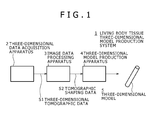
- reference numeral 1 generally denotes a living body tissue three-dimensional model production system, and, in a three-dimensional data acquisition apparatus 2, three-dimensional tomographic data S1 regarding a region including a living body tissue whose living body tissue three-dimensional model is to be produced are acquired from a subject. The acquired data are transferred to an image data processing apparatus 3.
- the three-dimensional data acquisition apparatus 2 is configured from an X-ray CT apparatus, and acquires the three-dimensional tomographic data S1 including 100 to 300 tomographic images, for example, 300 tomographic images, obtained by slicing, with a slice width 1 [mm], a lesion region of an aorta which is a living body tissue, and then supplies the three-dimensional tomographic data S1 to the image data processing apparatus 3.
- the image data processing apparatus 3 extracts image data of a living body tissue region (in the case of the embodiment, a lesion region of an aorta) to be shaped as a living body tissue three-dimensional model from the image data for each slice of the three-dimensional tomographic data S1 and carries out an interpolation editing process for the extracted image data as occasion demands.
- a living body tissue region in the case of the embodiment, a lesion region of an aorta
- the image data processing apparatus 3 produces and supplies tomographic shaping data S2 including planar point data of multi layers to a three-dimensional model production apparatus 4.
- the three-dimensional model production apparatus 4 is configured from an optical shaping apparatus, and irradiates ultraviolet laser light on a liquid surface of liquid-state light-curing resin at a position of the point data for each slice of the tomographic shaping data S2 to harden the resin slices in a predetermined thickness for each slice and laminates the hardened light-curing resin for each slice of the tomographic shaping data S2 to form a three-dimensional model 5 wherein the hardened slices are connected three-dimensionally.
- an optical shaping apparatus of a lamination pitch 0.05 [mm], CMET Inc., RM-3000, can be applied.
- This optical shaping apparatus repetitively carries out lamination operation for selectively irradiating ultraviolet laser light controlled by a computer so that a desired pattern is obtained on a liquid surface of liquid-state light-curing resin placed in a container to harden the fluid light-curing resin in a predetermined thickness and supplying liquid-state resin per one slice onto the hardened slice and then irradiating ultraviolet laser light to harden the liquid-state resin similarly as described above so that a continued hardened slice is obtained.
- urethane acrylate-based light-curing resin composition (refer to
- Patent Document 5 silicon-based light-curing resin composition
- Patent Document 6 silicon-based light-curing resin composition
- the above-described resin composition described above whose ductility is high while whose Young's modulus is low or like resin composition is preferable, and particularly the silicon-based light-curing resin composition is preferable.
- Patent Document 5 Japanese Patent Laid-Open No. Hei 9-169827
- Patent Document 6 Japanese Patent Laid-Open No. 2006-2087
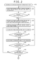
- the image data processing apparatus 3 carries out an image process for the three-dimensional tomographic data S1 supplied from the three-dimensional data acquisition apparatus 2 in accordance with a shaping data production processing procedure RTO illustrated in FIGS. 2 and 3 .
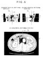
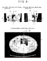
- the three-dimensional tomographic data S1 include, as shown as a representative example by tomographic data at an upper stage portion, a middle stage portion and a lower stage portion in FIGS. 4 , 6 and 8 , horizontal sectional data D11, D12 and D13, front vertical sectional data D21, D22 and D23 and side vertical sectional data D31, D32, and D33, by which a living body tissue of an image point at a three-dimensional position inside the body is represented by the brightness of luminance (accordingly, by the density of an image).
- the horizontal sectional data D11, D12 and D13 shown in (C) of FIG. 4 , (C) of FIG. 6 and (C) of FIG. 8 represent tomographic data at a height of a horizontal sectional line L1 shown in the front vertical sectional data D21, D22 and D23 and the side vertical sectional data D31, D32 and D33 in (A) of FIG. 4 , (A) of FIG. 6 and (A) of FIG. 8 and (B) of FIG. 4 , (B) of FIG. 6 and (B) of FIG. 8 , respectively.
- the front vertical sectional data D21, D22 and D23 and the side vertical sectional data D31, D32 and D33 in (A) of FIG. 4 , (A) of FIG. 6 and (A) of FIG. 8 and (B) of FIG. 4 , (B) of FIG. 6 and (B) of FIG. 8 represent vertical sectional data obtained at a position in a leftward and rightward direction of the human body and a position in a forward and rearward direction of the human body in accordance with a side vertical sectional line L3 and a front vertical sectional line L2 as shown in (C) of FIG. 4 , (C) of FIG. 6 and (C) of FIG. 8 , respectively.
- the user of the image data processing apparatus 3 can select tomographic image data including a region of a living body tissue to be obtained as the tomographic shaping data S2 from within the tomographic data supplied as the three-dimensional tomographic data S1 and causes a display unit of the image data processing apparatus 3 to display the selected data, and can carry out editing operation (image process such as deletion, addition, changing or the like of image data regarding the region of the living body tissue in the image region designated as a target) for the displayed image data.
- editing operation image process such as deletion, addition, changing or the like of image data regarding the region of the living body tissue in the image region designated as a target
- the image data processing apparatus 3 If the image data processing apparatus 3 starts the shaping data production processing procedure RTO, then it selects, first at step SP1, a tomographic image including a living body tissue such as a blood vessel, an organ or the like which is a shaping target (that is, a target) whose living body tissue three-dimensional model is to be formed in response to the designation operation by the user from within the three-dimensional tomographic data S1 and then causes the display unit to display the selected image thereon. Thereafter, at step SP2, the image data processing apparatus 3 asks the user to confirm whether or not the shaping target is correctly identified.
- a tomographic image including a living body tissue such as a blood vessel, an organ or the like which is a shaping target (that is, a target) whose living body tissue three-dimensional model is to be formed in response to the designation operation by the user from within the three-dimensional tomographic data S1 and then causes the display unit to display the selected image thereon.
- the image data processing apparatus 3 asks the user to confirm whether or not the
- the user would move the horizontal sectional line L1, front vertical sectional line L2 and side vertical sectional line L3 to search for a range of the tomographic image including the shaping target (for example, an aorta) inside the human body to recognize a processing target region TG.
- the shaping target for example, an aorta
- the image data processing apparatus 3 advances the processing to step SP3 in response to the designation operation by the user, and extracts those image data having a luminance same as that of the shaping target from the three-dimensional tomographic data in the processing target region TG including the shaping target (that is, the target) and then causes the display unit to display the extracted data thereon.
- the processing target region TG is set in regard to a heightwise range in the upward and downward direction including the target, a widthwise range in the leftward and rightward direction and a depthwise range in the forward and rearward direction, and one slice of the tomographic data which includes the processing target region TG, for example, the upper stage tomographic data shown in FIG. 4 , is displayed on the display unit.
- the aorta designated as the target is a tubeformed living body tissue having a bore in which blood is filled, and, when the three-dimensional tomographic data S1 are acquired for a check of the lesion region by the three-dimensional data acquisition apparatus 2, image pickup is carried out using contrast medium. Therefore, the three-dimensional tomographic data S1 are fetched as such image data that the bore of the blood vessel has light luminance by the image data processing apparatus 3.
- a lumen wall portion of the blood vessel in the processing target region TG is displayed as image data wherein the lumen wall portion and the other tissue on the outer side of the lumen wall portion are not clearly distinguished from each other.
- the image data processing apparatus 3 extracts a boundary between the lumen wall portion of the blood vessel and the tissue on the outer side as the shaping target in accordance with the operation by the user.
- the extraction operation is carried out while the position or the shape of the shaping object (that is, the aorta) inside the body of a healthy person is being assumed or information based on examples of dissection of patients having the same affection is being taken into consideration based on anatomical information.
- horizontal sectional data above and below the horizontal sectional data D11 are referred to so that image data which conform to a flow of a plurality of tomographic images (flow from an upper position to a lower position or flow from a lower position to an upper position) are determined as image data of the shaping object and are cut away from the external tissue.
- an outer shape of the shaping object including the lesion region is different from that of an organ of an anatomically healthy person.
- the outer shape of the lesion region is for example, extraordinary swollen or extraordinary thin. Therefore, extraction of a boundary between the object image and the other organ including the difference is carried out.
- the image data processing apparatus 3 carries out, at next step SP5, a process of erasing the other portion than the shaping object from the processing target region TG.
- the image data processing apparatus 3 can obtain intermediate shaping image data OB1 having an outer shape on one section of the living body tissue three-dimensional model to be shaped from the horizontal sectional data D11 as illustrated in (C) of FIG. 5 and accumulates the intermediate shaping image data OB1 into the internal memory.
- step SP6 the image data processing apparatus 3 returns the processing through step SP6 to step SP3 described hereinabove so that it repetitively carries out processing of the process loop of the steps SP3 - SP4 - SP5 - SP6 - SP3 similarly for the tomographic data of a different one tomogram from among the tomographic data of 300 tomograms.
- the extraction process of the shaping object is successively carried out regarding all tomographic data.
- the image data processing apparatus 3 obtains an affirmative result at step SP6 and advances the processing to step SP7.
- the process at step SP7 is to use the intermediate shaping image data (OB1 to OB3) accumulated in the memory of the image data processing apparatus 3 by the processing at steps SP3 - SP4 - SP5 - SP6 - SP3 to cause the data to be displayed as a three-dimensional image on the display unit.
- the image data processing apparatus 3 causes, at step SP8, the user to make a decision regarding whether or not the shaping object has successfully been extracted correctly. If it is decided that the extraction from the tomographic data is not correct, then the processing returns to step SP3 described hereinabove to carry out the extraction process of the shaping object again.
- the image data processing apparatus 3 causes, at next step SP9, the user to make a decision regarding whether or not the erasure process has successfully been carried out correctly. If a negative result is obtained, then the processing returns to step SP5 described hereinabove, and the image data processing apparatus 3 carries out, at step SP5 described hereinabove, the erasure process of the tomographic data which are estimated not to have correctly undergone the erasure process.
- step SP9 If an affirmative result is obtained at step SP9, then the image data processing apparatus 3 advances the processing to step SP10, at which it removes noise by a smoothing process to smooth the surface. Thereafter, at step SP11, the image data processing apparatus 3 causes the user to make a decision regarding whether or not all data necessary for clinical processing are prepared. If it is confirmed that all data are prepared, then the image data processing apparatus 3 returns the processing to step SP10 described hereinabove to carry out the smoothing process again.
- step SP11 If an affirmative result is obtained at step SP11, then since this signifies that there is no clinical problem, the image data processing apparatus 3 decides at step SP12 whether or not the shaping object is a blood vessel.
- step SP13 the image data processing apparatus 3 advances the processing to step SP13, at which it immediately carries out a production process of tomographic shaping data S2 to be passed to the three-dimensional model production apparatus 4.
- the image data processing apparatus 3 causes, at step SP16, the user to make a decision regarding whether or not a blood vessel wall is extracted.
- step SP13 the image data processing apparatus 3 advances the processing to step SP13, at which it carries out a production process of tomographic shaping data S2 having a bore.
- the shaping object is a blood vessel which does not have a lesion region
- the three-dimensional tomographic data S1 obtained from the three-dimensional data acquisition apparatus 2 are a result of image pickup using a contrast medium
- a lumen wall portion of a blood vessel surrounds the periphery with an anatomically fixed wall thickness, and therefore, an affirmative result is obtained at step SP16.
- step SP16 if a negative result is obtained at step SP16 described hereinabove, then this signifies that the three-dimensional image produced by the processing till then is not completed as a blood vessel as yet.
- the image data processing apparatus 3 returns the processing to step SP17, at which it causes the user to write image data of a lumen wall of a predetermined wall thickness regarding the three-dimensional image produced till then and then displays the three-dimensional image.
- the wall thickness of the blood vessel wall is determined in accordance with conditions of the blood vessel region of the shaping object based on the fact that anatomically a thick blood vessel has a great wall thickness while a thin blood vessel has a small wall thickness.
- step SP18 the image data processing apparatus 3 advances the processing to step SP18, at which it causes the user to make a decision regarding whether or not the blood vessel has some collapse or dissociation.
- the image data processing apparatus 3 corrects the fault at step SP19 and then returns the processing to step SP18 described above. Consequently, the image data processing apparatus 3 repeats the correction process until after the three-dimensional image of the blood vessel becomes free from any fault.
- the image data processing apparatus 3 ends the production process of the tomographic shaping data S2 based on the three-dimensional tomographic data S1 from the three-dimensional data acquisition apparatus 2 at step SP13 and then sends the tomographic shaping data S2 to the three-dimensional model production apparatus 4, which is an optical shaping apparatus, at step SP14 so that a shaping process is carried out. Consequently, the shaping data production processing procedure RTO ends at step SP15.
- the image data processing apparatus 3 extracts, at step SP4 of the shaping data production processing procedure RTO, a boundary between a shaping object and the other tissue. Consequently, as three-dimensional tomographic data 15 of the aorta 11 at the height levels V1, V2, V3 and V4, outer surfaces 11A1, 11A2, 11A3 and 11A4 which are extraordinary swollen at the portion of the aortic aneurysm 12 are extracted.
- the image data processing apparatus 3 causes the user to place wall thicknesses of predetermined lumen walls 11B1, 11B2, 11B3 and 11B4 into the inner side of the outer surfaces 11A1, 11A2, 11A3 and 11A4 of the aorta 11 and then displays a three-dimensional image of the aorta 11 on the display unit.
- the wall thicknesses of the lumen walls 11B1, 11B2, 11B3 and 11B4 are selectively set to comparatively great thicknesses because the aorta 11 is a thick blood vessel.
- blood flow portions 11C1, 11C2, 11C3 and 11C4 of the bore at the lumen walls 11B1, 11B2, 11B3 and 11B4 include a contrast medium therein, they are filled with image data brighter than those of the lumen walls 11B1, 11B2, 11B3 and 11B4.
- the image data processing apparatus 3 when an image process is carried out selecting an aorta as a shaping object, the image data processing apparatus 3 produces a decision result at step SP18 that the blood vessel has dissociation.
- the three-dimensional model 5 obtained from the three-dimensional model production apparatus 4 reconstructs the aorta 11 (which has an internal structure wherein the thrombus 13 exists in the inside of the aortic aneurysm 12) having the aortic aneurysm 12 as shown in FIG. 11 .
- step SP17 when lumen walls 21C1, 21C2, 21C3, 21C4 and 21C5 of the aorta 11 are inputted at step SP17 described hereinabove, if double blood vessel walls 21B2, 21B3, 21B4 and 21B5 exist in the tomographic data at the height levels V12, V13, V14 and V15, then the image data processing apparatus 3 decides at step SP18 that the blood vessel has collapse or dissociation. Therefore, at step SP19, a correction process of the fault is carried out.
- the blood flow portions 21D2, 21D3, 21D4 and 21D5 exist between the double blood vessel walls 21B2, 21B3, 21B4 and 21B5 and the lumen walls 21C2, 21C3, 21C4 and 21C5, and according to circumstances, the double blood vessel walls 21B2, 21B3, 21B4 and 21B5 may partly be cut such that they look in such manner as to hang down like a flap the double blood vessel wall 21B4.
- a three-dimensional model can be produced by reconstructing without being lost blood vessel information which the three-dimensional tomographic data 25 have.
- boundaries 31A2, 31A3 and 31A4 of a small elliptical shape corresponding to a brachiocephalic artery 32, a left common carotid artery 33 and a left subclavian artery 34 are extracted and boundaries 31A5 and 31A6 corresponding to two branches are extracted at the height level V23 on the lower side of the boundary 31A1.
- the shaping data production processing procedure RTO can be simplified by the omission of the processing step.
- an image data process is illustrated where, in the case wherein a region in which an aorta 42 extends from the heart 41 is determined as a shaping object, lumen walls 43A, 43B and 43C are obtained as three-dimensional tomographic data 43 on height levels V31, V32 and V33 of the portion of the aorta 42 and a tomographic image 43D is obtained on a height level V34 of the heart 41 and three-dimensional tomographic data S1 including a shaping object which includes a bypass blood vessel 44 which should not anatomically exist are supplied.
- the image data processing apparatus 3 can extract boundaries 45A, 45B and 45C on the height levels V31, V32 and V33 by extracting the boundary between the shaping object and the other tissue at step SP4 of the shaping data production processing procedure RTO.
- the image data processing apparatus 3 extracts a boundary 45D on the height level V34 between the heart 41 as the shaping object and the other tissue at step SP4 of the shaping data production processing procedure RTO similarly.
- the tomographic data on the height level V32 includes a connecting blood vessel portion 47 in regard to a connecting portion between the aorta 42 and the bypass blood vessel 44.
- Another connecting blood vessel portion 48 is included in a portion at which the bypass blood vessel 44 is connected to the heart 41 on the height level V34.
- the three-dimensional tomographic data 43 include a bypass blood vessel portion 49 in the neighborhood of the lumen wall 43C of the aorta on the height level V33.
- the connecting blood vessel portions 47 and 48 regarding the bypass blood vessel 44 and the bypass blood vessel portion 49 can be decided as blood vessels because, although it cannot be anatomically forecast, that the blood flows 50B and 50C as well as 50D exist in the blood vessel portions is displayed as an image of the contrast medium.
- the image data processing apparatus 3 decides from the specificity of the tomographic data that the bypass blood vessel 44 exists, and carries out an image process of the bypass blood vessel 44.
- the three-dimensional model 5 shown in FIG. 11 is obtained from the tomographic shaping data S2 produced by the image data processing apparatus 3 using the three-dimensional model production apparatus 4 and reconstructs not only the external shape of the same but also the structure of a bore.
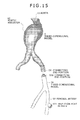
- three-dimensional tomographic data S1 of a femoral artery 5Y positioned far away from the aorta 11 are obtained from the three-dimensional data acquisition apparatus 2 to produce tomographic shaping data S2 using the shaping data production processing procedure RTO illustrated in FIGS. 2 and 3 .
- the tomographic shaping data S2 are processed by the three-dimensional model production apparatus 4 to reconstruct a femoral artery 5Y as a three-dimensional model 5X.
- the three-dimensional model 5X is prepared as a part connecting to a part of the three-dimensional model 5 separately from the three-dimensional model 5 which includes the aortic aneurysm 12.
- the image data processing apparatus 3 carries out processing operation so that an insertion port member 5Y1 which reconstructs an insertion port is provided on the three-dimensional model 5X in a corresponding relationship to the position of a femoral region at which the insertion port is provided in order to clinically insert a catheter into a femoral artery to feed into the aortic aneurysm.
- the insertion port member 5Y1 which is used clinically has a configuration shown in FIG. 16 .
- the insertion port member 5Y1 has an insertion port body 5Y2 having a generally cylindrical shape, and a communicating opening 5Y4 communicating with a bore of the femoral artery is cut away at a side portion of an attaching side end portion 5Y3 to the femoral artery. Consequently, the insertion port member 5Y1 is attached obliquely to the communicating opening 5Y4 such that it extends along the femoral artery.
- a catheter is inserted into an opening of a circular sectional shape of a catheter insertion side end portion 5Y5, and a distal end of the catheter is inserted into the femoral artery through the communicating opening 5Y4.
- the three-dimensional model 5X is produced by adding tomographic data of the insertion port member 5Y1 to tomographic data produced by the image data processing apparatus 3 executing the shaping data production processing procedure RTO of FIGS. 2 and 3 with regard to the three-dimensional tomographic data S1 obtained from the femoral region by the three-dimensional data acquisition apparatus 2.
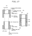
- a fitting portion 5A1 configured as a cylindrical recessed portion is formed, and a circumferential line portion of the connecting end portion 5A is cut in a thick portion of a lumen wall 5A2.
- a projection 5X2 configured as a cylindrical projection is formed on the connecting end portion 5X1 of the three-dimensional model 5X, and a circumferential portion of the projection 5X2 is configured such that an outer circumferential portion of a thick portion of a lumen wall 5X3 is cut away.
- a bore 5A3 of the connecting end portion 5A of the three-dimensional model 5 and a bore 5X4 of a connecting end portion 5X1 of the three-dimensional model 5X have inner diameters equal to each other.
- the projection 5X2 is configured such that it can be fitted in the fitting portion 5A1 without a play, and when a catheter as a surgical instrument inserted in the bore 5X4 of the three-dimensional model 5X passes the boundary of the fitting portion 5A1 from the projection 5X2, since no offset exists at the boundary, the distal end of the catheter can move from the bore 5X4 of the connecting end portion 5X1 to the bore 5A3 of the connecting end portion 5A.
- a three-dimensional model having a bore structure same as a clinical bore structure from the aortic aneurysm 12 to the insertion port member 5Y1 of the femoral artery 5Y positioned in a spaced relationship from the aortic aneurysm 12 is reconstructed by connecting the three-dimensional models 5 and 5X which are different parts from each other.
- the catheter insertion technique from the insertion port member 5Y1 can be attempted prior to carrying out the same in actual clinic.
- a three-dimensional model which reconstructs a living body tissue having a bore such as a blood vessel can be obtained utilizing the fact that the three-dimensional tomographic data S1 obtained from the three-dimensional data acquisition apparatus 2 include image information of a three-dimensional position in the human body.
- a three-dimensional model as a tool with which a state of a tissue in the body including a lesion region or a mark of surgical operation in the past can be forecast sufficiently can be obtained appropriately.
- Such flow indicating elements 51 as shown in FIG. 18 are added to a living body tissue having a tube-like lumen, for example, a blood vessel, in the tomographic shaping data S2 produced by the image data processing apparatus 3 in such a manner as described hereinabove with reference to FIGS. 10 to 14 .
- the flow indicating elements 51 are implanted at suitable intervals for visual observation on a lumen inner face 53 of a lumen wall 52 such that they project into the bore space.
- the flow indicating elements 51 are small pieces each in the form of a thin plate and have a flexible thin leg portion 51A and a flow abutting portion 51B of a greater width formed at an end portion of the leg portion 51A.
- the flow indicating element 51 changes its state in response to a manner in which the fluid flowing in the lumen 54 surrounded by the tube-shaped lumen wall 52 flows, by visually inspecting the variation of the flow indicating elements 51, the flowing manner of the fluid can be discriminated.
- this flow indicating element 51 is applied to a case in which a thrombus exists in an aortic aneurysm described hereinabove, for example, with reference to FIG. 10 , then a flowing manner of the blood in the aortic aneurysm 12 in which the thrombus 13 exists can be confirmed from a flowing manner of the fluid which can be visually inspected from the flow indicating elements 51 of the lumen walls 11B1 and 11B4 in which no thrombus exists and a flowing manner of the fluid which can be discriminated by visually inspecting the flow indicating elements 51 of the lumen walls 11B2 and 11B3 in which the thrombus 13 exists as shown in FIG. 19 .
- the tomographic shaping data S2 including three-dimensional tomographic data where the flow indicating elements 51 are projected on the lumen wall 52 are produced as a three-dimensional model 5 by being supplied from the image data processing apparatus 3 to the three-dimensional model production apparatus 4, when the flow indicating elements 51 are produced from the three-dimensional tomographic data, it is effective to apply an active energy effectiveness resin as disclosed in Patent Document 6.
- the flow indicating elements 51 used are shaped such that a flow abutting portion 51B of a greater width is formed at an end portion of a leg portion 51A
- the shape of the flow indicating element 51 is not limited to this, but flow indicators of various shapes can be applied. What is important is that small pieces in the form of a thin plate project into the lumen 54 of the lumen wall 52 and are yielded by a flow of fluid a.
- the image data processing apparatus 3 can obtain a three-dimensional model 5 by carrying out an image process of the three-dimensional tomographic data S1 acquired from the three-dimensional data acquisition apparatus 2 to produce tomographic shaping data S2 regarding a living body tissue to be targeted and then supplying the tomographic shaping data S2 to the three-dimensional model production apparatus 4.
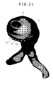
- a motion detection section 62 having a plurality of motion detecting protrusions 61 arrayed thereon is provided on an outer surface of the lumen wall 60 of the three-dimensional model 5.
- a plurality of motion detecting protrusions 61 having a cylindrical shape project from the lumen wall 60 of the aorta 11 and are arrayed such that they have a mutual distance W1 therebetween on an imaginary array line L11 as shown in (A) and (B) of FIG. 22 .
- the mutual distance W1 between the motion detecting protrusions 61 which configure the motion detection section 62 increases to W1X because the outer surface 60A of the lumen wall 60 moves in a direction in which the distance between the motion detecting protrusions 61 increases as the lumen wall 60 is swollen ((C) of FIG. 22 ) from a state before the pressure is applied ((B) of FIG. 22 ).
- the variation of the distance between the motion detecting protrusions 61 corresponds to the degree of swelling of the lumen wall 60 and accordingly to the magnitude of the internal pressure P1.
- the user can find a variation of the swelling manner of the lumen wall 60 and accordingly a variation of the magnitude of the internal pressure P1.
- FIG. 23 shows a motion detection section 66 which can detect distortion applied to the lumen wall 60 as an electric signal by distortion detection elements 65.
- a plurality of distortion detecting holes 60B are perforated on an imaginary array line L12 on the outer surface 60A of the lumen wall 60, and the distortion detection elements 65 are force fitted in the distortion detecting holes 60B as shown (C) of FIG. 23 thereby to configure the motion detection section 66.
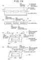
- FIG. 24 shows a motion detection section 69 which detects a variation of the pressure in the lumen wall 60 through a pressure sensing mechanism 70 provided on the lumen wall 60.
- the lumen wall 60 forms unhardened portions 60E in which the light curing resin remains in the form of liquid without being light-cured in a hardened portion 60D in which the light curing resin is light-cured as shown in (B) of FIG. 24 .
- the hardened portion 60D has a configuration wherein a plurality of unhardened portions 60E having a rectangular in horizontal section and having a small thickness in vertical section are arrayed on an imaginary array line L13.
- flexible portions 60C wherein the unhardened portions 60E are sandwiched by thin hardened plate portions 60F and 60G on the upper side and lower side positions are formed.
- the lumen wall 60 has rigidity as an original light curing resin
- the unhardened portions 60E which are intervals of the unhardened liquid-state light curing resin are supported by the thin hardened plate portions 60F and 60G. Therefore, this configuration portion forms a pressure sensing mechanism 70 which reacts with a variation of the pressure in the lumen.
- This pressure sensing mechanism 70 reacts in such a manner that, if the pressure in the lumen surrounded by the lumen wall 60 becomes high, then the hardened plate portions 60F and 60G are displaced so as to move to the outer side together with the unhardened portions 60E.
- a displacement detection section 71 which utilizes such displacement operation of the pressure sensing mechanism 70 as just described so that detection light emitted from a light emitting element 71A is reflected by the surface of the outer side hardened plate portion 60F and received by a light receiving element 71B to detect the displacement operation of the pressure sensing mechanism 70.
- a displacement detection section 72 is provided such that, when the pressure sensing mechanism 70 carries out displacement movement by the pressure in the lumen in a state wherein a contact element 72C provided at an end of a pressure sensing plate 72B projecting from a detector body 72A contacts with the hardened plate portion 60F on the outer side, the pressure sensing plate 72B is pushed up by the displacement movement thereby to output a detection output corresponding to the pushup amount from the detector body 72A.
- the pressure sensing mechanism 70 which carries out displacement operation to the outer side in response to the pressure in the lumen surrounded by the lumen wall 60 is configured by providing the unhardened portions 60E which are liquid-state intervals in which the resin is not light-hardened in the lumen wall 60, the motion detection section 69 by which the shift amount of the pressure sensing mechanism 70, and accordingly a displacement detection output corresponding to the pressure in the lumen, can be obtained can be obtained.
- the lumen wall 60 having high rigidity is configured as the three-dimensional model 5
- a detection output corresponding to the variation of the pressure in the inside of the lumen can be obtained, effective information to investigate the movement of the lumen wall can be obtained with regard to a living body tissue including a lesion region which can be detected by reconstructing the living body tissue.
- the three-dimensional model production apparatus 4 carries out such a process as to form, while liquid-state compartments 81 are left in the inside of an living body tissue region 80 which does not make a bore from within a living body tissue to be targeted, solid-state curing resin 82 in the other region.
- liquid-state compartments 81 in the form of a disk are arrayed on an imaginary array line L14 of the living body tissue region 80 and, in the liquid-state compartments 81, the liquid resin material is left without carrying out a hardening process of the liquid-state active energy curing resin thereby to enclose the liquid-state compartments 81 in the solid-state curing resin 82.
- such a three-dimensional model 5 that a thrombus 13 exists in an aortic aneurysm 12 as a lesion region of an aorta 11 is formed as a three-dimensional model 5 configured such that, as the portions of the lumen wall 83 (11B1 to 11B4 of FIG. 10 ) or the thrombus 13, the liquid-state compartments 81 are enclosed in the solid-state curing resin 82.
- a soft living body tissue is produced by the configuration wherein the liquid-state compartments 81 are enclosed in the solid-state curing resin 82 which forms the lumen wall 83.
- the liquid-state compartments 81 in which the resin remains in the form of liquid without being light-cured are enclosed in the solid-state curing resin 82 in a light-cured state. Therefore, the outer surface of the lumen wall 83 of the three-dimensional model 5 presents a soft touch as the liquid-state compartments 81 are enclosed.
- the three-dimensional model 5 has flexibility proximate to that of a living body tissue inside the body, even if the three-dimensional model 5 is used as an operation technique simulator of compatibility confirmation with a stent graft or a stent and so forth, detailed survey of the three-dimensional model 5 can be carried out without causing the user to feel an uncomfortable feeling.
- the present invention can be utilized where a living body tissue inside the body having a lesion region is reconstructed.
Landscapes
- Engineering & Computer Science (AREA)
- Health & Medical Sciences (AREA)
- Physics & Mathematics (AREA)
- Chemical & Material Sciences (AREA)
- Materials Engineering (AREA)
- Optics & Photonics (AREA)
- Life Sciences & Earth Sciences (AREA)
- Medical Informatics (AREA)
- General Health & Medical Sciences (AREA)
- General Physics & Mathematics (AREA)
- Manufacturing & Machinery (AREA)
- Mechanical Engineering (AREA)
- Theoretical Computer Science (AREA)
- Public Health (AREA)
- Surgery (AREA)
- Molecular Biology (AREA)
- Heart & Thoracic Surgery (AREA)
- Animal Behavior & Ethology (AREA)
- Biomedical Technology (AREA)
- Radiology & Medical Imaging (AREA)
- Pathology (AREA)
- Nuclear Medicine, Radiotherapy & Molecular Imaging (AREA)
- Biophysics (AREA)
- Veterinary Medicine (AREA)
- Mathematical Analysis (AREA)
- Mathematical Physics (AREA)
- Medicinal Chemistry (AREA)
- Algebra (AREA)
- Computational Mathematics (AREA)
- Educational Technology (AREA)
- Educational Administration (AREA)
- Business, Economics & Management (AREA)
- Pure & Applied Mathematics (AREA)
- Mathematical Optimization (AREA)
- High Energy & Nuclear Physics (AREA)
- Vascular Medicine (AREA)
- Dentistry (AREA)
- Oral & Maxillofacial Surgery (AREA)
- Pulmonology (AREA)
- Apparatus For Radiation Diagnosis (AREA)
Abstract
Description
- The present invention relates to a living body tissue three-dimensional model and a production method therefore and is particularly suitable where it is applied to a case wherein a living body tissue having a lesion region inside a human body is reconstructed.
- As a three-dimensional model for reconstructing a living body tissue inside a human body, a three-dimensional model has been proposed wherein tomographic image information is obtained utilizing data of X-ray CT or data of MRI using a contrast medium and then a living body tissue is reconstructed based on three-dimensional data obtained from the tomographic image information (refer to
Patent Documents 1 to 4). -
Patent Document 1 Japanese Patent Laid-Open No.Hei 8-1874 -
Patent Document 2 Japanese Patent Laid-Open No.2006-343434 - Patent Document 3 Japanese Patent Laid-Open No.
Hei 5-11689 -
Patent Document 4 Japanese Patent No.3613568 - When a state of a lesion region appearing in a living body tissue of the living body, particularly, of a lesion region inside the human body, is confirmed and treatment of the lesion region is investigated, it is impossible for a doctor to diagnose the lesion region while directly visually inspecting the lesion region. Therefore, if a living body tissue three-dimensional model of a lesion region inside a human body can be reconstructed and presented, then this has high effectiveness as a tool for carrying out suitable treatment.
- Particularly, regarding a living body tissue having a bore such as a blood vessel, also diagnosis and treatment of a lesion region can be carried out by passing an operation instrument such as a catheter into the bore. Therefore, if a three-dimensional model of a living body tissue in which a lesion region appears can be suitably reconstructed, then it has a high effect in practical use.
- Further, regarding a living body tissue having a tube-like lumen such as a blood vessel, if a flowing manner of fluid such as blood which flows in a lumen can be found utilizing a three-dimensional model, then this is effective to confirm a function of a living body tissue.
- Further, regarding a living body tissue having a tube-like lumen such as a blood vessel, where the pressure of fluid, for example, blood, which passes in a lumen varies, a living body tissue makes such movement as to expand and contract. In addition, if the pressure in a lumen becomes excessively high as a result of insertion of a manipulation instrument into a lumen or expansion or the like of a manipulation instrument in a lumen, then there is the possibility that a lesion region of the living body tissue may make an improper movement such as a rupture.
- In this regard, since a function for finding a movement of a living body tissue reconstructed by a reconstruction structure model is not provided in the past, the existing techniques are still insufficient as a living body tissue model.
- Further, where, for example, a method of hardening light-curing resin using light generated from three-dimensional data is used as a method of reconstructing a living body tissue based on three-dimensional data in the past, since the living body tissue three-dimensional model is reconstructed by hardening active energy-curing resin, it has rigidity higher than that of a living body tissue and therefore lacks in flexibility. Therefore, the living body tissue three-dimensional model does not reconstruct the flexibility of a living body tissue, and enhancement of a function as an operation maneuver simulator such as confirmation of compatibility with a stent or stent graft is demanded.
- The present invention has been made taking the foregoing into consideration and contemplates proposal of a living body tissue three-dimensional model and a production method therefore which make it possible to appropriately reconstruct a lumen portion including a lesion region, make it possible to confirm a flowing manner of fluid, which flows in a lumen in a living body tissue which has the lumen, by visual inspection, or make it possible to grasp, when pressure in a lumen varies, a variation of a region of a living body tissue which occurs in response to the variation of the pressure or else make it possible to produce a living body tissue three-dimensional model so as to have flexibility using hardened resin of active energy-curing resin.
- In order to solve such a subject as described above, according to the present invention, a living body tissue three-dimensional model is configured such that the living body tissue three-dimensional model reconstructs a thickness of a lumen wall portion of a lumen portion including a lesion region of a living body tissue.
- Further, according to the present invention, a living body tissue three-dimensional model is configured such that a living body lumen model produced based on tomographic image data of a living body has a small piece in the form of a thin plate formed in a projecting manner from a lumen wall toward a lumen.
- Or, according to the present invention, a living body tissue three-dimensional model is configured such that pressure in a lumen surrounded by a lumen wall in a living body model produced based on tomographic image data of a living body is measured through displacement which occurs with a measuring structure provided on the lumen wall in response to a variation of the pressure in the lumen.
- Or else, according to the present invention, a living body tissue three-dimensional model is configured such that a living body model produced by hardening liquid-state active energy-curing resin based on tomographic image data of a living body has a liquid-state compartment in which the active energy-curing resin remains unhardened and which is surrounded by the hardened resin.
- With the present invention, since the thickness of the lumen wall portion including the lesion region is reconstructed, the state of the lesion region in the lumen can be visually inspected clearly. As a result, the diagnosis in the lumen can be carried out further easier.
- Further, with the present invention, since the small piece in the form of a thin plate is formed in a projecting manner from the lumen wall toward the lumen, a flowing manner of fluid which flows in the lumen can be confirmed by visually inspecting a movement of the small piece in the form of a thin plate which moves so as to correspond to the flowing manner of the fluid.
- Furthermore, with the present invention, since, when the lumen wall which surrounds the lumen is produced based on tomographic image data of a living body, a measuring structure is formed on the lumen wall such that pressure in the lumen is measured through displacement which occurs with the measuring structure, a motion which occurs with the lumen wall by a variation of the pressure in the lumen can be measured with certainty.
- Furthermore, with the present invention, since, when a living body model of a living body tissue is produced by carrying out a hardening process of active energy-curing resin, the unhardened liquid-state compartment is enclosed in the hardened resin, a living body image main model of a soft touch can be obtained.
-
-
FIG. 1 is a block diagram showing a living body tissue three-dimensional model production system according to an embodiment of the present invention. -
FIG. 2 is a flow chart illustrating a shaping data production processing procedure of an image data processing apparatus 3 inFIG. 1 . -
FIG. 3 is a flow chart illustrating the shaping data production processing procedure of the image data processing apparatus 3 inFIG. 1 . -
FIG. 4 is sectional views showing front vertical sectional data D21, side vertical sectional data D31 and horizontal sectional data D11 regarding upper stage tomographic data. -
FIG. 5 is sectional views showing intermediate shaping image data of the upper stage tomographic data inFIG. 4 . -
FIG. 6 is sectional views showing front vertical sectional data, side vertical sectional data and middle stage tomographic data of middle stage tomographic. -
FIG. 7 is sectional views showing intermediate shaping image data inFIG. 6 . -
FIG. 8 is sectional views showing front vertical sectional data, side vertical section data and horizontal sectional data of lower stage tomographic data. -
FIG. 9 is sectional views showing intermediate shaping image data inFIG. 8 . -
FIG. 10 is a schematic view illustrating a process where a thrombus exists in an aortic aneurysm. -
FIG. 11 is a side elevational view showing a produced three-dimensional model. -
FIG. 12 is a schematic view illustrating a process of image data where aorta dissociation is found. -
FIG. 13 is a schematic view illustrating a process of image data where bifurcation of a blood vessel is found. -
FIG. 14 is a schematic view illustrating an image process where a blood vessel which should not originally exist is found. -
FIG. 15 is a side elevational view illustrating a three-dimensional model which is configured so that an operation instrument can be inserted. -
FIG. 16 is a side elevational view showing an insertion port inFIG. 15 . -
FIG. 17 is sectional views showing a configuration of a connection end portion inFIG. 15 . -
FIG. 18 is a partial sectional view showing a three-dimensional model wherein a flow indicating element projects from a lumen wall. -
FIG. 19 is a schematic view illustrating a case wherein a flow indicating element is applied where a thrombus exists in an aortic aneurysm. -
FIG. 20 is a perspective view showing a motion detection section provided on a three-dimensional model. -
FIG. 21 is a perspective view showing the motion detection section as viewed from a different direction from that inFIG. 20 . -
FIG. 22 is schematic views illustrating motion detection operation by a motion detecting protrusion. -
FIG. 23 is schematic views illustrating motion detection operation by a distortion detection element. -
FIG. 24 is schematic views illustrating motion detection operation by a pressure sensing mechanism. -
FIG. 25 is schematic views illustrating a formation process of a liquid-state compartment. -
FIG. 26 is a side elevational view showing an embodiment applied to a three-dimensional model of an aorta wherein a thrombus exists in an aortic aneurysm. -
FIG. 27 is a sectional view showing a horizontal sectional structure inFIG. 26 . - In the following, an embodiment of the present invention is described in detail with reference to the drawings.
- Referring to
FIG. 1 ,reference numeral 1 generally denotes a living body tissue three-dimensional model production system, and, in a three-dimensionaldata acquisition apparatus 2, three-dimensional tomographic data S1 regarding a region including a living body tissue whose living body tissue three-dimensional model is to be produced are acquired from a subject. The acquired data are transferred to an image data processing apparatus 3. - In the case of the present embodiment, the three-dimensional
data acquisition apparatus 2 is configured from an X-ray CT apparatus, and acquires the three-dimensional tomographic data S1 including 100 to 300 tomographic images, for example, 300 tomographic images, obtained by slicing, with a slice width 1 [mm], a lesion region of an aorta which is a living body tissue, and then supplies the three-dimensional tomographic data S1 to the image data processing apparatus 3. - The image data processing apparatus 3 extracts image data of a living body tissue region (in the case of the embodiment, a lesion region of an aorta) to be shaped as a living body tissue three-dimensional model from the image data for each slice of the three-dimensional tomographic data S1 and carries out an interpolation editing process for the extracted image data as occasion demands.
- Thus, the image data processing apparatus 3 produces and supplies tomographic shaping data S2 including planar point data of multi layers to a three-dimensional
model production apparatus 4. - The three-dimensional
model production apparatus 4 is configured from an optical shaping apparatus, and irradiates ultraviolet laser light on a liquid surface of liquid-state light-curing resin at a position of the point data for each slice of the tomographic shaping data S2 to harden the resin slices in a predetermined thickness for each slice and laminates the hardened light-curing resin for each slice of the tomographic shaping data S2 to form a three-dimensional model 5 wherein the hardened slices are connected three-dimensionally. - Here, as the three-dimensional
model production apparatus 4, for example, an optical shaping apparatus of a lamination pitch 0.05 [mm], CMET Inc., RM-3000, can be applied. - This optical shaping apparatus repetitively carries out lamination operation for selectively irradiating ultraviolet laser light controlled by a computer so that a desired pattern is obtained on a liquid surface of liquid-state light-curing resin placed in a container to harden the fluid light-curing resin in a predetermined thickness and supplying liquid-state resin per one slice onto the hardened slice and then irradiating ultraviolet laser light to harden the liquid-state resin similarly as described above so that a continued hardened slice is obtained.
- Further, as the light-curing resin, urethane acrylate-based light-curing resin composition (refer to
- Patent Document 5) and silicon-based light-curing resin composition (refer to Patent Document 6) can be applied.
- Where a model of a living body tissue other than a bone and a tooth is to be produced, the above-described resin composition described above whose ductility is high while whose Young's modulus is low or like resin composition is preferable, and particularly the silicon-based light-curing resin composition is preferable.
-
Patent Document 5 Japanese Patent Laid-Open No.Hei 9-169827 - Patent Document 6 Japanese Patent Laid-Open No.
2006-2087 - The image data processing apparatus 3 carries out an image process for the three-dimensional tomographic data S1 supplied from the three-dimensional
data acquisition apparatus 2 in accordance with a shaping data production processing procedure RTO illustrated inFIGS. 2 and3 . - In the case of the present embodiment, the three-dimensional tomographic data S1 include, as shown as a representative example by tomographic data at an upper stage portion, a middle stage portion and a lower stage portion in
FIGS. 4 ,6 and8 , horizontal sectional data D11, D12 and D13, front vertical sectional data D21, D22 and D23 and side vertical sectional data D31, D32, and D33, by which a living body tissue of an image point at a three-dimensional position inside the body is represented by the brightness of luminance (accordingly, by the density of an image). - Here, the horizontal sectional data D11, D12 and D13 shown in
(C) of FIG. 4 ,(C) of FIG. 6 and(C) of FIG. 8 represent tomographic data at a height of a horizontal sectional line L1 shown in the front vertical sectional data D21, D22 and D23 and the side vertical sectional data D31, D32 and D33 in(A) of FIG. 4 ,(A) of FIG. 6 and(A) of FIG. 8 and(B) of FIG. 4 ,(B) of FIG. 6 and(B) of FIG. 8 , respectively. - Similarly, the front vertical sectional data D21, D22 and D23 and the side vertical sectional data D31, D32 and D33 in
(A) of FIG. 4 ,(A) of FIG. 6 and(A) of FIG. 8 and(B) of FIG. 4 ,(B) of FIG. 6 and(B) of FIG. 8 represent vertical sectional data obtained at a position in a leftward and rightward direction of the human body and a position in a forward and rearward direction of the human body in accordance with a side vertical sectional line L3 and a front vertical sectional line L2 as shown in(C) of FIG. 4 ,(C) of FIG. 6 and(C) of FIG. 8 , respectively. - Thus, by operating to designate a position of the horizontal sectional line L1, front vertical sectional line L2 and side vertical sectional line L3, the user of the image data processing apparatus 3 can select tomographic image data including a region of a living body tissue to be obtained as the tomographic shaping data S2 from within the tomographic data supplied as the three-dimensional tomographic data S1 and causes a display unit of the image data processing apparatus 3 to display the selected data, and can carry out editing operation (image process such as deletion, addition, changing or the like of image data regarding the region of the living body tissue in the image region designated as a target) for the displayed image data.
- If the image data processing apparatus 3 starts the shaping data production processing procedure RTO, then it selects, first at step SP1, a tomographic image including a living body tissue such as a blood vessel, an organ or the like which is a shaping target (that is, a target) whose living body tissue three-dimensional model is to be formed in response to the designation operation by the user from within the three-dimensional tomographic data S1 and then causes the display unit to display the selected image thereon. Thereafter, at step SP2, the image data processing apparatus 3 asks the user to confirm whether or not the shaping target is correctly identified.
- In the case of the present embodiment, the user would move the horizontal sectional line L1, front vertical sectional line L2 and side vertical sectional line L3 to search for a range of the tomographic image including the shaping target (for example, an aorta) inside the human body to recognize a processing target region TG.
- At this time, the image data processing apparatus 3 advances the processing to step SP3 in response to the designation operation by the user, and extracts those image data having a luminance same as that of the shaping target from the three-dimensional tomographic data in the processing target region TG including the shaping target (that is, the target) and then causes the display unit to display the extracted data thereon.
- In the case of the present embodiment, taking a lesion region of an aorta as the target, the processing target region TG is set in regard to a heightwise range in the upward and downward direction including the target, a widthwise range in the leftward and rightward direction and a depthwise range in the forward and rearward direction, and one slice of the tomographic data which includes the processing target region TG, for example, the upper stage tomographic data shown in
FIG. 4 , is displayed on the display unit. - Here, the aorta designated as the target is a tubeformed living body tissue having a bore in which blood is filled, and, when the three-dimensional tomographic data S1 are acquired for a check of the lesion region by the three-dimensional
data acquisition apparatus 2, image pickup is carried out using contrast medium. Therefore, the three-dimensional tomographic data S1 are fetched as such image data that the bore of the blood vessel has light luminance by the image data processing apparatus 3. - On the other hand, in the horizontal sectional data D11 illustrated in (C) of
FIG. 4 , a lumen wall portion of the blood vessel in the processing target region TG is displayed as image data wherein the lumen wall portion and the other tissue on the outer side of the lumen wall portion are not clearly distinguished from each other. - Therefore, at next step SP4, the image data processing apparatus 3 extracts a boundary between the lumen wall portion of the blood vessel and the tissue on the outer side as the shaping target in accordance with the operation by the user.
- The extraction operation is carried out while the position or the shape of the shaping object (that is, the aorta) inside the body of a healthy person is being assumed or information based on examples of dissection of patients having the same affection is being taken into consideration based on anatomical information.
- In fact, when some difference exists in density between a blood vessel which is an object of extraction and the other organ, it is decided that an image data portion of a density same as that of a lumen wall portion of a blood vessel is a blood vessel and is cut away from an image of the external tissue to carry out an extraction operation of the blood vessel along an outer wall of the shaping object.
- Further, where it is impossible to cut away the blood vessel from the external tissue only with the horizontal sectional data D11 of (C) of
FIG. 4 , horizontal sectional data above and below the horizontal sectional data D11 are referred to so that image data which conform to a flow of a plurality of tomographic images (flow from an upper position to a lower position or flow from a lower position to an upper position) are determined as image data of the shaping object and are cut away from the external tissue. - Further, once in a while, where the shaping object includes a lesion region, although there is no difference in density, an outer shape of the shaping object including the lesion region is different from that of an organ of an anatomically healthy person. The outer shape of the lesion region is for example, extraordinary swollen or extraordinary thin. Therefore, extraction of a boundary between the object image and the other organ including the difference is carried out.
- Thus, if the extraction process of a boundary between the shaping object and the other tissue ends, then the image data processing apparatus 3 carries out, at next step SP5, a process of erasing the other portion than the shaping object from the processing target region TG.
- As a result, the image data processing apparatus 3 can obtain intermediate shaping image data OB1 having an outer shape on one section of the living body tissue three-dimensional model to be shaped from the horizontal sectional data D11 as illustrated in (C) of
FIG. 5 and accumulates the intermediate shaping image data OB1 into the internal memory. - If the extraction process of a shaping object from such tomographic data of one tomogram ends, then the image data processing apparatus 3 returns the processing through step SP6 to step SP3 described hereinabove so that it repetitively carries out processing of the process loop of the steps SP3 - SP4 - SP5 - SP6 - SP3 similarly for the tomographic data of a different one tomogram from among the tomographic data of 300 tomograms. By this, the extraction process of the shaping object is successively carried out regarding all tomographic data.
- Thus, by carrying out the extraction process, for example, regarding the horizontal sectional data D12 of the middle stage tomographic data illustrated in (C) of
FIG. 6 , such horizontal sectional data D12 from which intermediate shaping image data OB2 are extracted as illustrated in (C) ofFIG. 7 can be obtained. - Further, by carrying out the extraction process of the horizontal sectional data D13 of the lower stage tomographic data illustrated in (C) of
FIG. 8 in a similar manner, such horizontal sectional data D13 from which intermediate shaping image data OB3 are extracted as illustrated in (C) ofFIG. 9 can be obtained. - Thus, if the process of the tomographic data of all of the 300 tomograms ends in this manner, then the image data processing apparatus 3 obtains an affirmative result at step SP6 and advances the processing to step SP7.
- The process at step SP7 is to use the intermediate shaping image data (OB1 to OB3) accumulated in the memory of the image data processing apparatus 3 by the processing at steps SP3 - SP4 - SP5 - SP6 - SP3 to cause the data to be displayed as a three-dimensional image on the display unit.
- Subsequently to the displaying process of the three-dimensional image, the image data processing apparatus 3 causes, at step SP8, the user to make a decision regarding whether or not the shaping object has successfully been extracted correctly. If it is decided that the extraction from the tomographic data is not correct, then the processing returns to step SP3 described hereinabove to carry out the extraction process of the shaping object again.
- On the other hand, if it is decided that the shaping object has successfully been extracted correctly, then the image data processing apparatus 3 causes, at next step SP9, the user to make a decision regarding whether or not the erasure process has successfully been carried out correctly. If a negative result is obtained, then the processing returns to step SP5 described hereinabove, and the image data processing apparatus 3 carries out, at step SP5 described hereinabove, the erasure process of the tomographic data which are estimated not to have correctly undergone the erasure process.
- If an affirmative result is obtained at step SP9, then the image data processing apparatus 3 advances the processing to step SP10, at which it removes noise by a smoothing process to smooth the surface. Thereafter, at step SP11, the image data processing apparatus 3 causes the user to make a decision regarding whether or not all data necessary for clinical processing are prepared. If it is confirmed that all data are prepared, then the image data processing apparatus 3 returns the processing to step SP10 described hereinabove to carry out the smoothing process again.
- If an affirmative result is obtained at step SP11, then since this signifies that there is no clinical problem, the image data processing apparatus 3 decides at step SP12 whether or not the shaping object is a blood vessel.
- Here, if a negative result is obtained, then the image data processing apparatus 3 advances the processing to step SP13, at which it immediately carries out a production process of tomographic shaping data S2 to be passed to the three-dimensional
model production apparatus 4. - On the other hand, if an affirmative result is obtained at step SP12, then since this signifies that the three-dimensional images which have been processed till then require a bore, the image data processing apparatus 3 causes, at step SP16, the user to make a decision regarding whether or not a blood vessel wall is extracted.
- If an affirmative result is obtained here, then this signifies that a blood vessel is shaped already as the shaping object. At this time, the image data processing apparatus 3 advances the processing to step SP13, at which it carries out a production process of tomographic shaping data S2 having a bore.
- Incidentally, if the shaping object is a blood vessel which does not have a lesion region, then since the three-dimensional tomographic data S1 obtained from the three-dimensional
data acquisition apparatus 2 are a result of image pickup using a contrast medium, a lumen wall portion of a blood vessel surrounds the periphery with an anatomically fixed wall thickness, and therefore, an affirmative result is obtained at step SP16. - On the other hand, if a negative result is obtained at step SP16 described hereinabove, then this signifies that the three-dimensional image produced by the processing till then is not completed as a blood vessel as yet.
- Therefore, the image data processing apparatus 3 returns the processing to step SP17, at which it causes the user to write image data of a lumen wall of a predetermined wall thickness regarding the three-dimensional image produced till then and then displays the three-dimensional image.
- Here, the wall thickness of the blood vessel wall is determined in accordance with conditions of the blood vessel region of the shaping object based on the fact that anatomically a thick blood vessel has a great wall thickness while a thin blood vessel has a small wall thickness.
- Then, the image data processing apparatus 3 advances the processing to step SP18, at which it causes the user to make a decision regarding whether or not the blood vessel has some collapse or dissociation.
- If a negative result is obtained here, then the image data processing apparatus 3 corrects the fault at step SP19 and then returns the processing to step SP18 described above. Consequently, the image data processing apparatus 3 repeats the correction process until after the three-dimensional image of the blood vessel becomes free from any fault.
- Thus, the image data processing apparatus 3 ends the production process of the tomographic shaping data S2 based on the three-dimensional tomographic data S1 from the three-dimensional
data acquisition apparatus 2 at step SP13 and then sends the tomographic shaping data S2 to the three-dimensionalmodel production apparatus 4, which is an optical shaping apparatus, at step SP14 so that a shaping process is carried out. Consequently, the shaping data production processing procedure RTO ends at step SP15. - The following cases are available as the correction process of a fault at steps SP18 - SP19 - SP18 of the shaping data production processing procedure RTO described above.
- When three-dimensional tomographic data S1 which include a
thrombus 13 because anaortic aneurysm 12 appears on anaorta 11 as shown inFIG. 10 is supplied, the image data processing apparatus 3 extracts, at step SP4 of the shaping data production processing procedure RTO, a boundary between a shaping object and the other tissue. Consequently, as three-dimensional tomographic data 15 of theaorta 11 at the height levels V1, V2, V3 and V4, outer surfaces 11A1, 11A2, 11A3 and 11A4 which are extraordinary swollen at the portion of theaortic aneurysm 12 are extracted. - Then at step SP17 described above, the image data processing apparatus 3 causes the user to place wall thicknesses of predetermined lumen walls 11B1, 11B2, 11B3 and 11B4 into the inner side of the outer surfaces 11A1, 11A2, 11A3 and 11A4 of the
aorta 11 and then displays a three-dimensional image of theaorta 11 on the display unit. - Here, the wall thicknesses of the lumen walls 11B1, 11B2, 11B3 and 11B4 are selectively set to comparatively great thicknesses because the
aorta 11 is a thick blood vessel. - Further, since blood flow portions 11C1, 11C2, 11C3 and 11C4 of the bore at the lumen walls 11B1, 11B2, 11B3 and 11B4 include a contrast medium therein, they are filled with image data brighter than those of the lumen walls 11B1, 11B2, 11B3 and 11B4.
- Therefore, such image data are obtained which represent that, while the blood flow portions 11C1 and 11C4 at the height levels V1 and V4 at which the
thrombus 13 does not exist contact as a whole with the inner face of the lumen walls 11B1 and 11B4, the blood flow portions 11C2 and 11C3 at which thethrombus 13 exists do not contact with the lumen walls 11B2 and 11B3 at thrombus portions 11D2 and 11D3 and an image portion having a density substantially proximate to the density of theaorta 11 is interposed between them. - Thus, when an image process is carried out selecting an aorta as a shaping object, the image data processing apparatus 3 produces a decision result at step SP18 that the blood vessel has dissociation.
- Therefore, if, at the fault correction step SP19, the tomographic shaping data S2 corrected such that the thrombus portions 11D2 and 11D3 make an image cut away from that of the lumen walls 11B2 and 11B3 of the
aorta 11 are produced, then the three-dimensional model 5 obtained from the three-dimensionalmodel production apparatus 4 reconstructs the aorta 11 (which has an internal structure wherein thethrombus 13 exists in the inside of the aortic aneurysm 12) having theaortic aneurysm 12 as shown inFIG. 11 . - In the case in which an
aorta 21 which is normal at a height level V11 according to anatomical information has a swelling 22 at height levels V12 to V15, if a boundary is extracted between a shaping object and the other tissue at step SP4 of the shaping data production processing procedure RTO from three-dimensional tomographic data 25 obtained based on the three-dimensional tomographic data S1 obtained from the three-dimensionaldata acquisition apparatus 2, then boundaries 21A1, 21A2, 21A3, 21A4 and 21A5 are obtained. - Then, when lumen walls 21C1, 21C2, 21C3, 21C4 and 21C5 of the
aorta 11 are inputted at step SP17 described hereinabove, if double blood vessel walls 21B2, 21B3, 21B4 and 21B5 exist in the tomographic data at the height levels V12, V13, V14 and V15, then the image data processing apparatus 3 decides at step SP18 that the blood vessel has collapse or dissociation. Therefore, at step SP19, a correction process of the fault is carried out. - In the case of the present embodiment, it can be confirmed that the blood flow portions 21D2, 21D3, 21D4 and 21D5 exist between the double blood vessel walls 21B2, 21B3, 21B4 and 21B5 and the lumen walls 21C2, 21C3, 21C4 and 21C5, and according to circumstances, the double blood vessel walls 21B2, 21B3, 21B4 and 21B5 may partly be cut such that they look in such manner as to hang down like a flap the double blood vessel wall 21B4.
- If such a blood vessel as just described can be confirmed at step SP18, then a three-dimensional model can be produced by reconstructing without being lost blood vessel information which the three-
dimensional tomographic data 25 have. - As shown in
FIG. 13 , if three-dimensional tomographic data S1 regarding anaortic arch 31 of the pectoral region are taken in from the three-dimensionaldata acquisition apparatus 2, then when the image data processing apparatus 3 extracts a boundary between a shaping object and the other tissue at step SP4 of the shaping data production processing procedure RTO, a boundary 31A1 of a large elliptical shape is extracted at the height level V22. However, at the height level V21 higher than the body portion, boundaries 31A2, 31A3 and 31A4 of a small elliptical shape corresponding to abrachiocephalic artery 32, a left commoncarotid artery 33 and a leftsubclavian artery 34 are extracted and boundaries 31A5 and 31A6 corresponding to two branches are extracted at the height level V23 on the lower side of the boundary 31A1. - When such three-
dimensional tomographic data 35 of a shaping object image are obtained, since bright image data exist in the inside of the boundaries 31A1 to 31A6 due to a contrast medium included in the blood flows 31B1 to 31B6, the lumen walls 31C1 to 31C6 are extracted. Thus, if it is confirmed at step SP6 described hereinabove that there is no anatomical contradiction, then an affirmative result is obtained at step SP16 for deciding whether or not a blood vessel wall is extracted. Therefore, inputting of a wall thickness at step SP17 is omitted, and the processing advances to the shaping data production processing step SP13. - By the configuration described above, the shaping data production processing procedure RTO can be simplified by the omission of the processing step.
- Referring to
FIG. 14 , an image data process is illustrated where, in the case wherein a region in which anaorta 42 extends from theheart 41 is determined as a shaping object,lumen walls dimensional tomographic data 43 on height levels V31, V32 and V33 of the portion of theaorta 42 and atomographic image 43D is obtained on a height level V34 of theheart 41 and three-dimensional tomographic data S1 including a shaping object which includes abypass blood vessel 44 which should not anatomically exist are supplied. - In this instance, the image data processing apparatus 3 can extract
boundaries - Together with this, the image data processing apparatus 3 extracts a
boundary 45D on the height level V34 between theheart 41 as the shaping object and the other tissue at step SP4 of the shaping data production processing procedure RTO similarly. - Here, while, on the height levels V31, V32 and V33, picked up images of the blood flows 46A, 46B and 46C are obtained on the inner side of the
lumen walls - While the process of image data described above is carried out in accordance with anatomic information, in the case of the shaping object of
FIG. 14 , processing of image data regarding thebypass blood vessel 44 is carried out in addition. - In other words, the tomographic data on the height level V32 includes a connecting
blood vessel portion 47 in regard to a connecting portion between theaorta 42 and thebypass blood vessel 44. - Another connecting
blood vessel portion 48 is included in a portion at which thebypass blood vessel 44 is connected to theheart 41 on the height level V34. - Furthermore, the three-
dimensional tomographic data 43 include a bypassblood vessel portion 49 in the neighborhood of thelumen wall 43C of the aorta on the height level V33. - The connecting
blood vessel portions bypass blood vessel 44 and the bypassblood vessel portion 49 can be decided as blood vessels because, although it cannot be anatomically forecast, that the blood flows 50B and 50C as well as 50D exist in the blood vessel portions is displayed as an image of the contrast medium. - Thus, since, as regards the
bypass blood vessel 44, tomographic data of the same in the heightwise direction from the connectingblood vessel portion 47 to the connectingblood vessel portion 48 through the bypassblood vessel portion 49 are produced continuously, the image data processing apparatus 3 decides from the specificity of the tomographic data that thebypass blood vessel 44 exists, and carries out an image process of thebypass blood vessel 44. - The three-
dimensional model 5 shown inFIG. 11 is obtained from the tomographic shaping data S2 produced by the image data processing apparatus 3 using the three-dimensionalmodel production apparatus 4 and reconstructs not only the external shape of the same but also the structure of a bore. - Therefore, it is high in effectiveness if it is possible to attempt such a clinical technique as to insert a surgical instrument for operating a thrombus 13 (
FIG. 10 ) existing in a bore of theaortic aneurysm 12 utilizing the three-dimensional model to a position of theaortic aneurysm 12. - As a tool investigated before such a surgical technique is carried out clinically, as shown in
FIG. 15 , three-dimensional tomographic data S1 of afemoral artery 5Y positioned far away from theaorta 11 are obtained from the three-dimensionaldata acquisition apparatus 2 to produce tomographic shaping data S2 using the shaping data production processing procedure RTO illustrated inFIGS. 2 and3 . Then, the tomographic shaping data S2 are processed by the three-dimensionalmodel production apparatus 4 to reconstruct afemoral artery 5Y as a three-dimensional model 5X. - Here, since the
femoral artery 5Y is positioned surgically in a spaced relationship from theaortic aneurysm 12 of the three-dimensional model 5, the three-dimensional model 5X is prepared as a part connecting to a part of the three-dimensional model 5 separately from the three-dimensional model 5 which includes theaortic aneurysm 12. - Thereupon, the image data processing apparatus 3 carries out processing operation so that an insertion port member 5Y1 which reconstructs an insertion port is provided on the three-
dimensional model 5X in a corresponding relationship to the position of a femoral region at which the insertion port is provided in order to clinically insert a catheter into a femoral artery to feed into the aortic aneurysm. - The insertion port member 5Y1 which is used clinically has a configuration shown in
FIG. 16 . - The insertion port member 5Y1 has an insertion port body 5Y2 having a generally cylindrical shape, and a communicating opening 5Y4 communicating with a bore of the femoral artery is cut away at a side portion of an attaching side end portion 5Y3 to the femoral artery. Consequently, the insertion port member 5Y1 is attached obliquely to the communicating opening 5Y4 such that it extends along the femoral artery.
- Thus, a catheter is inserted into an opening of a circular sectional shape of a catheter insertion side end portion 5Y5, and a distal end of the catheter is inserted into the femoral artery through the communicating opening 5Y4.
- Here, since the technique of inserting a catheter after the insertion port member 5Y1 is attached is carried out as a series of operations, it is made possible to attempt an insertion operation of a catheter prior to the surgical operation using the three-
dimensional models - The three-
dimensional model 5X is produced by adding tomographic data of the insertion port member 5Y1 to tomographic data produced by the image data processing apparatus 3 executing the shaping data production processing procedure RTO ofFIGS. 2 and3 with regard to the three-dimensional tomographic data S1 obtained from the femoral region by the three-dimensionaldata acquisition apparatus 2. - At a connecting
end portion 5A of the three-dimensional model 5 to the three-dimensional model 5X which are formed as different parts from each other, a fitting portion 5A1 configured as a cylindrical recessed portion is formed, and a circumferential line portion of the connectingend portion 5A is cut in a thick portion of a lumen wall 5A2. - In contrast, a projection 5X2 configured as a cylindrical projection is formed on the connecting end portion 5X1 of the three-
dimensional model 5X, and a circumferential portion of the projection 5X2 is configured such that an outer circumferential portion of a thick portion of a lumen wall 5X3 is cut away. - A bore 5A3 of the connecting
end portion 5A of the three-dimensional model 5 and a bore 5X4 of a connecting end portion 5X1 of the three-dimensional model 5X have inner diameters equal to each other. - As shown in (B) of
FIG. 17 , the projection 5X2 is configured such that it can be fitted in the fitting portion 5A1 without a play, and when a catheter as a surgical instrument inserted in the bore 5X4 of the three-dimensional model 5X passes the boundary of the fitting portion 5A1 from the projection 5X2, since no offset exists at the boundary, the distal end of the catheter can move from the bore 5X4 of the connecting end portion 5X1 to the bore 5A3 of the connectingend portion 5A. - Thus, a three-dimensional model having a bore structure same as a clinical bore structure from the
aortic aneurysm 12 to the insertion port member 5Y1 of thefemoral artery 5Y positioned in a spaced relationship from theaortic aneurysm 12 is reconstructed by connecting the three-dimensional models - As a result, if the installation position or the installation angle of the insertion port member 5Y1 is inappropriate from the appearance position of an aortic aneurysm in the bore of the
aorta 11, this can be confirmed in advance. - Thereupon, if a plurality of three-
dimensional models 5X which are different in the installation position and the installation angle in accordance with different conditions are prepared in advance and one of them is connected to the connectingend portion 5A of the three-dimensional model 5 having theaortic aneurysm 12 through the connecting end portion 5X1, then further optimum installation conditions of the insertion port member 5Y1 can be confirmed. - With the configuration described above, a three-dimensional model which reconstructs a living body tissue having a bore such as a blood vessel can be obtained utilizing the fact that the three-dimensional tomographic data S1 obtained from the three-dimensional
data acquisition apparatus 2 include image information of a three-dimensional position in the human body. - Thus, a three-dimensional model as a tool with which a state of a tissue in the body including a lesion region or a mark of surgical operation in the past can be forecast sufficiently can be obtained appropriately.
- Together with this, by providing an insertion port member with which a surgical instrument can be inserted into a blood vessel on a three-dimensional model, a clinical technique can be attempted in advance, and consequently, a surgical operation can be carried out more readily.
- Such
flow indicating elements 51 as shown inFIG. 18 are added to a living body tissue having a tube-like lumen, for example, a blood vessel, in the tomographic shaping data S2 produced by the image data processing apparatus 3 in such a manner as described hereinabove with reference toFIGS. 10 to 14 . - The
flow indicating elements 51 are implanted at suitable intervals for visual observation on a lumeninner face 53 of alumen wall 52 such that they project into the bore space. - In the case of the present embodiment, the
flow indicating elements 51 are small pieces each in the form of a thin plate and have a flexiblethin leg portion 51A and aflow abutting portion 51B of a greater width formed at an end portion of theleg portion 51A. - Thus, when fluid (pseudo fluid corresponding to the blood) indicated by an arrow mark a flows in a
lumen 54 surrounded by thelumen wall 52 and is brought into abutment with theflow abutting portion 51B of aflow indicating element 51 projecting from the lumeninner face 53, since theflow abutting portion 51B is formed with a greater width, it is acted upon by force from the fluid such that it is inclined or is turned so as to change the direction. - Thus, since the
flow indicating element 51 changes its state in response to a manner in which the fluid flowing in thelumen 54 surrounded by the tube-shapedlumen wall 52 flows, by visually inspecting the variation of theflow indicating elements 51, the flowing manner of the fluid can be discriminated. - If this
flow indicating element 51 is applied to a case in which a thrombus exists in an aortic aneurysm described hereinabove, for example, with reference toFIG. 10 , then a flowing manner of the blood in theaortic aneurysm 12 in which thethrombus 13 exists can be confirmed from a flowing manner of the fluid which can be visually inspected from theflow indicating elements 51 of the lumen walls 11B1 and 11B4 in which no thrombus exists and a flowing manner of the fluid which can be discriminated by visually inspecting theflow indicating elements 51 of the lumen walls 11B2 and 11B3 in which thethrombus 13 exists as shown inFIG. 19 . - With the configuration described above, since an influence of the fluid flowing in a lumen surrounded by a lumen wall can be visually inspected from the
flow indicating elements 51 projecting from the lumeninner face 53 of thelumen wall 52, information for diagnosis of a relationship between a flowing manner of fluid and a lesion region can be provided. - In fact, although the tomographic shaping data S2 including three-dimensional tomographic data where the
flow indicating elements 51 are projected on thelumen wall 52 are produced as a three-dimensional model 5 by being supplied from the image data processing apparatus 3 to the three-dimensionalmodel production apparatus 4, when theflow indicating elements 51 are produced from the three-dimensional tomographic data, it is effective to apply an active energy effectiveness resin as disclosed in Patent Document 6. - It is to be noted that, while, in the embodiment of
FIG. 18 , theflow indicating elements 51 used are shaped such that aflow abutting portion 51B of a greater width is formed at an end portion of aleg portion 51A, the shape of theflow indicating element 51 is not limited to this, but flow indicators of various shapes can be applied. What is important is that small pieces in the form of a thin plate project into thelumen 54 of thelumen wall 52 and are yielded by a flow of fluid a. - As described above, the image data processing apparatus 3 can obtain a three-
dimensional model 5 by carrying out an image process of the three-dimensional tomographic data S1 acquired from the three-dimensionaldata acquisition apparatus 2 to produce tomographic shaping data S2 regarding a living body tissue to be targeted and then supplying the tomographic shaping data S2 to the three-dimensionalmodel production apparatus 4. - If such a three-
dimensional model 5 as shown inFIGS. 20 and21 is reconstructed as a three-dimensional model which reconstructs theaorta 11 including a lesion region of theaortic aneurysm 12 in which athrombus 13 exists as described hereinabove with reference toFIGS. 10 and11 , amotion detection section 62 having a plurality ofmotion detecting protrusions 61 arrayed thereon is provided on an outer surface of thelumen wall 60 of the three-dimensional model 5. - In the case of the present embodiment, on the
motion detection section 62, a plurality ofmotion detecting protrusions 61 having a cylindrical shape project from thelumen wall 60 of theaorta 11 and are arrayed such that they have a mutual distance W1 therebetween on an imaginary array line L11 as shown in (A) and (B) ofFIG. 22 . - In the configuration described above, if pressure is applied to the lumen surrounded by the
lumen wall 60, then thelumen wall 60 is acted upon by internal pressure P1 and swollen to the outer side as shown in (C) ofFIG. 22 . - At this time, the mutual distance W1 between the
motion detecting protrusions 61 which configure themotion detection section 62 increases to W1X because theouter surface 60A of thelumen wall 60 moves in a direction in which the distance between themotion detecting protrusions 61 increases as thelumen wall 60 is swollen ((C) ofFIG. 22 ) from a state before the pressure is applied ((B) ofFIG. 22 ). - The variation of the distance between the
motion detecting protrusions 61 corresponds to the degree of swelling of thelumen wall 60 and accordingly to the magnitude of the internal pressure P1. - If the internal pressure P1 is removed in this state, then since the
lumen wall 60 restores its original state, the elongation of theouter surface 60A disappears and the original mutual distance W1 is restored. - With the configuration described above, by visually inspecting and confirming the variation of the mutual distance W1 of the
motion detecting protrusions 61 of themotion detection section 62 provided on theouter surface 60A of thelumen wall 60, the user can find a variation of the swelling manner of thelumen wall 60 and accordingly a variation of the magnitude of the internal pressure P1. - Accordingly, also where a lesion region exists on the
lumen wall 60, by observing a variation of the mutual distance W1 of themotion detecting protrusions 61, movement of thelumen wall 60 with respect to the internal pressure P1 where thelumen wall 60 has the lesion region can be grasped. -
FIG. 23 shows amotion detection section 66 which can detect distortion applied to thelumen wall 60 as an electric signal bydistortion detection elements 65. - In this instance, a plurality of
distortion detecting holes 60B are perforated on an imaginary array line L12 on theouter surface 60A of thelumen wall 60, and thedistortion detection elements 65 are force fitted in thedistortion detecting holes 60B as shown (C) ofFIG. 23 thereby to configure themotion detection section 66. - According to the configuration of
FIG. 23 , if the pressure in the lumen surrounded by thelumen wall 60 increases to such a degree that thelumen wall 60 is swollen even a little, the wall face of thedistortion detecting holes 60B is displaced to reduce the pressure to thedistortion detection elements 65 fitted in thedistortion detecting holes 60B. Consequently, an electric detection output which varies in response to the applied pressure can be obtained from thedistortion detection elements 65. - Thus, with the configuration of
FIG. 23 , such amotion detection section 66 which can detect the pressure in a lumen as a quantitative numerical value can be obtained. -
FIG. 24 shows amotion detection section 69 which detects a variation of the pressure in thelumen wall 60 through apressure sensing mechanism 70 provided on thelumen wall 60. - In the case of the present embodiment, when a light curing process is to be carried out based on the tomographic shaping data S2 by the three-dimensional model production apparatus 4 (
FIG. 1 ), thelumen wall 60 forms unhardenedportions 60E in which the light curing resin remains in the form of liquid without being light-cured in ahardened portion 60D in which the light curing resin is light-cured as shown in (B) ofFIG. 24 . - In the case of the present embodiment, the
hardened portion 60D has a configuration wherein a plurality ofunhardened portions 60E having a rectangular in horizontal section and having a small thickness in vertical section are arrayed on an imaginary array line L13. By this,flexible portions 60C wherein theunhardened portions 60E are sandwiched by thinhardened plate portions - Thus, while, at any other portion of the
lumen wall 60 than the portions at which theunhardened portions 60E are formed, thelumen wall 60 has rigidity as an original light curing resin, at the portions at which theunhardened portions 60E are formed, theunhardened portions 60E which are intervals of the unhardened liquid-state light curing resin are supported by the thinhardened plate portions pressure sensing mechanism 70 which reacts with a variation of the pressure in the lumen. - This
pressure sensing mechanism 70 reacts in such a manner that, if the pressure in the lumen surrounded by thelumen wall 60 becomes high, then thehardened plate portions unhardened portions 60E. - In the case of the embodiment of (C) of
FIG. 24 , adisplacement detection section 71 which utilizes such displacement operation of thepressure sensing mechanism 70 as just described so that detection light emitted from alight emitting element 71A is reflected by the surface of the outer side hardenedplate portion 60F and received by alight receiving element 71B to detect the displacement operation of thepressure sensing mechanism 70. - Further, in the case of (D) of
FIG. 24 , adisplacement detection section 72 is provided such that, when thepressure sensing mechanism 70 carries out displacement movement by the pressure in the lumen in a state wherein acontact element 72C provided at an end of apressure sensing plate 72B projecting from adetector body 72A contacts with thehardened plate portion 60F on the outer side, thepressure sensing plate 72B is pushed up by the displacement movement thereby to output a detection output corresponding to the pushup amount from thedetector body 72A. - With the configuration of
FIG. 24 , since thepressure sensing mechanism 70 which carries out displacement operation to the outer side in response to the pressure in the lumen surrounded by thelumen wall 60 is configured by providing theunhardened portions 60E which are liquid-state intervals in which the resin is not light-hardened in thelumen wall 60, themotion detection section 69 by which the shift amount of thepressure sensing mechanism 70, and accordingly a displacement detection output corresponding to the pressure in the lumen, can be obtained can be obtained. - Further, since, also where the
lumen wall 60 having high rigidity is configured as the three-dimensional model 5, a detection output corresponding to the variation of the pressure in the inside of the lumen can be obtained, effective information to investigate the movement of the lumen wall can be obtained with regard to a living body tissue including a lesion region which can be detected by reconstructing the living body tissue. - When the tomographic shaping data S2 for allowing the image data processing apparatus 3 to reconstruct a living body tissue are supplied to the three-dimensional
model production apparatus 4 in such a manner as described above, the three-dimensionalmodel production apparatus 4 carries out such a process as to form, while liquid-state compartments 81 are left in the inside of an livingbody tissue region 80 which does not make a bore from within a living body tissue to be targeted, solid-state curing resin 82 in the other region. - In the case of the present embodiment, such a configuration is adopted that the liquid-
state compartments 81 in the form of a disk are arrayed on an imaginary array line L14 of the livingbody tissue region 80 and, in the liquid-state compartments 81, the liquid resin material is left without carrying out a hardening process of the liquid-state active energy curing resin thereby to enclose the liquid-state compartments 81 in the solid-state curing resin 82. - Thus, as described hereinabove with reference to
FIGS. 10 and11 , such a three-dimensional model 5 that athrombus 13 exists in anaortic aneurysm 12 as a lesion region of anaorta 11 is formed as a three-dimensional model 5 configured such that, as the portions of the lumen wall 83 (11B1 to 11B4 ofFIG. 10 ) or thethrombus 13, the liquid-state compartments 81 are enclosed in the solid-state curing resin 82. - If a horizontal sectional face of the three-
dimensional model 5 is shown, then regarding not only thelumen wall 83 but also thethrombus 13 appearing on the inner side of theaortic aneurysm 12, a soft living body tissue is produced by the configuration wherein the liquid-state compartments 81 are enclosed in the solid-state curing resin 82 which forms thelumen wall 83. - With the configuration described above, when the three-
dimensional model 5 wherein a living body tissue is reconstructed by the three-dimensionalmodel production apparatus 4 based on the tomographic shaping data S2 produced by the image data processing apparatus 3, the liquid-state compartments 81 in which the resin remains in the form of liquid without being light-cured are enclosed in the solid-state curing resin 82 in a light-cured state. Therefore, the outer surface of thelumen wall 83 of the three-dimensional model 5 presents a soft touch as the liquid-state compartments 81 are enclosed. - Accordingly, when the user touches with the three-
dimensional model 5, since the three-dimensional model 5 has flexibility proximate to that of a living body tissue inside the body, even if the three-dimensional model 5 is used as an operation technique simulator of compatibility confirmation with a stent graft or a stent and so forth, detailed survey of the three-dimensional model 5 can be carried out without causing the user to feel an uncomfortable feeling. - Set forth below is a listing and associated description of reference numerals illustrated in the drawing figures.
- 1
- Living Body Tissue Three-Dimensional Model Production System
- 2
- Three-Dimensional Data Acquisition Apparatus
- 3
- Image Data Processing Apparatus
- 4
- Three-Dimensional Model Production Apparatus
- 5
- Three-Dimensional Model
- 11
- Aorta
- 11A-11A4
- Outer Surface
- 11B1-11B4
- Lumen Wall
- 11C1-11C4
- Blood flow Portion
- 11D2-11D3
- Thrombus Portion
- 12
- Aortic Aneurysm
- 13
- Thrombus
- 21
- Aorta
- 21A1-21A5
- Boundary
- 21B2-21B5
- Double Blood Vessel Wall
- 21C1-21C5
- Lumen Wall
- 22
- Swelling
- 23
- Double Blood Vessel Wall
- 31
- Aortic Arch of Pectoral Region
- 31A1-31A6
- Boundary
- 31B1-31B6
- Blood Flow
- 31C1-31C6
- Lumen Wall
- 32
- Brachiocephalic Artery
- 33
- Left Common Carotid Artery
- 34
- Left Subclavian Artery
- 41
- Heart
- 42
- Aorta
- 44
- Bypass Blood Vessel
- 45A-45D
- Boundary
- 46A-46C
- Blood Flow
- 47, 48
- Connecting Blood Vessel Portion
- 49
- Bypass Blood Vessel Portion
- 50B-50D
- Blood Flow
- 51
- Flow Indicating Element
- 51A
- Leg Portion¥
- 51B
- Flow Abutting Portion
- 52
- Lumen Wall
- 53
- Lumen Inner Face
- 54
- Lumen
- 60
- Lumen Wall
- 60A
- Outer Surface
- 60B
- Distortion Detecting Hole
- 60C
- Flexible Portion
- 60D
- Hardened Portion
- 60E
- Unhardened Portion
- 60F, 60G
- Hardened Plate Portion
- 61
- Motion Detecting Protrusion
- 62, 66, 69
- Motion Detection Section
- 70
- Pressure Sensing Mechanism
- 71
- Displacement Detection Section
- 71A
- Light Emitting Element
- 71B
- Light Receiving Element
- 72
- Displacement Detection Section
- 72A
- Detector Body
- 72B
- Pressure Sensing Plate
- 72C
- Contact Element
- 80
- Living Body Tissue Region
- 81
- Liquid-State Compartment
- 82
- Solid-State Curing Resin Portion
- 83
- Lumen Wall
- The present invention can be utilized where a living body tissue inside the body having a lesion region is reconstructed.
Claims (15)
- A living body tissue three-dimensional model, characterized in that
said living body tissue three-dimensional model reconstructs a thickness of a lumen wall portion of a lumen portion including a lesion region of a living body tissue. - The living body tissue three-dimensional model according to claim 1, characterized in that
a penetrating portion of an operation instrument into the reconstructed lesion region is formed on a side face of the lumen portion. - The living body tissue three-dimensional model according to claim 1 or 2, characterized in that
the living body tissue three-dimensional model is configured from a plurality of parts, and each of the parts is coupled with a coupling portion between an adjacent one of the parts and the lumen portion and the coupling portion has an overlapping coupling portion so that no offset is provided on the lumen inside face region in a state wherein the coupling portions adjacent to each other are coupled with each other. - The living body tissue three-dimensional model according to any one of claims 1 to 3, characterized in that
the lumen portion is a blood vessel. - The living body tissue three-dimensional model according to any one of claims 1 to 4, characterized in that
the lesion region is a blood vessel. - A production method for a living body tissue three-dimensional model, characterized in that the method comprises:a step of producing, based on three-dimensional data of a lesion region of a living body tissue, lesion region tomographic data wherein a thickness of a lumen wall portion of a lumen portion including the lesion region is reconstructed; anda step of lamination shaping a three-dimensional model using the lesion region tomographic data.
- The production method for a living body tissue three-dimensional model according to claim 6, characterized in that the method further comprises
a step of coupling three-dimensional data for forming a penetrating portion of an operation instrument into the reconstructed lesion region on a side face or an end face of the lumen portion to the lesion region tomographic data. - The production method for a living body tissue three-dimensional model formed from a plurality of parts according to claim 6 or 7, characterized in that the method further comprises:a step of coupling three-dimensional data of an overlapping coupling portion with the lesion region tomographic data so that no offset is provided on a lumen inside face region in a state wherein a coupling portion of the lumen for coupling the adjacent parts to each other is coupled.
- A living body tissue three-dimensional model, characterized in that
a living body lumen model produced based on tomographic image data of a living body has a small piece in the form of a thin plate formed in a projecting manner from a lumen wall toward a lumen. - A production method for a living body tissue three-dimensional model, characterized in that
the living body tissue three-dimensional model according to claim 9 is produced by a shaping method using active energy-curing resin based on tomographic image data of a living body. - A living body tissue three-dimensional model, characterized in that
pressure in a lumen surrounded by a lumen wall in a living body model produced based on tomographic image data of a living body is measured through displacement which occurs with a measuring structure provided on the lumen wall in response to a variation of the pressure in the lumen. - The living body tissue three-dimensional model according to claim 11, characterized in that
the measurement structure is one of structures including:a) projections provided in a predetermined spaced relationship from each other on the surface of the three-dimensional model;b) a thin film portion provided on the surface of the three-dimensional model; andc) a pressure sensing section configured from an inner side thin film portion, an outer side thin film portion and a liquid interval portion sandwiched by the inner side thin film portion and the outer side thin film portion, which are provided on a wall of the three-dimensional model. - A production method for a living body tissue three-dimensional model, characterized in that
the living body tissue three-dimensional model according to claim 11 is produced by a shaping method using active energy-curing resin based on tomographic image data of a living body. - A living body tissue three-dimensional model, characterized in that
a living body model produced by hardening liquid-state active energy-curing resin based on tomographic image data of a living body has a liquid-state compartment in which the active energy-curing resin remains unhardened and which is surrounded by the hardened resin. - A production method of a living body tissue three-dimensional model, characterized in that
a living body model produced by a shaping method which uses active energy-curing resin based on tomographic image data of a living body is provided with a liquid-state compartment in which the active energy-curing resin remains unhardened and which is surrounded by the hardened resin.
Applications Claiming Priority (5)
| Application Number | Priority Date | Filing Date | Title |
|---|---|---|---|
| JP2008086399 | 2008-03-28 | ||
| JP2008086401 | 2008-03-28 | ||
| JP2008086398 | 2008-03-28 | ||
| JP2008086400 | 2008-03-28 | ||
| PCT/JP2009/056912 WO2009119908A1 (en) | 2008-03-28 | 2009-03-27 | Three-dimensional model of body tissue and method of producing the same |
Publications (3)
| Publication Number | Publication Date |
|---|---|
| EP2259247A1 true EP2259247A1 (en) | 2010-12-08 |
| EP2259247A4 EP2259247A4 (en) | 2015-06-17 |
| EP2259247B1 EP2259247B1 (en) | 2019-05-22 |
Family
ID=41114086
Family Applications (1)
| Application Number | Title | Priority Date | Filing Date |
|---|---|---|---|
| EP09726020.2A Active EP2259247B1 (en) | 2008-03-28 | 2009-03-27 | Three-dimensional model of body tissue and method of producing the same |
Country Status (5)
| Country | Link |
|---|---|
| US (3) | US20110015530A1 (en) |
| EP (1) | EP2259247B1 (en) |
| JP (1) | JP5286352B2 (en) |
| CN (2) | CN101981608B (en) |
| WO (1) | WO2009119908A1 (en) |
Cited By (1)
| Publication number | Priority date | Publication date | Assignee | Title |
|---|---|---|---|---|
| US12427024B2 (en) | 2011-11-17 | 2025-09-30 | Stratasys Ltd. | System and method for fabricating a body part model using multi-material additive manufacturing |
Families Citing this family (34)
| Publication number | Priority date | Publication date | Assignee | Title |
|---|---|---|---|---|
| JP5140857B2 (en) * | 2008-05-12 | 2013-02-13 | 株式会社大野興業 | Method for producing soft blood vessel model for surgical simulation |
| KR101458729B1 (en) * | 2011-03-31 | 2014-11-05 | 고쿠리츠다이가쿠호진 고베다이가쿠 | Method for manufacturing three-dimensional molded model and support tool for medical treatment, medical training, research, and education |
| US8665479B2 (en) * | 2012-02-21 | 2014-03-04 | Microsoft Corporation | Three-dimensional printing |
| JP6096415B2 (en) * | 2012-03-07 | 2017-03-22 | 東芝メディカルシステムズ株式会社 | Ultrasonic diagnostic apparatus and method for operating the same |
| US9943233B2 (en) | 2012-10-24 | 2018-04-17 | Cathworks Ltd. | Automated measurement system and method for coronary artery disease scoring |
| US9858387B2 (en) | 2013-01-15 | 2018-01-02 | CathWorks, LTD. | Vascular flow assessment |
| US9814433B2 (en) | 2012-10-24 | 2017-11-14 | Cathworks Ltd. | Creating a vascular tree model |
| US10210956B2 (en) | 2012-10-24 | 2019-02-19 | Cathworks Ltd. | Diagnostically useful results in real time |
| EP3061015A2 (en) | 2013-10-24 | 2016-08-31 | Cathworks Ltd. | Vascular characteristic determination with correspondence modeling of a vascular tree |
| KR101606096B1 (en) * | 2014-01-17 | 2016-03-24 | 주식회사 이노소니언 | Cardiopulmonary resuscitation training device |
| US8958623B1 (en) * | 2014-04-29 | 2015-02-17 | Heartflow, Inc. | Systems and methods for correction of artificial deformation in anatomic modeling |
| JP6425916B2 (en) * | 2014-05-16 | 2018-11-21 | キヤノンメディカルシステムズ株式会社 | PROCESSING APPARATUS, IMAGE PROCESSING METHOD, PROGRAM, AND FORMING APPARATUS |
| KR101988874B1 (en) * | 2014-10-23 | 2019-06-14 | 페이스북, 인크. | Fabrication of intra-structure conductive traces and interconnects for three-dimensional manufactured structures |
| KR102369343B1 (en) * | 2014-12-05 | 2022-03-03 | 삼성전자주식회사 | X-ray image apparatus and control method for the same |
| EP4241694A3 (en) | 2016-05-16 | 2023-12-20 | Cathworks Ltd. | Selection of vascular paths from images |
| JP7036742B2 (en) | 2016-05-16 | 2022-03-15 | キャスワークス リミテッド | Vascular evaluation system |
| US11331851B2 (en) | 2016-11-08 | 2022-05-17 | Koninklijke Philips N.V. | Filled cavity three-dimensional printed objects and methods for production |
| CN106910403B (en) * | 2017-03-29 | 2019-09-13 | 广州迈普再生医学科技股份有限公司 | Vascular pattern and its preparation method and application |
| CN107049486B (en) * | 2017-03-29 | 2019-04-26 | 广州博敏科技有限公司 | Aneurysm vascular model and its preparation method and application |
| JP7050275B2 (en) * | 2017-10-06 | 2022-04-08 | 国立大学法人東海国立大学機構 | Manufacturing method of organ model and manufacturing method of tubular elastic member |
| US10751128B2 (en) | 2017-11-22 | 2020-08-25 | Canon U.S.A., Inc. | Devices, systems, and methods for ablation-zone simulation and visualization |
| US10918441B2 (en) | 2017-11-22 | 2021-02-16 | Canon U.S.A., Inc. | Devices, systems, and methods for ablation-zone simulation and visualization |
| EP3659505A1 (en) * | 2018-11-28 | 2020-06-03 | Koninklijke Philips N.V. | Most relevant x-ray image selection for hemodynamic simulation |
| JP7532402B2 (en) | 2019-04-01 | 2024-08-13 | キャスワークス リミテッド | Method and apparatus for angiographic image selection - Patents.com |
| EP4033964B1 (en) | 2019-09-23 | 2025-04-09 | Cathworks Ltd. | Methods, apparatus, and system for synchronization between a three-dimensional vascular model and an imaging device |
| CN110605853B (en) * | 2019-10-22 | 2022-01-14 | 珠海赛纳三维科技有限公司 | Three-dimensional organ model, printing method and printing device for three-dimensional organ model and printing equipment |
| KR102293823B1 (en) | 2019-11-15 | 2021-08-27 | 울산대학교 산학협력단 | Customized guide, manufacturing apparatus for customized guide and manufacturing method thereof |
| DE102021112467B4 (en) * | 2021-05-12 | 2023-03-02 | Technische Universität Hamburg | Synthetic thrombus model to teach surgical removal of a blood clot as part of a treatment re-enactment |
| US12315076B1 (en) | 2021-09-22 | 2025-05-27 | Cathworks Ltd. | Four-dimensional motion analysis of a patient's coronary arteries and myocardial wall |
| KR20240148399A (en) | 2022-02-10 | 2024-10-11 | 캐스웍스 엘티디. | Systems and methods for machine learning-based sensor analysis and vascular tree segmentation |
| CN117400558A (en) * | 2022-07-06 | 2024-01-16 | 珠海原妙医学科技股份有限公司 | Prosthesis with elastic tube and manufacturing method thereof |
| IL326432A (en) | 2023-08-09 | 2026-04-01 | Cathworks Ltd | Post-pci coronary analysis |
| CN121942048A (en) | 2023-08-09 | 2026-04-28 | 凯思沃克斯有限公司 | Enhanced user interface and crosstalk analysis for vascular index measurement |
| US12512196B2 (en) | 2024-06-12 | 2025-12-30 | Cathworks Ltd. | Systems and methods for secure sharing of cardiac assessments using QR codes |
Family Cites Families (21)
| Publication number | Priority date | Publication date | Assignee | Title |
|---|---|---|---|---|
| JPH0511689A (en) * | 1991-06-29 | 1993-01-22 | Sekisui Chem Co Ltd | Method for producing three-dimensional model of internal organs or organs |
| JPH0550477A (en) | 1991-08-23 | 1993-03-02 | Nippon Plast Co Ltd | Apparatus for separating molded part for vehicle |
| JPH0550477U (en) * | 1991-12-04 | 1993-07-02 | 株式会社高研 | Cardiovascular model |
| JPH0698897A (en) * | 1992-09-18 | 1994-04-12 | Toshiba Corp | 3D model creation device |
| JPH081874A (en) | 1994-06-24 | 1996-01-09 | Toray Ind Inc | Polyolefin resin tarpaulin and method for producing the same |
| JP3705511B2 (en) * | 1995-10-20 | 2005-10-12 | ナブテスコ株式会社 | Photocurable resin composition for optical three-dimensional modeling |
| DE69725380T2 (en) * | 1996-05-16 | 2004-08-26 | Teijin Seiki Co. Ltd. | Light curable composition, process for producing a light cured molded article, mold and process for vacuum die casting and urethane acrylate |
| JP2003241647A (en) * | 2002-02-15 | 2003-08-29 | Japan Science & Technology Corp | Individualized medical three-dimensional model, method of manufacturing the same, and manufacturing apparatus thereof |
| CA2494588C (en) * | 2002-05-10 | 2009-06-30 | Nagoya Industrial Science Research Institute | Three-dimensional model |
| JP2004275682A (en) * | 2003-03-14 | 2004-10-07 | Ueda Seni Kagaku Shinkokai | Simulated blood vessel for atherosclerosis lesion, its production method, ultrasonic phantom, test device for verifying blood flow numerical analysis and simulated blood vessel for evaluation test for percutaneous transluminal coronary angioplasty |
| JP2005040299A (en) * | 2003-07-28 | 2005-02-17 | Koichi Nishino | Flow field visualization device, liquid channel model manufacturing method, and blood flow simulation method |
| WO2005038751A1 (en) * | 2003-10-16 | 2005-04-28 | Nagoya Industrial Science Research Institute | Three-dimensional model |
| US20070116332A1 (en) * | 2003-11-26 | 2007-05-24 | Viatronix Incorporated | Vessel segmentation using vesselness and edgeness |
| CN1922267B (en) * | 2004-03-22 | 2012-03-28 | 捷时雅股份有限公司 | Curable liquid resin composition and method for producing multilayer body using same |
| US9801527B2 (en) * | 2004-04-19 | 2017-10-31 | Gearbox, Llc | Lumen-traveling biological interface device |
| JP4788863B2 (en) | 2004-06-18 | 2011-10-05 | シーメット株式会社 | Optical three-dimensional modeling resin composition and optical three-dimensional modeling method |
| US20090252932A1 (en) * | 2004-12-15 | 2009-10-08 | Kuraray Co., Ltd. | Actinic energy ray curable resion composition and use thereof |
| WO2006083963A2 (en) * | 2005-02-03 | 2006-08-10 | Christopher Sakezles | Models and methods of using same for testing medical devices |
| JP2006343434A (en) | 2005-06-07 | 2006-12-21 | Toin Gakuen | Method for manufacturing entity model of human body diseased part |
| JP4729706B2 (en) * | 2006-01-11 | 2011-07-20 | 国立大学法人岐阜大学 | Correction device |
| US9283078B2 (en) * | 2012-09-21 | 2016-03-15 | Materialise N.V. | Patient-specific intraluminal implants |
-
2009
- 2009-03-27 EP EP09726020.2A patent/EP2259247B1/en active Active
- 2009-03-27 CN CN200980110436.3A patent/CN101981608B/en not_active Expired - Fee Related
- 2009-03-27 JP JP2010505986A patent/JP5286352B2/en active Active
- 2009-03-27 CN CN201210309492.3A patent/CN102982716B/en not_active Expired - Fee Related
- 2009-03-27 WO PCT/JP2009/056912 patent/WO2009119908A1/en not_active Ceased
-
2010
- 2010-09-27 US US12/891,318 patent/US20110015530A1/en not_active Abandoned
-
2015
- 2015-06-11 US US14/736,952 patent/US10029418B2/en not_active Expired - Fee Related
-
2018
- 2018-06-22 US US16/015,995 patent/US10926472B2/en not_active Expired - Fee Related
Non-Patent Citations (1)
| Title |
|---|
| See references of WO2009119908A1 * |
Cited By (1)
| Publication number | Priority date | Publication date | Assignee | Title |
|---|---|---|---|---|
| US12427024B2 (en) | 2011-11-17 | 2025-09-30 | Stratasys Ltd. | System and method for fabricating a body part model using multi-material additive manufacturing |
Also Published As
| Publication number | Publication date |
|---|---|
| CN101981608B (en) | 2014-08-27 |
| EP2259247A4 (en) | 2015-06-17 |
| WO2009119908A1 (en) | 2009-10-01 |
| US20180345581A1 (en) | 2018-12-06 |
| JPWO2009119908A1 (en) | 2011-07-28 |
| US10926472B2 (en) | 2021-02-23 |
| US10029418B2 (en) | 2018-07-24 |
| CN102982716B (en) | 2015-01-21 |
| JP5286352B2 (en) | 2013-09-11 |
| US20110015530A1 (en) | 2011-01-20 |
| CN102982716A (en) | 2013-03-20 |
| US20150343710A1 (en) | 2015-12-03 |
| EP2259247B1 (en) | 2019-05-22 |
| CN101981608A (en) | 2011-02-23 |
Similar Documents
| Publication | Publication Date | Title |
|---|---|---|
| EP2259247B1 (en) | Three-dimensional model of body tissue and method of producing the same | |
| JP7821229B2 (en) | Devices and methods for anatomical mapping of prosthetic implants | |
| US11615531B2 (en) | Devices and methods for anatomic mapping for prosthetic implants | |
| Kaladji et al. | Prediction of deformations during endovascular aortic aneurysm repair using finite element simulation | |
| US7650179B2 (en) | Computerized workflow method for stent planning and stenting procedure | |
| JP6797200B2 (en) | A system to help guide intravascular instruments within the vascular structure and how the system operates | |
| US11335017B2 (en) | Registration facility, method for registering, corresponding computer program and computer-readable storage medium | |
| EP2925216B1 (en) | Stenosis therapy planning | |
| JP2012521030A (en) | System and method for performing computerized simulation for image-guided treatment using patient-specific models | |
| Duménil et al. | Finite-element-based matching of pre-and intraoperative data for image-guided endovascular aneurysm repair | |
| CN111317566B (en) | Planning support for interventional procedures | |
| Giachetti et al. | Reconstruction and web distribution of measurable arterial models | |
| Goksu et al. | Endovascular navigation based on real/virtual environments cooperation for computer-assisted TEAM procedures | |
| Lumsden et al. | Advanced aortic imaging: future directions. | |
| Lampen | Advancing Subject-Specific Biomechanical Models of Soft Tissues | |
| McLennan et al. | Stress Concentration in the Aortic Wall due to Patient-Specific Calcification Inclusion | |
| Meyer | Endografts, pressure, and the abdominal aortic aneurysm | |
| Bracco et al. | Finite Element Analysis of an Implantable Patch for Endovascular Sealing of Aortic Tears | |
| Lowe | Three-dimensional ultrasound in the management of abdominal aortic aneurysm |
Legal Events
| Date | Code | Title | Description |
|---|---|---|---|
| PUAI | Public reference made under article 153(3) epc to a published international application that has entered the european phase |
Free format text: ORIGINAL CODE: 0009012 |
|
| 17P | Request for examination filed |
Effective date: 20100923 |
|
| AK | Designated contracting states |
Kind code of ref document: A1 Designated state(s): AT BE BG CH CY CZ DE DK EE ES FI FR GB GR HR HU IE IS IT LI LT LU LV MC MK MT NL NO PL PT RO SE SI SK TR |
|
| AX | Request for extension of the european patent |
Extension state: AL BA RS |
|
| DAX | Request for extension of the european patent (deleted) | ||
| RA4 | Supplementary search report drawn up and despatched (corrected) |
Effective date: 20150515 |
|
| RIC1 | Information provided on ipc code assigned before grant |
Ipc: A61B 19/00 20060101ALI20150508BHEP Ipc: G09B 23/30 20060101AFI20150508BHEP |
|
| STAA | Information on the status of an ep patent application or granted ep patent |
Free format text: STATUS: EXAMINATION IS IN PROGRESS |
|
| 17Q | First examination report despatched |
Effective date: 20170522 |
|
| RIC1 | Information provided on ipc code assigned before grant |
Ipc: A61B 17/00 20060101ALI20181022BHEP Ipc: G09B 23/30 20060101AFI20181022BHEP |
|
| GRAP | Despatch of communication of intention to grant a patent |
Free format text: ORIGINAL CODE: EPIDOSNIGR1 |
|
| STAA | Information on the status of an ep patent application or granted ep patent |
Free format text: STATUS: GRANT OF PATENT IS INTENDED |
|
| INTG | Intention to grant announced |
Effective date: 20181203 |
|
| GRAS | Grant fee paid |
Free format text: ORIGINAL CODE: EPIDOSNIGR3 |
|
| GRAA | (expected) grant |
Free format text: ORIGINAL CODE: 0009210 |
|
| STAA | Information on the status of an ep patent application or granted ep patent |
Free format text: STATUS: THE PATENT HAS BEEN GRANTED |
|
| AK | Designated contracting states |
Kind code of ref document: B1 Designated state(s): AT BE BG CH CY CZ DE DK EE ES FI FR GB GR HR HU IE IS IT LI LT LU LV MC MK MT NL NO PL PT RO SE SI SK TR |
|
| REG | Reference to a national code |
Ref country code: GB Ref legal event code: FG4D |
|
| REG | Reference to a national code |
Ref country code: CH Ref legal event code: EP |
|
| REG | Reference to a national code |
Ref country code: IE Ref legal event code: FG4D |
|
| REG | Reference to a national code |
Ref country code: AT Ref legal event code: REF Ref document number: 1137031 Country of ref document: AT Kind code of ref document: T Effective date: 20190615 |
|
| REG | Reference to a national code |
Ref country code: DE Ref legal event code: R096 Ref document number: 602009058475 Country of ref document: DE |
|
| REG | Reference to a national code |
Ref country code: NL Ref legal event code: MP Effective date: 20190522 |
|
| REG | Reference to a national code |
Ref country code: LT Ref legal event code: MG4D |
|
| PG25 | Lapsed in a contracting state [announced via postgrant information from national office to epo] |
Ref country code: NO Free format text: LAPSE BECAUSE OF FAILURE TO SUBMIT A TRANSLATION OF THE DESCRIPTION OR TO PAY THE FEE WITHIN THE PRESCRIBED TIME-LIMIT Effective date: 20190822 Ref country code: ES Free format text: LAPSE BECAUSE OF FAILURE TO SUBMIT A TRANSLATION OF THE DESCRIPTION OR TO PAY THE FEE WITHIN THE PRESCRIBED TIME-LIMIT Effective date: 20190522 Ref country code: LT Free format text: LAPSE BECAUSE OF FAILURE TO SUBMIT A TRANSLATION OF THE DESCRIPTION OR TO PAY THE FEE WITHIN THE PRESCRIBED TIME-LIMIT Effective date: 20190522 Ref country code: NL Free format text: LAPSE BECAUSE OF FAILURE TO SUBMIT A TRANSLATION OF THE DESCRIPTION OR TO PAY THE FEE WITHIN THE PRESCRIBED TIME-LIMIT Effective date: 20190522 Ref country code: HR Free format text: LAPSE BECAUSE OF FAILURE TO SUBMIT A TRANSLATION OF THE DESCRIPTION OR TO PAY THE FEE WITHIN THE PRESCRIBED TIME-LIMIT Effective date: 20190522 Ref country code: PT Free format text: LAPSE BECAUSE OF FAILURE TO SUBMIT A TRANSLATION OF THE DESCRIPTION OR TO PAY THE FEE WITHIN THE PRESCRIBED TIME-LIMIT Effective date: 20190922 Ref country code: SE Free format text: LAPSE BECAUSE OF FAILURE TO SUBMIT A TRANSLATION OF THE DESCRIPTION OR TO PAY THE FEE WITHIN THE PRESCRIBED TIME-LIMIT Effective date: 20190522 Ref country code: FI Free format text: LAPSE BECAUSE OF FAILURE TO SUBMIT A TRANSLATION OF THE DESCRIPTION OR TO PAY THE FEE WITHIN THE PRESCRIBED TIME-LIMIT Effective date: 20190522 |
|
| PG25 | Lapsed in a contracting state [announced via postgrant information from national office to epo] |
Ref country code: LV Free format text: LAPSE BECAUSE OF FAILURE TO SUBMIT A TRANSLATION OF THE DESCRIPTION OR TO PAY THE FEE WITHIN THE PRESCRIBED TIME-LIMIT Effective date: 20190522 Ref country code: GR Free format text: LAPSE BECAUSE OF FAILURE TO SUBMIT A TRANSLATION OF THE DESCRIPTION OR TO PAY THE FEE WITHIN THE PRESCRIBED TIME-LIMIT Effective date: 20190823 Ref country code: BG Free format text: LAPSE BECAUSE OF FAILURE TO SUBMIT A TRANSLATION OF THE DESCRIPTION OR TO PAY THE FEE WITHIN THE PRESCRIBED TIME-LIMIT Effective date: 20190822 |
|
| REG | Reference to a national code |
Ref country code: AT Ref legal event code: MK05 Ref document number: 1137031 Country of ref document: AT Kind code of ref document: T Effective date: 20190522 |
|
| PG25 | Lapsed in a contracting state [announced via postgrant information from national office to epo] |
Ref country code: CZ Free format text: LAPSE BECAUSE OF FAILURE TO SUBMIT A TRANSLATION OF THE DESCRIPTION OR TO PAY THE FEE WITHIN THE PRESCRIBED TIME-LIMIT Effective date: 20190522 Ref country code: SK Free format text: LAPSE BECAUSE OF FAILURE TO SUBMIT A TRANSLATION OF THE DESCRIPTION OR TO PAY THE FEE WITHIN THE PRESCRIBED TIME-LIMIT Effective date: 20190522 Ref country code: EE Free format text: LAPSE BECAUSE OF FAILURE TO SUBMIT A TRANSLATION OF THE DESCRIPTION OR TO PAY THE FEE WITHIN THE PRESCRIBED TIME-LIMIT Effective date: 20190522 Ref country code: DK Free format text: LAPSE BECAUSE OF FAILURE TO SUBMIT A TRANSLATION OF THE DESCRIPTION OR TO PAY THE FEE WITHIN THE PRESCRIBED TIME-LIMIT Effective date: 20190522 Ref country code: RO Free format text: LAPSE BECAUSE OF FAILURE TO SUBMIT A TRANSLATION OF THE DESCRIPTION OR TO PAY THE FEE WITHIN THE PRESCRIBED TIME-LIMIT Effective date: 20190522 Ref country code: AT Free format text: LAPSE BECAUSE OF FAILURE TO SUBMIT A TRANSLATION OF THE DESCRIPTION OR TO PAY THE FEE WITHIN THE PRESCRIBED TIME-LIMIT Effective date: 20190522 |
|
| REG | Reference to a national code |
Ref country code: DE Ref legal event code: R097 Ref document number: 602009058475 Country of ref document: DE |
|
| PG25 | Lapsed in a contracting state [announced via postgrant information from national office to epo] |
Ref country code: IT Free format text: LAPSE BECAUSE OF FAILURE TO SUBMIT A TRANSLATION OF THE DESCRIPTION OR TO PAY THE FEE WITHIN THE PRESCRIBED TIME-LIMIT Effective date: 20190522 |
|
| PLBE | No opposition filed within time limit |
Free format text: ORIGINAL CODE: 0009261 |
|
| STAA | Information on the status of an ep patent application or granted ep patent |
Free format text: STATUS: NO OPPOSITION FILED WITHIN TIME LIMIT |
|
| PG25 | Lapsed in a contracting state [announced via postgrant information from national office to epo] |
Ref country code: TR Free format text: LAPSE BECAUSE OF FAILURE TO SUBMIT A TRANSLATION OF THE DESCRIPTION OR TO PAY THE FEE WITHIN THE PRESCRIBED TIME-LIMIT Effective date: 20190522 |
|
| 26N | No opposition filed |
Effective date: 20200225 |
|
| PG25 | Lapsed in a contracting state [announced via postgrant information from national office to epo] |
Ref country code: PL Free format text: LAPSE BECAUSE OF FAILURE TO SUBMIT A TRANSLATION OF THE DESCRIPTION OR TO PAY THE FEE WITHIN THE PRESCRIBED TIME-LIMIT Effective date: 20190522 |
|
| PG25 | Lapsed in a contracting state [announced via postgrant information from national office to epo] |
Ref country code: SI Free format text: LAPSE BECAUSE OF FAILURE TO SUBMIT A TRANSLATION OF THE DESCRIPTION OR TO PAY THE FEE WITHIN THE PRESCRIBED TIME-LIMIT Effective date: 20190522 |
|
| PG25 | Lapsed in a contracting state [announced via postgrant information from national office to epo] |
Ref country code: MC Free format text: LAPSE BECAUSE OF FAILURE TO SUBMIT A TRANSLATION OF THE DESCRIPTION OR TO PAY THE FEE WITHIN THE PRESCRIBED TIME-LIMIT Effective date: 20190522 |
|
| REG | Reference to a national code |
Ref country code: CH Ref legal event code: PL |
|
| REG | Reference to a national code |
Ref country code: BE Ref legal event code: MM Effective date: 20200331 |
|
| PG25 | Lapsed in a contracting state [announced via postgrant information from national office to epo] |
Ref country code: LU Free format text: LAPSE BECAUSE OF NON-PAYMENT OF DUE FEES Effective date: 20200327 |
|
| PG25 | Lapsed in a contracting state [announced via postgrant information from national office to epo] |
Ref country code: IE Free format text: LAPSE BECAUSE OF NON-PAYMENT OF DUE FEES Effective date: 20200327 Ref country code: LI Free format text: LAPSE BECAUSE OF NON-PAYMENT OF DUE FEES Effective date: 20200331 Ref country code: CH Free format text: LAPSE BECAUSE OF NON-PAYMENT OF DUE FEES Effective date: 20200331 |
|
| PG25 | Lapsed in a contracting state [announced via postgrant information from national office to epo] |
Ref country code: BE Free format text: LAPSE BECAUSE OF NON-PAYMENT OF DUE FEES Effective date: 20200331 |
|
| PG25 | Lapsed in a contracting state [announced via postgrant information from national office to epo] |
Ref country code: MT Free format text: LAPSE BECAUSE OF FAILURE TO SUBMIT A TRANSLATION OF THE DESCRIPTION OR TO PAY THE FEE WITHIN THE PRESCRIBED TIME-LIMIT Effective date: 20190522 Ref country code: CY Free format text: LAPSE BECAUSE OF FAILURE TO SUBMIT A TRANSLATION OF THE DESCRIPTION OR TO PAY THE FEE WITHIN THE PRESCRIBED TIME-LIMIT Effective date: 20190522 |
|
| PG25 | Lapsed in a contracting state [announced via postgrant information from national office to epo] |
Ref country code: MK Free format text: LAPSE BECAUSE OF FAILURE TO SUBMIT A TRANSLATION OF THE DESCRIPTION OR TO PAY THE FEE WITHIN THE PRESCRIBED TIME-LIMIT Effective date: 20190522 Ref country code: IS Free format text: LAPSE BECAUSE OF FAILURE TO SUBMIT A TRANSLATION OF THE DESCRIPTION OR TO PAY THE FEE WITHIN THE PRESCRIBED TIME-LIMIT Effective date: 20190922 |
|
| PGFP | Annual fee paid to national office [announced via postgrant information from national office to epo] |
Ref country code: FR Payment date: 20230208 Year of fee payment: 15 |
|
| PGFP | Annual fee paid to national office [announced via postgrant information from national office to epo] |
Ref country code: GB Payment date: 20230202 Year of fee payment: 15 Ref country code: DE Payment date: 20230131 Year of fee payment: 15 |
|
| REG | Reference to a national code |
Ref country code: DE Ref legal event code: R119 Ref document number: 602009058475 Country of ref document: DE |
|
| GBPC | Gb: european patent ceased through non-payment of renewal fee |
Effective date: 20240327 |
|
| PG25 | Lapsed in a contracting state [announced via postgrant information from national office to epo] |
Ref country code: DE Free format text: LAPSE BECAUSE OF NON-PAYMENT OF DUE FEES Effective date: 20241001 |
|
| PG25 | Lapsed in a contracting state [announced via postgrant information from national office to epo] |
Ref country code: GB Free format text: LAPSE BECAUSE OF NON-PAYMENT OF DUE FEES Effective date: 20240327 |
|
| PG25 | Lapsed in a contracting state [announced via postgrant information from national office to epo] |
Ref country code: FR Free format text: LAPSE BECAUSE OF NON-PAYMENT OF DUE FEES Effective date: 20240331 |
|
| PG25 | Lapsed in a contracting state [announced via postgrant information from national office to epo] |
Ref country code: GB Free format text: LAPSE BECAUSE OF NON-PAYMENT OF DUE FEES Effective date: 20240327 Ref country code: FR Free format text: LAPSE BECAUSE OF NON-PAYMENT OF DUE FEES Effective date: 20240331 Ref country code: DE Free format text: LAPSE BECAUSE OF NON-PAYMENT OF DUE FEES Effective date: 20241001 |