EP2258946A2 - Lasterkennungssytem für eine Windturbine - Google Patents
Lasterkennungssytem für eine Windturbine Download PDFInfo
- Publication number
- EP2258946A2 EP2258946A2 EP10163694A EP10163694A EP2258946A2 EP 2258946 A2 EP2258946 A2 EP 2258946A2 EP 10163694 A EP10163694 A EP 10163694A EP 10163694 A EP10163694 A EP 10163694A EP 2258946 A2 EP2258946 A2 EP 2258946A2
- Authority
- EP
- European Patent Office
- Prior art keywords
- rotor
- acceleration
- control system
- wind turbine
- acceleration sensor
- Prior art date
- Legal status (The legal status is an assumption and is not a legal conclusion. Google has not performed a legal analysis and makes no representation as to the accuracy of the status listed.)
- Granted
Links
Images



Classifications
-
- F—MECHANICAL ENGINEERING; LIGHTING; HEATING; WEAPONS; BLASTING
- F03—MACHINES OR ENGINES FOR LIQUIDS; WIND, SPRING, OR WEIGHT MOTORS; PRODUCING MECHANICAL POWER OR A REACTIVE PROPULSIVE THRUST, NOT OTHERWISE PROVIDED FOR
- F03D—WIND MOTORS
- F03D17/00—Monitoring or testing of wind motors, e.g. diagnostics
-
- F—MECHANICAL ENGINEERING; LIGHTING; HEATING; WEAPONS; BLASTING
- F05—INDEXING SCHEMES RELATING TO ENGINES OR PUMPS IN VARIOUS SUBCLASSES OF CLASSES F01-F04
- F05B—INDEXING SCHEME RELATING TO WIND, SPRING, WEIGHT, INERTIA OR LIKE MOTORS, TO MACHINES OR ENGINES FOR LIQUIDS COVERED BY SUBCLASSES F03B, F03D AND F03G
- F05B2270/00—Control
- F05B2270/30—Control parameters, e.g. input parameters
- F05B2270/331—Mechanical loads
-
- F—MECHANICAL ENGINEERING; LIGHTING; HEATING; WEAPONS; BLASTING
- F05—INDEXING SCHEMES RELATING TO ENGINES OR PUMPS IN VARIOUS SUBCLASSES OF CLASSES F01-F04
- F05B—INDEXING SCHEME RELATING TO WIND, SPRING, WEIGHT, INERTIA OR LIKE MOTORS, TO MACHINES OR ENGINES FOR LIQUIDS COVERED BY SUBCLASSES F03B, F03D AND F03G
- F05B2270/00—Control
- F05B2270/80—Devices generating input signals, e.g. transducers, sensors, cameras or strain gauges
- F05B2270/807—Accelerometers
-
- Y—GENERAL TAGGING OF NEW TECHNOLOGICAL DEVELOPMENTS; GENERAL TAGGING OF CROSS-SECTIONAL TECHNOLOGIES SPANNING OVER SEVERAL SECTIONS OF THE IPC; TECHNICAL SUBJECTS COVERED BY FORMER USPC CROSS-REFERENCE ART COLLECTIONS [XRACs] AND DIGESTS
- Y02—TECHNOLOGIES OR APPLICATIONS FOR MITIGATION OR ADAPTATION AGAINST CLIMATE CHANGE
- Y02E—REDUCTION OF GREENHOUSE GAS [GHG] EMISSIONS, RELATED TO ENERGY GENERATION, TRANSMISSION OR DISTRIBUTION
- Y02E10/00—Energy generation through renewable energy sources
- Y02E10/70—Wind energy
- Y02E10/72—Wind turbines with rotation axis in wind direction
Definitions
- the field of this disclosure relates generally to load identification and, more particularly, to a load identification system and a method of assembling the same.
- wind turbines include a tower and a rotor mounted on the tower via a nacelle.
- the rotor has a number of blades extending therefrom to facilitate converting wind energy into rotational energy.
- the rotor drives a generator through a gearbox via a rotor shaft, and the gear box steps up the inherently low rotational speed of the rotor shaft such that the generator can convert the mechanical energy to electrical energy.
- wind turbines provide electrical power to utility grids
- at least some wind turbines have larger components (e.g., rotors in excess of thirty-meters in diameter) that facilitate supplying greater quantities of electrical power.
- the larger components are often subjected to increased loads (e.g., asymmetric loads) that result from wind shears, yaw misalignment, and/or turbulence, and the increased loads have been known to contribute to significant fatigue cycles on the rotor blades and/or other components of the wind turbine.
- loads e.g., asymmetric loads
- a method of identifying a load on a wind turbine includes sensing accelerations of a rotor in a plurality of dimensions via at least one acceleration sensor and transmitting, from the acceleration sensor, signals indicative of the sensed accelerations to a control system. The method also includes receiving, at the control system, the transmitted signals from the acceleration sensor and identifying, via the control system, a load on the wind turbine based on the received signals.
- a method of assembling a load identification system to a wind turbine has a rotor including a rotatable hub and a plurality of rotor blades coupled to the hub.
- the method includes coupling at least one acceleration sensor to the rotor and communicatively coupling the acceleration sensor with a control system.
- the acceleration sensor is configured to sense accelerations of the rotor in three dimensions and to transmit signals indicative of the sensed accelerations to the control system.
- the control system is configured to receive the signals from the acceleration sensor and to identify a load on the wind turbine based on the received signals.
- a load identification system for a wind turbine including a rotor includes a control system and at least one acceleration sensor mountable on the rotor and communicatively coupled with the control system.
- the acceleration sensor is configured to sense accelerations of the rotor in three dimensions and to transmit signals indicative of the sensed accelerations to the control system.
- the control system is configured to receive the signals from the acceleration sensor and to identify a load on the wind turbine based on the received signals.
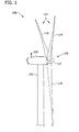
- FIG. 1 is a side elevation view of an exemplary wind turbine 100.
- wind turbine 100 is a horizontal axis wind turbine.
- wind turbine 100 may be a vertical axis wind turbine.
- Wind turbine 100 includes a tower 102 erected from a foundation (not shown), a nacelle 104 mounted on tower 102, and a rotor 108 coupled to nacelle 104.
- Rotor 108 includes a rotatable hub 110 and a plurality of rotor blades 112 coupled to and extending outwardly from hub 110.
- rotor blades 112 include a first rotor blade 114, a second rotor blade 116, and a third rotor blade 118.
- rotor 108 may include any suitable number of rotor blades 112.
- rotor blades 112 are equidistantly spaced about hub 110 to facilitate enabling kinetic energy of the wind to be converted into rotational energy and, subsequently, into electrical energy.
- rotor blades 112 may be spaced any suitable distance from one another about hub 110.
- FIG. 2 is an enlarged perspective view of nacelle 104.
- nacelle 104 includes a gear box 202, a rotor shaft 204, a high-speed shaft 206, and a generator 208.
- Rotor shaft 204 having a longitudinal axis L, rotatably couples hub 110 to gear box 202, and high-speed shaft 206 rotatably couples gear box 202 to generator 208.
- Nacelle 104 also includes a yaw drive 210 and a yaw deck 212 that facilitate adjusting a yaw of wind turbine 100, a pitch drive 214 associated with each blade 114, 116, 118 to facilitate independently adjusting a pitch of each blade 114, 116, 118, and a control system 300 that facilitates controlling an operation of wind turbine 100 (e.g., controlling an operation of pitch drive 214, yaw drive 210, etc.).
- control system 300 may be mounted at any suitable location on wind turbine 100 that enables control system 300 to function as described herein.
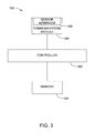
- FIG. 3 is a block diagram of an exemplary control system 300.
- control system 300 includes a controller 302, a memory 304, and a communications module 306.
- control system 300 may include any suitable device that enables control system 300 to function as described herein.
- communications module 306 includes a sensor interface 308 that facilitates enabling controller 302 to communicate with at least one sensor mounted at any suitable location on wind turbine 100.
- sensor interface 308 includes an analog-to-digital converter that converts an analog voltage signal generated by the sensors to a multi-bit digital signal usable by controller 302.
- communications module 306 may include any suitable wired and/or wireless communications device that facilitates transmitting signals to and/or receiving signals from any device located on wind turbine 100 and/or remotely from wind turbine 100.
- memory 304 may include any suitable storage device, including, but not limited to, flash memory, electronically erasable programmable memory, read only memory (ROM), removable media, and/or other volatile and non-volatile storage devices.
- executable instructions i.e., software instructions
- controller 302 in controlling wind turbine 100 (e.g., pitch drive 214), as described below.
- controller 302 is a real-time controller that includes any suitable processor-based or microprocessor-based system, such as a computer system, that includes microcontrollers, reduced instruction set circuits (RISC), application-specific integrated circuits (ASICs), logic circuits, and/or any other circuit or processor that is capable of executing the functions described herein.
- controller 302 may be a microprocessor that includes read-only memory (ROM) and/or random access memory (RAM), such as, for example, a 32 bit microcomputer with 2 Mbit ROM, and 64 Kbit RAM.
- ROM read-only memory
- RAM random access memory
- the term "real-time” refers to outcomes occurring a substantially short period of time after a change in the inputs affect the outcome, with the time period being a design parameter that may be selected based on the importance of the outcome and/or the capability of the system processing the inputs to generate the outcome.
- processor is not limited to only integrated circuits referred to in the art as a processor but broadly refers to a computer, a microcontroller, a microcomputer, a programmable logic controller, an application specific integrated circuit and any other programmable circuit.
- Figure 4 is a schematic cross-sectional view of hub 110 taken along line 4-4 (shown in Figure 2 ) with blades 114, 116, 118 coupled to hub 110.
- three mutually perpendicular axes X, Y, and Z extend through hub 110 to define a three-dimensional Cartesian coordinate system relative to a center C of hub 110.
- axis Z is coaxial with longitudinal axis L of rotor shaft 204. In other embodiments, axis Z may be oriented in any suitable direction relative to rotor shaft 204.
- a plurality of acceleration sensors 400 are mounted within hub 110 to facilitate sensing accelerations of rotor 108 in dimensions X, Y, and/or Z.
- acceleration sensors 400 include a first acceleration sensor 402 mounted with respect to (e.g., adjacent) first blade 114 to facilitate sensing a first acceleration vector A X1 of rotor 108 in dimension X, a first acceleration vector A Y1 of rotor 108 in dimension Y, and a first acceleration vector A Z1 of rotor 108 in dimension Z.
- a second acceleration sensor 404 is mounted with respect to (e.g., adjacent) second blade 116 to facilitate sensing a second acceleration vector A X2 of rotor 108 in dimension X, a second acceleration vector A Y2 of rotor 108 in dimension Y, and a second acceleration vector A Z2 of rotor 108 in dimension Z.
- a third acceleration sensor 406 is mounted with respect to (e.g., adjacent) third blade 118 to facilitate sensing a third acceleration vector A X3 of rotor 108 in dimension X, a third acceleration vector A Y3 of rotor 108 in dimension Y, and a third acceleration vector A Z3 of rotor 108 in dimension Z.
- sensed acceleration vectors A X1 , A X2 , A X3 , A Y1 , A Y2 , A Y3 , A Z1 , A Z2 , and A Z3 may have any magnitude and/or any direction, and the magnitudes and the directions shown in Figure 4 are intended to be exemplary and are not intended to limit the scope of the present invention.
- acceleration sensors 400 may be mounted at any suitable location on wind turbine 100 that enables control system 300 to function as described herein.
- acceleration sensors 402, 404, 406 are spaced a first distance D' apart from one another (i.e., substantially equidistantly apart from one another in accordance with the spacing of blades 114, 116, 118) and a second distance D" from center C (i.e., substantially equidistantly from center C and apart from rotor shaft 204).
- each acceleration sensor 402, 404, 406 may be mounted on, or adjacent to, hub 110 (e.g., each acceleration sensor 402, 404, 406 may be mounted within a separate axis box 410 associated with each blade 114, 116, 118).
- any suitable number of acceleration sensors 400 may be mounted in any suitable location within hub 110 and/or external of hub 110 that enables control system 300 to function as described herein.
- acceleration sensors 402, 404, 406 are communicatively coupled to controller 302 across any suitable wired and/or wireless communication medium via sensor interface 308 of communications module 306 to facilitate enabling acceleration sensors 402, 404, 406 to transmit signals to and/or receive signals from controller 302.
- each acceleration sensor 402, 404, 406 continuously senses accelerations of rotor 108 in all three dimensions X, Y, and Z, and each acceleration sensor 402, 404, 406 continuously transmits signals indicative of sensed acceleration vectors A X1 , A X2 , A X3 , A Y1 , A Y2 , A Y3 , A Z1 , A Z2 , and/or A Z3 to controller 302 in real-time.
- controller 302 may be programmed to continuously receive and monitor the signals transmitted by acceleration sensors 402, 404, 406.
- controller 302 may not continuously receive and/or monitor the signals transmitted by acceleration sensors 402, 404, 406 but, rather, may be programmed to iteratively request signals from acceleration sensors 402, 404, 406 at predetermined time intervals.
- controller 302 and/or acceleration sensors 402, 404, 406 may transmit signals to and/or receive signals from one another at any suitable time intervals.
- acceleration sensors 402, 404, and/or 406 may sense accelerations in any suitable number of dimensions.
- controller 302 is programmed to be calibrated when wind turbine 100 is substantially unloaded (e.g., during a non-operational state of wind turbine 100).
- controller 302 is programmed to store an unloaded position of rotor 108 (i.e., a position of rotor 108 in all three dimensions X, Y, and Z) in memory 304 and to identify the unloaded position as being a "zero" position of rotor 108.
- controller 302 After identifying the "zero" position of rotor 108 and during an operation of wind turbine 100, controller 302 is programmed to process signals received from acceleration sensors 402, 404, 406 to facilitate calculating displacements of rotor 108 from the "zero" position in all three dimensions X, Y, and Z.
- controller 302 is programmed to receive signals corresponding to sensed acceleration vectors A X1 , A Y1 , and/or A Z1 from first acceleration sensor 402, to receive signals corresponding to sensed acceleration vectors A X2 , A Y2 , and/or A Z2 from second acceleration sensor 404, and to receive signals corresponding to sensed acceleration vectors A X3 , A Y3 , and/or A Z3 from third acceleration sensor 406, and controller 302 is programmed to associate an acceleration value (i.e., a value indicative of the magnitude and/or the direction of each acceleration vector) with each received signal.
- an acceleration value i.e., a value indicative of the magnitude and/or the direction of each acceleration vector
- controller 302 is programmed to identify a rotational speed of rotor 108 in a rotational direction R and/or a rotational order of rotor 108 in dimensions X and Y (i.e., a position of each blade 114, 116, 118 in the plane defined by axes X and Y) using at least one of the acceleration values associated with sensed acceleration vectors A X1 , A X2 , A X3 , A Y1 , A Y2 , and/or A Y3 .
- controller 302 may be programmed to continuously input the acceleration values associated with sensed acceleration vectors A X1 , A X2 , A X3 , A Y1 , A Y2 , and/or A Y3 into a first mathematical model that facilitates identifying the sinusoidal acceleration pattern of rotor 108 (i.e., represented graphically as a sinusoidal acceleration curve) caused, in part, by the gravitational forces acting on rotor 108 and identifying a position of each blade 114, 116, 118 as corresponding to a particular point in the acceleration pattern (e.g., as a particular point on the sinusoidal acceleration curve).
- a first mathematical model that facilitates identifying the sinusoidal acceleration pattern of rotor 108 (i.e., represented graphically as a sinusoidal acceleration curve) caused, in part, by the gravitational forces acting on rotor 108 and identifying a position of each blade 114, 116, 118 as corresponding to a particular point in the acceleration pattern (e.g.,
- controller 302 may be programmed to identify a sinusoidal acceleration pattern 500 (represented graphically in Figure 5 as an acceleration curve 502) for blade 114 using the signals indicative of sensed accelerations A Y1, and controller 302 may also be programmed to determine that, at a point A on acceleration curve 502, blade 114 is oriented at an angle of 0° in the plane defined by axes X and Y (i.e., blade 114 is pointing straight upward) and that, at a point B on acceleration curve 502, blade 114 is oriented at an angle of 180° in the plane defmed by axes X and Y (i.e., blade 114 is pointing straight downward).
- controller 302 may be programmed to identify an acceleration pattern of any suitable number of blades and to determine a position of the blades at any suitable point in the acceleration pattern.
- controller 302 is programmed to calculate a displacement of rotor 108 from the "zero" position using the acceleration values associated with acceleration vectors A Z1 , A Z2 , and/or A Z3 .
- controller 302 is programmed to generate at least one acceleration function indicative of the acceleration vectors A Z1 , A Z2 , and/or A Z3 and the rotational order of rotor 108.
- Controller 302 is programmed to then integrate the acceleration function to express the acceleration function as a corresponding velocity function, and to subsequently integrate the velocity function to express the velocity function as a corresponding displacement function.
- controller 302 is programmed to then calculate a displacement of rotor 108 from the "zero" position to facilitate identifying loads on wind turbine 100 (i.e., loads on rotor 108, nacelle 104, and/or tower 102) at any point in time.
- controller 302 may be programmed to process any suitable number of signals associated with any suitable number of sensed acceleration vectors via any suitable mathematical model in order to facilitate identifying a load on wind turbine 100.
- controller 302 may be programmed to calculate a displacement of rotor 108 using the sensed acceleration vectors of a first predetermined group of acceleration sensors 400 and to identify the sensed acceleration vectors of a second predetermined group of acceleration sensors 400 as being redundant.
- controller 302 may be programmed to calculate a displacement using only signals received from first acceleration sensor 402 and second acceleration sensor 404 (i.e., using only acceleration vectors A X1 , A Y1 , A Z1 , A X2 , A Y2 , and/or A Z2 ).
- the signals received from third acceleration sensor 406 may be identified by controller 302 as being redundant and may be used by controller 302 in the event that first acceleration sensor 402 and/or second acceleration sensor 404 is non-operational or faulty.
- controller 302 may be programmed to calculate a displacement of rotor 108 using the sensed acceleration vectors from any suitable number of acceleration sensors 400 and to identify the signals received from any suitable number of acceleration sensors 400 as being redundant.
- controller 302 is further programmed to control at least one device of wind turbine 100 in response to an identified load on wind turbine 100 to facilitate reducing the load on wind turbine 100.
- controller 302 may be configured to control pitch drive 214 in response to an identified load on wind turbine 100 (i.e., to change a pitch of first blade 114, second blade 116, and/or third blade 118); to slow a rotation of hub 110 and/or rotor shaft 204 in response to an identified load on wind turbine 100; and/or to slow a rotation of high-speed shaft 206 in response to an identified load on wind turbine 100.
- controller 302 may be programmed to control any suitable device of wind turbine 100 to facilitate reducing a load on wind turbine 100 (e.g., to transform a load identified by controller 302 as being asymmetric into a load identified by controller 302 as being generally symmetric).
- Figure 6 is a flow chart of a method 600 of identifying a load on wind turbine 100.
- method 600 includes sensing 602 accelerations of rotor 108 in a plurality of dimensions via at least one of acceleration sensors 400; transmitting 604, from acceleration sensor 400, signals indicative of the sensed accelerations to control system 300; receiving 606, at control system 300, the transmitted signals from acceleration sensor 400; and identifying 608, via control system 300, a load on wind turbine 100 based on the received signals.
- method 600 may include any suitable step associated with facilitating an identification of a load on wind turbine 100, as described herein.
- various other suitable methods associated with facilitating identification of a load on wind turbine 100 are provided (e.g., a method of assembling a load identification system to wind turbine 100).
- the methods and systems described herein facilitate identifying a load (e.g., a thrust/bending load) on a component of a wind turbine using acceleration sensors. More specifically, the methods and systems described herein facilitate identifying a load on a rotor by sensing an acceleration of the rotor in three dimensions. As such, the methods and systems described herein facilitate minimizing the equipment used to identify dynamic loads on a rotor, thereby reducing a manufacturing cost associated with fabricating a wind turbine while increasing a reliability of the wind turbine and extending a useful life of the wind turbine.
- a load e.g., a thrust/bending load
- load identification systems are described above in detail.
- the methods and systems described herein are not limited to the specific embodiments described herein, but rather, components of the methods and systems may be utilized independently and separately from other components described herein.
- the methods and systems described herein may have other applications not limited to practice with wind turbines, as described herein. Rather, the methods and systems described herein can be implemented and utilized in connection with various other industries.
Landscapes
- Engineering & Computer Science (AREA)
- Life Sciences & Earth Sciences (AREA)
- Sustainable Development (AREA)
- Sustainable Energy (AREA)
- Chemical & Material Sciences (AREA)
- Combustion & Propulsion (AREA)
- Mechanical Engineering (AREA)
- General Engineering & Computer Science (AREA)
- Wind Motors (AREA)
Applications Claiming Priority (1)
| Application Number | Priority Date | Filing Date | Title |
|---|---|---|---|
| US12/478,871 US8222757B2 (en) | 2009-06-05 | 2009-06-05 | Load identification system and method of assembling the same |
Publications (3)
| Publication Number | Publication Date |
|---|---|
| EP2258946A2 true EP2258946A2 (de) | 2010-12-08 |
| EP2258946A3 EP2258946A3 (de) | 2014-04-09 |
| EP2258946B1 EP2258946B1 (de) | 2017-02-15 |
Family
ID=42222077
Family Applications (1)
| Application Number | Title | Priority Date | Filing Date |
|---|---|---|---|
| EP10163694.2A Active EP2258946B1 (de) | 2009-06-05 | 2010-05-24 | Lasterkennungssytem für eine Windturbine |
Country Status (4)
| Country | Link |
|---|---|
| US (1) | US8222757B2 (de) |
| EP (1) | EP2258946B1 (de) |
| CN (1) | CN101907063B (de) |
| DK (1) | DK2258946T3 (de) |
Families Citing this family (15)
| Publication number | Priority date | Publication date | Assignee | Title |
|---|---|---|---|---|
| EP2472238A1 (de) * | 2010-12-29 | 2012-07-04 | Siemens Aktiengesellschaft | Bestimmung der Vibrationsfrequenz einer Windturbinenlaufschaufel mit einer auf einer Strukturkomponente positionierten Sensorvorrichtung, die einem Teil der Laufschaufel zugeordnet und/oder Teil davon ist |
| CA2827036A1 (en) * | 2011-02-11 | 2012-08-16 | Xzeres Corp. | System and method for controlling a wind turbine including controlling yaw or other parameters |
| EP2597302B1 (de) * | 2011-11-23 | 2014-04-30 | Siemens Aktiengesellschaft | Bestimmung einer gesamten Belastung einer Windturbine in Winkelabschnitten |
| US8591187B2 (en) | 2011-12-06 | 2013-11-26 | General Electric Company | System and method for detecting loads transmitted through a blade root of a wind turbine rotor blade |
| US8757003B1 (en) | 2011-12-15 | 2014-06-24 | Shaw Shahriar Makaremi | Multi-frequency-band blade condition monitoring system |
| US8511177B1 (en) * | 2011-12-15 | 2013-08-20 | Shaw Shahriar Makaremi | Blade condition monitoring system |
| EP2607693A1 (de) * | 2011-12-22 | 2013-06-26 | Siemens Aktiengesellschaft | Verfahren und System zur Bestimmung einer mechanischen Belastung |
| US8430632B2 (en) | 2011-12-22 | 2013-04-30 | General Electric Company | System and method for pitching a rotor blade in a wind turbine |
| US10677217B2 (en) | 2012-10-03 | 2020-06-09 | General Electric Company | Wind turbine and method of operating the same |
| US9261077B2 (en) * | 2013-03-19 | 2016-02-16 | General Electric Company | System and method for real-time load control of a wind turbine |
| US9593668B2 (en) | 2013-09-10 | 2017-03-14 | General Electric Company | Methods and systems for reducing amplitude modulation in wind turbines |
| DE102013221401A1 (de) * | 2013-10-22 | 2015-04-23 | Robert Bosch Gmbh | Verfahren zur Erkennung einer Zustandsänderung einer Anlage |
| DE102014117918A1 (de) * | 2014-12-04 | 2016-06-09 | fos4X GmbH | Verfahren zur individuellen Pitchregelung von Rotorblättern einer Windkraftanlage, Beschleunigungssensor für ein Rotorblatt, Rotorblatt mit Beschleunigungssensor, ein Rotor einer Windkraftanlage und Windkraftanlagen |
| DE102014225637A1 (de) * | 2014-12-12 | 2016-06-30 | Robert Bosch Gmbh | Verfahren und Vorrichtung zum Überwachen einer Windenergieanlage |
| US10539119B2 (en) | 2017-07-10 | 2020-01-21 | WindESCo, Inc. | System and method for augmenting control of a wind turbine assembly |
Family Cites Families (28)
| Publication number | Priority date | Publication date | Assignee | Title |
|---|---|---|---|---|
| FR2732734B1 (fr) * | 1995-04-07 | 1997-06-27 | Aerospatiale | Palier magnetique miniature a au moins un axe actif |
| DK58998A (da) * | 1998-04-30 | 1999-10-31 | Lm Glasfiber As | Vindmølle |
| ES2228121T3 (es) | 1999-11-03 | 2005-04-01 | Vestas Wind Systems A/S | Procedimiento de control de la operacion de una turbina electrica y turbina electrica para usarse en dicho procedimiento. |
| DE10113038C2 (de) * | 2001-03-17 | 2003-04-10 | Aloys Wobben | Turmschwingungsüberwachung |
| CA2426711C (en) | 2002-05-02 | 2009-11-17 | General Electric Company | Wind power plant, control arrangement for a wind power plant, and method for operating a wind power plant |
| US7004724B2 (en) | 2003-02-03 | 2006-02-28 | General Electric Company | Method and apparatus for wind turbine rotor load control based on shaft radial displacement |
| US7322794B2 (en) | 2003-02-03 | 2008-01-29 | General Electric Company | Method and apparatus for condition-based monitoring of wind turbine components |
| US7160083B2 (en) | 2003-02-03 | 2007-01-09 | General Electric Company | Method and apparatus for wind turbine rotor load control |
| US6888262B2 (en) | 2003-02-03 | 2005-05-03 | General Electric Company | Method and apparatus for wind turbine rotor load control |
| US7086834B2 (en) | 2004-06-10 | 2006-08-08 | General Electric Company | Methods and apparatus for rotor blade ice detection |
| US7118339B2 (en) | 2004-06-30 | 2006-10-10 | General Electric Company | Methods and apparatus for reduction of asymmetric rotor loads in wind turbines |
| US7095129B2 (en) | 2004-06-30 | 2006-08-22 | General Electric Company | Methods and apparatus for rotor load control in wind turbines |
| DE102005034899A1 (de) * | 2005-07-26 | 2007-02-01 | Repower Systems Ag | Windenergieanlage mit Einzelpitcheinrichtungen |
| US7351033B2 (en) | 2005-09-09 | 2008-04-01 | Mcnerney Gerald | Wind turbine load control method |
| US7342323B2 (en) * | 2005-09-30 | 2008-03-11 | General Electric Company | System and method for upwind speed based control of a wind turbine |
| US7348683B2 (en) * | 2005-11-17 | 2008-03-25 | General Electric Company | Rotor for a wind energy turbine |
| JP4885570B2 (ja) * | 2006-03-03 | 2012-02-29 | ナブテスコ株式会社 | 風車用センサ機構及び風車の減振方法 |
| US7352075B2 (en) * | 2006-03-06 | 2008-04-01 | General Electric Company | Methods and apparatus for controlling rotational speed of a rotor |
| ES2348143T3 (es) | 2006-03-15 | 2010-11-30 | Siemens Aktiengesellschaft | Turbina eólica y método para determinar al menos un parámetro de rotación de un rotor de turbina eólica. |
| EP1994281B1 (de) | 2006-03-16 | 2013-05-22 | Vestas Wind Systems A/S | Verfahren und steuersystem zur verringerung von dauerbelastungen von komponenten einer windturbine, die einer asymmetrischen belastung der rotorebene ausgesetzt sind |
| US7355294B2 (en) * | 2006-05-22 | 2008-04-08 | General Electric Company | Method and system for wind turbine blade movement |
| US7437264B2 (en) | 2006-06-19 | 2008-10-14 | General Electric Company | Methods and apparatus for balancing a rotor |
| US7312537B1 (en) * | 2006-06-19 | 2007-12-25 | General Electric Company | Methods and apparatus for supplying and/or absorbing reactive power |
| JP4365394B2 (ja) | 2006-09-20 | 2009-11-18 | 株式会社日立製作所 | 風力発電システムおよびその運転方法 |
| DE102007007872B4 (de) * | 2007-02-14 | 2010-07-01 | Moog Unna Gmbh | Verfahren und Vorrichtung zur indirekten Bestimmung dynamischer Größen einer Wind- oder Wasserkraftanlage |
| DE102007008761B4 (de) * | 2007-02-22 | 2010-10-07 | Schuler Pressen Gmbh & Co. Kg | Windkraftanlage mit verspanntem Getriebe |
| WO2009001310A1 (en) | 2007-06-28 | 2008-12-31 | Danmarks Tekniske Universitet | Method and apparatus for determining the angular position of the rotor on a wind turbine |
| WO2009129617A1 (en) | 2008-04-24 | 2009-10-29 | Mike Jeffrey | A method and system for determining an imbalance of a wind turbine rotor |
-
2009
- 2009-06-05 US US12/478,871 patent/US8222757B2/en active Active
-
2010
- 2010-05-24 EP EP10163694.2A patent/EP2258946B1/de active Active
- 2010-05-24 DK DK10163694.2T patent/DK2258946T3/en active
- 2010-06-04 CN CN201010202534.4A patent/CN101907063B/zh active Active
Non-Patent Citations (1)
| Title |
|---|
| None |
Also Published As
| Publication number | Publication date |
|---|---|
| CN101907063B (zh) | 2014-10-01 |
| EP2258946B1 (de) | 2017-02-15 |
| US8222757B2 (en) | 2012-07-17 |
| US20100133814A1 (en) | 2010-06-03 |
| EP2258946A3 (de) | 2014-04-09 |
| CN101907063A (zh) | 2010-12-08 |
| DK2258946T3 (en) | 2017-03-27 |
Similar Documents
| Publication | Publication Date | Title |
|---|---|---|
| EP2258946B1 (de) | Lasterkennungssytem für eine Windturbine | |
| EP2317130B1 (de) | System und Verfahren zur Montage einer Pitch-Anordnung zur Verwendung in einer Windturbine | |
| US11242841B2 (en) | System and method for controlling a wind turbine based on a collective pitch-offset | |
| CN102767476B (zh) | 用于控制风力涡轮机推力的方法和设备 | |
| EP1906192B1 (de) | Vorrichtung zur Beurteilung von Sensoren und/oder zur Betriebssteuerung eines Geräts mit einem Sensor | |
| CN102562468B (zh) | 用于监测风力涡轮机的转子叶片的状态的系统和方法 | |
| EP2728178B1 (de) | System und verfahren zum betreiben eines windparks | |
| US8178989B2 (en) | System and methods for adjusting a yaw angle of a wind turbine | |
| EP2306007A1 (de) | Verfahren und System zur Steuerung einer Windturbine | |
| EP2327877A1 (de) | Stressanalysevorrichtung mit windmühlenstruktur, computerlesbares aufzeichnungsmedium mit darauf aufgezeichnetem stressanalyseprogramm und windkraftsystem | |
| EP2657518A2 (de) | Verfahren und Systeme zum Betrieb einer Windkraftanlage in geräuscharmer Betriebsart | |
| WO2013110215A1 (en) | Wind turbine and method for determining parameters of wind turbine | |
| EP2742235B1 (de) | Windkraftanlage und verfahren zur steuerung eines windturbinengenerators in der windkraftanlage | |
| EP4124748B1 (de) | System und verfahren zum betreiben eines windparks | |
| EP4002024B1 (de) | Systeme und verfahren zur multivariablen steuerung eines energieerzeugungssystems | |
| KR20230155964A (ko) | 풍력 터빈 제어 |
Legal Events
| Date | Code | Title | Description |
|---|---|---|---|
| PUAI | Public reference made under article 153(3) epc to a published international application that has entered the european phase |
Free format text: ORIGINAL CODE: 0009012 |
|
| AK | Designated contracting states |
Kind code of ref document: A2 Designated state(s): AL AT BE BG CH CY CZ DE DK EE ES FI FR GB GR HR HU IE IS IT LI LT LU LV MC MK MT NL NO PL PT RO SE SI SK SM TR |
|
| AX | Request for extension of the european patent |
Extension state: BA ME RS |
|
| PUAL | Search report despatched |
Free format text: ORIGINAL CODE: 0009013 |
|
| AK | Designated contracting states |
Kind code of ref document: A3 Designated state(s): AL AT BE BG CH CY CZ DE DK EE ES FI FR GB GR HR HU IE IS IT LI LT LU LV MC MK MT NL NO PL PT RO SE SI SK SM TR |
|
| AX | Request for extension of the european patent |
Extension state: BA ME RS |
|
| RIC1 | Information provided on ipc code assigned before grant |
Ipc: F03D 11/00 20060101AFI20140305BHEP |
|
| 17P | Request for examination filed |
Effective date: 20141009 |
|
| RBV | Designated contracting states (corrected) |
Designated state(s): AL AT BE BG CH CY CZ DE DK EE ES FI FR GB GR HR HU IE IS IT LI LT LU LV MC MK MT NL NO PL PT RO SE SI SK SM TR |
|
| 17Q | First examination report despatched |
Effective date: 20160330 |
|
| REG | Reference to a national code |
Ref country code: DE Ref legal event code: R079 Ref document number: 602010040058 Country of ref document: DE Free format text: PREVIOUS MAIN CLASS: F03D0011000000 Ipc: F03D0017000000 |
|
| GRAP | Despatch of communication of intention to grant a patent |
Free format text: ORIGINAL CODE: EPIDOSNIGR1 |
|
| RIC1 | Information provided on ipc code assigned before grant |
Ipc: F03D 17/00 20160101AFI20161027BHEP |
|
| INTG | Intention to grant announced |
Effective date: 20161109 |
|
| GRAS | Grant fee paid |
Free format text: ORIGINAL CODE: EPIDOSNIGR3 |
|
| GRAA | (expected) grant |
Free format text: ORIGINAL CODE: 0009210 |
|
| AK | Designated contracting states |
Kind code of ref document: B1 Designated state(s): AL AT BE BG CH CY CZ DE DK EE ES FI FR GB GR HR HU IE IS IT LI LT LU LV MC MK MT NL NO PL PT RO SE SI SK SM TR |
|
| REG | Reference to a national code |
Ref country code: CH Ref legal event code: EP Ref country code: GB Ref legal event code: FG4D |
|
| REG | Reference to a national code |
Ref country code: IE Ref legal event code: FG4D |
|
| REG | Reference to a national code |
Ref country code: AT Ref legal event code: REF Ref document number: 868071 Country of ref document: AT Kind code of ref document: T Effective date: 20170315 |
|
| REG | Reference to a national code |
Ref country code: DK Ref legal event code: T3 Effective date: 20170322 |
|
| REG | Reference to a national code |
Ref country code: DE Ref legal event code: R096 Ref document number: 602010040058 Country of ref document: DE |
|
| REG | Reference to a national code |
Ref country code: FR Ref legal event code: PLFP Year of fee payment: 8 |
|
| REG | Reference to a national code |
Ref country code: NL Ref legal event code: MP Effective date: 20170215 |
|
| REG | Reference to a national code |
Ref country code: LT Ref legal event code: MG4D |
|
| REG | Reference to a national code |
Ref country code: AT Ref legal event code: MK05 Ref document number: 868071 Country of ref document: AT Kind code of ref document: T Effective date: 20170215 |
|
| PG25 | Lapsed in a contracting state [announced via postgrant information from national office to epo] |
Ref country code: NO Free format text: LAPSE BECAUSE OF FAILURE TO SUBMIT A TRANSLATION OF THE DESCRIPTION OR TO PAY THE FEE WITHIN THE PRESCRIBED TIME-LIMIT Effective date: 20170515 Ref country code: FI Free format text: LAPSE BECAUSE OF FAILURE TO SUBMIT A TRANSLATION OF THE DESCRIPTION OR TO PAY THE FEE WITHIN THE PRESCRIBED TIME-LIMIT Effective date: 20170215 Ref country code: LT Free format text: LAPSE BECAUSE OF FAILURE TO SUBMIT A TRANSLATION OF THE DESCRIPTION OR TO PAY THE FEE WITHIN THE PRESCRIBED TIME-LIMIT Effective date: 20170215 Ref country code: HR Free format text: LAPSE BECAUSE OF FAILURE TO SUBMIT A TRANSLATION OF THE DESCRIPTION OR TO PAY THE FEE WITHIN THE PRESCRIBED TIME-LIMIT Effective date: 20170215 Ref country code: GR Free format text: LAPSE BECAUSE OF FAILURE TO SUBMIT A TRANSLATION OF THE DESCRIPTION OR TO PAY THE FEE WITHIN THE PRESCRIBED TIME-LIMIT Effective date: 20170516 |
|
| PG25 | Lapsed in a contracting state [announced via postgrant information from national office to epo] |
Ref country code: AT Free format text: LAPSE BECAUSE OF FAILURE TO SUBMIT A TRANSLATION OF THE DESCRIPTION OR TO PAY THE FEE WITHIN THE PRESCRIBED TIME-LIMIT Effective date: 20170215 Ref country code: PT Free format text: LAPSE BECAUSE OF FAILURE TO SUBMIT A TRANSLATION OF THE DESCRIPTION OR TO PAY THE FEE WITHIN THE PRESCRIBED TIME-LIMIT Effective date: 20170615 Ref country code: SE Free format text: LAPSE BECAUSE OF FAILURE TO SUBMIT A TRANSLATION OF THE DESCRIPTION OR TO PAY THE FEE WITHIN THE PRESCRIBED TIME-LIMIT Effective date: 20170215 Ref country code: LU Free format text: LAPSE BECAUSE OF NON-PAYMENT OF DUE FEES Effective date: 20170531 Ref country code: NL Free format text: LAPSE BECAUSE OF FAILURE TO SUBMIT A TRANSLATION OF THE DESCRIPTION OR TO PAY THE FEE WITHIN THE PRESCRIBED TIME-LIMIT Effective date: 20170215 Ref country code: ES Free format text: LAPSE BECAUSE OF FAILURE TO SUBMIT A TRANSLATION OF THE DESCRIPTION OR TO PAY THE FEE WITHIN THE PRESCRIBED TIME-LIMIT Effective date: 20170215 Ref country code: LV Free format text: LAPSE BECAUSE OF FAILURE TO SUBMIT A TRANSLATION OF THE DESCRIPTION OR TO PAY THE FEE WITHIN THE PRESCRIBED TIME-LIMIT Effective date: 20170215 Ref country code: BG Free format text: LAPSE BECAUSE OF FAILURE TO SUBMIT A TRANSLATION OF THE DESCRIPTION OR TO PAY THE FEE WITHIN THE PRESCRIBED TIME-LIMIT Effective date: 20170515 |
|
| PG25 | Lapsed in a contracting state [announced via postgrant information from national office to epo] |
Ref country code: SK Free format text: LAPSE BECAUSE OF FAILURE TO SUBMIT A TRANSLATION OF THE DESCRIPTION OR TO PAY THE FEE WITHIN THE PRESCRIBED TIME-LIMIT Effective date: 20170215 Ref country code: CZ Free format text: LAPSE BECAUSE OF FAILURE TO SUBMIT A TRANSLATION OF THE DESCRIPTION OR TO PAY THE FEE WITHIN THE PRESCRIBED TIME-LIMIT Effective date: 20170215 Ref country code: EE Free format text: LAPSE BECAUSE OF FAILURE TO SUBMIT A TRANSLATION OF THE DESCRIPTION OR TO PAY THE FEE WITHIN THE PRESCRIBED TIME-LIMIT Effective date: 20170215 Ref country code: IT Free format text: LAPSE BECAUSE OF FAILURE TO SUBMIT A TRANSLATION OF THE DESCRIPTION OR TO PAY THE FEE WITHIN THE PRESCRIBED TIME-LIMIT Effective date: 20170215 Ref country code: RO Free format text: LAPSE BECAUSE OF FAILURE TO SUBMIT A TRANSLATION OF THE DESCRIPTION OR TO PAY THE FEE WITHIN THE PRESCRIBED TIME-LIMIT Effective date: 20170215 |
|
| REG | Reference to a national code |
Ref country code: DE Ref legal event code: R097 Ref document number: 602010040058 Country of ref document: DE |
|
| PG25 | Lapsed in a contracting state [announced via postgrant information from national office to epo] |
Ref country code: SM Free format text: LAPSE BECAUSE OF FAILURE TO SUBMIT A TRANSLATION OF THE DESCRIPTION OR TO PAY THE FEE WITHIN THE PRESCRIBED TIME-LIMIT Effective date: 20170215 Ref country code: PL Free format text: LAPSE BECAUSE OF FAILURE TO SUBMIT A TRANSLATION OF THE DESCRIPTION OR TO PAY THE FEE WITHIN THE PRESCRIBED TIME-LIMIT Effective date: 20170215 |
|
| PLBE | No opposition filed within time limit |
Free format text: ORIGINAL CODE: 0009261 |
|
| STAA | Information on the status of an ep patent application or granted ep patent |
Free format text: STATUS: NO OPPOSITION FILED WITHIN TIME LIMIT |
|
| REG | Reference to a national code |
Ref country code: CH Ref legal event code: PL |
|
| 26N | No opposition filed |
Effective date: 20171116 |
|
| GBPC | Gb: european patent ceased through non-payment of renewal fee |
Effective date: 20170524 |
|
| PG25 | Lapsed in a contracting state [announced via postgrant information from national office to epo] |
Ref country code: MC Free format text: LAPSE BECAUSE OF FAILURE TO SUBMIT A TRANSLATION OF THE DESCRIPTION OR TO PAY THE FEE WITHIN THE PRESCRIBED TIME-LIMIT Effective date: 20170215 |
|
| REG | Reference to a national code |
Ref country code: IE Ref legal event code: MM4A |
|
| PG25 | Lapsed in a contracting state [announced via postgrant information from national office to epo] |
Ref country code: SI Free format text: LAPSE BECAUSE OF FAILURE TO SUBMIT A TRANSLATION OF THE DESCRIPTION OR TO PAY THE FEE WITHIN THE PRESCRIBED TIME-LIMIT Effective date: 20170215 Ref country code: CH Free format text: LAPSE BECAUSE OF NON-PAYMENT OF DUE FEES Effective date: 20170531 Ref country code: LI Free format text: LAPSE BECAUSE OF NON-PAYMENT OF DUE FEES Effective date: 20170531 |
|
| PG25 | Lapsed in a contracting state [announced via postgrant information from national office to epo] |
Ref country code: LU Free format text: LAPSE BECAUSE OF NON-PAYMENT OF DUE FEES Effective date: 20170524 |
|
| REG | Reference to a national code |
Ref country code: BE Ref legal event code: MM Effective date: 20170531 |
|
| PG25 | Lapsed in a contracting state [announced via postgrant information from national office to epo] |
Ref country code: IE Free format text: LAPSE BECAUSE OF NON-PAYMENT OF DUE FEES Effective date: 20170524 Ref country code: GB Free format text: LAPSE BECAUSE OF NON-PAYMENT OF DUE FEES Effective date: 20170524 |
|
| REG | Reference to a national code |
Ref country code: FR Ref legal event code: PLFP Year of fee payment: 9 |
|
| PG25 | Lapsed in a contracting state [announced via postgrant information from national office to epo] |
Ref country code: BE Free format text: LAPSE BECAUSE OF NON-PAYMENT OF DUE FEES Effective date: 20170531 |
|
| PG25 | Lapsed in a contracting state [announced via postgrant information from national office to epo] |
Ref country code: MT Free format text: LAPSE BECAUSE OF NON-PAYMENT OF DUE FEES Effective date: 20170524 |
|
| PG25 | Lapsed in a contracting state [announced via postgrant information from national office to epo] |
Ref country code: HU Free format text: LAPSE BECAUSE OF FAILURE TO SUBMIT A TRANSLATION OF THE DESCRIPTION OR TO PAY THE FEE WITHIN THE PRESCRIBED TIME-LIMIT; INVALID AB INITIO Effective date: 20100524 |
|
| PG25 | Lapsed in a contracting state [announced via postgrant information from national office to epo] |
Ref country code: CY Free format text: LAPSE BECAUSE OF NON-PAYMENT OF DUE FEES Effective date: 20170215 |
|
| PG25 | Lapsed in a contracting state [announced via postgrant information from national office to epo] |
Ref country code: MK Free format text: LAPSE BECAUSE OF FAILURE TO SUBMIT A TRANSLATION OF THE DESCRIPTION OR TO PAY THE FEE WITHIN THE PRESCRIBED TIME-LIMIT Effective date: 20170215 |
|
| PG25 | Lapsed in a contracting state [announced via postgrant information from national office to epo] |
Ref country code: AL Free format text: LAPSE BECAUSE OF FAILURE TO SUBMIT A TRANSLATION OF THE DESCRIPTION OR TO PAY THE FEE WITHIN THE PRESCRIBED TIME-LIMIT Effective date: 20170215 Ref country code: IS Free format text: LAPSE BECAUSE OF FAILURE TO SUBMIT A TRANSLATION OF THE DESCRIPTION OR TO PAY THE FEE WITHIN THE PRESCRIBED TIME-LIMIT Effective date: 20170615 |
|
| P01 | Opt-out of the competence of the unified patent court (upc) registered |
Effective date: 20230530 |
|
| REG | Reference to a national code |
Ref country code: DE Ref legal event code: R081 Ref document number: 602010040058 Country of ref document: DE Owner name: GENERAL ELECTRIC RENOVABLES ESPANA, S.L., ES Free format text: FORMER OWNER: GENERAL ELECTRIC COMPANY, SCHENECTADY, NY, US |
|
| PGFP | Annual fee paid to national office [announced via postgrant information from national office to epo] |
Ref country code: DE Payment date: 20250423 Year of fee payment: 16 |
|
| PGFP | Annual fee paid to national office [announced via postgrant information from national office to epo] |
Ref country code: DK Payment date: 20250423 Year of fee payment: 16 |
|
| PGFP | Annual fee paid to national office [announced via postgrant information from national office to epo] |
Ref country code: FR Payment date: 20250423 Year of fee payment: 16 |
|
| PGFP | Annual fee paid to national office [announced via postgrant information from national office to epo] |
Ref country code: TR Payment date: 20250429 Year of fee payment: 16 |