EP2258823A2 - Dispositif de plateau de malterie, touraille, germoir et outil de trempage - Google Patents
Dispositif de plateau de malterie, touraille, germoir et outil de trempage Download PDFInfo
- Publication number
- EP2258823A2 EP2258823A2 EP10290293A EP10290293A EP2258823A2 EP 2258823 A2 EP2258823 A2 EP 2258823A2 EP 10290293 A EP10290293 A EP 10290293A EP 10290293 A EP10290293 A EP 10290293A EP 2258823 A2 EP2258823 A2 EP 2258823A2
- Authority
- EP
- European Patent Office
- Prior art keywords
- bars
- beams
- section
- lower bars
- conveyor
- Prior art date
- Legal status (The legal status is an assumption and is not a legal conclusion. Google has not performed a legal analysis and makes no representation as to the accuracy of the status listed.)
- Granted
Links
- GXCLVBGFBYZDAG-UHFFFAOYSA-N N-[2-(1H-indol-3-yl)ethyl]-N-methylprop-2-en-1-amine Chemical compound CN(CCC1=CNC2=C1C=CC=C2)CC=C GXCLVBGFBYZDAG-UHFFFAOYSA-N 0.000 title description 12
- 238000002791 soaking Methods 0.000 claims description 14
- 229910001335 Galvanized steel Inorganic materials 0.000 claims 1
- 229910000831 Steel Inorganic materials 0.000 claims 1
- 239000008397 galvanized steel Substances 0.000 claims 1
- 239000010959 steel Substances 0.000 claims 1
- 235000013339 cereals Nutrition 0.000 description 59
- 238000009423 ventilation Methods 0.000 description 17
- 238000002513 implantation Methods 0.000 description 10
- 238000009434 installation Methods 0.000 description 9
- 238000004890 malting Methods 0.000 description 9
- 230000035784 germination Effects 0.000 description 8
- 241000209219 Hordeum Species 0.000 description 7
- 235000007340 Hordeum vulgare Nutrition 0.000 description 7
- 238000004140 cleaning Methods 0.000 description 7
- 238000010586 diagram Methods 0.000 description 7
- 238000009826 distribution Methods 0.000 description 7
- 238000004519 manufacturing process Methods 0.000 description 6
- 230000000284 resting effect Effects 0.000 description 6
- 238000005304 joining Methods 0.000 description 5
- 229910001220 stainless steel Inorganic materials 0.000 description 5
- 239000010935 stainless steel Substances 0.000 description 5
- XLYOFNOQVPJJNP-UHFFFAOYSA-N water Substances O XLYOFNOQVPJJNP-UHFFFAOYSA-N 0.000 description 5
- 238000011161 development Methods 0.000 description 3
- 230000018109 developmental process Effects 0.000 description 3
- 229910003460 diamond Inorganic materials 0.000 description 3
- 239000010432 diamond Substances 0.000 description 3
- 238000007598 dipping method Methods 0.000 description 3
- 238000001035 drying Methods 0.000 description 3
- 238000005265 energy consumption Methods 0.000 description 3
- 238000012423 maintenance Methods 0.000 description 3
- 238000000034 method Methods 0.000 description 3
- 238000011084 recovery Methods 0.000 description 3
- 230000001174 ascending effect Effects 0.000 description 2
- 239000004464 cereal grain Substances 0.000 description 2
- 239000000428 dust Substances 0.000 description 2
- 238000010438 heat treatment Methods 0.000 description 2
- 239000002184 metal Substances 0.000 description 2
- 238000012544 monitoring process Methods 0.000 description 2
- 238000005192 partition Methods 0.000 description 2
- 239000007787 solid Substances 0.000 description 2
- 229920002994 synthetic fiber Polymers 0.000 description 2
- 238000003466 welding Methods 0.000 description 2
- 239000004382 Amylase Substances 0.000 description 1
- 102000013142 Amylases Human genes 0.000 description 1
- 108010065511 Amylases Proteins 0.000 description 1
- 102000004190 Enzymes Human genes 0.000 description 1
- 108090000790 Enzymes Proteins 0.000 description 1
- 241001465754 Metazoa Species 0.000 description 1
- 108091005804 Peptidases Proteins 0.000 description 1
- 239000004365 Protease Substances 0.000 description 1
- 102100037486 Reverse transcriptase/ribonuclease H Human genes 0.000 description 1
- 241000209056 Secale Species 0.000 description 1
- 235000007238 Secale cereale Nutrition 0.000 description 1
- 240000006394 Sorghum bicolor Species 0.000 description 1
- 235000011684 Sorghum saccharatum Nutrition 0.000 description 1
- 241000826860 Trapezium Species 0.000 description 1
- 235000021307 Triticum Nutrition 0.000 description 1
- 241000209140 Triticum Species 0.000 description 1
- 238000009825 accumulation Methods 0.000 description 1
- 230000006978 adaptation Effects 0.000 description 1
- 239000000654 additive Substances 0.000 description 1
- 235000019418 amylase Nutrition 0.000 description 1
- QVGXLLKOCUKJST-UHFFFAOYSA-N atomic oxygen Chemical compound [O] QVGXLLKOCUKJST-UHFFFAOYSA-N 0.000 description 1
- 229940098396 barley grain Drugs 0.000 description 1
- 235000013405 beer Nutrition 0.000 description 1
- 238000005452 bending Methods 0.000 description 1
- 230000005540 biological transmission Effects 0.000 description 1
- 230000015572 biosynthetic process Effects 0.000 description 1
- 239000006227 byproduct Substances 0.000 description 1
- 238000002485 combustion reaction Methods 0.000 description 1
- 230000000295 complement effect Effects 0.000 description 1
- 150000001875 compounds Chemical class 0.000 description 1
- 238000010276 construction Methods 0.000 description 1
- 230000009977 dual effect Effects 0.000 description 1
- 230000000694 effects Effects 0.000 description 1
- 239000002360 explosive Substances 0.000 description 1
- 238000000855 fermentation Methods 0.000 description 1
- 230000004151 fermentation Effects 0.000 description 1
- 238000011049 filling Methods 0.000 description 1
- 239000012530 fluid Substances 0.000 description 1
- 239000012634 fragment Substances 0.000 description 1
- 230000005484 gravity Effects 0.000 description 1
- 238000011068 loading method Methods 0.000 description 1
- 230000014759 maintenance of location Effects 0.000 description 1
- 239000000463 material Substances 0.000 description 1
- 244000005700 microbiome Species 0.000 description 1
- 238000002156 mixing Methods 0.000 description 1
- 229910052760 oxygen Inorganic materials 0.000 description 1
- 239000001301 oxygen Substances 0.000 description 1
- 238000003825 pressing Methods 0.000 description 1
- 238000007639 printing Methods 0.000 description 1
- 239000000047 product Substances 0.000 description 1
- 238000010791 quenching Methods 0.000 description 1
- 230000000171 quenching effect Effects 0.000 description 1
- 230000029058 respiratory gaseous exchange Effects 0.000 description 1
- 239000002689 soil Substances 0.000 description 1
- 238000003756 stirring Methods 0.000 description 1
- 238000003860 storage Methods 0.000 description 1
- 239000000126 substance Substances 0.000 description 1
- 238000003786 synthesis reaction Methods 0.000 description 1
- 238000012549 training Methods 0.000 description 1
Images



Classifications
-
- C—CHEMISTRY; METALLURGY
- C12—BIOCHEMISTRY; BEER; SPIRITS; WINE; VINEGAR; MICROBIOLOGY; ENZYMOLOGY; MUTATION OR GENETIC ENGINEERING
- C12C—BEER; PREPARATION OF BEER BY FERMENTATION; PREPARATION OF MALT FOR MAKING BEER; PREPARATION OF HOPS FOR MAKING BEER
- C12C1/00—Preparation of malt
- C12C1/027—Germinating
- C12C1/0275—Germinating on single or multi-stage floors
-
- C—CHEMISTRY; METALLURGY
- C12—BIOCHEMISTRY; BEER; SPIRITS; WINE; VINEGAR; MICROBIOLOGY; ENZYMOLOGY; MUTATION OR GENETIC ENGINEERING
- C12C—BEER; PREPARATION OF BEER BY FERMENTATION; PREPARATION OF MALT FOR MAKING BEER; PREPARATION OF HOPS FOR MAKING BEER
- C12C1/00—Preparation of malt
- C12C1/02—Pretreatment of grains, e.g. washing, steeping
-
- C—CHEMISTRY; METALLURGY
- C12—BIOCHEMISTRY; BEER; SPIRITS; WINE; VINEGAR; MICROBIOLOGY; ENZYMOLOGY; MUTATION OR GENETIC ENGINEERING
- C12C—BEER; PREPARATION OF BEER BY FERMENTATION; PREPARATION OF MALT FOR MAKING BEER; PREPARATION OF HOPS FOR MAKING BEER
- C12C1/00—Preparation of malt
- C12C1/067—Drying
- C12C1/10—Drying on fixed supports
-
- F—MECHANICAL ENGINEERING; LIGHTING; HEATING; WEAPONS; BLASTING
- F26—DRYING
- F26B—DRYING SOLID MATERIALS OR OBJECTS BY REMOVING LIQUID THEREFROM
- F26B25/00—Details of general application not covered by group F26B21/00 or F26B23/00
- F26B25/06—Chambers, containers, or receptacles
- F26B25/08—Parts thereof
- F26B25/10—Floors, roofs, or bottoms; False bottoms
Definitions
- the invention relates to the technical field of malting.
- malting is industrial, and realized more and more in facilities called malteries.
- One of the goals of a malt house is to set up an automated facility that provides excellent performance in qualitative terms, while seeking to reduce the many investment and operating costs of this industry: land grab, civil engineering construction, energy needs, in particular.
- such an installation may comprise at least one dipping tool, at least one germoir and at least one chuck, with a transport system from one to the other, in order.
- a mill may comprise a sprouted grain tank having a tray or grid forming a bottom provided with ventilation openings.
- the kiln may include a ventilation chamber disposed under the tank.
- a ventilation system supplies the ventilation chamber with pressure air, temperature and humidity controlled. The air passes through the grate and sprouted grains resting on the tray. The plateau is a source of significant airflow losses. The same is true in a germoir or a soaking tool.
- the invention improves the situation.
- a kernel seed kernel seed dressing apparatus comprises parallel upper bars having at least one substantially horizontal upper surface, and two symmetrical side surfaces inclined with respect to a longitudinal plane, said side surfaces approximating mutually opposite the upper surface, lower bars substantially perpendicular to the upper bars having a substantially horizontal lower surface, and two symmetrical upper side surfaces and inclined with respect to a vertical plane, said upper lateral surfaces being mutually close to one another; away from the lower surface, and support beams of the lower bars, the lower bars being fixed to the upper bars and the support beams, the minimum distance between two lower bars being greater than the spacing minimum between two upper bars.
- the tray forms a grid with a high opening rate and a low risk of jamming grains. The scanning of the tray is easy. The energy consumed by the ventilation system is reduced.
- the cereal grains are first thoroughly cleaned.
- the main purpose of soaking is to bring the grain to a water content close to 50%, typically between 40 and 45%. It is also good to bring oxygen, so that the germination is just initiated or about to be out of soaking.
- Alternating or discontinuous quenching is used, with alternating periods during which the grain is under water, and others (of about half time) where the grain is exposed.
- the temperature of the water is typically 12 to 15 ° C, see 20 ° C with alternating cold water. The maximum is around 35 ° C, where the grain is likely to die.
- Various additives may be provided to prevent fermentation and development of microorganisms during soaking.
- the germination is done by placing a bed of hardened grains on a fine grid, traversed by a flow of air under controlled temperature, pressure and humidity, with brewing of the grains by means of vertical augers immersed in the bed, and driven by motors, the assembly being for example mounted on a mobile carriage that travels the sprouter.
- This cart would be an arm for a circular sprouter.
- For a rectangular sprouter it is a mobile cart on the length. The movement of the worm and the speed of movement of the truck are under control.
- the kilning is carried out on a grid, on which the grains are placed. It's about drying them to stop the germination, while keeping as much as possible the desired properties of the malt.
- the kilning is carried out in principle on a circular platform put a grid crossed by hot air, also under controlled temperature, pressure and humidity.
- a vertically adjustable leveling arm may be provided with worm immersed in the grain bed, in order to tend to homogenize it vertically or a horizontal axis screw for the equalization, loading and unloading, or fixed or adjustable blades.
- the rotational speed of the auger (s) and the direction and angular rate of advance of the arm are also controlled.
- the residence time of the grains is also controlled.
- a cleaning mechanism of the ventilation chamber may be provided with substantially parallel troughs forming the bottom of the ventilation chamber, and conveyor screws mounted in the troughs, the screws being driven by the conveyor in a direction bringing debris. fallen in a chute towards the conveyor.
- the conveyor can be mounted through the ventilation chamber to evacuate said debris during cleaning of the ventilation chamber.
- the cleaning comprises actuating the conveyor screws by the conveyor in a direction bringing debris falling into a chute towards the conveyor.
- the conveyor can be operated in one direction for cleaning and in another direction for the emptying of grains. This considerably reduces the duration and the hardness of the cleaning, in particular of the ventilation chamber.
- the figure 1 illustrates an embodiment of the installations. It shows on the right a first body of building BC1, and on the left a second body of building BC2.
- body of building BC1 are implanted several, here five, germiners G1 to G5.
- germiners G1 to G5 are implanted several, here ten, soaking tanks TR1 to TR10.
- the dip tanks are arranged in pairs at the end of each of the germiners, resulting in a reduction in the area covered, the number of buildings and the possibility of using the same conveyor to move the grain of a soaking tool to a sprouter and to move the green malt from a sprouter to a kennel, at different times.
- two slaves TA1 and TA2 In the second body of building BC2 are provided two slaves TA1 and TA2. Exhaust air from a kiln can be reused in the neighboring kiln, reducing energy consumption in heating and ventilation. In addition, the outlet air of the second kiln has at certain operating times a higher saturation rate of water vapor resulting in increased caloric capacity and better energy recovery in heat exchangers.
- Service areas are provided adjacent to the upper part of building body BC1 in BCZ1, BCZ2 and BCZ3.
- BCZ5 and BCZ6 are mainly used to recover the gaseous fluid used in the kilning, which in this example crosses the kiln from bottom to top, and is therefore recovered to the left of the figure 1 .
- Underground installations make it possible to develop the gaseous atmosphere required, on the one hand, for the germination, on the other hand, for the kilning, as well as the air required for the soaking tanks during of grain breathing phases.
- figure 2 is a perspective diagram illustrating the path of the various conveyors in the installation.
- the layout of the building is defined on the figure 2 by a dotted line fine and tight. We distinguish at the front of the BC1 building and at the back the BC2 building. Between these appears a vertical partition BC1, which delimits the two building bodies BC 1 and BC2.
- the conveyor C10 passes under the soaking tanks such as TR1, to join the lower part of the conveyor C 19, which is an ascending conveyor located near the partition BCI.
- the conveyor C19 can serve either the conveyor C20, evening the conveyor C50, both being horizontal in the upper part of the building bodies BC 1 and BC 2, respectively.
- the conveyor C20 From the conveyor C20, it leaves three conveyors C31, C32 and C33, perpendicular to the conveyor C20.
- the conveyors C31, C32 and C33 are respectively located above the germiners G1 to G3, substantially in their longitudinal symmetry.
- the arrow C319 located at the left end of the conveyor C31 indicates the quenched grain can flow into germinator G1. In fact, this spillage can be done in a controlled manner at any position of the conveyor C31 above the germinator G1, so that it can fill the latter grains substantially evenly.
- the perpendicular conveyors C31, C32 and C33 are equipped with a CR31, CR32 and CR33 discharge trolley.
- Each carriage CR31, CR32 and CR33 is arranged along the corresponding conveyor and can move continuously or between predefined working positions.
- Each carriage CR31, CR32 and CR33 includes rollers reversing the concavity of the conveyor belt as seen in cross-section, thereby causing the grain to fall.
- the band has in current section a concavity upwards in the form of ⁇ , and at the carriage a concavity down in the form of 1.
- Draining the germoirs is done from below. Sprouted grains are taken up by horizontal conveyors C41, C42 and C43, for germiners G1 to G3 respectively.
- these conveyors C41 to C43 join the conveyor C10 already mentioned.
- the sprouted grains are conveyed by this conveyor C10 to the ascending conveyor C19, this time to find the upper conveyor C50, which is followed by a horizontal perpendicular conveyor C60, to feed the clutch TA1, substantially at its center.
- the grain can also be taken up by the conveyor C61 to feed the clutch TA2, substantially in its center, instead of the clutch TA1.
- the preceding schematic diagram comprises different junctions and commutations of conveyors, which will be discussed later.
- the pits TA1 and TA2 comprise a grid.
- the kittens may comprise a plurality of grids superimposed with a mechanism for lowering the grains of a grid to a grid of a lower level.
- the kiln TA2 disposed in the building BC2 comprises an inner frame CIN defining a substantially regular polygonal substantially cylindrical space of vertical axis and a tank CV disposed in the inner frame CIN.
- the tank CV is disposed above the bottom FO building BC2.
- a GR grid or tray is arranged in the tank CV and shaped the bottom.
- a ventilation chamber CA is delimited vertically between the bottom FO and the grid GR of the tank CV and laterally by the inner frame CIN.
- the grid GR is substantially horizontal.
- the grid GR comprises a plurality of PA panels of generally rectangular shape. Each panel is provided with elongated openings configured to let the air through by retaining the grain.
- the panels PA may be formed from a perforated plate or from bars, for example welded bars crossing perpendicularly.
- the TA2 kiln is fed by conveyor C60 and conveyor C61. One end of the conveyor C61 is disposed above the tank CV.
- the grain provided by the conveyor C61 descends through a pipe C70 to reach the grid GR near the center of the kiln TA2.
- a rotating arm BR is disposed in the roll TA2 above the grid GR.
- the arm BR is rotatably mounted about a vertical axis passing through the center of the kiln TA2.
- the length of the arm BR is very slightly greater than the radius of the kiln TA2.
- the arm BR is supported in the center of the kiln TA2 by a base SO resting on the ground via poles PT. PT poles are also used to support the GR grid.
- the opposite end of the arm BR rests on a circular rail RA disposed around the grid GR.
- the arm BR is provided with grain distribution members to have a substantially regular thickness on the grid GR, for example an endless screw VS substantially horizontal axis.
- the BR arm supports the radial screw VS, see figure 1 . More precisely, the grain is discharged near the base SO through line C70, then spread outwardly by the distribution members during the rotation of the arm BR.
- the arm BR is movable in height to take into account the thickness of the grain layer in particular.
- the grain distribution members may comprise blades fixed relative to the arm or motorized mixers, for example in the form of blades or rotary screws, for stirring the grain resting on the grid GR and distribute it in substantially uniform thickness .
- the distribution elements supported by the arm BR may also be adjustable between a homogeneous distribution position of the grain during filling of the mill and an evacuation position to return the grain to the outlet after the kilning step has been carried out. .
- a top structure CSU supporting the roof T and the conveyors C60 and C61 placed under the roof T are installed.
- the conveyors C60 and C61 can be arranged in a planked passage providing access to the operators.
- the actual kilning is performed by a circulation of hot air at controlled temperature, humidity, pressure and flow.
- at least one or two fans VE are installed in the vicinity of the building BC2 in the BCZ6 service area.
- the ventilator VE receives heated and humidified air, possibly supplemented with grain treatment compounds, for example to avoid the development of undesirable substances in the grain.
- the fan VE opens under the grid GR through an opening O1 formed in the wall of building BC2.
- the air can be released into the atmosphere, possibly after energy recovery, for example by a heat exchanger, or sent to the tower TA1.
- the VE fan is controlled flow allowing an excellent adaptation to the nature of the grain and the evolution of the grain during the kilning.
- a conveyor C80 is disposed in the CA ventilation chamber of the TA2 chock for the removal of the grain after the kilning step.
- the conveyor C80 has a length greater than the diameter of the roll TA2, see figure 5 .
- the ends of the conveyor C80 arranged diametrically in the roll TA2 are arranged outside the roll TA2 and the inner frame CIN.
- the conveyor C80 comprises an endless CN conveyor chain, for example made of stainless steel with scrapers made of synthetic material, a CH chassis for example based on stainless steel, RL rollers for the return stroke, and an EN drive.
- the EN drive may comprise an electric motor in direct contact with an end roller of the conveyor chain or through a gearbox.
- the drive EN is disposed at one end of the conveyor C80 outside the kiln TA2.
- the EN training is thus easily accessible to the operators, including during the kilning operation, for easy monitoring and maintenance.
- the outdoor drive to the TA2 tower can be optimized for high reliability and / or low energy consumption instead of being optimized to meet the requirements of the atmospheric standards.
- mandatory explosives inside the TA2 kiln In addition, the end rollers subjected to the tensile stress of the conveyor belt are subject to wear and have a higher risk of heating than those common rollers carrying the conveyor chain. The arrangement of the end rollers out of the TA2 kiln also allows easy monitoring and maintenance.
- the tower TA2 may comprise a conveyor disposed under the ventilation chamber to collect the sprouted grains during unloading of the tank by said unloading orifice.
- the CV tank can be equipped with an OVG discharge port.
- the emptying of the grains after the kilning step can then be ensured by the opening of the OVG drain hole.
- the OVG drain hole may be provided with a diametral or radial hatch, a plurality of elongated hatches arranged in the GR grid above the conveyor C80, or a central hatch close to the base SO.
- the actuation of the rotating arm BR and the positioning of the grain distribution members in the emptying position can gradually return the grain to the open hatch or doors and thus empty the clutch TA2 by releasing the grid GR.
- the BR arm performs a dual function of mixing / distribution and emptying.
- the roll TA2 further comprises a plurality of chutes GL disposed substantially perpendicular to the conveyor C80.
- the chutes GL are parallel to each other.
- the chutes GL are joined edge to edge to cover the entire surface of the CA ventilation chamber of the TA2 kiln.
- the chutes GL are arranged under the grid GR and open above the conveyor chain CN of the conveyor C80.
- a chutes GL can be integrally formed by extending from one edge to the other of the internal frame CIN with an opening OVT formed in the bottom of the chute GL at the right of the conveyor C80 or be formed in two parts disjointed to the right of conveyor C80.
- the chutes GL receive during the circulation of hot air and especially during the emptying of grain to the conveyor C80, debris, dust and fragments of rootlets resulting from the drying of the grains.
- the thickness of the layer of rootlets can reach several centimeters.
- the GL chutes can be formed by a stainless steel sheet of thickness between 1 and 4 mm folded in the shape of Ve with a rounded bottom.
- GL chutes are connected to a wall of the internal frame CIN opposite the C80 conveyor, for example by a steeply inclined pan, not shown, to promote the evacuation of debris and rootlets.
- the GL chutes, in particular illustrated figure 7 have in cross section a bottom FA substantially arcuate shape and edges of ends BE substantially flat and inclined towards the edge to form a concave monotonous surface.
- the end edges BE are progressively connected to the arcuate bottom FA.
- the slope of the end edges BE is configured to facilitate the sliding of debris and rootlets downwards, that is to say towards the screw VT.
- the inclination of the end edges BE relative to the vertical may for example be less than 45 °, preferably 30 °.
- the end edges BE of two adjacent troughs connect to a sharp edge to prevent debris and rootlets remain there.
- the sharp edges of the end edges BE of the chutes GL are arranged in a substantially horizontal plane.
- the sharp edges are covered by an open PL floor, like grating, allowing access and movement of operators, including control and maintenance. Operators can enter the CA ventilation chamber through an airlock SA.
- the PL floor can be made of stainless steel.
- the floor PL may be in the form of a gate with a high opening rate and opening of much larger size, for example at least ten times, the diameter of the grains.
- the floor PL may comprise a plurality of sheet metal panels having square side openings of between 1 and 4 centimeters, separated from each other by a sheet thickness of between 1 and 4 mm, the height of the sheet being between 3 and 5 cm.
- the chutes GL are arranged horizontally or with a slight inclination towards the conveyor C80.
- Each GL chute supports a VT conveyor screw, for example in the form of a helix, with a full core AM, see figure 6 or with a hollow soul.
- the diameter of the screw VT is in agreement with the diameter of the bottom of the chute GL to ensure an effective drive to rootlets and debris fallen in the chutes GL.
- the diameter of the screw VT is between 100 mm and 250 mm depending on the depth of the corresponding chute.
- the conveyor screws VT are provided with ES support elements arranged at regular intervals in a ZIT interruption zone of the propeller.
- a support member ES may be in the form of a substantially horizontal bar bearing against the opposite walls of the chute GL.
- a support element ES may be suspended from the upper sharp edges of the trunking GL or still resting on the rounded bottom of the troughs, for example with a form of circumflex accent.
- the conveyor C80 is disposed in a hollow CX formed in the soil of the kiln TA2.
- the screws VT on either side of the center of the chute GL present a reversed pitch while being integral in rotation.
- the conveyor screw VT comprises a drive mechanism MA engaging with the conveyor C80, for example meshing with the upper part of the CN conveyor chain to the right of a support roller.
- the drive mechanism MA may comprise a wheel.
- the drive mechanism MA may comprise a freewheel.
- the freewheel ensures the transmission of the torque in one direction and transmits a zero torque in the other direction.
- the CN conveyor chain comprises connecting links and spaced wipers rubbing in the bottom of the hollow CX forming a channel.
- the scrapers may have low friction pads, for example synthetic material. The return of the CN conveyor chain takes place in the upper part of the CX trough with support rollers.
- the conveyor screw VT is driven in the direction of rotation corresponding to a movement of the rootlets and debris towards the opening OVT formed in the chute GL and can not be driven in the other direction.
- Conveyor C80 protruding by its ends beyond the TA2 kiln, cf figure 5 may be equipped with a two-way EN drive. It is thus possible, during the emptying of the grain to transport the grain in one direction, then after the emptying of the grain, during the cleaning of the TA2 kiln, to transport the rootlets and debris in the opposite direction.
- the rootlets and debris can then be stored in a suitable container, for example a silo for possible recovery, for example for the production of feed for animals or by combustion for the production of heat, particularly used to heat the air entering the TA2 kiln.
- a suitable container for example a silo for possible recovery, for example for the production of feed for animals or by combustion for the production of heat, particularly used to heat the air entering the TA2 kiln.
- the value-added product malt, on the one hand, and the by-product, in particular the smaller rootlets can thus be separated in an extremely simple manner.
- the cleaning of the TA2 kernel after the kilning phase can thus be carried out mechanically by avoiding the manual shoveling of several tons of debris and rootlets after each kilning.
- a simple scanning of the GR grid may suffice before the VT conveyor screws and the conveyor C80 are rotated in the appropriate direction.
- the grid GR partially represented in the form of a portion of a panel PA rests on beams PR arranged substantially horizontally parallel to each other.
- the beams PR are supported by the poles PT.
- the PA panel comprises a plurality of upper bars BS and a plurality of lower bars BI intersecting the upper bars BS.
- the upper bars BS are attached to the lower bars BI by a weld SD may be in the form of a weld spot or a weld seam.
- the upper bars and the lower bars on the one hand, the beams PR and the poles PT are represented at different scales, the beams PR and the poles PT having sections and spacings much higher than those of the bars.
- the GR gate can be used in a TA1, TA2, in a G1 to G5 germinator, and / or in a dipping tool T1 to T10.
- the upper bars BS are arranged in a substantially horizontal plane parallel to each other.
- the upper bars BS present, here, a cross section in the form of an isosceles triangle, for example equilateral.
- the top of the triangle is directed downwards, that is to say towards the lower bars BI.
- Each upper bar BS comprises an upper surface SSBS corresponding to the base of the triangle and two lower lateral surfaces SLBS joining toward the lower bar BI.
- the length b of the base of the triangle is chosen in particular according to the spacing e between two adjacent upper bars BS so that the opening ratio ⁇ of a GR gate is greater than 30% preferably 40%.
- the lower bars BI rest on PR beams comprising a tubular section, an upper extension EXS and a lower extension EXI.
- the EXS upper and lower EXI extensions are diametrically opposed and aligned along the tubular section.
- the EXS upper and lower EXI extensions are welded to the tubular profile.
- the EXS upper and lower EXI extensions are symmetrical and formed by a solid blade or a hollow section of rectangular section.
- the upper extension EXS is fixed, for example by bolt BL, to two lower bars BI aligned and arranged on one side and the other of the upper extension EXS.
- the upper surface of the EXS top extension is flush with the top surface of the bars lower BI.
- the lower extension EXI is fixed, for example by bolt BL, to a pole PT having a slotted upper end of complementary shape.
- the distance e between two adjacent upper bars BS is also chosen according to the size of the cereal grains in order to retain the grains while allowing the air to pass from bottom to top and the debris, dust and rootlets from top to bottom. We can choose a distance e between 1 and 3 mm.
- the triangle shape at the top bottom of the upper bars BS reduces the phenomenon of jamming debris and rootlets. Indeed, either the debris has a dimension greater than the distance e and remains on the grid GR, or the debris has a dimension smaller than the distance e and can then pass between the upper bars BS of the grid GR.
- the debris once past the zone of minimum distance between two upper bars, substantially in the plane of their upper surface is then almost assured of being able to continue its downward stroke under the effect of gravity to the extent that said space between two BS top bars are going down.
- the angle with respect to the vertical of the lower surfaces of the upper bars BS is here of the order of 35 ° to 40 °.
- the lower bars BI are arranged perpendicular to the upper bars BS and parallel to each other.
- the lower bars BI are arranged substantially perpendicular to the beams PR.
- the lower bars BI can rest on the PR beams by simply pressing their BBI bases or lower surfaces, be attached removably, for example by screws or welded.
- the lower bars BI may have a triangular section, diamond, pentagonal or other. Different sections are exposed on the figure 12 .
- the figure 12 is a cross section taken in a plane perpendicular to the section plane of the figure 8 .
- it is preferable that the lower bars BI have a spacing between them greater than the spacing e between two upper bars BS. This reduces the risk of clogging of the grid.
- the height of the lower bars BI may be greater than the height of the upper bars BS, for example by at least 50%, or even 80%.
- the lower bars BI provide grain flow surfaces, i.e., upper surfaces that avoid retaining grain.
- the upper lateral surfaces SSLBI of the lower bars BI have an inclination relative to the vertical less than or equal to 45 °, preferably less than or equal to 30 °.
- the lower bar BI comprises a peak SBI, sharp angle or small radius of curvature.
- the lower bar BI1 has an isosceles triangle-shaped section with a base resting at regular intervals on the beams PR and an apex SBI in contact at regular intervals with the upper bars BS.
- the BI1 bar has a height to base ratio greater than 60% and an angle of inclination to the vertical of the order of 35 ° to 40 °.
- the bar BI1 is welded to the beams PR and the upper bars BS.
- the bar BI2 has a section in the form of an isosceles triangle similar to the bar BI1 but with a narrower base with a height-to-base ratio of the order of 200%, ie an angle of the upper lateral surfaces SSLBI of the order of 10 ° to 15 ° with respect to the vertical.
- the lower bar BI3 is in cross section, in the form of a non-regular pentagon, symmetrical with respect to a vertical plane.
- the lower bar BI3 comprises a base BBI attached to the beam PR, two lower side surfaces and two upper side surfaces SSLBI joining to form an apex in contact with the upper bars BS.
- the angle of inclination of the upper side surfaces SSLBI can be of the order of 40 to 45 °.
- the angle of inclination of the lower surfaces is less important for grain flow and can be optimized for mechanical strength of the lower bar BI3.
- the lower bar BI4 has, in cross section, the shape of a square rhombus with a lower vertex in contact with the beams PR and an upper vertex in contact with the upper bars BS.
- the inclination of the lower and upper side surfaces SSLBI with respect to the vertical is approximately 45 °.
- the lower bar BI5 has a pentagonal section symmetrical with respect to a vertical plane with a substantially horizontal BBI base in contact with the beams PR, two substantially vertical side surfaces and two upper side surfaces SSLBI having an angle of inclination with respect to the vertical of the order of 25 to 35 °.
- the substantially vertical side surfaces facilitate the positioning of the lower bars BI5 during the production of perforated trays.
- the upper bars BS can be solid or hollow depending on their shape and the cost of the materials used. It is the same for the lower bars BI which may especially be full in the case of the BI2 bar having a relatively sharp triangular section.
- the upper bars BS have a shape similar to that of the figure 8 with, however, an inclination of the lateral surfaces SLBS with respect to the vertical of between 15 ° and 20 °.
- the opening rate is here high, of the order of 54% to 58%.
- the beams PR have a shape of diamond square or vertically elongated with a top fixed to the lower bars by a weld SD and projecting into said lower bars.
- the upper bars BS have a symmetrical pentagon shape with respect to a vertical plane with a base resting on the lower bars BI, two lower SLBS side surfaces inclined at about 15 ° to 20 ° with respect to the vertical.
- the opening rate is, here, of the order of 35% to 45%, for example equal to 40%.
- the beam PR1 is in cross section in a general shape of elongated diamond with reinforced low top. More particularly, the beam PR1 may comprise a PC hollow section whose height is at least 20% greater than the width.
- the hollow section PC is reinforced at its lower vertex by a bracket CO, for example fixed by welding.
- the angle of inclination with respect to the vertical of the upper lateral surfaces of the beam PR1 may be of the order of 35 ° to 40 °.
- the beam PR2 shown in dotted lines, has a hexagonal section symmetrical with respect to a vertical plane with flat truncation at the top.
- the beam PR2 comprises a deflector DF fixed on the flat truncation between the lower bars. DF deflectors prevent grain retention.
- the DF deflectors can be made of thin stainless steel sheet.
- the beam PR2 has two substantially vertical lateral surfaces of dimension greater than that of the other surfaces, lateral lower and lateral upper. The inclination of the upper lateral surfaces relative to the vertical may be of the order of 55 ° to 60 °.
- the beam PR3 shown in broken lines, has a pentagonal cross section symmetrical with respect to a vertical plane with a lower base and an upper vertex with flat truncation in contact with the lower bars BI.
- the upper lateral surfaces form an angle with respect to a vertical plane between 35 ° and 45 °, for example equal to 45 °.
- DF deflectors may have the same angle.
- the lower side surfaces may have an angle of the order of 10 ° to 15 ° relative to a vertical plane.
- the beam PR4 is in the form of a PC hollow tubular profile in contact with the lower bar BI.
- the deflectors DF provide lateral upper surfaces inclined by approximately 45 ° for the flow of debris and rootlets, substantially tangent with the PC section on which said deflectors DF are fixed.
- the PC profile is reinforced at its lower end by a U-section PU section substantially horizontal bottom and short vertical branches welded to the PC profile. This embodiment provides an easy connection of the lower surface of the beam PR formed by the substantially plane bottom of the profile PU to the post PT.
- the upper bars BS have a small base trapezoidal cross-section in contact with the lower bars BI.
- the opening rate is of the order of 45 to 55%.
- the spacing e between two upper bars BS is substantially equal to the length b of the large base of the trapezium forming the upper surface SSBS of the upper bar BS.
- the downwardly inclined lateral surfaces of the upper bars BS have an angle with respect to the vertical of between 10 ° and 25 °, for example equal to 18 °.
- the upper bars BS are fixed by two SD welds to the lower bar BI, one at each end of the small base. However, a large proportion, for example 50%, of these welds can be omitted.
- the beam PR5 is in the form of a tubular PC profile reinforced at its lower end by a CO angle whose wings are substantially longer than the flange of the angle of the beam PR1.
- the length of the flange of the beam CO of the beam PR5 may be greater than half the radius of the PC profile, or even 75% of the radius of the PC profile.
- Highly sloped DF deflectors are fixed on the PC profile between the lower bars BI.
- the angle can be of the order of 3 to 10 °.
- the top of the deflectors DF can be flush with the upper surface of the lower bars BI.
- the beam PR6 is in the form of a hollow profile with a pentagonal cross-section symmetrical with respect to a substantially vertical plane and having a base, two substantially vertical lateral surfaces and two upper lateral surfaces joining together in an apex in contact with the bars. lower BI.
- the upper side surfaces have an angle of between 25 ° and 45 ° relative to a vertical plane, for example of the order of 30 ° thus providing excellent downward flow of debris and other rootlets.
- a triangular wing AI is welded, on one hand on each upper lateral surface and on the other hand with the lower surface of the lower bars BI, on each side su top. An edge of the wing AI is in the extension of a substantially vertical side surface.
- the wings AI are arranged in planes substantially perpendicular to the general axis of the beam PR6.
- the lower part of the beam PR6 is clamped between two portions P1 and P2 of the post PT, for example by a bolt BL.
- the portions P1 and P2 form a groove ensuring the positioning of the beam PR6 during assembly.
- the beam PR7 comprises a hollow section PC of rectangular cross-section with two small substantially horizontal sides and two large substantially vertical sides, and deflectors DF welded to the small upper side of the hollow section PC between the lower bars BI.
- the beam PR7 is symmetrical with respect to a substantially vertical plane.
- the deflectors DF have two lateral surfaces joining at one vertex.
- the lateral surfaces have an angle of between 15 ° and 30 ° relative to a vertical plane, for example of the order of 25 °.
- the beam PR7 comprises a lower extension EX fixed to the lower surface of the PC profile.
- the lower extension EX may be in the form of a hollow profile width of between 15 and 45% of the width of the PC profile.
- the lower extension EX may be in the form of a full blade width of between 5 and 20% of the width of the PC profile.
- the lower extension EX is clamped between two portions P1 and P2 of the post PT, for example by a bolt BL.
- the portions P1 and P2 form a groove ensuring the positioning of the beam PR6 during assembly.
- the beam PR8 comprises an I-section cross section PI with two small sides substantially horizontal and a substantially vertical core, and deflectors DF welded to the small upper side of the profile PI between the lower bars.
- the PI profile can be obtained by welding plates or come monobloc manufacturing.
- the beam PR8 is symmetrical with respect to a substantially vertical plane.
- DF deflectors have two upper side surfaces joining at one vertex. The upper side surfaces have an angle of between 20 ° and 40 ° relative to a vertical plane, for example of the order of 30 °.
- the PR8 beam may comprise two additional deflectors DFS inclined to prevent the accumulation of debris on the lower side of the small profile PI, on both sides of the soul.
- the additional deflectors DFS may be welded to the core by their upper edge and on the free end of the lower small side of the profile PI by their lower edge.
- the inclination of the deflectors DF relative to the vertical may be between 10 and 30 °, for example 15 °.
- the deflectors DF may be made of thin sheet metal, for example having a thickness of between 0.5 and 2 mm.
- the additional deflectors DFS can participate significantly in the mechanical performance of the beam PR8, including bending, with a thickness close to that of the soul or that of the short sides.
- the upper bars may have a substantially trapezoidal or triangular cross section.
- the lateral surfaces of the upper bars may have an inclination relative to the vertical of between 10 ° and 50 °.
- the upper side surfaces of the lower bars may have an inclination with respect to the vertical of between 5 ° and 45 °.
- the beams may be tubular, diamond-shaped section, rectangular section or I-section.
- the device may comprise deflectors mounted along the beams.
- a sprouter can include such a device mounted above the drain members.
- a soaking tool may include such a device mounted between a bottom of the tank and a grain feed member.
Landscapes
- Engineering & Computer Science (AREA)
- Chemical & Material Sciences (AREA)
- Organic Chemistry (AREA)
- General Engineering & Computer Science (AREA)
- Bioinformatics & Cheminformatics (AREA)
- Zoology (AREA)
- Health & Medical Sciences (AREA)
- Biochemistry (AREA)
- Food Science & Technology (AREA)
- General Health & Medical Sciences (AREA)
- Genetics & Genomics (AREA)
- Life Sciences & Earth Sciences (AREA)
- Wood Science & Technology (AREA)
- Mechanical Engineering (AREA)
- Storage Of Harvested Produce (AREA)
- Drying Of Solid Materials (AREA)
- Muffle Furnaces And Rotary Kilns (AREA)
- Furnace Details (AREA)
Abstract
Description
- L'invention concerne le domaine technique de la malterie.
- Il s'agit de reproduire le développement naturel de germination d'une céréale, afin que celle-ci développe certains enzymes (notamment l'amylase, la protéase). Comme céréale on utilise généralement de l'orge, ou encore du seigle, du blé, du sorgho ou de l'épeautre. Le maltage comprend le traitement de la céréale par une succession d'opérations (notamment : trempage - germination - touraillage - dégermage), après quoi on obtient du malt. Il existe de gros besoins en malt de différentes propriétés et qualités, notamment pour la brasserie.
- Les principes généraux du maltage sont quasi ancestraux. On en trouve une synthèse dans l'ouvrage "Malterie et brasserie", de Jean SUNIER, 2ème édition, imprimerie La Concorde, Lausanne, 1968, ou encore dans sa réédition plus récente sous le nouveau titre "La Fabrication de la bière", Alliage éditeur, 26 septembre 2007, ISBN-13 No 978-2921327602.
- Aujourd'hui, le maltage est industriel, et réalisé de plus en plus dans des installations appelées malteries. L'un des buts d'une malterie est de mettre en place une installation automatisée qui procure un excellent rendement en termes qualitatifs, tout en cherchant à réduire les nombreux coûts d'investissement et de fonctionnement de cette industrie: emprise de terrain, génie civil de construction, besoins en énergie, notamment.
- De façon générale, une telle installation peut comporter au moins un outil de trempage, au moins un germoir et au moins une touraille, avec un système de transport de l'un à l'autre, dans l'ordre. Une touraille peut comprendre une cuve à grains germés comportant un plateau ou grille formant un fond muni d'ouvertures d'aération. La touraille peut comprendre une chambre de ventilation disposée sous la cuve. Un système de ventilation alimente la chambre de ventilation en air de pression, température et humidité contrôlées. L'air traverse la grille et les grains germés reposant sur le plateau. Le plateau est une source de pertes de charge aérauliques significatives. Il en va de même dans un germoir ou un outil de trempage.
- L'invention vient améliorer la situation.
- Un dispositif de plateau de touraillage de grains germés pour fond de cuve à grains germés, comprend des barres supérieures parallèles présentant au moins une surface supérieure sensiblement horizontale, et deux surfaces latérales symétriques et inclinées par rapport à un plan longitudinal, lesdites surfaces latérales se rapprochant mutuellement en allant à l'opposé de la surface supérieure, des barres inférieures sensiblement perpendiculaires aux barres supérieures présentant une surface inférieure sensiblement horizontale, et deux surfaces latérales supérieures symétriques et inclinées par rapport à un plan vertical, lesdites surfaces latérales supérieures se rapprochant mutuellement en allant à l'opposé de la surface inférieure, et des poutres de support des barres inférieures, les barres inférieures étant fixées aux barres supérieures et aux poutres de support, l'écartement minimal entre deux barres inférieures étant supérieur à l'écartement minimal entre deux barres supérieures. Le plateau forme une grille à taux d'ouverture élevé et un faible risque de coincement de grains. Le balayage du plateau est aisé. L'énergie consommée par le système de ventilation est réduite.
- D'autres caractéristiques et avantages de l'invention apparaîtront à l'examen de la description détaillée ci-après, et des dessins annexés, sur lesquels :
- la
figure 1 est, en vue de dessus, un schéma d'implantation pour un mode de réalisation particulier d'une installation de maltage, - la
figure 2 est, en vue perspective, un schéma de principe de l'implantation des convoyeurs, - la
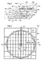
figure 3 est, en vue de dessus, un schéma d'implantation pour un mode de réalisation particulier d'une touraille, charpente et toiture omises, - la
figure 4 est, en coupe selon IV-IV de lafigure 3 , un schéma d'implantation pour un mode de réalisation particulier d'une touraille, - la
figure 5 est, en coupe selon V-V de lafigure 4 , un schéma d'implantation pour un mode de réalisation particulier d'une touraille, - la
figure 6 est, en coupe, un schéma d'implantation pour un mode de réalisation particulier de goulottes, - la
figure 7 est, en coupe, un schéma d'implantation pour un mode de réalisation particulier de transporteur de sortie de touraille, - les
figures 8 à 11 sont des vues en coupe selon un plan vertical de modes de réalisation d'une grille de touraillage ; et - la
figure 12 est une vue en coupe selon un plan vertical perpendiculaire au précédent d'un mode de réalisation d'une grille de touraillage. - Les dessins annexés pourront non seulement servir à compléter l'invention, mais aussi contribuer à sa définition, le cas échéant.
- Il est fait référence aux ouvrages "Malterie et brasserie" et/ou "La Fabrication de la bière", déjà cités, pour acquérir au besoin une connaissance générale des installations de malterie. Le maltage réalisé en malterie fait appel à des techniques complexes, et les éléments connus de l'homme du métier ne seront pas décrits en détail ici, en dehors de ce qui est directement nécessaire.
- La suite de la présente description est faite en référence à l'orge en tant que céréale.
- Abstraction faite des tâches d'intendance comme le stockage des grains d'orge, le processus de maltage comprend au moins les étapes suivantes:
- a) Un trempage des grains d'orge. Celui-ci peut se faire dans différentes sortes de cuves de trempage, que l'on appellera génériquement "outil de trempage".
- b) La germination, qui s'effectue dans des germoirs susceptibles de plusieurs modes de réalisation, notamment en raison de leur forme, qui peut être circulaire, ou au contraire semblable à un rectangle allongé. Après cette étape l'orge est qualifiée de malt vert.
- c) Le touraillage, qui est presque toujours fait dans un appareil de forme circulaire, car il s'agit de faire sécher l'orge sur une grille en le faisant traverser par de l'air chaud, tout en le retournant et/ou l'égalisant avec un bras radial. Après cette étape l'orge est qualifiée de malt.
- d) Le dégermage, qui consiste à éliminer les radicelles de l'orge.
- On donnera maintenant quelques indications générales typiques sur ces différentes étapes. Les grains de céréale sont tout d'abord soigneusement nettoyés. Le but principal du trempage est de porter le grain à une teneur en eau proche de 50 %, typiquement entre 40 et 45 %. Il est bon aussi de lui apporter de l'oxygène, de sorte que la germination soit tout juste initiée ou sur le point de l'être en sortie de trempage.
- On utilise la trempe alternée ou discontinue, avec des alternances de période pendant lesquelles le grain est sous l'eau, et d'autres (de durée environ moitié) où le grain est à découvert.
- La température de l'eau est typiquement de 12 à 15°C, voir 20°C avec alternance d'eau froide. Le maximum est autour de 35°C, où le grain risque de mourir. Différents additifs peuvent être prévus pour empêcher la fermentation et le développement de micro-organismes pendant le trempage.
- La germination se fait en plaçant un lit de grains trempés sur une grille fine, traversée par un flux d'air sous température, pression et humidité contrôlées, avec brassage des grains à l'aide de vis sans fin verticales plongeant dans le lit, et entraînées par des moteurs, l'ensemble étant par exemple monté sur un chariot mobile qui parcourt le germoir. Ce chariot serait un bras pour un germoir circulaire. Pour un germoir rectangulaire, il s'agit d'un chariot mobile sur la longueur. Le mouvement des vis sans fin et la vitesse de déplacement du chariot sont sous contrôle.
- On en vient maintenant au touraillage. Là aussi, cette opération s'effectue sur une grille, sur laquelle les grains sont posés. Il s'agit de les faire sécher pour stopper la germination, tout en gardant le mieux possible les propriétés désirées du malt. Comme son nom l'indique, le touraillage s'effectue en principe sur une plate-forme circulaire mise d'une grille traversée par de l'air chaud, également sous température, pression et humidité contrôlées. Un bras de niveau réglable verticalement peut être muni de vis sans fin plongeant dans le lit de grains, afin de tendre à l'homogénéiser verticalement ou d'une vis d'axe horizontal pour l'égalisation, le chargement et le déchargement, ou encore de pales fixes ou réglables. La vitesse de rotation de la ou des vis sans fin et le sens et la vitesse angulaire d'avancée du bras sont également contrôlées. Le temps de séjour des grains est également contrôlé.
- En outre, un mécanisme de nettoyage de la chambre de ventilation peut être pourvu de goulottes sensiblement parallèles formant le fond de la chambre de ventilation, et de vis transporteuses montées dans les goulottes, les vis étant entraînées par le convoyeur dans un sens amenant des débris tombés dans une goulotte vers le convoyeur. Le convoyeur peut être monté traversant dans la chambre de ventilation pour évacuer lesdits débris lors d'un nettoyage de la chambre de ventilation. Le nettoyage comprend l'actionnement des vis transporteuses par le convoyeur dans un sens amenant des débris tombés dans une goulotte vers le convoyeur. Le convoyeur peut être actionné dans un sens pour le nettoyage et dans un autre sens pour la vidange des grains. Ceci réduit considérablement la durée et la pénibilité du nettoyage, notamment de la chambre de ventilation.
- La
figure 1 illustre un mode de réalisation des installations. Elle fait apparaître à droite un premier corps de bâtiment BC1, et à gauche un second corps de bâtiment BC2. Dans le corps de bâtiment BC1 sont implantés plusieurs, ici cinq, germoirs G1 à G5. Dans le même corps de bâtiment, en bout des germoirs, ici au-dessous, sont implantés plusieurs, ici dix, cuves de trempage TR1 à TR10. Ici, les cuves de trempage sont disposées par paire au bout de chacun des germoirs, d'où une réduction de la surface couverte, du nombre de bâtiments et la possibilité d'utiliser un même convoyeur pour déplacer le grain d'un outil de trempage vers un germoir et pour déplacer le malt vert d'un germoir vers une touraille, à des moments différents. - Dans le second corps de bâtiment BC2 sont prévus deux tourailles TA1 et TA2. On peut réutiliser de l'air de sortie d'une touraille dans la touraille voisine, d'où une réduction de la consommation d'énergie en chauffage et en ventilation. En outre, l'air de sortie de la deuxième touraille présente à certains moments de fonctionnement un taux de saturation en vapeur d'eau plus élevé d'où une capacité calorique accrue et une meilleure récupération d'énergie dans des échangeurs de chaleur.
- Des zones de service sont prévues adjacentes à la partie supérieure du corps de bâtiment BC1, en BCZ1, BCZ2 et BCZ3.
- D'autres zones de service sont prévues en BCZ5 et BCZ6. Elles servent essentiellement à récupérer le fluide gazeux utilisé au touraillage, qui traverse dans cet exemple la touraille de bas en haut, et se voit donc récupéré vers la gauche de la
figure 1 . - Des installations de sous-sols, non représentées, permettent d'élaborer l'atmosphère gazeuse requise, d'une part, pour la germination, d'autre part, pour le touraillage, ainsi que l'air requis pour les cuves de trempage lors de phases de respiration du grain.
- Sur la
figure 1 , on distingue un convoyeur double effet C10 passant sous les cuves TR1 à TR10, ainsi que la trace d'un convoyeur C19 sur lequel on reviendra. - Il est maintenant fait référence à la
figure 2 , qui un schéma en perspective illustrant le cheminement des différents convoyeurs dans l'installation. - La disposition du bâtiment est définie sur la
figure 2 par un trait pointillé fin et serré. On distingue à l'avant le corps de bâtiment BC1 et à l'arrière le corps de bâtiment BC2. Entre ceux-ci apparaît une cloison verticale BC1, qui délimite les deux corps de bâtiment BC 1 et BC2. - Pour simplifier, une seule cuve de trempage TR1 est représentée, et de même seuls trois germoirs G1 à G3 sont représentés, au lieu des cinq de la
figure 1 . - Le convoyeur C10 passe sous les cuves de trempage telles que TR1, pour rejoindre la partie basse du convoyeur C 19, qui est un convoyeur ascensionnel situé près de la cloison BCI. A son extrémité supérieure C 199, le convoyeur C19 peut desservir soit le convoyeur C20, soir le convoyeur C50, tous deux étant horizontaux en partie haute des corps de bâtiment BC 1 et BC2, respectivement.
- Du convoyeur C20, il part trois convoyeurs C31, C32 et C33, perpendiculaires au convoyeur C20. Les convoyeurs C31, C32 et C33 sont respectivement situés au-dessus des germoirs G1 à G3, sensiblement dans leur de symétrie longitudinale. La flèche C319 située à l'extrémité gauche du convoyeur C31 indique le grain trempé peut se déverser dans germoir G1. En fait, ce déversement peut se faire de manière commandée en n'importe quelle position du convoyeur C31 au-dessus du germoir G1, de sorte que l'on puisse remplir celui-ci de grains de manière sensiblement régulière. Les convoyeurs perpendiculaires C31, C32 et C33 sont munis d'un chariot CR31, CR32 et CR33 de déversement. Chaque chariot CR31, CR32 et CR33 est disposé le long du convoyeur correspondant et peut se déplacer continument ou entre des positions de travail prédéfinies. Chaque chariot CR31, CR32 et CR33 comprend des rouleaux inversant la concavité de la bande du convoyeur vue en section transversale, faisant ainsi tomber le grain. En d'autres termes, la bande présente en section courante une concavité vers le haut en forme de □, et au niveau du chariot une concavité vers le bas en forme de 1.
- Le vidage des germoirs s'effectue par le bas. Les grains germés sont repris par des convoyeurs horizontaux C41, C42 et C43, pour les germoirs G1 à G3 respectivement.
- A leur extrémité gauche, ces convoyeurs C41 à C43 rejoignent le convoyeur C10 déjà cité. Les grains germés sont transportés par ce convoyeur C10 jusqu'au convoyeur ascensionnel C19, pour retrouver cette fois le convoyeur supérieur C50, lequel est suivi d'un convoyeur perpendiculaire horizontal C60, pour alimenter la touraille TA1, sensiblement en son centre. Le grain peut également être repris par le convoyeur C61 pour alimenter la touraille TA2, sensiblement en son centre, au lieu de la touraille TA1. Le schéma de principe qui précède comporte différentes jonctions et commutations de convoyeurs, sur lesquelles on reviendra par la suite. Dans le mode de réalisation représenté, les tourailles TA1 et TA2 comprennent une grille. Alternativement, les tourailles peuvent comprendre une pluralité de grilles superposées avec un mécanisme de descente des grains d'une grille vers une grille d'un niveau inférieur.
- Dans le mode de réalisation des
figures 3 à 5 , la touraille TA2 disposée dans le bâtiment BC2 comprend une charpente intérieure CIN définissant un espace sensiblement cylindrique polygonal régulier d'axe vertical et une cuve CV disposée dans la charpente intérieure CIN. La cuve CV est disposée au dessus du fond FO du bâtiment BC2. Une grille GR ou plateau est disposée dans la cuve CV et en forme le fond. Une chambre de ventilation CA est délimitée verticalement entre le fond FO et le grille GR de la cuve CV et latéralement par la charpente intérieure CIN. La grille GR est sensiblement horizontale. La grille GR comprend une pluralité de panneaux PA de forme générale rectangulaire. Chaque panneau est muni d'ouvertures allongées configurées pour laisser passer l'air en retenant le grain. Les panneaux PA peuvent être formés à partir d'une tôle perforée ou à partir de barreaux, par exemple de barreaux soudés se croisant perpendiculairement. La touraille TA2 est alimentée par le convoyeur C60 et le convoyeur C61. Une extrémité du convoyeur C61 est disposée au dessus de la cuve CV. - Le grain apporté par le convoyeur C61 descend par une conduite C70 pour atteindre la grille GR à proximité du centre de la touraille TA2. Un bras rotatif BR est disposé dans la touraille TA2 au-dessus de la grille GR. Le bras BR est monté à rotation autour d'un axe vertical passant par le centre de la touraille TA2. La longueur du bras BR est très légèrement supérieure au rayon de la touraille TA2. Le bras BR est supporté au centre de la touraille TA2 par un socle SO reposant sur le sol par l'intermédiaire de poteaux PT. Les poteaux PT servent également à supporter la grille GR. L'extrémité opposée du bras BR repose sur un rail circulaire RA disposé autour de la grille GR.
- Le bras BR est muni d'organes de répartition du grain permettant d'en disposer une épaisseur sensiblement régulière sur la grille GR, par exemple une vis sans fin VS d'axe sensiblement horizontal. Le bras BR supporte la vis radiale VS, voir
figure 1 . Plus précisément, le grain est déversé à proximité du socle SO par la conduite C70, puis étalé vers l'extérieur par les organes de répartition lors de la rotation du bras BR. Le bras BR est déplaçable en hauteur pour tenir compte de l'épaisseur de la couche de grains notamment. - Les organes de répartition du grain peuvent comprendre des lames fixes par rapport au bras ou des mélangeurs motorisés, par exemple sous la forme de lames ou de vis rotatives, permettant de remuer le grain reposant sur la grille GR et de le répartir en épaisseur sensiblement uniforme. Les éléments de répartition supportés par le bras BR peuvent également être orientables entre une position de répartition homogène du grain lors du remplissage de la touraille et une position d'évacuation pour ramener le grain vers la sortie après que l'étape de touraillage a été effectuée.
- Au-dessus de la touraille TA2, est installée une charpente supérieure CSU supportant la toiture T et les convoyeurs C60 et C61 disposés sous la toiture T. Les convoyeurs C60 et C61 peuvent être disposés dans un passage planchéié offrant un accès aux opérateurs.
- Le touraillage proprement dit est effectué par une circulation d'air chaud, à température, humidité, pression et débit contrôlés. A cet effet, au moins un ou deux ventilateurs VE, par exemple de type centrifuge, sont installés au voisinage du bâtiment BC2 dans la zone de service BCZ6. Le ventilateur VE reçoit de l'air chauffé et humidifié, éventuellement additionné de composés de traitement du grain, par exemple pour éviter le développement de substances indésirables dans le grain. Le ventilateur VE débouche sous la grille GR par une ouverture O1 ménagée dans le mur du bâtiment BC2. L'air circule du ventilateur VE vers la zone inférieure ou chambre de ventilation CA de la touraille TA2, traverse la grille GR, traverse la couche de grain reposant sur la grille GR passe dans une zone supérieure ZS de la touraille TA2 au dessus de la cuve CV, puis est évacué par une ouverture 02 ménagée dans une partie supérieure du mur du bâtiment BC2. En sortie, l'air peut être relâché dans l'atmosphère, éventuellement après récupération d'énergie, par exemple par un échangeur de chaleur, ou envoyé vers la touraille TA1. Le ventilateur VE est à débit commandé permettant ainsi une excellente adaptation à la nature du grain et à l'évolution du grain au cours du touraillage.
- Un convoyeur C80 est disposé dans la chambre de ventilation CA de la touraille TA2 pour l'évacuation du grain après l'étape de touraillage. Le convoyeur C80 présente une longueur supérieure au diamètre de la touraille TA2, voir
figure 5 . En d'autres termes, les extrémités du convoyeur C80 disposées diamétralement dans la touraille TA2 sont disposées à l'extérieur de la touraille TA2 et de la charpente intérieure CIN. Le convoyeur C80 comprend une chaîne transporteuse CN sans fin, par exemple en acier inoxydable avec racleurs en matériau synthétique, un châssis CH par exemple à base d'acier inoxydable, des rouleaux RL pour la course de retour, et un entraînement EN. - L'entraînement EN peut comprendre un moteur électrique en prise directe avec un rouleau d'extrémité de la chaîne transporteuse ou par l'intermédiaire d'un réducteur. L'entraînement EN est disposé à une extrémité du convoyeur C80 en dehors de la touraille TA2. L'entraînement EN est ainsi aisément accessible aux opérateurs, y compris pendant l'opération de touraillage, d'où une surveillance et une maintenance aisées. Par ailleurs, l'entraînement EN extérieur à la touraille TA2 peut être optimisé en vue d'une fiabilité élevée et/ou d'une consommation d'énergie faible au lieu d'être optimisée en vue de satisfaire aux exigences des normes relatives aux atmosphères explosives obligatoires à l'intérieur de la touraille TA2. En outre, les rouleaux d'extrémité soumis à l'effort de tension de la bande transporteuse, subissent une usure et présentent un risque d'échauffement supérieur à ceux des rouleaux courants supportant la chaîne transporteuse. La disposition des rouleaux d'extrémités hors de la touraille TA2 permet également une surveillance et une maintenance aisées.
- La touraille TA2 peut comprendre un convoyeur disposé sous la chambre de ventilation pour recueillir les grains germés lors du déchargement de la cuve par ledit orifice de déchargement.
- La cuve CV peut être munie d'un orifice de déchargement OVG. La vidange des grains après l'étape de touraillage peut alors être assurée par l'ouverture de l'orifice de vidange OVG. L'orifice de vidange OVG peut être muni d'une trappe diamétrale ou radiale, d'une pluralité de trappes allongées disposées dans la grille GR au-dessus du convoyeur C80, ou d'une trappe centrale proche du socle SO. L'actionnement du bras BR en rotation et le positionnement des organes de répartition des grains en position de vidange peut progressivement ramener le grain vers la ou les trappes ouvertes et ainsi vider la touraille TA2 en dégageant la grille GR. Le bras BR assure une double fonction de mélange/répartition et de vidange.
- La touraille TA2 comprend en outre une pluralité de goulottes GL disposées sensiblement perpendiculairement au transporteur C80. Les goulottes GL sont parallèles les unes aux autres. Les goulottes GL sont jointives bord à bord pour couvrir l'ensemble de la surface de la chambre de ventilation CA de la touraille TA2. Les goulottes GL sont disposées sous la grille GR et débouchent au-dessus de la chaîne transporteuse CN du convoyeur C80. Une goulottes GL peut être formée dé façon monobloc en s'étendant d'un bord à l'autre de la charpente intérieure CIN avec une ouverture OVT formée dans le bas de la goulotte GL au droit du convoyeur C80 ou encore être formée en deux parties disjointes au droit du convoyeur C80.
- Les goulottes GL reçoivent lors de la circulation de l'air chaud et surtout lors de la vidange des grains vers le convoyeur C80, des débris, poussières et fragments des radicelles résultant du séchage des grains. L'épaisseur de la couche de radicelles peut atteindre plusieurs centimètres. Les goulottes GL peuvent être formées par une tôle en acier inoxydable d'épaisseur comprise entre 1 et 4 mm pliée en forme de Vé à fond arrondi. Les goulottes GL se raccordent à une paroi de la charpente intérieure CIN à l'opposé du convoyeur C80, par exemple par un pan fortement incliné, non représenté, pour favoriser l'évacuation des débris et radicelles. En d'autres termes, les goulottes GL, notamment illustrées
figure 7 présentent en coupe transversale un fond FA sensiblement en forme d'arc de cercle et des bords d'extrémités BE sensiblement plans et inclinés vers le bord pour former une surface monotone concave. Les bords d'extrémités BE se raccordent progressivement au fond arqué FA. La pente des bords d'extrémité BE est configurée pour faciliter le glissement des débris et radicelles vers le bas, c'est-à-dire vers la vis VT. L'inclinaison des bords d'extrémité BE par rapport à la verticale peut par exemple être inférieure à 45°, préférablement à 30°. Les bords d'extrémités BE de deux goulottes voisines se raccordent selon une arête vive afin d'éviter que des débris et radicelles n'y restent. Les arêtes vives des bords d'extrémité BE des goulottes GL sont disposées dans un plan sensiblement horizontal. - Les arêtes vives sont recouvertes par un plancher PL ouvert, du genre caillebotis, permettant l'accès et le déplacement d'opérateurs, notamment de contrôle et de maintenance. Les opérateurs peuvent pénétrer dans la chambre de ventilation CA par un sas SA. Le plancher PL peut être réalisé en acier inoxydable. Le plancher PL peut se présenter sous la forme d'une grille à fort taux d'ouverture et à ouverture de dimension nettement supérieure, par exemple d'au moins dix fois, au diamètre des grains. A titre d'exemple, le plancher PL peut comprendre une pluralité de panneaux en tôle présentant des ouvertures carrées de côté compris entre 1 et 4 centimètres, séparées les unes des autres par une épaisseur de tôle comprise entre 1 et 4 mm, la hauteur de la tôle étant comprise entre 3 et 5 cm.
- Les goulottes GL sont disposées horizontalement ou avec une faible inclinaison en direction du convoyeur C80. Chaque goulotte GL supporte une vis transporteuse VT, par exemple en forme d'hélice, avec une âme pleine AM, voir
figure 6 ou avec une âme creuse. Le diamètre de la vis VT est en concordance avec le diamètre du fond de la goulotte GL afin d'assurer un entraînement efficace à des radicelles et débris tombés dans les goulottes GL. Le diamètre de la vis VT est compris entre 100 mm et 250 mm selon la profondeur de la goulotte correspondante. Les vis transporteuses VT sont pourvues d'éléments de support ES disposés à intervalles réguliers dans une zone d'interruption ZIT de l'hélice. Un élément de support ES peut se présenter sous la forme d'une barre sensiblement horizontale en appui contre les parois opposées de la goulotte GL. Alternativement, un élément de support ES peut être suspendu aux bords vifs supérieurs des goulottes GL ou encore en appui sur le fond arrondi des goulottes, par exemple avec une forme d'accent circonflexe. - Comme on peut le voir sur la
figure 7 , le convoyeur C80 est disposé dans un creux CX ménagé dans le sol de la touraille TA2. Les vis VT de part et d'autre du centre de la goulotte GL présentent un pas inversé tout en étant solidaires en rotation. La vis transporteuse VT comprend un mécanisme d'entraînement MA venant en prise avec le convoyeur C80, par exemple engrenant avec la partie supérieure de la chaîne transporteuse CN au droit d'un rouleau de support. Le mécanisme d'entraînement MA peut comprendre une roue. Le mécanisme d'entraînement MA peut comprendre une roue libre. La roue libre assure la transmission du couple dans un sens et transmet un couple nul dans l'autre sens. La chaîne transporteuse CN comprend des maillons de liaison et des racleurs espacés frottant dans le fond du creux CX formant un canal. Les racleurs peuvent munis de patins à faible frottement, par exemple en matériau synthétique. Le retour de la chaîne transporteuse CN s'effectue en partie haute du creux CX avec des rouleaux de support. - La vis transporteuse VT est entraînée dans le sens de rotation correspondant à un déplacement des radicelles et débris vers l'ouverture OVT ménagée dans la goulotte GL et ne peut pas être entraînée dans l'autre sens. Le convoyeur C80 en saillie par ses extrémités au-delà de la touraille TA2, cf
figure 5 , peut être muni d'un entraînement EN à deux sens de rotation. On peut ainsi, lors de la vidange du grain transporter le grain dans une direction, puis après la vidange du grain, lors du nettoyage de la touraille TA2, transporter les radicelles et débris dans la direction opposée. Les radicelles et débris peuvent ensuite être stockés dans un conteneur approprié, par exemple un silo en vue d'une valorisation éventuelle, par exemple pour la fabrication d'aliments pour les animaux ou encore par combustion en vue de produire de la chaleur, notamment utilisée pour chauffer l'air entrant dans la touraille TA2. On peut ainsi séparer de façon extrêmement simple le produit à valeur ajoutée qu'est le malt, d'une part et le sous-produit, notamment les radicelles de plus faible valeur. Le nettoyage de la touraille TA2 après la phase de touraillage peut ainsi être effectué de façon mécanisée en évitant le pelletage manuel de plusieurs tonnes de débris et radicelles après chaque touraillage. Un simple balayage de la grille GR peut suffire avant la mise en rotation des vis transporteuses VT et du convoyeur C80 dans la direction appropriée. - Dans le mode de réalisation illustré sur la
figure 8 , la grille GR représentée partiellement sous la forme d'une portion d'un panneau PA repose sur des poutres PR disposées sensiblement horizontalement parallèlement les unes aux autres. Les poutres PR sont supportées par les poteaux PT. Le panneau PA comprend une pluralité de barres supérieures BS et une pluralité de barres inférieures BI croisant les barres supérieures BS. Les barres supérieures BS sont fixées aux barres inférieures BI par une soudure SD pouvant se présenter sous la forme d'un point de soudure ou encore d'un cordon de soudure. Sur lesfigures 8 à 12 , les barres supérieures et les barres inférieures d'une part, les poutres PR et les poteaux PT sont représentés à des échelles différentes, les poutres PR et les poteaux PT ayant des sections et des espacements très supérieurs à ceux des barres. La grille GR peut servir dans une touraille TA1, TA2, dans un germoir G1 à G5, et/ou dans un outil de trempage T1 à T10. - Les barres supérieures BS sont disposées dans un plan sensiblement horizontal parallèlement les unes aux autres. Les barres supérieures BS présentent, ici, une section transversale en forme de triangle isocèle, par exemple équilatéral. Le sommet du triangle est dirigé vers le bas, c'est-à-dire vers les barres inférieures BI. Chaque barre supérieure BS comprend une surface supérieure SSBS correspondant à la base du triangle et deux surfaces latérales SLBS inférieures se rejoignant en direction de la barre inférieure BI. La longueur b de la base du triangle est choisie notamment en fonction de l'espacement e entre deux barres supérieures BS adjacentes de telle sorte que le taux d'ouverture τ d'une grille GR soit supérieur à 30 % préférablement à 40 %. Le taux d'ouverture τ peut s'exprimer par τ = e / (e + b). Dans le mode de réalisation illustré sur la
figure 8 , le taux d'ouverture τ est d'environ 33 %. On peut choisir b entre 2 et 2,5 mm, e entre 1,5 et 2,5 mm et le hauteur des barres supérieures BS entre 3 et 4 mm. - Les barres inférieures BI reposent sur des poutres PR comprenant un profilé tubulaire, une extension supérieure EXS et une extension inférieure EXI. Les extensions supérieure EXS et inférieure EXI sont diamétralement opposées et alignées le long du profilé tubulaire. Les extensions supérieure EXS et inférieure EXI sont soudées au profilé tubulaire. Les extensions supérieure EXS et inférieure EXI sont symétriques et formées par une lame pleine ou un profilé creux de section rectangulaire. L'extension supérieure EXS est fixée, par exemple par boulon BL, à deux barres inférieures BI alignées et disposées d'un côté et de l'autre de l'extension supérieure EXS. La surface supérieure de l'extension supérieure EXS affleure la surface supérieure des barres inférieures BI. L'extension inférieure EXI est fixée, par exemple par boulon BL, à un poteau PT présentant une extrémité supérieure fendue, de forme complémentaire.
- Afin de faciliter le passage de l'air et réduire les pertes de charge aérauliques et par conséquent la consommation d'énergie des ventilateurs, il est intéressant de prévoir un taux d'ouverture élevé. La distance e entre deux barres supérieures BS adjacentes est également choisie en fonction de la taille des grains de céréales afin de retenir les grains tout en laissant passer l'air de bas en haut et les débris, poussières et radicelles de haut en bas. On peut choisir une distance e comprise entre 1 et 3 mm. La forme en triangle à sommet en bas des barres supérieures BS réduit le phénomène de coincement des débris et radicelles. En effet, soit le débris présente une dimension supérieure à la distance e et reste sur la grille GR, soit le débris présente une dimension inférieure à la distance e et peut alors passer entre les barres supérieures BS de la grille GR. Le débris une fois passé la zone de distance minimale entre deux barres supérieures, sensiblement dans le plan de leur surface supérieure est alors quasiment assuré de pouvoir continuer sa course vers le bas sous l'effet de la gravité dans la mesure où ledit espace entre deux barres supérieures BS va croissant vers le bas. L'angle par rapport à la verticale des surfaces inférieures des barres supérieures BS est, ici, de l'ordre de 35° à 40 °.
- Les barres inférieures BI sont disposées perpendiculairement aux barres supérieures BS et parallèlement les unes aux autres. Les barres inférieures BI sont disposées sensiblement perpendiculairement aux poutres PR. Les barres inférieures BI peuvent reposer sur les poutres PR par simple appui de leurs bases BBI ou surfaces inférieures, y être fixées de façon amovible, par exemple par des vis ou encore soudées. Les barres inférieures BI peuvent présenter une section triangulaire, losangée, pentagonale ou autre. Différentes sections sont exposées sur la
figure 12 . Lafigure 12 est une coupe transversale prise dans un plan perpendiculaire au plan de coupe de lafigure 8 . De façon générale, il est préférable que les barres inférieures BI présentent un écartement entre elles supérieur à l'écartement e entre deux barres supérieures BS. On réduit ainsi le risque de colmatage de la grille. Préférablement, on peut prévoir une distance entre deux barres inférieures supérieure d'au moins 20 % à la distance e entre deux barres supérieures. La hauteur des barres inférieures BI peut être supérieure à la hauteur des barres supérieures BS, par exemple d'au moins 50 %, voire 80 %. - Il est également préférable que les barres inférieures BI offrent des surfaces d'écoulement des grains, c'est-à-dire des surfaces supérieures évitant de retenir du grain. A cet effet, on peut prévoir que les surfaces supérieures latérales SSLBI des barres inférieures BI présentent une inclinaison par rapport à la verticale inférieure ou égale à 45°, préférablement inférieure ou égale à 30°. A la jonction des surfaces supérieures latérales SSLBI, la barre inférieure BI comprend un sommet SBI, à angle vif ou à faible rayon de courbure.
- Sur la
figure 12 , la barre inférieure BI1 présente une section en forme de triangle isocèle avec une base reposant à intervalles réguliers sur les poutres PR et un sommet SBI en contact à intervalles réguliers avec les barres supérieures BS. La barre BI1 présente un rapport hauteur sur base supérieur à 60 % et un angle d'inclinaison par rapport à la verticale de l'ordre de 35° à 40°. La barre BI1 est soudée aux poutres PR et aux barres supérieures BS. La barre BI2 présente une section en forme de triangle isocèle analogue à la barre BI1 mais à base plus étroite avec un rapport hauteur sur base de l'ordre de 200 % soit un angle des surfaces latérales supérieures SSLBI de l'ordre de 10° à 15° par rapport à la verticale. - La barre inférieure BI3 se présente, en section transversale, sous la forme d'un pentagone non régulier, symétrique par rapport à un plan vertical. La barre inférieure BI3 comprend une base BBI fixée à la poutre PR, deux surfaces latérales inférieures et deux surfaces latérales supérieures SSLBI se rejoignant pour former un sommet en contact avec les barres supérieures BS. L'angle d'inclinaison des surfaces latérales supérieures SSLBI peut être de l'ordre de 40 à 45°. L'angle d'inclinaison des surfaces inférieures présente une moindre importance pour l'écoulement du grain et peut être optimisé en vue de la résistance mécanique de la barre inférieure BI3.
- La barre inférieure BI4 présente, en section transversale, la forme d'un losange carré avec un sommet inférieur en contact avec les poutres PR et un sommet supérieur en contact avec les barres supérieures BS. L'inclinaison des surfaces latérales inférieures et supérieures SSLBI par rapport à la verticale est de 45° environ. A titre de variante, on pourrait prévoir un losange présentant une hauteur supérieure lui conférant un angle d'inclinaison des surfaces latérales supérieures de l'ordre de 30° par rapport à la verticale.
- La barre inférieure BI5 présente une section pentagonale symétrique par rapport à un plan vertical avec une base BBI sensiblement horizontale en contact avec les poutres PR, deux surfaces latérales sensiblement verticales et deux surfaces latérales supérieures SSLBI présentant un angle d'inclinaison par rapport à la verticale de l'ordre de 25 à 35°. Les surfaces latérales sensiblement verticales facilitent le positionnement des barres inférieures BI5 lors de la fabrication des plateaux ajourés.
- Sur la
figure 12 , les croisements entre les barres inférieures et les barres supérieures et entre les barres inférieures et les poutres a été représenté comme munis de soudures. Toutefois, il est possible d'omettre une partie des soudures, notamment en les répartissant régulièrement. On peut ainsi prévoir de souder une jonction sur deux entre les barres supérieures et les barres inférieures. Il en va de même des jonctions entre les barres inférieures et les poutres et ce, d'autant plus, que les barres inférieures présentent une stabilité de par leur géométrie avec une surface plane en contact avec la surface supérieure des poutres PR, voir notamment les barres inférieures BI1, BI2, BI3 et BI5. - Les barres supérieures BS peuvent être pleines ou creuses selon leur forme et le coût des matériaux utilisés. Il en va de même des barres inférieures BI qui peuvent notamment être pleines dans le cas de la barre BI2 présentant une section triangulaire relativement pointue.
- Dans le mode de réalisation illustré sur la
figure 9 , les barres supérieures BS présentent une forme similaire à celle de lafigure 8 avec toutefois une inclinaison des surfaces latérales SLBS par rapport à la verticale comprise entre 15° et 20°. Le taux d'ouverture est, ici, élevé, de l'ordre de 54% à 58 %. Les poutres PR présentent une forme de losange carré ou allongé verticalement avec un sommet fixé aux barres inférieures par une soudure SD et en saillie dans lesdites barres inférieures. - Dans le mode de réalisation illustré sur la
figure 10 , les barres supérieures BS présentent une forme de pentagone symétrique par rapport à un plan vertical avec une base reposant sur les barres inférieures BI, deux surfaces latérales SLBS inférieures inclinées d'environ 15° à 20° par rapport à la verticale. Le taux d'ouverture est, ici, de l'ordre de 35% à 45%, par exemple égal à 40%. - Dans la partie basse de la
figure 10 , sont illustrés quatre modes de réalisation distincts des poutres PR, étant entendu qu'un panneau donné comporte ou est associé avec des poutres d'un seul mode de réalisation en règle générale. La poutre PR1 se présente en coupe transversale sous une forme générale de losange allongé à sommet bas renforcé. Plus particulièrement, la poutre PR1 peut comprendre un profilé creux PC dont la hauteur est supérieure d'au moins 20 % à la largeur. Le profilé creux PC est renforcé à son sommet inférieur par une cornière CO, par exemple fixée par soudure. L'angle d'inclinaison par rapport à la verticale des surfaces latérales supérieures de la poutre PR1 peut être de l'ordre de 35° à 40°. - La poutre PR2, représentée en pointillés, présente une section hexagonale symétrique par rapport à un plan vertical avec troncature plate au sommet supérieur. La poutre PR2 comprend un déflecteur DF fixé sur la troncature plate entre les barres inférieures. Les déflecteurs DF évitent la rétention de grains. Les déflecteurs DF peuvent être réalisés en tôle inox de faible épaisseur. La poutre PR2 présente deux surfaces latérales sensiblement verticales de dimension supérieure à celle des autres surfaces, latérales inférieures et latérales supérieures. L'inclinaison des surfaces latérales supérieures par rapport à la verticale peut être de l'ordre de 55° à 60°.
- La poutre PR3, représentée en tirets, possède une section transversale pentagonale symétrique par rapport à un plan vertical avec une base inférieure et un sommet supérieur avec troncature plate en contact avec les barres inférieures BI. Les surfaces latérales supérieures forment un angle par rapport à un plan vertical compris entre 35° et 45°, par exemple égal à 45°. Les déflecteurs DF peuvent présenter le même angle. Les surfaces latérales inférieures peuvent présenter un angle de l'ordre de 10° à 15° par rapport à un plan vertical.
- La poutre PR4 se présente sous la forme d'un profilé tubulaire creux PC en contact avec la barre inférieure BI. Les déflecteurs DF offrent des surfaces supérieures latérales inclinées d'environ 45° pour l'écoulement des débris et radicelles, sensiblement tangents avec le profilé PC sur lequel lesdits déflecteurs DF sont fixés. Le profilé PC est renforcé à son extrémité inférieure par un profilé PU à section transversale en U à fond sensiblement horizontal et courtes branches verticales soudées sur le profilé PC. Ce mode de réalisation offre un raccordement aisé de la surface inférieure de la poutre PR formée par le fond sensiblement plan du profilé PU au poteau PT.
- Dans le mode de réalisation illustré sur la
figure 11 , les barres supérieures BS présentent une section transversale en forme de trapèze à petite base en contact avec les barres inférieures BI. Le taux d'ouverture est de l'ordre de 45 à 55%. En d'autres termes, l'espacement e entre deux barres supérieures BS est sensiblement égal à la longueur b de la grande base du trapèze formant la surface supérieure SSBS de la barre supérieure BS. Les surfaces latérales inclinées vers le bas des barres supérieures BS présentent un angle par rapport à la verticale compris entre 10° et 25°, par exemple égal à 18°. Les barres supérieures BS sont fixées par deux soudures SD à la barre inférieure BI, une à chaque extrémité de la petite base. Toutefois, une forte proportion, par exemple 50%, de ces soudures peut être omise. - Quatre modes de réalisations de poutres sont représentés sur la
figure 11 . La poutre PR5 se présente sous la forme d'un profilé PC de forme tubulaire renforcé à son extrémité inférieures par une cornière CO dont les ailes sont sensiblement plus longues que les ailes de la cornière de la poutre PR1. La longueur de l'aile de la cornière CO de la poutre PR5 peut être supérieure au demi rayon du profilé PC, voire à 75% du rayon du profilé PC. Des déflecteurs DF fortement pentés sont fixés sur le profilé PC entre les barres inférieures BI. L'angle peut être de l'ordre de 3 à 10°. Le sommet des déflecteurs DFpeut affleurer la surface supérieure des barres inférieures BI. - La poutre PR6 se présente sous la forme d'un profilé creux à section transversale pentagonale symétrique par rapport à un plan sensiblement vertical et présentant une base, deux surfaces latérales sensiblement verticales et deux surfaces latérales supérieures se rejoignant en un sommet en contact avec les barres inférieures BI. Les surfaces latérales supérieures présentent un angle compris entre 25° et 45° par rapport à un plan vertical, par exemple de l'ordre de 30° offrant ainsi un excellent écoulement vers le bas des débris et autres radicelles. Une aile triangulaire AI est soudée, d'une part sur chaque surface latérale supérieure et d'autre part avec la surface inférieure des barres inférieures BI, de chaque côté su sommet. Un bord de l'aile AI est dans le prolongement d'une surface latérale sensiblement verticale. Les ailes AI sont disposées selon des plans sensiblement perpendiculaires à l'axe général de la poutre PR6. La partie inférieure de la poutre PR6 est serrée entre deux portions P1 et P2 du poteau PT, par exemple par un boulon BL. Les portions P1 et P2 forment une rainure assurant le positionnement de la poutre PR6 au montage.
- La poutre PR7 comprend d'un profilé creux PC à section transversale rectangulaire avec deux petits côtés sensiblement horizontaux et deux grands côtés sensiblement verticaux, et des déflecteurs DF soudés sur le petit côté supérieur du profilé creux PC entre les barres inférieures BI. La poutre PR7 est symétrique par rapport à un plan sensiblement vertical. Les déflecteurs DF présentent deux surfaces latérales se rejoignant en un sommet. Les surfaces latérales présentent un angle compris entre 15° et 30° par rapport à un plan vertical, par exemple de l'ordre de 25°. La poutre PR7 comprend une extension inférieure EX fixée à la surface inférieure du profilé PC. L'extension inférieure EX peut se présenter sous la forme d'un profilé creux de largeur comprise entre 15 et 45% de la largeur du profilé PC. Alternativement, l'extension inférieure EX peut se présenter sous la forme d'une lame pleine de largeur comprise entre 5 et 20% de la largeur du profilé PC. L'extension inférieure EX est serrée entre deux portions P1 et P2 du poteau PT, par exemple par un boulon BL. Les portions P1 et P2 forment une rainure assurant le positionnement de la poutre PR6 au montage.
- La poutre PR8 comprend d'un profilé PI à section transversale en I avec deux petits côtés sensiblement horizontaux et une âme sensiblement verticale, et des déflecteurs DF soudés sur le petit côté supérieur du profilé PI entre les barres inférieures. Le profilé PI peut être obtenu par soudage de plaques ou venu monobloc de fabrication. La poutre PR8 est symétrique par rapport à un plan sensiblement vertical. Les déflecteurs DF présentent deux surfaces latérales supérieures se rejoignant en un sommet. Les surfaces latérales supérieures présentent un angle compris entre 20° et 40° par rapport à un plan vertical, par exemple de l'ordre de 30°. En outre, la poutre PR8 peut comprendre deux déflecteurs supplémentaires DFS inclinés pour éviter l'accumulation de débris sur le petit côté inférieur du profilé PI, de part et d'autre de l'âme. Les déflecteurs supplémentaires DFS peuvent être soudés sur l'âme par leur bord supérieur et sur l'extrémité libre du petit côté inférieur du profilé PI par leur bord inférieur. L'inclinaison des déflecteurs DF par rapport à la verticale peut être comprise entre 10 et 30°, par exemple 15°. Les déflecteurs DF peuvent être réalisés en tôle mince, par exemple d'épaisseur comprise entre 0,5 et 2 mm. Alternativement, les déflecteurs supplémentaires DFS peuvent participer de façon significative aux performances mécaniques de la poutre PR8, notamment en flexion, avec une épaisseur voisine de celle de l'âme ou de celle des petits côtés.
- Les barres supérieures peuvent présenter une section transversale sensiblement trapézoïdale ou triangulaire. Les surfaces latérales des barres supérieures peuvent présenter une inclinaison par rapport à la verticale comprise entre 10° et 50°. Les surfaces latérales supérieures des barres inférieures peuvent présenter une inclinaison par rapport à la verticale comprise entre 5° et 45°. Les poutres peuvent être tubulaires, à section losangée, à section rectangulaire ou à section en I. Le dispositif peut comprendre des déflecteurs montés le long des poutres. Un germoir peut comprendre un tel dispositif monté au-dessus d'organes de vidange. Un outil de trempage peut comprendre un tel dispositif monté entre un fond de cuve et un organe d'amenée de grain.
- L'invention ne se limite pas aux exemples de procédé et installations ou éléments d'installation décrits ci-avant, seulement à titre d'exemple, mais elle englobe toutes les variantes que pourra envisager l'homme de l'art dans le cadre des revendications ci-après.
Claims (12)
- Dispositif de grille (GR) de touraillage de grains germés pour fond de cuve (CV) à grains germés, caractérisé en ce qu'il comprend des barres supérieures (B5) parallèles présentant au moins une surface supérieure (SSBS) sensiblement horizontale, et deux surfaces latérales (SLBS) symétriques et inclinées par rapport à un plan longitudinal, lesdites surfaces latérales se rapprochant mutuellement en allant à l'opposé de la surface supérieure, des barres inférieures (BI) sensiblement perpendiculaires aux barres supérieures (BS), deux surfaces latérales (SLBI) symétriques et inclinées par rapport à un plan vertical, lesdites surfaces latérales (SLBI) se rapprochant mutuellement en allant vers les barres supérieures (BS), et des poutres (PR) de support des barres inférieures (BI), les barres inférieures (BI) étant fixées aux barres supérieures (BS) et aux poutres de support (PR), l'écartement minimal entre deux barres inférieures (BI) étant supérieur à l'écartement minimal entre deux barres supérieures (BS).
- Dispositif selon la revendication 1, dans lequel les barres supérieures (BS) présentent une section transversale sensiblement trapézoïdale ou triangulaire.
- Dispositif selon l'une des revendications précédentes, dans lequel les barres inférieures (BI) présentent une section transversale sensiblement pentagonale, losangée ou triangulaire
- Dispositif selon l'une des revendications précédentes, dans lequel les surfaces latérales (SLBS) des barres supérieures présentent une inclinaison par rapport à la verticale comprise entre 10° et 50°.
- Dispositif selon l'une des revendications précédentes, dans lequel les surfaces latérales supérieures des barres inférieures présentent une inclinaison par rapport à la verticale comprise entre 5° et 45°.
- Dispositif selon l'une des revendications précédentes, dans lequel les poutres (PR) sont tubulaires, à section losangée, à section rectangulaire ou à section en 1.
- Dispositif selon l'une des revendications précédentes, comprenant des déflecteurs (DF) montés sur les poutres entre les barres inférieures (BI).
- Dispositif selon l'une des revendications précédentes, comprenant des déflecteurs (DFS) montés le long des poutres.
- Dispositif selon l'une des revendications précédentes, dans lequel la grille (GR) présente un taux d'ouverture supérieur à 30%, préférablement 40%.
- Touraille comprenant un dispositif selon l'une des revendications précédentes, et des goulottes (GL) réalisées en tôle d'acier galvanisé, situées sous le dispositif, et des vis (VT) réalisées en tôle d'acier galvanisé, les vis étant disposées dans les goulottes.
- Germoir comprenant un dispositif selon l'une des revendications 1 à 9, monté au dessus d'organes de vidange.
- Outil de trempage comprenant un dispositif selon l'une des revendications 1 à 9, monté entre un fond de cuve et un organe d'amenée de grains.
Priority Applications (1)
| Application Number | Priority Date | Filing Date | Title |
|---|---|---|---|
| PL10290293T PL2258823T3 (pl) | 2009-06-04 | 2010-06-03 | Urządzenie półki słodowni, suszarnia słodu, kiełkowalnia i narzędzie do moczenia |
Applications Claiming Priority (1)
| Application Number | Priority Date | Filing Date | Title |
|---|---|---|---|
| FR0902700A FR2946361B1 (fr) | 2009-06-04 | 2009-06-04 | Dispositif de plateau de malterie, touraille, germoir et outil de trempage |
Publications (3)
| Publication Number | Publication Date |
|---|---|
| EP2258823A2 true EP2258823A2 (fr) | 2010-12-08 |
| EP2258823A3 EP2258823A3 (fr) | 2012-03-21 |
| EP2258823B1 EP2258823B1 (fr) | 2013-04-24 |
Family
ID=42101329
Family Applications (1)
| Application Number | Title | Priority Date | Filing Date |
|---|---|---|---|
| EP10290293.9A Not-in-force EP2258823B1 (fr) | 2009-06-04 | 2010-06-03 | Dispositif de plateau de malterie, touraille, germoir et outil de trempage |
Country Status (6)
| Country | Link |
|---|---|
| EP (1) | EP2258823B1 (fr) |
| DK (1) | DK2258823T3 (fr) |
| ES (1) | ES2420584T3 (fr) |
| FR (1) | FR2946361B1 (fr) |
| HR (1) | HRP20130599T1 (fr) |
| PL (1) | PL2258823T3 (fr) |
Families Citing this family (1)
| Publication number | Priority date | Publication date | Assignee | Title |
|---|---|---|---|---|
| US10905143B2 (en) | 2017-08-26 | 2021-02-02 | Intelligent Malt, LLC | Granular material processor |
Family Cites Families (8)
| Publication number | Priority date | Publication date | Assignee | Title |
|---|---|---|---|---|
| BE440151A (fr) * | ||||
| US4137682A (en) * | 1977-11-29 | 1979-02-06 | Grain Systems, Inc. | Floor system for grain bin |
| US4498269A (en) * | 1981-02-18 | 1985-02-12 | Andreasen Norman H | Kiln floor system |
| DE3147671A1 (de) * | 1981-12-02 | 1983-07-14 | J.F. Nold & Co, 6081 Stockstadt | Verfahren zur herstellung von metall-horden |
| DE3232977C1 (de) * | 1982-09-04 | 1984-03-22 | Bühler-Miag GmbH, 3300 Braunschweig | Horde fuer Maelzereien und andere Gutbehandlungsraeume |
| US4619085A (en) * | 1984-02-15 | 1986-10-28 | North American Agricultural, Inc. | Grain bin floor and method of making same |
| US4943534A (en) * | 1988-09-19 | 1990-07-24 | Norman Andreasen | Tray assembly for germination floor |
| US7310919B2 (en) * | 2003-03-25 | 2007-12-25 | Ctb Ip, Inc. | Grain bin flooring system |
-
2009
- 2009-06-04 FR FR0902700A patent/FR2946361B1/fr not_active Expired - Fee Related
-
2010
- 2010-06-03 DK DK10290293.9T patent/DK2258823T3/da active
- 2010-06-03 ES ES10290293T patent/ES2420584T3/es active Active
- 2010-06-03 EP EP10290293.9A patent/EP2258823B1/fr not_active Not-in-force
- 2010-06-03 PL PL10290293T patent/PL2258823T3/pl unknown
-
2013
- 2013-06-28 HR HRP20130599AT patent/HRP20130599T1/hr unknown
Non-Patent Citations (1)
| Title |
|---|
| LA FABRICATION DE LA BIÈRE, vol. 13, 26 September 2007 (2007-09-26) |
Also Published As
| Publication number | Publication date |
|---|---|
| FR2946361B1 (fr) | 2011-06-24 |
| HRP20130599T1 (hr) | 2013-07-31 |
| EP2258823B1 (fr) | 2013-04-24 |
| FR2946361A1 (fr) | 2010-12-10 |
| EP2258823A3 (fr) | 2012-03-21 |
| PL2258823T3 (pl) | 2013-09-30 |
| DK2258823T3 (da) | 2013-07-22 |
| ES2420584T3 (es) | 2013-08-26 |
Similar Documents
| Publication | Publication Date | Title |
|---|---|---|
| US20160096695A1 (en) | Segmented bin sweep system | |
| CN109845844B (zh) | 一种青砖茶生产线及生产方法 | |
| EP2258823B1 (fr) | Dispositif de plateau de malterie, touraille, germoir et outil de trempage | |
| JP7613374B2 (ja) | 不粘着性の又は不均一な材料の塊を発酵させて均質化する装置およびその装置の操作方法 | |
| US9242792B2 (en) | Grain storage pit with curved covering grate and adjustable unloading tube | |
| EP2258827B1 (fr) | Procédé et dispositif de touraillage | |
| EP2258822B1 (fr) | Installation de malterie, et procédé correspondant | |
| WO2018193168A1 (fr) | Installation de malterie en continu | |
| EP0056202A2 (fr) | Digesteur horizontal pour la production continue de gaz méthane | |
| FR2811981A1 (fr) | Perfectionnement d'un procede de fabrication de compost | |
| CN209749665U (zh) | 一种青砖茶生产系统 | |
| EP2258826B1 (fr) | Dispositif de germoir | |
| US8567135B2 (en) | Grain storage pit | |
| EP4025527B1 (fr) | Procédé et dispositif de chargement d'un materiau en strates et installation comprenant un tel dispositif | |
| FR2972727A1 (fr) | Cuve de germination a dechargement optimise | |
| EP2258828B1 (fr) | Dispositif de touraillage de grain amélioré | |
| FR3123072A1 (fr) | Installation de malterie | |
| BE877815A (fr) | Crible cylindrique ferme stationnaire avec agitateurs rotatifs | |
| BE644652A (fr) | ||
| CN121471992A (zh) | 移动式堆糟装置 | |
| FR3122599A1 (fr) | Machine de torréfaction pour pièces de bois | |
| FR2713263A1 (fr) | Silo plat circulaire pour le stockage d'une matière pulvérulente ou granulaire. | |
| FR2678915A1 (fr) | Silo destine a stocker des produits pulverulents, granuleux ou fibreux, tels que des cereales. | |
| FR2928359A1 (fr) | "dispositif d'extraction de compost au travers d'une grille de soutenement" | |
| WO1991019685A1 (fr) | Installation pour le traitement d'une matiere premiere pulverulente telle que sulfate de calcium en vue de preparer un liant hydraulique |
Legal Events
| Date | Code | Title | Description |
|---|---|---|---|
| PUAI | Public reference made under article 153(3) epc to a published international application that has entered the european phase |
Free format text: ORIGINAL CODE: 0009012 |
|
| AK | Designated contracting states |
Kind code of ref document: A2 Designated state(s): AL AT BE BG CH CY CZ DE DK EE ES FI FR GB GR HR HU IE IS IT LI LT LU LV MC MK MT NL NO PL PT RO SE SI SK SM TR |
|
| AX | Request for extension of the european patent |
Extension state: BA ME RS |
|
| PUAL | Search report despatched |
Free format text: ORIGINAL CODE: 0009013 |
|
| AK | Designated contracting states |
Kind code of ref document: A3 Designated state(s): AL AT BE BG CH CY CZ DE DK EE ES FI FR GB GR HR HU IE IS IT LI LT LU LV MC MK MT NL NO PL PT RO SE SI SK SM TR |
|
| AX | Request for extension of the european patent |
Extension state: BA ME RS |
|
| RIC1 | Information provided on ipc code assigned before grant |
Ipc: C12C 1/02 20060101AFI20120210BHEP Ipc: C12C 1/10 20060101ALI20120210BHEP Ipc: F26B 25/10 20060101ALI20120210BHEP Ipc: C12C 1/027 20060101ALI20120210BHEP Ipc: B65D 88/74 20060101ALI20120210BHEP |
|
| 17P | Request for examination filed |
Effective date: 20120724 |
|
| GRAP | Despatch of communication of intention to grant a patent |
Free format text: ORIGINAL CODE: EPIDOSNIGR1 |
|
| GRAS | Grant fee paid |
Free format text: ORIGINAL CODE: EPIDOSNIGR3 |
|
| GRAP | Despatch of communication of intention to grant a patent |
Free format text: ORIGINAL CODE: EPIDOSNIGR1 |
|
| GRAA | (expected) grant |
Free format text: ORIGINAL CODE: 0009210 |
|
| AK | Designated contracting states |
Kind code of ref document: B1 Designated state(s): AL AT BE BG CH CY CZ DE DK EE ES FI FR GB GR HR HU IE IS IT LI LT LU LV MC MK MT NL NO PL PT RO SE SI SK SM TR |
|
| REG | Reference to a national code |
Ref country code: GB Ref legal event code: FG4D Free format text: NOT ENGLISH |
|
| REG | Reference to a national code |
Ref country code: CH Ref legal event code: EP |
|
| REG | Reference to a national code |
Ref country code: AT Ref legal event code: REF Ref document number: 608663 Country of ref document: AT Kind code of ref document: T Effective date: 20130515 |
|
| REG | Reference to a national code |
Ref country code: IE Ref legal event code: FG4D Free format text: LANGUAGE OF EP DOCUMENT: FRENCH |
|
| REG | Reference to a national code |
Ref country code: DE Ref legal event code: R096 Ref document number: 602010006548 Country of ref document: DE Effective date: 20130620 |
|
| REG | Reference to a national code |
Ref country code: HR Ref legal event code: TUEP Ref document number: P20130599 Country of ref document: HR |
|
| REG | Reference to a national code |
Ref country code: RO Ref legal event code: EPE |
|
| REG | Reference to a national code |
Ref country code: DK Ref legal event code: T3 |
|
| PGFP | Annual fee paid to national office [announced via postgrant information from national office to epo] |
Ref country code: DK Payment date: 20130621 Year of fee payment: 4 Ref country code: DE Payment date: 20130626 Year of fee payment: 4 Ref country code: IE Payment date: 20130626 Year of fee payment: 4 |
|
| REG | Reference to a national code |
Ref country code: HR Ref legal event code: T1PR Ref document number: P20130599 Country of ref document: HR |
|
| REG | Reference to a national code |
Ref country code: ES Ref legal event code: FG2A Ref document number: 2420584 Country of ref document: ES Kind code of ref document: T3 Effective date: 20130826 |
|
| REG | Reference to a national code |
Ref country code: SK Ref legal event code: T3 Ref document number: E 14307 Country of ref document: SK |
|
| REG | Reference to a national code |
Ref country code: NL Ref legal event code: T3 |
|
| REG | Reference to a national code |
Ref country code: LT Ref legal event code: MG4D |
|
| PGFP | Annual fee paid to national office [announced via postgrant information from national office to epo] |
Ref country code: BE Payment date: 20130628 Year of fee payment: 4 |
|
| REG | Reference to a national code |
Ref country code: PL Ref legal event code: T3 |
|
| PG25 | Lapsed in a contracting state [announced via postgrant information from national office to epo] |
Ref country code: NO Free format text: LAPSE BECAUSE OF FAILURE TO SUBMIT A TRANSLATION OF THE DESCRIPTION OR TO PAY THE FEE WITHIN THE PRESCRIBED TIME-LIMIT Effective date: 20130724 Ref country code: LT Free format text: LAPSE BECAUSE OF FAILURE TO SUBMIT A TRANSLATION OF THE DESCRIPTION OR TO PAY THE FEE WITHIN THE PRESCRIBED TIME-LIMIT Effective date: 20130424 Ref country code: SI Free format text: LAPSE BECAUSE OF FAILURE TO SUBMIT A TRANSLATION OF THE DESCRIPTION OR TO PAY THE FEE WITHIN THE PRESCRIBED TIME-LIMIT Effective date: 20130424 Ref country code: SE Free format text: LAPSE BECAUSE OF FAILURE TO SUBMIT A TRANSLATION OF THE DESCRIPTION OR TO PAY THE FEE WITHIN THE PRESCRIBED TIME-LIMIT Effective date: 20130424 Ref country code: IS Free format text: LAPSE BECAUSE OF FAILURE TO SUBMIT A TRANSLATION OF THE DESCRIPTION OR TO PAY THE FEE WITHIN THE PRESCRIBED TIME-LIMIT Effective date: 20130824 Ref country code: PT Free format text: LAPSE BECAUSE OF FAILURE TO SUBMIT A TRANSLATION OF THE DESCRIPTION OR TO PAY THE FEE WITHIN THE PRESCRIBED TIME-LIMIT Effective date: 20130826 Ref country code: GR Free format text: LAPSE BECAUSE OF FAILURE TO SUBMIT A TRANSLATION OF THE DESCRIPTION OR TO PAY THE FEE WITHIN THE PRESCRIBED TIME-LIMIT Effective date: 20130725 |
|
| PGFP | Annual fee paid to national office [announced via postgrant information from national office to epo] |
Ref country code: RO Payment date: 20130603 Year of fee payment: 4 Ref country code: FI Payment date: 20130729 Year of fee payment: 4 Ref country code: NL Payment date: 20130628 Year of fee payment: 4 |
|
| PG25 | Lapsed in a contracting state [announced via postgrant information from national office to epo] |
Ref country code: CY Free format text: LAPSE BECAUSE OF FAILURE TO SUBMIT A TRANSLATION OF THE DESCRIPTION OR TO PAY THE FEE WITHIN THE PRESCRIBED TIME-LIMIT Effective date: 20130424 Ref country code: LV Free format text: LAPSE BECAUSE OF FAILURE TO SUBMIT A TRANSLATION OF THE DESCRIPTION OR TO PAY THE FEE WITHIN THE PRESCRIBED TIME-LIMIT Effective date: 20130424 |
|
| PGFP | Annual fee paid to national office [announced via postgrant information from national office to epo] |
Ref country code: PL Payment date: 20130529 Year of fee payment: 4 |
|
| PGFP | Annual fee paid to national office [announced via postgrant information from national office to epo] |
Ref country code: IT Payment date: 20130630 Year of fee payment: 4 |
|
| REG | Reference to a national code |
Ref country code: HU Ref legal event code: AG4A Ref document number: E018096 Country of ref document: HU |
|
| PG25 | Lapsed in a contracting state [announced via postgrant information from national office to epo] |
Ref country code: EE Free format text: LAPSE BECAUSE OF FAILURE TO SUBMIT A TRANSLATION OF THE DESCRIPTION OR TO PAY THE FEE WITHIN THE PRESCRIBED TIME-LIMIT Effective date: 20130424 Ref country code: MC Free format text: LAPSE BECAUSE OF FAILURE TO SUBMIT A TRANSLATION OF THE DESCRIPTION OR TO PAY THE FEE WITHIN THE PRESCRIBED TIME-LIMIT Effective date: 20130424 |
|
| PGFP | Annual fee paid to national office [announced via postgrant information from national office to epo] |
Ref country code: HU Payment date: 20130824 Year of fee payment: 4 |
|
| PLBE | No opposition filed within time limit |
Free format text: ORIGINAL CODE: 0009261 |
|
| STAA | Information on the status of an ep patent application or granted ep patent |
Free format text: STATUS: NO OPPOSITION FILED WITHIN TIME LIMIT |
|
| 26N | No opposition filed |
Effective date: 20140127 |
|
| REG | Reference to a national code |
Ref country code: DE Ref legal event code: R097 Ref document number: 602010006548 Country of ref document: DE Effective date: 20140127 |
|
| REG | Reference to a national code |
Ref country code: DE Ref legal event code: R119 Ref document number: 602010006548 Country of ref document: DE |
|
| REG | Reference to a national code |
Ref country code: DK Ref legal event code: EBP Effective date: 20140630 |
|
| REG | Reference to a national code |
Ref country code: NL Ref legal event code: V1 Effective date: 20150101 |
|
| PG25 | Lapsed in a contracting state [announced via postgrant information from national office to epo] |
Ref country code: FI Free format text: LAPSE BECAUSE OF NON-PAYMENT OF DUE FEES Effective date: 20140603 Ref country code: RO Free format text: LAPSE BECAUSE OF NON-PAYMENT OF DUE FEES Effective date: 20140603 |
|
| REG | Reference to a national code |
Ref country code: CH Ref legal event code: PL |
|
| GBPC | Gb: european patent ceased through non-payment of renewal fee |
Effective date: 20140603 |
|
| PG25 | Lapsed in a contracting state [announced via postgrant information from national office to epo] |
Ref country code: MT Free format text: LAPSE BECAUSE OF FAILURE TO SUBMIT A TRANSLATION OF THE DESCRIPTION OR TO PAY THE FEE WITHIN THE PRESCRIBED TIME-LIMIT Effective date: 20130424 |
|
| REG | Reference to a national code |
Ref country code: IE Ref legal event code: MM4A |
|
| REG | Reference to a national code |
Ref country code: DE Ref legal event code: R119 Ref document number: 602010006548 Country of ref document: DE Effective date: 20150101 |
|
| PG25 | Lapsed in a contracting state [announced via postgrant information from national office to epo] |
Ref country code: NL Free format text: LAPSE BECAUSE OF NON-PAYMENT OF DUE FEES Effective date: 20150101 |
|
| PG25 | Lapsed in a contracting state [announced via postgrant information from national office to epo] |
Ref country code: CH Free format text: LAPSE BECAUSE OF NON-PAYMENT OF DUE FEES Effective date: 20140630 Ref country code: DE Free format text: LAPSE BECAUSE OF NON-PAYMENT OF DUE FEES Effective date: 20150101 Ref country code: IE Free format text: LAPSE BECAUSE OF NON-PAYMENT OF DUE FEES Effective date: 20140603 Ref country code: HU Free format text: LAPSE BECAUSE OF NON-PAYMENT OF DUE FEES Effective date: 20140604 Ref country code: IT Free format text: LAPSE BECAUSE OF NON-PAYMENT OF DUE FEES Effective date: 20140603 Ref country code: LI Free format text: LAPSE BECAUSE OF NON-PAYMENT OF DUE FEES Effective date: 20140630 |
|
| PG25 | Lapsed in a contracting state [announced via postgrant information from national office to epo] |
Ref country code: GB Free format text: LAPSE BECAUSE OF NON-PAYMENT OF DUE FEES Effective date: 20140603 Ref country code: SM Free format text: LAPSE BECAUSE OF FAILURE TO SUBMIT A TRANSLATION OF THE DESCRIPTION OR TO PAY THE FEE WITHIN THE PRESCRIBED TIME-LIMIT Effective date: 20130424 |
|
| PG25 | Lapsed in a contracting state [announced via postgrant information from national office to epo] |
Ref country code: TR Free format text: LAPSE BECAUSE OF FAILURE TO SUBMIT A TRANSLATION OF THE DESCRIPTION OR TO PAY THE FEE WITHIN THE PRESCRIBED TIME-LIMIT Effective date: 20130424 |
|
| REG | Reference to a national code |
Ref country code: ES Ref legal event code: FD2A Effective date: 20150724 |
|
| PG25 | Lapsed in a contracting state [announced via postgrant information from national office to epo] |
Ref country code: MK Free format text: LAPSE BECAUSE OF FAILURE TO SUBMIT A TRANSLATION OF THE DESCRIPTION OR TO PAY THE FEE WITHIN THE PRESCRIBED TIME-LIMIT Effective date: 20130424 Ref country code: DK Free format text: LAPSE BECAUSE OF NON-PAYMENT OF DUE FEES Effective date: 20140630 Ref country code: LU Free format text: LAPSE BECAUSE OF NON-PAYMENT OF DUE FEES Effective date: 20130603 |
|
| REG | Reference to a national code |
Ref country code: PL Ref legal event code: LAPE |
|
| PG25 | Lapsed in a contracting state [announced via postgrant information from national office to epo] |
Ref country code: ES Free format text: LAPSE BECAUSE OF NON-PAYMENT OF DUE FEES Effective date: 20140604 |
|
| PG25 | Lapsed in a contracting state [announced via postgrant information from national office to epo] |
Ref country code: PL Free format text: LAPSE BECAUSE OF NON-PAYMENT OF DUE FEES Effective date: 20140603 |
|
| REG | Reference to a national code |
Ref country code: FR Ref legal event code: PLFP Year of fee payment: 7 |
|
| REG | Reference to a national code |
Ref country code: AT Ref legal event code: MM01 Ref document number: 608663 Country of ref document: AT Kind code of ref document: T Effective date: 20150603 |
|
| PG25 | Lapsed in a contracting state [announced via postgrant information from national office to epo] |
Ref country code: AT Free format text: LAPSE BECAUSE OF NON-PAYMENT OF DUE FEES Effective date: 20150603 |
|
| REG | Reference to a national code |
Ref country code: HR Ref legal event code: ODRP Ref document number: P20130599 Country of ref document: HR Payment date: 20170601 Year of fee payment: 8 |
|
| REG | Reference to a national code |
Ref country code: FR Ref legal event code: PLFP Year of fee payment: 8 |
|
| PG25 | Lapsed in a contracting state [announced via postgrant information from national office to epo] |
Ref country code: BE Free format text: LAPSE BECAUSE OF NON-PAYMENT OF DUE FEES Effective date: 20140630 |
|
| PGFP | Annual fee paid to national office [announced via postgrant information from national office to epo] |
Ref country code: CZ Payment date: 20170531 Year of fee payment: 8 Ref country code: SK Payment date: 20170531 Year of fee payment: 8 Ref country code: HR Payment date: 20170601 Year of fee payment: 8 |
|
| PGFP | Annual fee paid to national office [announced via postgrant information from national office to epo] |
Ref country code: BG Payment date: 20170623 Year of fee payment: 8 |
|
| REG | Reference to a national code |
Ref country code: FR Ref legal event code: PLFP Year of fee payment: 9 |
|
| PG25 | Lapsed in a contracting state [announced via postgrant information from national office to epo] |
Ref country code: AL Free format text: LAPSE BECAUSE OF FAILURE TO SUBMIT A TRANSLATION OF THE DESCRIPTION OR TO PAY THE FEE WITHIN THE PRESCRIBED TIME-LIMIT Effective date: 20130424 |
|
| REG | Reference to a national code |
Ref country code: HR Ref legal event code: PBON Ref document number: P20130599 Country of ref document: HR Effective date: 20180603 |
|
| PG25 | Lapsed in a contracting state [announced via postgrant information from national office to epo] |
Ref country code: CZ Free format text: LAPSE BECAUSE OF NON-PAYMENT OF DUE FEES Effective date: 20180603 |
|
| PG25 | Lapsed in a contracting state [announced via postgrant information from national office to epo] |
Ref country code: HR Free format text: LAPSE BECAUSE OF NON-PAYMENT OF DUE FEES Effective date: 20180603 |
|
| REG | Reference to a national code |
Ref country code: SK Ref legal event code: MM4A Ref document number: E 14307 Country of ref document: SK Effective date: 20180603 |
|
| PG25 | Lapsed in a contracting state [announced via postgrant information from national office to epo] |
Ref country code: SK Free format text: LAPSE BECAUSE OF NON-PAYMENT OF DUE FEES Effective date: 20180603 |
|
| PG25 | Lapsed in a contracting state [announced via postgrant information from national office to epo] |
Ref country code: BG Free format text: LAPSE BECAUSE OF NON-PAYMENT OF DUE FEES Effective date: 20190430 |
|
| PGFP | Annual fee paid to national office [announced via postgrant information from national office to epo] |
Ref country code: FR Payment date: 20200625 Year of fee payment: 11 |
|
| PG25 | Lapsed in a contracting state [announced via postgrant information from national office to epo] |
Ref country code: FR Free format text: LAPSE BECAUSE OF NON-PAYMENT OF DUE FEES Effective date: 20210630 |