EP2258334B1 - Gastrostomy feeding apparatus and method - Google Patents
Gastrostomy feeding apparatus and method Download PDFInfo
- Publication number
- EP2258334B1 EP2258334B1 EP10005485.7A EP10005485A EP2258334B1 EP 2258334 B1 EP2258334 B1 EP 2258334B1 EP 10005485 A EP10005485 A EP 10005485A EP 2258334 B1 EP2258334 B1 EP 2258334B1
- Authority
- EP
- European Patent Office
- Prior art keywords
- tube
- bolster
- spring member
- patient
- spring
- Prior art date
- Legal status (The legal status is an assumption and is not a legal conclusion. Google has not performed a legal analysis and makes no representation as to the accuracy of the status listed.)
- Not-in-force
Links
Images



Classifications
-
- A—HUMAN NECESSITIES
- A61—MEDICAL OR VETERINARY SCIENCE; HYGIENE
- A61J—CONTAINERS SPECIALLY ADAPTED FOR MEDICAL OR PHARMACEUTICAL PURPOSES; DEVICES OR METHODS SPECIALLY ADAPTED FOR BRINGING PHARMACEUTICAL PRODUCTS INTO PARTICULAR PHYSICAL OR ADMINISTERING FORMS; DEVICES FOR ADMINISTERING FOOD OR MEDICINES ORALLY; BABY COMFORTERS; DEVICES FOR RECEIVING SPITTLE
- A61J15/00—Feeding-tubes for therapeutic purposes
- A61J15/0026—Parts, details or accessories for feeding-tubes
- A61J15/0053—Means for fixing the tube outside of the body, e.g. by a special shape, by fixing it to the skin
- A61J15/0065—Fixing means and tube being one part
-
- A—HUMAN NECESSITIES
- A61—MEDICAL OR VETERINARY SCIENCE; HYGIENE
- A61J—CONTAINERS SPECIALLY ADAPTED FOR MEDICAL OR PHARMACEUTICAL PURPOSES; DEVICES OR METHODS SPECIALLY ADAPTED FOR BRINGING PHARMACEUTICAL PRODUCTS INTO PARTICULAR PHYSICAL OR ADMINISTERING FORMS; DEVICES FOR ADMINISTERING FOOD OR MEDICINES ORALLY; BABY COMFORTERS; DEVICES FOR RECEIVING SPITTLE
- A61J15/00—Feeding-tubes for therapeutic purposes
- A61J15/0015—Gastrostomy feeding-tubes
-
- A—HUMAN NECESSITIES
- A61—MEDICAL OR VETERINARY SCIENCE; HYGIENE
- A61J—CONTAINERS SPECIALLY ADAPTED FOR MEDICAL OR PHARMACEUTICAL PURPOSES; DEVICES OR METHODS SPECIALLY ADAPTED FOR BRINGING PHARMACEUTICAL PRODUCTS INTO PARTICULAR PHYSICAL OR ADMINISTERING FORMS; DEVICES FOR ADMINISTERING FOOD OR MEDICINES ORALLY; BABY COMFORTERS; DEVICES FOR RECEIVING SPITTLE
- A61J15/00—Feeding-tubes for therapeutic purposes
- A61J15/0026—Parts, details or accessories for feeding-tubes
-
- A—HUMAN NECESSITIES
- A61—MEDICAL OR VETERINARY SCIENCE; HYGIENE
- A61J—CONTAINERS SPECIALLY ADAPTED FOR MEDICAL OR PHARMACEUTICAL PURPOSES; DEVICES OR METHODS SPECIALLY ADAPTED FOR BRINGING PHARMACEUTICAL PRODUCTS INTO PARTICULAR PHYSICAL OR ADMINISTERING FORMS; DEVICES FOR ADMINISTERING FOOD OR MEDICINES ORALLY; BABY COMFORTERS; DEVICES FOR RECEIVING SPITTLE
- A61J15/00—Feeding-tubes for therapeutic purposes
- A61J15/0026—Parts, details or accessories for feeding-tubes
- A61J15/003—Means for fixing the tube inside the body, e.g. balloons, retaining means
- A61J15/0034—Retainers adjacent to a body opening to prevent that the tube slips through, e.g. bolsters
- A61J15/0038—Retainers adjacent to a body opening to prevent that the tube slips through, e.g. bolsters expandable, e.g. umbrella type
-
- A—HUMAN NECESSITIES
- A61—MEDICAL OR VETERINARY SCIENCE; HYGIENE
- A61M—DEVICES FOR INTRODUCING MEDIA INTO, OR ONTO, THE BODY; DEVICES FOR TRANSDUCING BODY MEDIA OR FOR TAKING MEDIA FROM THE BODY; DEVICES FOR PRODUCING OR ENDING SLEEP OR STUPOR
- A61M39/00—Tubes, tube connectors, tube couplings, valves, access sites or the like, specially adapted for medical use
- A61M39/02—Access sites
- A61M39/0208—Subcutaneous access sites
- A61M2039/0223—Subcutaneous access sites having means for anchoring the subcutaneous access site
-
- A—HUMAN NECESSITIES
- A61—MEDICAL OR VETERINARY SCIENCE; HYGIENE
- A61M—DEVICES FOR INTRODUCING MEDIA INTO, OR ONTO, THE BODY; DEVICES FOR TRANSDUCING BODY MEDIA OR FOR TAKING MEDIA FROM THE BODY; DEVICES FOR PRODUCING OR ENDING SLEEP OR STUPOR
- A61M39/00—Tubes, tube connectors, tube couplings, valves, access sites or the like, specially adapted for medical use
- A61M39/02—Access sites
- A61M39/0247—Transcutaneous or percutaneous access sites to the inside of the body
- A61M2039/0255—Transcutaneous or percutaneous access sites to the inside of the body for access to the gastric or digestive system
-
- A—HUMAN NECESSITIES
- A61—MEDICAL OR VETERINARY SCIENCE; HYGIENE
- A61M—DEVICES FOR INTRODUCING MEDIA INTO, OR ONTO, THE BODY; DEVICES FOR TRANSDUCING BODY MEDIA OR FOR TAKING MEDIA FROM THE BODY; DEVICES FOR PRODUCING OR ENDING SLEEP OR STUPOR
- A61M39/00—Tubes, tube connectors, tube couplings, valves, access sites or the like, specially adapted for medical use
- A61M39/02—Access sites
- A61M39/0247—Transcutaneous or percutaneous access sites to the inside of the body
- A61M2039/0261—Means for anchoring port to the body, or ports having a special shape or being made of a specific material to allow easy implantation/integration in the body
-
- A—HUMAN NECESSITIES
- A61—MEDICAL OR VETERINARY SCIENCE; HYGIENE
- A61M—DEVICES FOR INTRODUCING MEDIA INTO, OR ONTO, THE BODY; DEVICES FOR TRANSDUCING BODY MEDIA OR FOR TAKING MEDIA FROM THE BODY; DEVICES FOR PRODUCING OR ENDING SLEEP OR STUPOR
- A61M39/00—Tubes, tube connectors, tube couplings, valves, access sites or the like, specially adapted for medical use
- A61M39/02—Access sites
- A61M39/0247—Transcutaneous or percutaneous access sites to the inside of the body
- A61M2039/0276—Transcutaneous or percutaneous access sites to the inside of the body for introducing or removing fluids into or out of the body
Definitions
- the present invention generally relates to enteral feeding and, more particularly, to apparatus for and methods of gastrostomy feeding.
- Gastrostomy involves the surgical creation of an opening (gastrostomy tract) through the abdominal wall of a patient into the stomach.
- a device sometimes referred to as a skin level device or "SLD" is used to line this opening for delivery of nutrition directly into the stomach.
- An SLD typically includes an internal bolster configured to be positioned inside the stomach, an external bolster configured to be positioned on the skin on the outside of the patient, and a tubular shaft connecting the two bolsters and lining the gastrostomy tract.
- An SLD of conventional design has a shaft length generally corresponding to the length of the gastrostomy tract of the patient.
- a feed tube is attached to the external bolster of the SLD for delivery of nutrients to the stomach.
- a one-way valve prevents leakage or backflow of gastric contents.
- a measuring device is used after the gastrostomy tract is created to determine the gastrostomy tract length, and a SLD with a corresponding SLD shaft length is chosen.
- a key drawback of conventional SLDs is the need for replacement if the length of the gastrostomy tract changes. For example, if the patient using the SLD gains weight, the length of the gastrostomy tract will increase and an SLD having a longer shaft length is needed. Neglecting to address this issue can result in Buried Bumper Syndrome (BBS), resulting in overgrowth of gastric mucosa over the internal bolster, and/or the internal bolster being forcibly drawn into the gastric wall. Complications arising from BBS can include gastrointestinal bleeding, perforation of the stomach, and even death. Conversely, if the patient loses weight, the length of the gastrostomy tract will decrease and a shorter SLD is required to prevent leakage of gastric contents.
- BBS Buried Bumper Syndrome
- gastrostomy formation usually leads to inflammation and swelling.
- a SLD installed at the time of gastrostomy formation will loosen as the inflammation and swelling subsides and the tract length decreases.
- a step-up 'shim' e.g., US 6,231,549
- US 6,030,361 is directed to a gastrostomy apparatus including a flexible hemisphere attached to a gastrostomy tube.
- this invention is directed to a gastrostomy feeding apparatus for providing enteral nutrition to a patient via a gastrostomy tract formed in the patient.
- the apparatus comprises a tube that defines a feeding lumen having an axis and first and second opposite ends.
- the tube is adapted to be positioned in the gastrostomy tract for delivering enteral nutrition to the patient.
- the apparatus also includes an internal bolster that is connected to or near the first end of the tube and is adapted to be positioned inside the stomach of the patient, and an external bolster that is connected to or near the second end of the tube and is adapted to be disposed outside the patient.
- a force-generating device is operable when the internal bolster is positioned against a stomach wall to exert a force in an axial direction with respect to the tube.
- the force-generating device comprises a pair of spring members connected to said external bolster adjacent a periphery of the bolster and generally on opposite sides of the axis, each spring member having a first end connected to the external bolster and an opposite second end adapted to react against the patient for exerting said force, wherein each spring member comprises an axially expansible and contractible spring portion, and a foot portion connected to said spring portion at said second end of the spring member for contact with the patient, each spring member being operable when the internal bolster is positioned against a wall of the stomach to exert a force in an axial direction with respect to the tube tending to hold the internal bolster in pressure contact with the stomach wall, each spring member having a length in said axial direction which varies automatically in response to a change in the length of the gastrostomy tract to maintain said pressure contact without manual adjustment of the apparatus.
- the axial force exerted by the force-generating device holds the internal bolster in pressure contact with the stomach wall.
- the length of the force-generating device in the axial direction
- an enteral feeding apparatus is designated by the reference 10.
- This apparatus is hereinafter referred to as a skin level device, or SLD.
- the SLD 10 is fitted to a gastrostomy tract GT of a patient for delivering liquid nutrition to the stomach cavity S of the patient. Openings surgically formed in the abdominal wall AW and stomach wall SW of the patient are stitched together to form the gastrostomy tract GT.
- the SLD 10 comprises a tube 18, an external bolster 22 and an internal bolster 26 which are adapted to be used as shown in Fig. 1 .
- the SLD also includes a force-generating device which is operable when the internal bolster 26 is positioned against a stomach wall surface SS to exert a force in an axial direction with respect to the tube 18 tending to hold the internal bolster 26 in pressure contact with the stomach wall SW.
- the force-generating device has a length in the axial direction which varies automatically in response to a change in the length of the gastrostomy tract GT to maintain the internal bolster 26 in pressure contact with the stomach wall SW without manual adjustment of the SLD 10.
- the tube 18 of the SLD 10 is disposed in the gastrostomy tract GT.
- the internal bolster 26 is attached to a first end 30 of the tube 18 and is disposed inside the stomach cavity S.
- the external bolster 22 is attached to a second end 34 of the tube 18 and is disposed outside the patient on the abdominal wall surface AS.
- the tube 18 has a generally cylindrical wall that defines a lumen 36 having a longitudinal axis AX.
- the tube 18 has a length and an outer diameter that is at least equal to a length and diameter of the gastrostomy tract GT. Variations of the tube design (e.g., variations in thickness of the cylindrical wall, the shape of the tube, etc.) are within the scope of the invention.
- the internal bolster 26 comprises a deformable retention structure 38 (best illustrated in FIGS. 4 and 5 ) and a tubular end section 42 connecting the deformable retention structure 38 to the first end 30 of the tube.
- the retention structure 38 comprises multiple retaining members 46.
- the retaining members 46 are movable from a contracted configuration (not shown) in which the structure 38 has a generally uniform radial cross-section comparable to the diameter of the tubular end section 42 for permitting passage of the internal bolster 26 through the gastrostomy tract GT, to an expanded configuration (as shown) in which the structure 38 is wider at its end adjacent the stomach wall SW for contact with the stomach wall surface SS to retain the internal bolster 26 inside the stomach cavity S.
- Other designs of the internal bolster 26 for enabling insertion and anchoring of the SLD 10 are within the scope of the invention.
- the external bolster 22 has a generally circular body 48 centered on the axis AX of the tube 18 and a tubular end section 52 connecting the body 48 to the second end 34 of the tube.
- Two arms 60 extend laterally out from the body at opposite sides of the body 48. As viewed from above ( Fig. 6 ), the arms 60 have curved outer ends which define arcs of angular measure A1, A2 centered on axis AX. By way of example but not limitation, angles A1 and A2 may be about 60°. Other values are within the scope of the invention.
- An opening 64 ( FIG. 4 ) extends through the body 48 and communicates with the tubular end section 52.
- the opening 64 is concentric with the axis AX and is sized for receiving either a feeding tube or a feeding tube connector, both generally designated by reference FT in FIG 1 .
- a closure 76 is tethered to one of the lateral arms 60 for closing the opening 64 between feeding sessions.
- the closure 76 may be connected to the external bolster 22 in other ways.
- the opening 64 and the tubular end sections 42, 52 of the two bolsters 22, 26 are aligned with the lumen 36 of the tube 18 and centered on axis AX to form a passage P for delivering nutrition to the patient from the feeding tube FT.
- a one way valve (not shown) may be formed anywhere in the passage P to prevent backflow of the liquid nutrients and/or gastric content.
- the ends 34, 30 of the tube 18 are sealed within the tubular end sections 52, 42 of respective bolsters 22, 26.
- Other connectors for connecting the bolsters 22, 26 to the tube 18 are within the scope of the invention.
- the force-generating device is attached to the external bolster 22.
- the device is a spring device that, in the illustrated embodiment, includes a pair of spring members (each designated 28) extending from the lateral arms 60 of the external bolster 22 in a direction generally parallel to the axis AX towards the internal bolster 26.
- Each spring member 28 includes a spring portion 84 that is axially expansible and contractible.
- the spring member 28 has a first (upper) end 88 that attaches the spring portion 84 to a respective lateral arm 60 and a second (lower) end 92.
- the connection of the spring portion 84 to the arm 60 is illustrated as an integral (one-piece) connection, but other connections are within the scope of the invention.
- Each spring member 28 has a foot portion 96 connected to its lower end 92. The foot portion 96 provides an enlarged force-spreading surface for contacting and reacting against the abdominal wall surface AS, thereby improving stability and preventing patient discomfort.
- the spring portion 84 of each spring member 28 comprises a plurality of elastic corrugations or pleats 100 which, like the coils of a spring, are resiliently expansible and contractible in an axial direction to produce a force.
- the pleats 100 extend along arcs having inner and outer radii R1, R2 centered on the axis AX. Desirably, the arcs define pleat angles PA1, PA2 that are similar to respective angles A1, A2 of the lateral arms 60. Other values of the radii R1, R2 and pleat angles PA1, PA2 are within the scope of the invention.
- spring members 28 are within the scope of the invention. Any number of spring members 28, including a single annular spring member, can be used. Desirably, in embodiments where more than one spring member is used, the spring members act independent of one another, that is, they can expand and contract independent of one another to accommodate local variations in stomach wall SW and/or abdominal wall AW thickness.
- the foot portions 96 of the spring members 28 are against the abdominal wall surface AS and the spring portions 84 of the spring members 28 are resiliently contracted to produce an axial force along the axis AX, thereby imparting automatic adjustability to the SLD 10. That is, as the length L1 of the gastrostomy tract GT changes, the length of the spring portions 84 will also change while still providing the force necessary to hold the internal bolster 26 in pressure contact against the stomach wall surface SS.
- the spring members 28 also serve to distance the body 48 of the external bolster 22 from the abdominal wall surface AS. This feature reduces the amount of bolster area in contact with the skin and helps to prevent abrasion or chaffing.
- the retention structure 38 of the SLD 10 is moved to its contracted position (not shown) and inserted through the gastrostomy tract GT to a position inside the stomach. After entering the stomach, the retention structure 38 resiliently moves to its expanded condition, as shown in FIG. 1 , for engagement with the stomach wall SW to resist withdrawal under normal operating conditions.
- the tube 18 With the retention structure 38 positioned as shown, the tube 18 is disposed substantially in the tract GT, and the external bolster 22 is disposed substantially outside the tract GT on the abdominal wall surface AS.
- a feeding tube FT is connected to the opening 64 to supply nutrition to the patient.
- FIG. 1 illustrates the spring members 28 when installed immediately after the tract GT is surgically created.
- the area surrounding the tract GT is generally inflamed and swollen, which causes the tract GT to have an increased length L1.
- the spring members 28 contract to a greater extent to accommodate this increased length L1.
- the surgery-induced inflammation and swelling of the abdominal wall AW has subsided, and the tract GT has a reduced length L2.
- the length of the spring members 28 has increased to accommodate this decrease in length (i.e., L1 - L2) of the tract GT.
- the spring members 28 remain contracted to exert the force necessary to maintain the internal bolster 22 in pressure contact with the surface SS.
- the adjustment is automatic. That is, no manual adjustment or replacement of the SLD 10 is needed. The same automatic adjustment will occur in the event the length of the tract GT changes due to weight gains or losses by the patient, or due to other changes.
- the SLD 10 may be part of a gastrostomy kit that also includes placement obturators, bolus feeding sets, continuous feeding sets, and other insertion/removal devices.
- the tube 18 and bolsters 22, 26 are formed of generally biocompatible, non-reactive and non-abrasive materials.
- the tube 18 is preferably rigid, although this is not essential.
- the retaining members 46 of the internal bolster 26 may be formed of any flexible material, such as silicone or polyurethane.
- the spring members 28 may be formed of a suitable, elastically deformable material (e.g., PET) that is responsive to forces generated on the SLD 10 during physiological or other changes as described above. Other combination of materials can be used to form various components of the SLD 10 within the scope of the invention.
- the force-generating device is a pair of spring members 28 formed on opposite sides of the external bolster 22.
- any number of spring members can be used.
- a single spring member may be formed near the periphery of the external bolster 22 circumscribing the tubular end section 52. That is, the pleat angle PA1 of the single spring member is 360°.
- the tubular end sections42, 52 may have outer diameters sized to fit inside the tube 18. It is also possible for the entire SLD 10 to be integrally formed.
- various components of the SLD 10 are sized such that the axial distance L3 ( FIG. 4 ) between the foot portions 96 and the upper end of the deformable retention structure 38 is between 0.1 and 0.25 inches when the spring member 28 is in a fully expanded (relaxed) condition.
- a patient that requires direct gastric feeding can use an SLD 10 of this invention without concern about replacement or adjustment due to weight fluctuations, inflammation, etc.
- the SLD 10 is economical to manufacture and further reduces equipment costs (no shims or replacements are required) and personnel costs (no periodic, manual intervention by health providers is needed).
Landscapes
- Health & Medical Sciences (AREA)
- Life Sciences & Earth Sciences (AREA)
- Animal Behavior & Ethology (AREA)
- General Health & Medical Sciences (AREA)
- Public Health (AREA)
- Veterinary Medicine (AREA)
- Gastroenterology & Hepatology (AREA)
- Pulmonology (AREA)
- Medical Preparation Storing Or Oral Administration Devices (AREA)
- Media Introduction/Drainage Providing Device (AREA)
- Surgical Instruments (AREA)
Description
- The present invention generally relates to enteral feeding and, more particularly, to apparatus for and methods of gastrostomy feeding.
- Gastrostomy involves the surgical creation of an opening (gastrostomy tract) through the abdominal wall of a patient into the stomach. A device sometimes referred to as a skin level device or "SLD" is used to line this opening for delivery of nutrition directly into the stomach. An SLD typically includes an internal bolster configured to be positioned inside the stomach, an external bolster configured to be positioned on the skin on the outside of the patient, and a tubular shaft connecting the two bolsters and lining the gastrostomy tract. An SLD of conventional design has a shaft length generally corresponding to the length of the gastrostomy tract of the patient. During feeding sessions a feed tube is attached to the external bolster of the SLD for delivery of nutrients to the stomach. A one-way valve prevents leakage or backflow of gastric contents.
- To select a SLD for a patient, a measuring device is used after the gastrostomy tract is created to determine the gastrostomy tract length, and a SLD with a corresponding SLD shaft length is chosen.
- A key drawback of conventional SLDs is the need for replacement if the length of the gastrostomy tract changes. For example, if the patient using the SLD gains weight, the length of the gastrostomy tract will increase and an SLD having a longer shaft length is needed. Neglecting to address this issue can result in Buried Bumper Syndrome (BBS), resulting in overgrowth of gastric mucosa over the internal bolster, and/or the internal bolster being forcibly drawn into the gastric wall. Complications arising from BBS can include gastrointestinal bleeding, perforation of the stomach, and even death. Conversely, if the patient loses weight, the length of the gastrostomy tract will decrease and a shorter SLD is required to prevent leakage of gastric contents.
- In another example, gastrostomy formation usually leads to inflammation and swelling. A SLD installed at the time of gastrostomy formation will loosen as the inflammation and swelling subsides and the tract length decreases. A step-up 'shim' (e.g.,
US 6,231,549 ) may be employed in such cases to effectively reduce the SLD shaft length, but this technique is only useful for a one-time, single-value adjustment and requires manual intervention. Additionally, shims are inoperable in the weight gain scenario described above. Other manual adjustment approaches involve the use of manually adjustable spring clips (e.g.,US 2006/0052752 ) or replacing the SLD altogether.US 6,030,361 is directed to a gastrostomy apparatus including a flexible hemisphere attached to a gastrostomy tube. - There is a need, therefore, for an improved SLD that avoids the problems and inconveniences associated with conventional SLDs.
- In general, this invention is directed to a gastrostomy feeding apparatus for providing enteral nutrition to a patient via a gastrostomy tract formed in the patient. The apparatus comprises a tube that defines a feeding lumen having an axis and first and second opposite ends. The tube is adapted to be positioned in the gastrostomy tract for delivering enteral nutrition to the patient. The apparatus also includes an internal bolster that is connected to or near the first end of the tube and is adapted to be positioned inside the stomach of the patient, and an external bolster that is connected to or near the second end of the tube and is adapted to be disposed outside the patient. A force-generating device is operable when the internal bolster is positioned against a stomach wall to exert a force in an axial direction with respect to the tube. The force-generating device comprises a pair of spring members connected to said external bolster adjacent a periphery of the bolster and generally on opposite sides of the axis, each spring member having a first end connected to the external bolster and an opposite second end adapted to react against the patient for exerting said force, wherein each spring member comprises an axially expansible and contractible spring portion, and a foot portion connected to said spring portion at said second end of the spring member for contact with the patient, each spring member being operable when the internal bolster is positioned against a wall of the stomach to exert a force in an axial direction with respect to the tube tending to hold the internal bolster in pressure contact with the stomach wall, each spring member having a length in said axial direction which varies automatically in response to a change in the length of the gastrostomy tract to maintain said pressure contact without manual adjustment of the apparatus.The axial force exerted by the force-generating device holds the internal bolster in pressure contact with the stomach wall. The length of the force-generating device in the axial direction varies automatically in response to changes in gastrostomy tract length to maintain the pressure contact between the internal bolster and the stomach wall, without manual adjustment or replacement of the apparatus.
- Other objects and features will be in part apparent and in part pointed out hereinafter.
-
-
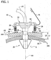
FIG. 1 is a front view showing a skin level device (SLD) of the invention in a gastrostomy tract of a patient; -
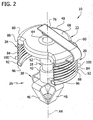
FIG. 2 is a top perspective of the SLD ofFIG. 1 ; -
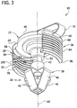
FIG. 3 is a bottom perspective of the SLD ofFIG. 2 ; -
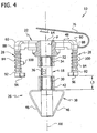
FIG. 4 is a front view of the SLD ofFIG. 2 , with portions broken away to illustrate details; -
FIG. 5 is a side view of the SLD ofFIG. 2 ; -
FIG. 6 is a top view of the SLD ofFIG. 2 ; -
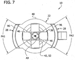
FIG. 7 is a bottom view of the SLD ofFIG. 2 ; and -
FIG. 8 is a front view of the SLD ofFIG. 1 after a reduction in abdominal wall thickness. - Corresponding reference characters indicate corresponding parts throughout the drawings.
- Referring to
FIG. 1 , an enteral feeding apparatus according to this invention is designated by thereference 10. (This apparatus is hereinafter referred to as a skin level device, or SLD.) The SLD 10 is fitted to a gastrostomy tract GT of a patient for delivering liquid nutrition to the stomach cavity S of the patient. Openings surgically formed in the abdominal wall AW and stomach wall SW of the patient are stitched together to form the gastrostomy tract GT. In general, theSLD 10 comprises atube 18, anexternal bolster 22 and aninternal bolster 26 which are adapted to be used as shown inFig. 1 . The SLD also includes a force-generating device which is operable when theinternal bolster 26 is positioned against a stomach wall surface SS to exert a force in an axial direction with respect to thetube 18 tending to hold theinternal bolster 26 in pressure contact with the stomach wall SW. As will described in detail later, the force-generating device has a length in the axial direction which varies automatically in response to a change in the length of the gastrostomy tract GT to maintain theinternal bolster 26 in pressure contact with the stomach wall SW without manual adjustment of theSLD 10. - As shown in
FIGS. 1 and4 , thetube 18 of theSLD 10 is disposed in the gastrostomy tract GT. Theinternal bolster 26 is attached to afirst end 30 of thetube 18 and is disposed inside the stomach cavity S. Theexternal bolster 22 is attached to asecond end 34 of thetube 18 and is disposed outside the patient on the abdominal wall surface AS. Thetube 18 has a generally cylindrical wall that defines alumen 36 having a longitudinal axis AX. Desirably, thetube 18 has a length and an outer diameter that is at least equal to a length and diameter of the gastrostomy tract GT. Variations of the tube design (e.g., variations in thickness of the cylindrical wall, the shape of the tube, etc.) are within the scope of the invention. - Referring to
FIGS. 2-5 , theinternal bolster 26 comprises a deformable retention structure 38 (best illustrated inFIGS. 4 and5 ) and atubular end section 42 connecting thedeformable retention structure 38 to thefirst end 30 of the tube. Theretention structure 38 comprises multiple retainingmembers 46. The retainingmembers 46 are movable from a contracted configuration (not shown) in which thestructure 38 has a generally uniform radial cross-section comparable to the diameter of thetubular end section 42 for permitting passage of theinternal bolster 26 through the gastrostomy tract GT, to an expanded configuration (as shown) in which thestructure 38 is wider at its end adjacent the stomach wall SW for contact with the stomach wall surface SS to retain theinternal bolster 26 inside the stomach cavity S. Other designs of theinternal bolster 26 for enabling insertion and anchoring of theSLD 10 are within the scope of the invention. - As illustrated in
FIG. 1-6 , theexternal bolster 22 has a generallycircular body 48 centered on the axis AX of thetube 18 and atubular end section 52 connecting thebody 48 to thesecond end 34 of the tube. Twoarms 60 extend laterally out from the body at opposite sides of thebody 48. As viewed from above (Fig. 6 ), thearms 60 have curved outer ends which define arcs of angular measure A1, A2 centered on axis AX. By way of example but not limitation, angles A1 and A2 may be about 60°. Other values are within the scope of the invention. An opening 64 (FIG. 4 ) extends through thebody 48 and communicates with thetubular end section 52. Desirably, theopening 64 is concentric with the axis AX and is sized for receiving either a feeding tube or a feeding tube connector, both generally designated by reference FT inFIG 1 . Aclosure 76 is tethered to one of thelateral arms 60 for closing theopening 64 between feeding sessions. Theclosure 76 may be connected to the external bolster 22 in other ways. As best illustrated inFIGS. 1 and4 , theopening 64 and thetubular end sections lumen 36 of thetube 18 and centered on axis AX to form a passage P for delivering nutrition to the patient from the feeding tube FT. A one way valve (not shown) may be formed anywhere in the passage P to prevent backflow of the liquid nutrients and/or gastric content. - Desirably, the ends 34, 30 of the
tube 18 are sealed within thetubular end sections tube 18 are within the scope of the invention. - Referring to
FIGS. 1-5 , the force-generating device is attached to the external bolster 22. The device is a spring device that, in the illustrated embodiment, includes a pair of spring members (each designated 28) extending from thelateral arms 60 of the external bolster 22 in a direction generally parallel to the axis AX towards the internal bolster 26. Eachspring member 28 includes aspring portion 84 that is axially expansible and contractible. Thespring member 28 has a first (upper) end 88 that attaches thespring portion 84 to a respectivelateral arm 60 and a second (lower)end 92. The connection of thespring portion 84 to thearm 60 is illustrated as an integral (one-piece) connection, but other connections are within the scope of the invention. Eachspring member 28 has afoot portion 96 connected to itslower end 92. Thefoot portion 96 provides an enlarged force-spreading surface for contacting and reacting against the abdominal wall surface AS, thereby improving stability and preventing patient discomfort. - In the illustrated embodiment of
FIGS. 3-7 , thespring portion 84 of eachspring member 28 comprises a plurality of elastic corrugations orpleats 100 which, like the coils of a spring, are resiliently expansible and contractible in an axial direction to produce a force. As best seen inFIGS. 3 and7 , thepleats 100 extend along arcs having inner and outer radii R1, R2 centered on the axis AX. Desirably, the arcs define pleat angles PA1, PA2 that are similar to respective angles A1, A2 of thelateral arms 60. Other values of the radii R1, R2 and pleat angles PA1, PA2 are within the scope of the invention. Other symmetric positions of thespring members 28 about axis AX on the external bolster 22 are within the scope of the invention. Any number ofspring members 28, including a single annular spring member, can be used. Desirably, in embodiments where more than one spring member is used, the spring members act independent of one another, that is, they can expand and contract independent of one another to accommodate local variations in stomach wall SW and/or abdominal wall AW thickness. - Returning to
FIG. 1 , when the various components of the enteral feeding apparatus are positioned as illustrated, thefoot portions 96 of thespring members 28 are against the abdominal wall surface AS and thespring portions 84 of thespring members 28 are resiliently contracted to produce an axial force along the axis AX, thereby imparting automatic adjustability to theSLD 10. That is, as the length L1 of the gastrostomy tract GT changes, the length of thespring portions 84 will also change while still providing the force necessary to hold the internal bolster 26 in pressure contact against the stomach wall surface SS. Thespring members 28 also serve to distance thebody 48 of the external bolster 22 from the abdominal wall surface AS. This feature reduces the amount of bolster area in contact with the skin and helps to prevent abrasion or chaffing. - Again referring to
FIG. 1 , a method of using theSLD 10 will now be described. Theretention structure 38 of theSLD 10 is moved to its contracted position (not shown) and inserted through the gastrostomy tract GT to a position inside the stomach. After entering the stomach, theretention structure 38 resiliently moves to its expanded condition, as shown inFIG. 1 , for engagement with the stomach wall SW to resist withdrawal under normal operating conditions. With theretention structure 38 positioned as shown, thetube 18 is disposed substantially in the tract GT, and the external bolster 22 is disposed substantially outside the tract GT on the abdominal wall surface AS. A feeding tube FT is connected to theopening 64 to supply nutrition to the patient. - With the components positioned as shown in
FIG. 1 , thespring members 28 are in a contracted condition and exert a force against the abdominal wall surface AS to hold the internal bolster 26 in pressure contact with the stomach wall surface SS. Eachspring member 28 of the pair ofspring members 28 automatically varies in length independent of the other spring member (as described earlier) and in response to changes in the tract length L1 to maintain the internal bolster 26 in pressure contact without manual intervention.FIGS. 1 and8 illustrate this automatic adjustability feature.FIG. 1 illustrates theSLD 10 when installed immediately after the tract GT is surgically created. The area surrounding the tract GT is generally inflamed and swollen, which causes the tract GT to have an increased length L1. Thespring members 28 contract to a greater extent to accommodate this increased length L1. InFIG. 8 , the surgery-induced inflammation and swelling of the abdominal wall AW has subsided, and the tract GT has a reduced length L2. As illustrated, the length of thespring members 28 has increased to accommodate this decrease in length (i.e., L1 - L2) of the tract GT. However, thespring members 28 remain contracted to exert the force necessary to maintain the internal bolster 22 in pressure contact with the surface SS. The adjustment is automatic. That is, no manual adjustment or replacement of theSLD 10 is needed. The same automatic adjustment will occur in the event the length of the tract GT changes due to weight gains or losses by the patient, or due to other changes. - The
SLD 10 may be part of a gastrostomy kit that also includes placement obturators, bolus feeding sets, continuous feeding sets, and other insertion/removal devices. - The
tube 18 and bolsters 22, 26 are formed of generally biocompatible, non-reactive and non-abrasive materials. Thetube 18 is preferably rigid, although this is not essential. Further, the retainingmembers 46 of the internal bolster 26 may be formed of any flexible material, such as silicone or polyurethane. Thespring members 28 may be formed of a suitable, elastically deformable material (e.g., PET) that is responsive to forces generated on theSLD 10 during physiological or other changes as described above. Other combination of materials can be used to form various components of theSLD 10 within the scope of the invention. - Having described the invention in detail, it will be apparent that modifications and variations are possible without departing from the scope of the invention defined in the appended claims. For example, in the illustrated embodiment, the force-generating device is a pair of
spring members 28 formed on opposite sides of the external bolster 22. However, any number of spring members can be used. For example, a single spring member may be formed near the periphery of the external bolster 22 circumscribing thetubular end section 52. That is, the pleat angle PA1 of the single spring member is 360°. In other embodiments, the tubular end sections42, 52 may have outer diameters sized to fit inside thetube 18. It is also possible for theentire SLD 10 to be integrally formed. Desirably, various components of theSLD 10 are sized such that the axial distance L3 (FIG. 4 ) between thefoot portions 96 and the upper end of thedeformable retention structure 38 is between 0.1 and 0.25 inches when thespring member 28 is in a fully expanded (relaxed) condition. - In view of the above, it will be seen that the several objects of the invention are achieved and other advantageous results attained. A patient that requires direct gastric feeding can use an
SLD 10 of this invention without concern about replacement or adjustment due to weight fluctuations, inflammation, etc. TheSLD 10 is economical to manufacture and further reduces equipment costs (no shims or replacements are required) and personnel costs (no periodic, manual intervention by health providers is needed).
Claims (10)
- Gastrostomy feeding apparatus (10) for providing enteral nutrition to a patient via a gastrostomy tract (GT) formed in the patient, said apparatus comprising:- a tube (18) defining a feeding lumen (36) having an axis (AX), said tube having first and second opposite ends (30, 34) and being adapted to be positioned in said gastrostomy tract (GT) for delivering enteral nutrition to the patient;- an internal bolster (26) connected to the tube (18) generally adjacent the first end (30) of the tube, said internal bolster being adapted to be positioned inside the stomach (S) of the patient;- an external bolster (22) connected to the tube (18) generally adjacent the second end (34) of the tube, said external bolster being adapted to be disposed outside the patient; and
characterized by a force-generating device comprising a pair of spring members (28) connected to said external bolster (22) adjacent a periphery of the bolster and generally on opposite sides of the axis (AX), each spring member having a first end (88) connected to the external bolster and an opposite second end (92) adapted to react against the patient for exerting said force, wherein each spring member comprises an axially expansible and contractible spring portion (84), and a foot portion (96) connected to said spring portion at said second end (92) of the spring member (28) for contact with the patient, each spring member being operable when the internal bolster (26) is positioned against a wall (SW) of the stomach (S) to exert a force in an axial direction with respect to the tube (18) tending to hold the internal bolster in pressure contact with the stomach wall, each spring member having a length in said axial direction which varies automatically in response to a change in the length of the gastrostomy tract to maintain said pressure contact without manual adjustment of the apparatus (10). - The apparatus of claim 1, wherein the internal and external bolsters (26, 22) have openings (64) therein aligned with said feeding lumen (36) to define a passage (P) for receiving a feeding tube (FT) for supplying nutrition to the patient.
- The apparatus of claim 2, further comprising a closure (76) tethered to the external bolster (22) for closing the opening (64) in the external bolster.
- The apparatus of claim 1, wherein the internal bolster (26) is spaced from the second end (92) of each spring member (28) by an axial distance ranging from 2.5 mm to 6.4 mm (0.10 inch to 0.25 inch) when the spring member is in a fully extended, relaxed condition.
- The apparatus of claim 1, wherein said spring portion (84) comprises a plurality of elastic pleats (100) extending along arcs centered on said axis.
- The apparatus of claim 5, wherein the internal bolster (26) is spaced from the second end (92) of each spring member (28) by an axial distance ranging from 2.5 mm to 6.4 mm (0.10 inch to 0.25 inch) when the spring member is in a fully extended, relaxed condition.
- The apparatus of any one of claims 5 or 6, wherein each spring member (28) of the pair of spring members expands and contracts independent of the other spring member of the pair of spring members.
- The apparatus of any one of claims 1-7, wherein the internal bolster (26) comprises a retention structure (38) contractible in a radial direction to permit insertion through the gastrostomy tract (GT) and expansible in a radial direction to resist withdrawal from the gastrostomy tract.
- The apparatus of any one of claims 1-8, wherein the internal bolster (26) comprises a first end section (42) connected to the first end (30) of the tube (18) and the external bolster (22) comprises a second end section (52) connected to the second end (34) of the tube, said first and second end sections having a first outside diameter and the tube (18) having a second outside diameter less than said first outside diameter.
- The apparatus of any one of claims 1-9, in combination with one or more of the following: one or more placement obturators, one or more bolus feeding sets, one or more continuous feeding sets, and one or more insertion/removal devices.
Applications Claiming Priority (1)
| Application Number | Priority Date | Filing Date | Title |
|---|---|---|---|
| US12/478,334 US8951232B2 (en) | 2009-06-04 | 2009-06-04 | Gastrostomy feeding apparatus and method |
Publications (3)
| Publication Number | Publication Date |
|---|---|
| EP2258334A2 EP2258334A2 (en) | 2010-12-08 |
| EP2258334A3 EP2258334A3 (en) | 2012-07-25 |
| EP2258334B1 true EP2258334B1 (en) | 2016-10-12 |
Family
ID=42651247
Family Applications (1)
| Application Number | Title | Priority Date | Filing Date |
|---|---|---|---|
| EP10005485.7A Not-in-force EP2258334B1 (en) | 2009-06-04 | 2010-05-27 | Gastrostomy feeding apparatus and method |
Country Status (4)
| Country | Link |
|---|---|
| US (1) | US8951232B2 (en) |
| EP (1) | EP2258334B1 (en) |
| CN (1) | CN101905058A (en) |
| CA (1) | CA2705177C (en) |
Families Citing this family (19)
| Publication number | Priority date | Publication date | Assignee | Title |
|---|---|---|---|---|
| US8858533B2 (en) | 2004-06-29 | 2014-10-14 | C. R. Bard, Inc. | Methods and systems for providing fluid communication with a gastrostomy tube |
| JP5184512B2 (en) | 2006-04-21 | 2013-04-17 | シー・アール・バード・インコーポレーテッド | Supply device, bolster apparatus, and method for producing the same |
| US8715244B2 (en) | 2009-07-07 | 2014-05-06 | C. R. Bard, Inc. | Extensible internal bolster for a medical device |
| JP2013066642A (en) * | 2011-09-26 | 2013-04-18 | Nihon Covidien Kk | Button type in-vitro body fixing instrument, and fistula catheter including the dame |
| US10695270B2 (en) | 2013-06-20 | 2020-06-30 | Hadasit Medical Research Services And Development Ltd. | Devices and methods for percutaneous endoscopic gastrostomy and other ostomy procedures |
| CN104069581B (en) * | 2014-07-21 | 2016-03-02 | 林新颖 | Intelligence automatic type War injury pleural/abdominal cavity drainage tube |
| US11426302B2 (en) | 2014-11-03 | 2022-08-30 | Fistula Solution Corporation | Containment devices for treatment of intestinal fistulas and complex wounds |
| US10702304B2 (en) | 2014-12-23 | 2020-07-07 | Fidmi Medical Ltd. | Devices and methods for ports to living tissue and/or lumens and related procedures |
| WO2016103268A1 (en) * | 2014-12-23 | 2016-06-30 | Fidmi Medical Ltd. | Devices and methods for percutaneous endoscopic gastronomy and other ostomy procedures |
| JP7176956B2 (en) | 2015-12-23 | 2022-11-22 | フィドミ メディカル リミテッド | Devices and methods for ports to body tissue and/or lumens, and related procedures |
| BE1024992B1 (en) * | 2017-02-20 | 2018-09-18 | Andocor Nv | ACCESS PROVIDING DEVICE |
| CA3123388A1 (en) | 2018-06-29 | 2020-01-02 | Generica Medical International, Inc. | Enteral feeding systems and methods |
| WO2020019090A1 (en) * | 2018-07-24 | 2020-01-30 | Pontificia Universidad Catolica De Chile | Simplified device for mounting a percutaneous endoscopic gastrotomy (peg) tube, which is installed outside the abdominal wall of a patient and which facilitates the connection thereof with an enteral feeding tube |
| US11207097B2 (en) | 2019-02-13 | 2021-12-28 | Andrew Thomas Obst | Fluid management device for medical tubes and drainage incisions |
| US11523932B2 (en) | 2019-06-26 | 2022-12-13 | Andrew Thomas Obst | Enteric fistula, rectovaginal fistula, and ostomy effluent containment system, and devices and methods thereof |
| WO2024036147A2 (en) | 2022-08-12 | 2024-02-15 | Luminoah, Inc. | Wearable fluid delivery system |
| USD1029235S1 (en) | 2022-08-12 | 2024-05-28 | Luminoah, Inc. | Fluid delivery system |
| USD1033628S1 (en) | 2022-08-12 | 2024-07-02 | Luminoah, Inc. | Fluid delivery module |
| USD1029236S1 (en) | 2022-08-12 | 2024-05-28 | Luminoah, Inc. | Fluid pouch assembly |
Family Cites Families (34)
| Publication number | Priority date | Publication date | Assignee | Title |
|---|---|---|---|---|
| US4596560A (en) | 1983-05-18 | 1986-06-24 | Mary Simpson | Gastronomy tube protector |
| US4699616A (en) * | 1986-06-13 | 1987-10-13 | Hollister Incorporated | Catheter retention device and method |
| US4738661A (en) | 1986-09-18 | 1988-04-19 | Marut Marie R | Gastrostomy belt |
| US4850953A (en) | 1987-07-27 | 1989-07-25 | Habley Medical Technology Corporation | Gastrostomy valve |
| US4832724A (en) | 1988-02-26 | 1989-05-23 | Corning Glass Works | Method of making colored photochromic glasses |
| US4944732A (en) | 1988-08-15 | 1990-07-31 | Sandoz Nutrition Corporation | Gastrostomy feeding port |
| US5092850A (en) | 1990-11-29 | 1992-03-03 | Buma Shelley J | Catheter with adjustable external locking bolster |
| US5205803A (en) * | 1992-04-06 | 1993-04-27 | Zemitis Martin S | Elastic cord apparatus |
| US5637097A (en) | 1992-04-15 | 1997-06-10 | Yoon; Inbae | Penetrating instrument having an expandable anchoring portion |
| US5484420A (en) | 1992-07-09 | 1996-01-16 | Wilson-Cook Medical Inc. | Retention bolsters for percutaneous catheters |
| US5273529A (en) * | 1992-12-04 | 1993-12-28 | Olajire Idowu | Gastrostomy tube with expandable insertion tip |
| US5413565A (en) | 1993-01-15 | 1995-05-09 | Sandoz Nutrition Ltd. | Gastrostomy feeding port with elastic adjustable tip |
| US5514133A (en) | 1994-08-26 | 1996-05-07 | Golub; Robert | Access device for endoscopic surgery |
| US5601537A (en) | 1995-06-05 | 1997-02-11 | Frassica; James J. | Catheter system |
| ES2236435T3 (en) | 1996-01-11 | 2005-07-16 | C.R. Bard Inc. | RETENTION HEAD FOR TUBE ASSEMBLY TO ACCESS THE BODY. |
| US5727555A (en) | 1996-06-18 | 1998-03-17 | Cook Incorporated | Indwelling catheter |
| US6546280B2 (en) | 1996-06-18 | 2003-04-08 | Cook Incorporated | Indwelling catheter |
| US6030361A (en) * | 1999-01-25 | 2000-02-29 | Miyashiro; Augusto M. | Gastrostomy apparatus |
| US6045536A (en) | 1999-02-24 | 2000-04-04 | Sherwood Services, A.G. | Securing device for a low profile gastrostomy tube |
| US6231549B1 (en) | 1999-08-17 | 2001-05-15 | Sherwood Services, Ag | Shim device for enteral feeding system |
| US6503245B2 (en) * | 2000-10-11 | 2003-01-07 | Medcanica, Inc. | Method of performing port off-pump beating heart coronary artery bypass surgery |
| JP4239163B2 (en) | 2003-01-08 | 2009-03-18 | 日本シャーウッド株式会社 | Gastrostomy tube |
| JP2004215804A (en) | 2003-01-14 | 2004-08-05 | Nippon Sherwood Medical Industries Ltd | Gastrostomy tube |
| JP2004275624A (en) | 2003-03-19 | 2004-10-07 | Nippon Sherwood Medical Industries Ltd | Gastrostomy tube |
| WO2004096115A1 (en) | 2003-04-28 | 2004-11-11 | Sumitomo Bakelite Company Limited | Catheter kit for burrow |
| JP4588356B2 (en) * | 2004-04-30 | 2010-12-01 | 日本シャーウッド株式会社 | Gastrostomy tube extender |
| JP4623548B2 (en) * | 2004-04-30 | 2011-02-02 | 日本シャーウッド株式会社 | Gastrostomy tube extender |
| US7582072B2 (en) * | 2004-09-09 | 2009-09-01 | Kimberly-Clark Worldwide, Inc. | Artificial stoma and method of use |
| US7410477B2 (en) | 2004-12-21 | 2008-08-12 | Gomez Matthew A | Supra pubic catheter |
| US7780650B2 (en) | 2005-05-04 | 2010-08-24 | Spirus Medical, Inc. | Rotate-to-advance catheterization system |
| EP1954339B1 (en) | 2005-11-30 | 2012-08-29 | Cook Medical Technologies LLC | Short wire peg and peg-j tube |
| US7883195B2 (en) | 2006-11-21 | 2011-02-08 | Xerox Corporation | Solid ink stick features for printer ink transport and method |
| JP5017721B2 (en) | 2007-10-10 | 2012-09-05 | 株式会社トップ | Button type gastrostomy tube |
| JP5414201B2 (en) | 2008-05-14 | 2014-02-12 | 日本コヴィディエン株式会社 | Fistula catheter and fistula catheter set |
-
2009
- 2009-06-04 US US12/478,334 patent/US8951232B2/en active Active
-
2010
- 2010-05-26 CA CA2705177A patent/CA2705177C/en active Active
- 2010-05-27 EP EP10005485.7A patent/EP2258334B1/en not_active Not-in-force
- 2010-06-04 CN CN2010101984423A patent/CN101905058A/en active Pending
Also Published As
| Publication number | Publication date |
|---|---|
| US20100312192A1 (en) | 2010-12-09 |
| EP2258334A3 (en) | 2012-07-25 |
| CA2705177A1 (en) | 2010-12-04 |
| CN101905058A (en) | 2010-12-08 |
| US8951232B2 (en) | 2015-02-10 |
| EP2258334A2 (en) | 2010-12-08 |
| CA2705177C (en) | 2014-12-16 |
Similar Documents
| Publication | Publication Date | Title |
|---|---|---|
| CA2705177C (en) | Gastrostomy feeding apparatus and method | |
| US7582072B2 (en) | Artificial stoma and method of use | |
| CA2442202C (en) | Low profile adaptor for use with a medical catheter | |
| EP1140272B1 (en) | Gastric balloon catheter with improved balloon orientation | |
| EP2969861B1 (en) | Fluid and nutrition delivery device and method of use | |
| US9039658B2 (en) | Medical catheter assembly including a balloon bolster | |
| US20080082081A1 (en) | Bolster assembly | |
| US20050038381A1 (en) | Catheter having a balloon member recessedly attached thereto | |
| EP1433494B1 (en) | Esophagus stoma button | |
| US7628775B2 (en) | Safety Y-port adaptor and medical catheter assembly including the same | |
| JP2004516076A (en) | Improved sealing valve assembly for medical supplies | |
| JP5907746B2 (en) | Low profile GJ feeding device | |
| CN106821765B (en) | Gastrostomy tube and fixing pad for gastrostomy tube | |
| JP4119904B2 (en) | Medical catheter fixture | |
| GB2552924A (en) | Feeding tube | |
| US20240299257A1 (en) | Stabilization devices for use with low-profile feeding devices and related methods of using the same | |
| EP2484402A2 (en) | A venflon component | |
| JP2016049245A (en) | Trans-gastrostomal jejunal tube | |
| US20250241828A1 (en) | System, apparatus, and method for relieving abdominal distention | |
| EP2666455B1 (en) | Low profile gastrostomy tubes | |
| JP2023523951A (en) | Polyurethane connective scaffold for feeding tube device | |
| KR20190040966A (en) | Nutrition Supply |
Legal Events
| Date | Code | Title | Description |
|---|---|---|---|
| PUAI | Public reference made under article 153(3) epc to a published international application that has entered the european phase |
Free format text: ORIGINAL CODE: 0009012 |
|
| AK | Designated contracting states |
Kind code of ref document: A2 Designated state(s): AL AT BE BG CH CY CZ DE DK EE ES FI FR GB GR HR HU IE IS IT LI LT LU LV MC MK MT NL NO PL PT RO SE SI SK SM TR |
|
| AX | Request for extension of the european patent |
Extension state: BA ME RS |
|
| PUAL | Search report despatched |
Free format text: ORIGINAL CODE: 0009013 |
|
| AK | Designated contracting states |
Kind code of ref document: A3 Designated state(s): AL AT BE BG CH CY CZ DE DK EE ES FI FR GB GR HR HU IE IS IT LI LT LU LV MC MK MT NL NO PL PT RO SE SI SK SM TR |
|
| AX | Request for extension of the european patent |
Extension state: BA ME RS |
|
| RIC1 | Information provided on ipc code assigned before grant |
Ipc: A61J 15/00 20060101AFI20120618BHEP Ipc: A61M 39/02 20060101ALN20120618BHEP |
|
| 17P | Request for examination filed |
Effective date: 20120903 |
|
| RAP1 | Party data changed (applicant data changed or rights of an application transferred) |
Owner name: COVIDIEN LP |
|
| 17Q | First examination report despatched |
Effective date: 20150623 |
|
| RIC1 | Information provided on ipc code assigned before grant |
Ipc: A61M 39/02 20060101ALN20160314BHEP Ipc: A61J 15/00 20060101AFI20160314BHEP |
|
| GRAP | Despatch of communication of intention to grant a patent |
Free format text: ORIGINAL CODE: EPIDOSNIGR1 |
|
| INTG | Intention to grant announced |
Effective date: 20160502 |
|
| GRAS | Grant fee paid |
Free format text: ORIGINAL CODE: EPIDOSNIGR3 |
|
| GRAA | (expected) grant |
Free format text: ORIGINAL CODE: 0009210 |
|
| AK | Designated contracting states |
Kind code of ref document: B1 Designated state(s): AL AT BE BG CH CY CZ DE DK EE ES FI FR GB GR HR HU IE IS IT LI LT LU LV MC MK MT NL NO PL PT RO SE SI SK SM TR |
|
| REG | Reference to a national code |
Ref country code: GB Ref legal event code: FG4D |
|
| REG | Reference to a national code |
Ref country code: CH Ref legal event code: EP |
|
| REG | Reference to a national code |
Ref country code: AT Ref legal event code: REF Ref document number: 835811 Country of ref document: AT Kind code of ref document: T Effective date: 20161015 |
|
| REG | Reference to a national code |
Ref country code: IE Ref legal event code: FG4D |
|
| REG | Reference to a national code |
Ref country code: DE Ref legal event code: R096 Ref document number: 602010037069 Country of ref document: DE |
|
| REG | Reference to a national code |
Ref country code: LT Ref legal event code: MG4D |
|
| REG | Reference to a national code |
Ref country code: NL Ref legal event code: MP Effective date: 20161012 |
|
| PG25 | Lapsed in a contracting state [announced via postgrant information from national office to epo] |
Ref country code: LV Free format text: LAPSE BECAUSE OF FAILURE TO SUBMIT A TRANSLATION OF THE DESCRIPTION OR TO PAY THE FEE WITHIN THE PRESCRIBED TIME-LIMIT Effective date: 20161012 |
|
| REG | Reference to a national code |
Ref country code: AT Ref legal event code: MK05 Ref document number: 835811 Country of ref document: AT Kind code of ref document: T Effective date: 20161012 |
|
| REG | Reference to a national code |
Ref country code: FR Ref legal event code: PLFP Year of fee payment: 8 |
|
| PG25 | Lapsed in a contracting state [announced via postgrant information from national office to epo] |
Ref country code: SE Free format text: LAPSE BECAUSE OF FAILURE TO SUBMIT A TRANSLATION OF THE DESCRIPTION OR TO PAY THE FEE WITHIN THE PRESCRIBED TIME-LIMIT Effective date: 20161012 Ref country code: GR Free format text: LAPSE BECAUSE OF FAILURE TO SUBMIT A TRANSLATION OF THE DESCRIPTION OR TO PAY THE FEE WITHIN THE PRESCRIBED TIME-LIMIT Effective date: 20170113 Ref country code: NO Free format text: LAPSE BECAUSE OF FAILURE TO SUBMIT A TRANSLATION OF THE DESCRIPTION OR TO PAY THE FEE WITHIN THE PRESCRIBED TIME-LIMIT Effective date: 20170112 Ref country code: LT Free format text: LAPSE BECAUSE OF FAILURE TO SUBMIT A TRANSLATION OF THE DESCRIPTION OR TO PAY THE FEE WITHIN THE PRESCRIBED TIME-LIMIT Effective date: 20161012 |
|
| PG25 | Lapsed in a contracting state [announced via postgrant information from national office to epo] |
Ref country code: IS Free format text: LAPSE BECAUSE OF FAILURE TO SUBMIT A TRANSLATION OF THE DESCRIPTION OR TO PAY THE FEE WITHIN THE PRESCRIBED TIME-LIMIT Effective date: 20170212 Ref country code: BE Free format text: LAPSE BECAUSE OF FAILURE TO SUBMIT A TRANSLATION OF THE DESCRIPTION OR TO PAY THE FEE WITHIN THE PRESCRIBED TIME-LIMIT Effective date: 20161012 Ref country code: PL Free format text: LAPSE BECAUSE OF FAILURE TO SUBMIT A TRANSLATION OF THE DESCRIPTION OR TO PAY THE FEE WITHIN THE PRESCRIBED TIME-LIMIT Effective date: 20161012 Ref country code: FI Free format text: LAPSE BECAUSE OF FAILURE TO SUBMIT A TRANSLATION OF THE DESCRIPTION OR TO PAY THE FEE WITHIN THE PRESCRIBED TIME-LIMIT Effective date: 20161012 Ref country code: HR Free format text: LAPSE BECAUSE OF FAILURE TO SUBMIT A TRANSLATION OF THE DESCRIPTION OR TO PAY THE FEE WITHIN THE PRESCRIBED TIME-LIMIT Effective date: 20161012 Ref country code: ES Free format text: LAPSE BECAUSE OF FAILURE TO SUBMIT A TRANSLATION OF THE DESCRIPTION OR TO PAY THE FEE WITHIN THE PRESCRIBED TIME-LIMIT Effective date: 20161012 Ref country code: AT Free format text: LAPSE BECAUSE OF FAILURE TO SUBMIT A TRANSLATION OF THE DESCRIPTION OR TO PAY THE FEE WITHIN THE PRESCRIBED TIME-LIMIT Effective date: 20161012 Ref country code: PT Free format text: LAPSE BECAUSE OF FAILURE TO SUBMIT A TRANSLATION OF THE DESCRIPTION OR TO PAY THE FEE WITHIN THE PRESCRIBED TIME-LIMIT Effective date: 20170213 Ref country code: NL Free format text: LAPSE BECAUSE OF FAILURE TO SUBMIT A TRANSLATION OF THE DESCRIPTION OR TO PAY THE FEE WITHIN THE PRESCRIBED TIME-LIMIT Effective date: 20161012 |
|
| REG | Reference to a national code |
Ref country code: DE Ref legal event code: R097 Ref document number: 602010037069 Country of ref document: DE |
|
| PG25 | Lapsed in a contracting state [announced via postgrant information from national office to epo] |
Ref country code: DK Free format text: LAPSE BECAUSE OF FAILURE TO SUBMIT A TRANSLATION OF THE DESCRIPTION OR TO PAY THE FEE WITHIN THE PRESCRIBED TIME-LIMIT Effective date: 20161012 Ref country code: EE Free format text: LAPSE BECAUSE OF FAILURE TO SUBMIT A TRANSLATION OF THE DESCRIPTION OR TO PAY THE FEE WITHIN THE PRESCRIBED TIME-LIMIT Effective date: 20161012 Ref country code: SK Free format text: LAPSE BECAUSE OF FAILURE TO SUBMIT A TRANSLATION OF THE DESCRIPTION OR TO PAY THE FEE WITHIN THE PRESCRIBED TIME-LIMIT Effective date: 20161012 Ref country code: CZ Free format text: LAPSE BECAUSE OF FAILURE TO SUBMIT A TRANSLATION OF THE DESCRIPTION OR TO PAY THE FEE WITHIN THE PRESCRIBED TIME-LIMIT Effective date: 20161012 Ref country code: RO Free format text: LAPSE BECAUSE OF FAILURE TO SUBMIT A TRANSLATION OF THE DESCRIPTION OR TO PAY THE FEE WITHIN THE PRESCRIBED TIME-LIMIT Effective date: 20161012 |
|
| PLBE | No opposition filed within time limit |
Free format text: ORIGINAL CODE: 0009261 |
|
| STAA | Information on the status of an ep patent application or granted ep patent |
Free format text: STATUS: NO OPPOSITION FILED WITHIN TIME LIMIT |
|
| PG25 | Lapsed in a contracting state [announced via postgrant information from national office to epo] |
Ref country code: BG Free format text: LAPSE BECAUSE OF FAILURE TO SUBMIT A TRANSLATION OF THE DESCRIPTION OR TO PAY THE FEE WITHIN THE PRESCRIBED TIME-LIMIT Effective date: 20170112 Ref country code: LU Free format text: LAPSE BECAUSE OF NON-PAYMENT OF DUE FEES Effective date: 20170531 Ref country code: IT Free format text: LAPSE BECAUSE OF FAILURE TO SUBMIT A TRANSLATION OF THE DESCRIPTION OR TO PAY THE FEE WITHIN THE PRESCRIBED TIME-LIMIT Effective date: 20161012 Ref country code: SM Free format text: LAPSE BECAUSE OF FAILURE TO SUBMIT A TRANSLATION OF THE DESCRIPTION OR TO PAY THE FEE WITHIN THE PRESCRIBED TIME-LIMIT Effective date: 20161012 |
|
| 26N | No opposition filed |
Effective date: 20170713 |
|
| PG25 | Lapsed in a contracting state [announced via postgrant information from national office to epo] |
Ref country code: SI Free format text: LAPSE BECAUSE OF FAILURE TO SUBMIT A TRANSLATION OF THE DESCRIPTION OR TO PAY THE FEE WITHIN THE PRESCRIBED TIME-LIMIT Effective date: 20161012 |
|
| REG | Reference to a national code |
Ref country code: CH Ref legal event code: PL |
|
| PG25 | Lapsed in a contracting state [announced via postgrant information from national office to epo] |
Ref country code: MC Free format text: LAPSE BECAUSE OF FAILURE TO SUBMIT A TRANSLATION OF THE DESCRIPTION OR TO PAY THE FEE WITHIN THE PRESCRIBED TIME-LIMIT Effective date: 20161012 |
|
| REG | Reference to a national code |
Ref country code: IE Ref legal event code: MM4A |
|
| PG25 | Lapsed in a contracting state [announced via postgrant information from national office to epo] |
Ref country code: LI Free format text: LAPSE BECAUSE OF NON-PAYMENT OF DUE FEES Effective date: 20170531 Ref country code: CH Free format text: LAPSE BECAUSE OF NON-PAYMENT OF DUE FEES Effective date: 20170531 |
|
| REG | Reference to a national code |
Ref country code: GB Ref legal event code: 732E Free format text: REGISTERED BETWEEN 20180208 AND 20180214 |
|
| PG25 | Lapsed in a contracting state [announced via postgrant information from national office to epo] |
Ref country code: LU Free format text: LAPSE BECAUSE OF NON-PAYMENT OF DUE FEES Effective date: 20170527 |
|
| PG25 | Lapsed in a contracting state [announced via postgrant information from national office to epo] |
Ref country code: IE Free format text: LAPSE BECAUSE OF NON-PAYMENT OF DUE FEES Effective date: 20170527 |
|
| REG | Reference to a national code |
Ref country code: FR Ref legal event code: PLFP Year of fee payment: 9 |
|
| PG25 | Lapsed in a contracting state [announced via postgrant information from national office to epo] |
Ref country code: MT Free format text: LAPSE BECAUSE OF NON-PAYMENT OF DUE FEES Effective date: 20170527 |
|
| PG25 | Lapsed in a contracting state [announced via postgrant information from national office to epo] |
Ref country code: HU Free format text: LAPSE BECAUSE OF FAILURE TO SUBMIT A TRANSLATION OF THE DESCRIPTION OR TO PAY THE FEE WITHIN THE PRESCRIBED TIME-LIMIT; INVALID AB INITIO Effective date: 20100527 |
|
| PG25 | Lapsed in a contracting state [announced via postgrant information from national office to epo] |
Ref country code: CY Free format text: LAPSE BECAUSE OF NON-PAYMENT OF DUE FEES Effective date: 20161012 |
|
| PG25 | Lapsed in a contracting state [announced via postgrant information from national office to epo] |
Ref country code: MK Free format text: LAPSE BECAUSE OF FAILURE TO SUBMIT A TRANSLATION OF THE DESCRIPTION OR TO PAY THE FEE WITHIN THE PRESCRIBED TIME-LIMIT Effective date: 20161012 |
|
| PG25 | Lapsed in a contracting state [announced via postgrant information from national office to epo] |
Ref country code: TR Free format text: LAPSE BECAUSE OF FAILURE TO SUBMIT A TRANSLATION OF THE DESCRIPTION OR TO PAY THE FEE WITHIN THE PRESCRIBED TIME-LIMIT Effective date: 20161012 |
|
| PG25 | Lapsed in a contracting state [announced via postgrant information from national office to epo] |
Ref country code: AL Free format text: LAPSE BECAUSE OF FAILURE TO SUBMIT A TRANSLATION OF THE DESCRIPTION OR TO PAY THE FEE WITHIN THE PRESCRIBED TIME-LIMIT Effective date: 20161012 |
|
| PGFP | Annual fee paid to national office [announced via postgrant information from national office to epo] |
Ref country code: GB Payment date: 20240527 Year of fee payment: 15 |
|
| PGFP | Annual fee paid to national office [announced via postgrant information from national office to epo] |
Ref country code: DE Payment date: 20240530 Year of fee payment: 15 |
|
| PGFP | Annual fee paid to national office [announced via postgrant information from national office to epo] |
Ref country code: FR Payment date: 20240527 Year of fee payment: 15 |
|
| REG | Reference to a national code |
Ref country code: DE Ref legal event code: R119 Ref document number: 602010037069 Country of ref document: DE |
|
| GBPC | Gb: european patent ceased through non-payment of renewal fee |
Effective date: 20250527 |
|
| PG25 | Lapsed in a contracting state [announced via postgrant information from national office to epo] |
Ref country code: GB Free format text: LAPSE BECAUSE OF NON-PAYMENT OF DUE FEES Effective date: 20250527 |
|
| PG25 | Lapsed in a contracting state [announced via postgrant information from national office to epo] |
Ref country code: DE Free format text: LAPSE BECAUSE OF NON-PAYMENT OF DUE FEES Effective date: 20251202 |
|
| PG25 | Lapsed in a contracting state [announced via postgrant information from national office to epo] |
Ref country code: FR Free format text: LAPSE BECAUSE OF NON-PAYMENT OF DUE FEES Effective date: 20250531 |