EP2258323A1 - Applikationsvorrichtung für Stents mit funktional strukturierter Oberfläche - Google Patents
Applikationsvorrichtung für Stents mit funktional strukturierter Oberfläche Download PDFInfo
- Publication number
- EP2258323A1 EP2258323A1 EP10157040A EP10157040A EP2258323A1 EP 2258323 A1 EP2258323 A1 EP 2258323A1 EP 10157040 A EP10157040 A EP 10157040A EP 10157040 A EP10157040 A EP 10157040A EP 2258323 A1 EP2258323 A1 EP 2258323A1
- Authority
- EP
- European Patent Office
- Prior art keywords
- stent
- application device
- hair
- stents
- application
- Prior art date
- Legal status (The legal status is an assumption and is not a legal conclusion. Google has not performed a legal analysis and makes no representation as to the accuracy of the status listed.)
- Granted
Links
- 238000002513 implantation Methods 0.000 title description 2
- 238000005411 Van der Waals force Methods 0.000 claims abstract description 13
- 229920000642 polymer Polymers 0.000 claims abstract description 12
- 239000011248 coating agent Substances 0.000 claims abstract description 5
- 238000000576 coating method Methods 0.000 claims abstract description 5
- YCIMNLLNPGFGHC-UHFFFAOYSA-N catechol Chemical compound OC1=CC=CC=C1O YCIMNLLNPGFGHC-UHFFFAOYSA-N 0.000 claims description 10
- 238000002788 crimping Methods 0.000 claims description 10
- 208000031481 Pathologic Constriction Diseases 0.000 claims description 3
- 239000000463 material Substances 0.000 description 10
- 238000000034 method Methods 0.000 description 8
- 238000012360 testing method Methods 0.000 description 6
- 239000000956 alloy Substances 0.000 description 5
- 229910045601 alloy Inorganic materials 0.000 description 5
- 239000000203 mixture Substances 0.000 description 4
- 238000005260 corrosion Methods 0.000 description 3
- 230000007797 corrosion Effects 0.000 description 3
- 239000012530 fluid Substances 0.000 description 3
- XEEYBQQBJWHFJM-UHFFFAOYSA-N Iron Chemical compound [Fe] XEEYBQQBJWHFJM-UHFFFAOYSA-N 0.000 description 2
- WTDRDQBEARUVNC-UHFFFAOYSA-N L-Dopa Natural products OC(=O)C(N)CC1=CC=C(O)C(O)=C1 WTDRDQBEARUVNC-UHFFFAOYSA-N 0.000 description 2
- FAPWRFPIFSIZLT-UHFFFAOYSA-M Sodium chloride Chemical compound [Na+].[Cl-] FAPWRFPIFSIZLT-UHFFFAOYSA-M 0.000 description 2
- VYFYYTLLBUKUHU-UHFFFAOYSA-N dopamine Chemical compound NCCC1=CC=C(O)C(O)=C1 VYFYYTLLBUKUHU-UHFFFAOYSA-N 0.000 description 2
- 238000003780 insertion Methods 0.000 description 2
- 230000037431 insertion Effects 0.000 description 2
- NQIMONOHVBBZKE-UHFFFAOYSA-N n-[2-(3,4-dihydroxyphenyl)ethyl]-2-methylprop-2-enamide Chemical compound CC(=C)C(=O)NCCC1=CC=C(O)C(O)=C1 NQIMONOHVBBZKE-UHFFFAOYSA-N 0.000 description 2
- 230000002093 peripheral effect Effects 0.000 description 2
- 206010002329 Aneurysm Diseases 0.000 description 1
- WTDRDQBEARUVNC-LURJTMIESA-N L-DOPA Chemical compound OC(=O)[C@@H](N)CC1=CC=C(O)C(O)=C1 WTDRDQBEARUVNC-LURJTMIESA-N 0.000 description 1
- FYYHWMGAXLPEAU-UHFFFAOYSA-N Magnesium Chemical compound [Mg] FYYHWMGAXLPEAU-UHFFFAOYSA-N 0.000 description 1
- 229940024606 amino acid Drugs 0.000 description 1
- 150000001413 amino acids Chemical class 0.000 description 1
- 230000017531 blood circulation Effects 0.000 description 1
- 210000004204 blood vessel Anatomy 0.000 description 1
- 238000005266 casting Methods 0.000 description 1
- 230000015556 catabolic process Effects 0.000 description 1
- 150000003943 catecholamines Chemical class 0.000 description 1
- 210000004351 coronary vessel Anatomy 0.000 description 1
- 238000006731 degradation reaction Methods 0.000 description 1
- MHUWZNTUIIFHAS-CLFAGFIQSA-N dioleoyl phosphatidic acid Chemical compound CCCCCCCC\C=C/CCCCCCCC(=O)OCC(COP(O)(O)=O)OC(=O)CCCCCCC\C=C/CCCCCCCC MHUWZNTUIIFHAS-CLFAGFIQSA-N 0.000 description 1
- 229960003638 dopamine Drugs 0.000 description 1
- 230000000694 effects Effects 0.000 description 1
- 238000000609 electron-beam lithography Methods 0.000 description 1
- 238000005530 etching Methods 0.000 description 1
- 210000004209 hair Anatomy 0.000 description 1
- 230000000977 initiatory effect Effects 0.000 description 1
- 229910052742 iron Inorganic materials 0.000 description 1
- 229960004502 levodopa Drugs 0.000 description 1
- 238000001459 lithography Methods 0.000 description 1
- 229910052749 magnesium Inorganic materials 0.000 description 1
- 239000011777 magnesium Substances 0.000 description 1
- 210000000056 organ Anatomy 0.000 description 1
- 229920001690 polydopamine Polymers 0.000 description 1
- 239000011780 sodium chloride Substances 0.000 description 1
- 230000003319 supportive effect Effects 0.000 description 1
- 230000001225 therapeutic effect Effects 0.000 description 1
- WFKWXMTUELFFGS-UHFFFAOYSA-N tungsten Chemical compound [W] WFKWXMTUELFFGS-UHFFFAOYSA-N 0.000 description 1
- 229910052721 tungsten Inorganic materials 0.000 description 1
- 239000010937 tungsten Substances 0.000 description 1
- 230000002792 vascular Effects 0.000 description 1
- 208000019553 vascular disease Diseases 0.000 description 1
Images

Classifications
-
- A—HUMAN NECESSITIES
- A61—MEDICAL OR VETERINARY SCIENCE; HYGIENE
- A61F—FILTERS IMPLANTABLE INTO BLOOD VESSELS; PROSTHESES; DEVICES PROVIDING PATENCY TO, OR PREVENTING COLLAPSING OF, TUBULAR STRUCTURES OF THE BODY, e.g. STENTS; ORTHOPAEDIC, NURSING OR CONTRACEPTIVE DEVICES; FOMENTATION; TREATMENT OR PROTECTION OF EYES OR EARS; BANDAGES, DRESSINGS OR ABSORBENT PADS; FIRST-AID KITS
- A61F2/00—Filters implantable into blood vessels; Prostheses, i.e. artificial substitutes or replacements for parts of the body; Appliances for connecting them with the body; Devices providing patency to, or preventing collapsing of, tubular structures of the body, e.g. stents
- A61F2/95—Instruments specially adapted for placement or removal of stents or stent-grafts
- A61F2/958—Inflatable balloons for placing stents or stent-grafts
-
- A—HUMAN NECESSITIES
- A61—MEDICAL OR VETERINARY SCIENCE; HYGIENE
- A61F—FILTERS IMPLANTABLE INTO BLOOD VESSELS; PROSTHESES; DEVICES PROVIDING PATENCY TO, OR PREVENTING COLLAPSING OF, TUBULAR STRUCTURES OF THE BODY, e.g. STENTS; ORTHOPAEDIC, NURSING OR CONTRACEPTIVE DEVICES; FOMENTATION; TREATMENT OR PROTECTION OF EYES OR EARS; BANDAGES, DRESSINGS OR ABSORBENT PADS; FIRST-AID KITS
- A61F2/00—Filters implantable into blood vessels; Prostheses, i.e. artificial substitutes or replacements for parts of the body; Appliances for connecting them with the body; Devices providing patency to, or preventing collapsing of, tubular structures of the body, e.g. stents
- A61F2/95—Instruments specially adapted for placement or removal of stents or stent-grafts
- A61F2/958—Inflatable balloons for placing stents or stent-grafts
- A61F2002/9583—Means for holding the stent on the balloon, e.g. using protrusions, adhesives or an outer sleeve
-
- A—HUMAN NECESSITIES
- A61—MEDICAL OR VETERINARY SCIENCE; HYGIENE
- A61M—DEVICES FOR INTRODUCING MEDIA INTO, OR ONTO, THE BODY; DEVICES FOR TRANSDUCING BODY MEDIA OR FOR TAKING MEDIA FROM THE BODY; DEVICES FOR PRODUCING OR ENDING SLEEP OR STUPOR
- A61M25/00—Catheters; Hollow probes
- A61M25/10—Balloon catheters
-
- A—HUMAN NECESSITIES
- A61—MEDICAL OR VETERINARY SCIENCE; HYGIENE
- A61M—DEVICES FOR INTRODUCING MEDIA INTO, OR ONTO, THE BODY; DEVICES FOR TRANSDUCING BODY MEDIA OR FOR TAKING MEDIA FROM THE BODY; DEVICES FOR PRODUCING OR ENDING SLEEP OR STUPOR
- A61M25/00—Catheters; Hollow probes
- A61M25/10—Balloon catheters
- A61M25/104—Balloon catheters used for angioplasty
Definitions
- the present invention relates to the field of stent delivery devices.
- stents have the purpose to take on a supportive function in hollow organs of a patient.
- stents of conventional design have a tubular basic body with a filigree support structure of metallic struts, which is initially present in a compressed form for introduction into the body and is widened at the site of the application.
- One of the main areas of application of such stents is the permanent or temporary widening and keeping open of vascular constrictions, in particular constrictions (stenoses) of the coronary arteries.
- aneurysm stents are known which serve to support damaged vessel walls.
- Stents have a peripheral wall of sufficient bearing capacity to keep the stenosed vessel open to the desired extent, and a tubular body through which blood flow continues unimpeded.
- the peripheral wall is usually formed by a grid-like support structure, which allows to introduce the stent in a compressed state with a small outer diameter to be treated bottleneck of each vessel and there, for example, with the aid of an application device, such as a catheter to apply, that the vessel has the desired, enlarged inner diameter.
- Balloon catheters are usually used for the application of non-self-expandable stents.
- the stent is fixed on a surface of the non-dilated balloon usually by so-called "crimping".
- the balloon catheter loaded with the stent has been introduced into the vessel and the stent has arrived at the point at which it is to be applied, the balloon is dilated.
- the stent is widened and brought into contact with the vessel wall.
- the pressure in the balloon is reduced, the balloon returns to a non-dilated state and can be removed again while the applied stent remains in the vessel and keeps it open.
- Suitable balloon catheters for stent application are known and exemplified in DE 102 15 462 described.
- a self-expanding stent design can be used.
- Application devices for the application of self-expanding stents usually have no dilatable balloon for stent application.
- catheter devices are usually used, which have an inner tube and an outer tube, wherein the stent to be applied is first present crimped on a surface of the inner tube and is covered by an outer tube pushed over it.
- Self-expanding stents have in crimped form a radial force which presses the stent outer surface against the inner surface of the outer tube covering the stent.
- the catheter is inserted into the vessel until the stent comes to rest where it is to be applied.
- the outer tube is then withdrawn until the entire stent is exposed.
- a self-expandable stent must be so fixed on the inner tube that it does not slip during retraction of the outer tube during the application process.
- the stent When using a balloon catheter, the stent must be fixed on the non-dilated balloon surface. This is not always possible for all types of stents. Thus, e.g. drug-eluting stents, stents with a large StrutwandC or stents with large Strutbreite are often not sufficiently fixed by simple crimping.
- the object of the present invention is to reduce or prevent one or more disadvantages of the prior art.
- stent delivery devices are to be provided which require fewer additional stent fixation measures.
- the object is achieved by providing a stent delivery device having hair-like extensions on at least part of the outward-facing surface of the region of the device, which is provided for attaching or crimping the stent to be applied, the average diameter D being the average diameter Length L and the average center-to-center distance P of the hair-like projections to each other are selected such that a stent on the surface covered with hair-like projections is substantially fixable by van der Waals forces.
- one surface of the application device has a plurality of hair-like extensions.
- the gecko can run through a variety of sub-micrometer-sized hairs on his feet even smooth surfaces vertically or upside down.
- This effect is a combination of capillary forces and van der Waals forces.
- the van der Waals forces of such a surface structure are used to fix a crimped stent on a surface of the application device and to release it again only when required.
- This surface structuring makes it possible to dispense with measures for stent fixation, which follow a crimping.
- the stent By contact of said surface structure of the application device with an inner surface of the stent, the stent is fixed substantially by van der Waals forces on the application device.
- the sum of the van der Waals forces per hair-like extension together gives a sufficient holding force for the stent.
- the van der Waals forces between the inner surface of the stent and the hair-like projections are greatest when the force acts vertically on the contact surface of the hair-like projections, as in the case of introducing the stented balloon catheter into a vessel.
- any application device for stents can be used, provided that a surface of the stent to be applied is in contact with a surface of the application device prior to application.
- the application device comprises a catheter.
- the application device may comprise a dilatable balloon surface onto which a stent may be crimped, such as a balloon catheter, for example.
- a balloon catheter may be used having an inner shaft to which is attached a distal end of an expandable balloon which, in an unexpanded, deflated state, at least partially abuts an outer surface of the inner shaft.
- the invention relates to such catheters which can carry on the outside of the deflated balloon a stent which expands upon insertion into a vessel by inflation of the balloon with a fluid and is thus pressed at the intended location to a vessel wall.
- Balloon catheters of the intended type usually also have, in addition to an inner shaft and the balloon, an outer shaft which extends at least as far as a proximal end of the balloon and is connected to it in a fluid-tight manner. Between the inner and outer sheath of the catheter is usually provided in the longitudinal direction of the catheter from its proximal end to the interior of the balloon reaching fluid line, for example, results from the fact that the outer shaft has an inner diameter which is greater than an outer diameter of the inner shaft.
- a cavity enclosed by the inner shaft and extending in the longitudinal direction of the inner shaft is provided as a lumen.
- This lumen serves for example to receive a stylet or a guide wire.
- the catheter and guidewire are adapted to allow the guidewire to exit at the distal tip of the catheter and to be controlled from the proximal end.
- the guidewire is deflected, for example, by means of control means so that it is easy to insert into branching blood vessels.
- the balloon catheter can then be pushed along the guidewire.
- balloon catheters have at their distal end the already mentioned, expandable balloon.
- the balloon is compressed and fits tightly against the inner shaft of the catheter.
- By inflating the balloon with a fluid it can be expanded. This expansion of the balloon happens as soon as the balloon is guided to the intended position.
- the stent is plastically deformed so that it can permanently attach to a vessel wall.
- the application device according to the invention may alternatively be designed as a device for the application of self-expandable stents, for example have a surface for the application of self-expandable stents.
- Devices for the application of self-expandable stents are characterized in that no means for the active plastic deformation of a crimped stent are necessary.
- Catheters are preferably used which instead of a balloon have a region of an inner shaft onto which the self-expandable stent can be crimped for application.
- such a catheter has means which allow the crimped self-expandable stent to be prevented from self-expanding until the stent has been brought to the particular position and then allow initiation of self-expansion of the stent.
- This can be achieved, for example, by surrounding the self-expandable stent crimped on the inner tube with an outer tube which prevents the stent from self-expansion.
- This outer tube can be designed such that retraction of the outer tube relative to the inner tube is possible, so that a region of the inner tube can be released on which the self-expandable stent is present in a crimped state. If the outer tube is withdrawn sufficiently far enough, the stent can detach itself from the inner tube due to its radial force, expand independently and come into contact with the vessel wall.
- the application device has at least on a part of the outwardly facing surface of the region of the device hair-like extensions, which is provided for crimping the stent to be applied.
- Areas of the application device or parts thereof may be provided with hair-like extensions which are in contact with a surface of the stent to be applied prior to application.
- at least 20% of the surface to be covered by the stent to be applied has hair-like extensions, more preferably 30% to 100% of the surface covered by the stent to be applied has hair-like extensions.
- the hair-like projections have a shape that is based on the surface of the application device and rises above it.
- the hair-like extensions can have one or more side surfaces and optionally a surface which is remote from the surface of the application form and which can be brought into contact with a surface of the stent to be applied.
- the hair-like extensions are substantially cylindrical.
- the hair-like projections can basically be made of any material that can be connected to a surface of the application device that can be covered by the stent to be applied and that is sufficiently compatible for use inside a human body.
- the hair-like structures are preferably made of materials or material compositions that have strength and rigidity so that the hair-like extensions can protrude upright from the surface and do not collapse or kink in themselves.
- the hair-like extensions can in particular be made of the same material from which the surface of the application device which can be covered by a stent to be applied is produced. Suitable materials and polymers are known to the person skilled in the art.
- a surface with hair-like projections can be produced by different methods.
- negative forms can be produced by lithographic techniques such as electron beam lithography and laser lithography, or by etching techniques.
- the positive surface with hair-like extensions is then produced on the basis of the negative shape (see, for example, FIG AK Geim et al., Nature Mater. 2, 461-463 (2003 ) and Lee, BP Lee and PB Messersmith, Nature 448, 338-341 (2007 )).
- the average diameter D of the hair-like projections, the average length L of the hair-like projections, and the average center-to-center distance P of the hair-like projections to each other are parameters that influence the size of the achievable van der Waals forces.
- D can be determined by determining the diameters of all hair-like extensions for a selected area, adding them together and dividing the obtained sum by the number of measured hair-like extensions.
- L can be determined by determining the length of all hair-like extensions for a selected area, adding them together, and dividing the obtained sum by the number of measured hair-like extensions.
- P can be determined by determining, for a selected area, the distances of all hair-like extensions to the nearest hair-like extension, starting from a center of a first hair-like extension to the center of the nearest hair-like extension. The obtained distance values are added and the sum obtained is divided by the number of measured hair-like extensions.
- D, L and P are selected such that a given stent can be fixed on the surface of the application device covered with hair-like projections.
- the material properties of the material that was used to produce the hair-like projections also influences the achievable van der Waals forces, for example the density of the material surface.
- the required van der Waals forces to fix a particular stent according to the invention on the surface of the application device are not the same for each stent and must therefore be redetermined for each combination of stent and inventive application device.
- test surfaces can be provided which have hair-like extensions with different combinations of D, L and P. These test surfaces may then be brought into contact with surface portions of the desired stents or the inner surfaces of whole stents. Subsequently, the force necessary to remove the test surface from the stent surface is determined.
- D may be selected from a range of 0.05 to 5 microns, preferably 0.1 to 4 microns, more preferably from 0.2 to 1 micron.
- L may in particular be selected from a range of 0.1 to 20 .mu.m, preferably 0.1 to 5 .mu.m, more preferably from 0.15 to 2 microns.
- P may in particular be selected from a range of 0.1 to 5 microns, preferably from 0.5 to 3 microns.
- D and L are selected such that there is a ratio of D to L which is selected from a range of 0.5 to 2, preferably 0.75 to 1.5.
- P and D are selected to give a ratio of P to D selected from a range of 1 to 50, preferably 1.5 to 10.
- the application device may have hair-like extensions, wherein the hair-like extensions are coated with a polymer having catechol side groups.
- These polymers further increase the adhesiveness of hair-like processes.
- Suitable polymers as well as polymer compositions and methods of coating are disclosed in U.S. Pat WO 08/091386 disclosed.
- Such polymers may include catecholamines such as dopamine or the amino acid 3,4-dihydroxy-L-phenylalanine, also known as DOPA.
- a particularly preferred polymer is poly (dopamine methacrylamide (DMA) - co -methoxyethyl acrylate (MEA)).
- Preferred polymers have catechol side groups, with the catechol pendant groups accounting for at least 5 weight percent of the total polymer weight, more preferably from 10 weight percent to 70 weight percent.
- the coating of the hair-like projections with a polymer having catechol side groups may have a layer thickness of less than 100 nm, and the layer thickness is preferably selected from a range of 1 nm to 50 nm.
- the present invention also relates to an application device which additionally has an applicable stent, an administrable, drug-eluting stent or an administrable, biodegradable stent.
- the stent is so on the application device attached so that the stent is applied.
- the stent is attached or crimped on a surface of the application device provided for this purpose and provided with hair-like projections at least partially in the manner described above.
- Biodegradable stents are in particular understood to mean stents which have biocorrodible alloys of the elements magnesium, iron or tungsten for the main body of the stent. The alloys are to be chosen in their composition so that they are biocorrodible.
- biocorrodible materials are alloys in which degradation takes place in a physiological environment, which ultimately leads to the entire stent or the part of the stent formed from the material losing its mechanical integrity.
- artificial plasma as prescribed in EN ISO 10993-15: 2000 for biocorrosion studies (composition NaCl 6.8 g / l, CaCl 2 0.2 g / l, KCl 0 , 4 g / l, MgSO 4 0.1 g / l, NaHCO 3 2.2 g / l, Na 2 HPO 4 0.166 g / l, NaH 2 PO 4 0.026 g / l).
- a sample of the alloy to be examined is stored in a sealed sample container with a defined amount of the test medium at 37 ° C. At intervals - adjusted to the expected corrosion behavior - from a few hours to several months, the samples are taken and examined in a known manner for traces of corrosion.
- the artificial plasma according to EN ISO 10993-15: 2000 corresponds to a blood-like medium and thus represents a possibility to reproducibly reproduce a physiological environment within the meaning of the invention.
- the present invention also relates to a use of an application device according to the invention for the application of stents, self-expandable stents, drug-eluting stents and / or biodegradable stents, as well as for the treatment of stenoses.
- FIG. 1 Shown embodiment of the application device according to the invention is a balloon catheter 1.
- the balloon catheter 1 has a dilatable region 2.
- At least on a part of the outwardly facing surface 3 of the dilatable region 2 is a plurality of hair-like extensions 4.
- This outwardly facing surface 3 may be in contact with an inner surface of the stent after application or crimping of the stent to be applied to the application device serves to fix the stent on the application device.
- the hair-like projections 4 have a certain average diameter D, a certain average length L and a certain average center-to-center distance P.
- D, L and P are selected so that van der Waals forces between the hair-like projections 4 and an inner surface of a stent to be applied come about, which allow a fixation of the stent on the application device.
- the hair-like projections 4 each have a surface that can be contacted with an inner surface of a stent to be applied, exemplified by 5a to 5f.
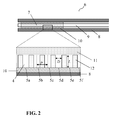
- FIG. 2 is shown as a further embodiment of the invention by way of example an application device 6 for the application of self-expandable stents.
- the device 6 has an inner tube 9, a retractable outer tube 8, and a region 7, which is provided for attaching or crimping the stent to be applied.
- the outer tube 8 is designed such that it can be retracted in relation to the inner tube, so that the area 7 can be exposed.
- the device 6 has a self-expanding stent 10, which in the area 7 between Inner tube 9 and outer tube 8 is fixed. At least on a part of the outwardly facing surface 11 of the region 7 is a plurality of hair-like extensions 4.
- This outwardly facing surface 11 is at least partially in contact with an inner surface of the stent 10 and serves to fix the stent 10 on the application device 6.
- the hair-like projections 4 have a certain average diameter D, a certain average length L and a certain average center-to-center distance P.
- D, L and P are selected so that van der Waals forces between the hair-like projections 4 and an inner surface of a stent 10 to be applied come about, which allow a fixation of the stent 10 on the application device 6.
- the hair-like projections 4 each have a surface that can be contacted with an inner surface of a stent 10 to be applied, exemplified by 5a to 5f. There is a lumen 12 between adjacent hair-like projections 4.
- the contact between stent 10 and hair-like extensions 4 of region 7 results in a fixation of the stent on the application device 6 as long as the stent is still covered by parts of the retractable outer tube 8. If the application device 6 is placed so that the stent 10 can be applied to the desired location, the outer tube 8 is withdrawn, the stent 10 is exposed, detached by independent radial forces of area 7 of the inner tube 9 and expands independently until he has, for example, attached to a vessel wall and remains there. After the application, the device 6, now without the applied stent 10, be removed again.
Landscapes
- Health & Medical Sciences (AREA)
- Engineering & Computer Science (AREA)
- Biomedical Technology (AREA)
- Cardiology (AREA)
- Oral & Maxillofacial Surgery (AREA)
- Transplantation (AREA)
- Heart & Thoracic Surgery (AREA)
- Vascular Medicine (AREA)
- Life Sciences & Earth Sciences (AREA)
- Animal Behavior & Ethology (AREA)
- General Health & Medical Sciences (AREA)
- Public Health (AREA)
- Veterinary Medicine (AREA)
- Media Introduction/Drainage Providing Device (AREA)
- Prostheses (AREA)
Abstract
Description
- Die vorliegende Erfindung betrifft das Gebiet der Applikationsvorrichtungen für Stents.
- Die Implantation von Stents hat sich als eine der wirkungsvollsten therapeutischen Maßnahmen bei der Behandlung von Gefäßerkrankungen etabliert. Stents haben den Zweck, in Hohlorganen eines Patienten eine Stützfunktion zu übernehmen. Stents herkömmlicher Bauart weisen dazu einen rohrförmigen Grundkörper mit einer filigranen Tragstruktur aus metallischen Streben auf, der zur Einbringung in den Körper zunächst in einer komprimierten Form vorliegt und am Ort der Applikation aufgeweitet wird. Einer der Hauptanwendungsbereiche solcher Stents ist das dauerhafte oder temporäre Weiten und Offenhalten von Gefäßverengungen, insbesondere von Verengungen (Stenosen) der Herzkranzgefäße. Daneben sind beispielsweise auch Aneurysmenstents bekannt, die zur Stützung beschädigter Gefäßwände dienen.
- Stents besitzen eine Umfangswandung von ausreichender Tragkraft, um das verengte Gefäß im gewünschten Maße offen zu halten, und einen rohrförmigen Grundkörper, durch den der Blutfluss ungehindert weiterläuft. Die Umfangswandung wird in der Regel von einer gitterartigen Tragstruktur gebildet, die es erlaubt, den Stent in einem komprimierten Zustand mit kleinem Außendurchmesser bis zur zu behandelnden Engstelle des jeweiligen Gefäßes einzuführen und dort beispielsweise mit Hilfe einer Applikationsvorrichtung, beispielsweise eines Katheters, derart zu applizieren, dass das Gefäß den gewünschten, vergrößerten Innendurchmesser aufweist.
- Zur Applikation von Stents können unterschiedliche Applikationsvorrichtungen genutzt werden.
- Zur Applikation nicht selbstexpandierbarer Stents werden meist Ballonkatheter verwendet. Dabei wird der Stent auf eine Oberfläche des nicht-dilatierten Ballons meist durch sogenanntes "crimpen" fixiert. Nachdem der mit dem Stent beladene Ballonkatheter in das Gefäß eingeführt wurde und der Stent an der Stelle angelangt ist, an der er appliziert werden soll, wird der Ballon dilatiert. Dadurch wird der Stent geweitet und mit der Gefäßwand in Kontakt gebracht. Nachdem der Stent ausreichend geweitet und das Gefäß ausreichend aufgedehnt wurde, wird der Druck im Ballon verringert, der Ballon kehrt in einen nicht-dilatierten Zustand zurück und kann wieder entfernt werden, während der applizierte Stent im Gefäß verbleibt und dieses offen hält. Geeignete Ballonkatheter zur Stentapplikation sind bekannt und beispielhaft in
DE 102 15 462 beschrieben. - Alternativ kann ein selbstexpandierendes Stentdesign verwendet werden. Applikationsvorrichtungen zur Applikation selbstexpandierender Stents weisen in der Regel keinen dilatierbaren Ballon zur Stentapplikation auf. Hier werden meist Kathetervorrichtungen verwendet, die einen Innenschlauch und einen Außenschlauch aufweisen, wobei der zu applizierende Stent zunächst auf einer Oberfläche des Innenschlauchs gecrimpt vorliegt und von einem darüber geschobenen Außenschlauch bedeckt ist. Selbstexpandierende Stents weisen in gecrimpter Form eine radiale Kraft auf, die die Stentaußenfläche an die den Stent abdeckende Innenfläche des Außenschlauchs drückt. Der Katheter wird in das Gefäß eingeführt, bis der Stent an der Stelle zu liegen kommt, an der er appliziert werden soll. Zur Applikation wird nun der Außenschlauch zurückgezogen, bis der gesamte Stent freigelegt ist. Durch die radiale Kraft expandiert der Stent eigenständig, löst sich vom Innenschlauch und tritt mit der Gefäßwand in Kontakt. Nachdem sich der Stent ausreichend geweitet hat, kann der Katheter wieder entfernt werden, während der applizierte Stent im Gefäß verbleibt und dieses offen hält. Geeignete Katheter zur Applikation von selbstexpandierbaren Stents sind bekannt und beispielhaft in
US 5,824,041 beschrieben. - Sowohl bei der Applikation mittels Ballonkatheter als auch bei der Applikation von selbstexpandierbaren Stents ist es wesentlich, dass zwischen gecrimptem Stent und der Oberfläche der Applikationsvorrichtung, auf welcher der Stent gecrimpt vorliegt, eine ausreichende Haltekraft zustande kommt.
- Insbesondere muss ein selbstexpandierbarer Stent auf dem Innenschlauch derart fixiert vorliegen, dass er beim Zurückziehen des Außenschlauchs während des Applikationsvorgangs nicht verrutscht.
- Im Stand der Technik wird dies meist dadurch erreicht, dass ein sogenannter Stentstopper verwendet wird, der proximal vom Stent auf dem Innenschlauch angebracht wird. Bei dieser Lösung wird aber beim Freisetzen der Stent durch eine erhöhte Reibung in sich zusammengeschoben, was die Stenteigenschaften beeinträchtigen kann.
- Bei der Applikation mittels Ballonkatheter, muss der Stent auf der nicht-dilatierten Ballonoberfläche fixiert vorliegen. Dies ist nicht immer für alle Stentarten in ausreichendem Maße möglich. So können z.B. wirkstofffreisetzende Stents, Stents mit einer großen Strutwandstärke oder Stents mit großer Strutbreite häufig nicht ausreichend durch einfaches Crimpen fixiert werden.
- In solchen Fällen ist es bislang notwendig, eine zusätzliche Stentfixierung vorzunehmen, die nachträglich über dem gecrimpten Stent aufgebracht werden muss, was meist maschinell nicht möglich ist. Zudem können diese Stentfixierungen das Aufweitverhalten des Stents beeinflussen und/oder im Fall von beschichteten Stents die Beschichtung beeinträchtigen.
- Aufgabe der vorliegenden Erfindung ist es, einen oder mehrere Nachteile des Standes der Technik zu mindern oder zu verhindern. Insbesondere sollen Applikationsvorrichtungen für Stents bereitgestellt werden, die weniger zusätzliche Maßnahmen zur Stentfixierung erfordern.
- Die Aufgabe wird gelöst durch Bereitstellung einer Applikationsvorrichtung für Stents, die, mindestens auf einem Teil der nach außen gewandten Oberfläche des Bereichs der Vorrichtung haarähnliche Fortsätze aufweist, der zum Anbringen oder Crimpen des zu applizierenden Stents vorgesehen ist, wobei der durchschnittliche Durchmesser D, die durchschnittliche Länge L und der gemittelte Zentrum-zu-Zentrum-Abstand P der haarähnlichen Fortsätze zueinander derart ausgewählt sind, dass ein Stent auf der mit haarähnlichen Fortsätzen bedeckten Oberfläche im Wesentlichen mittels van der Waals-Kräften fixierbar ist.
- Angelehnt an die Oberflächenstruktur der Innenfläche von Geckofüßen, weist eine Oberfläche der Applikationsvorrichtung eine Vielzahl von haarähnlichen Fortsätzen auf. Der Gecko kann durch eine Vielzahl an sub-mikrometer großen Härchen an seinen Füßen auch glatte Flächen senkrecht oder auch kopfüber hoch laufen. Dieser Effekt ist eine Kombination von Kapillarkräften und van der Waals-Kräften. Bei der erfindungsgemäßen Applikationsvorrichtung werden insbesondere die van der Waals-Kräfte einer solchen Oberflächenstruktur genutzt, um einen gecrimpten Stent auf einer Oberfläche der Applikationsvorrichtung zu fixieren und erst bei Bedarf wieder freizusetzen. Diese Oberflächenstrukturierung erlaubt es, auf Maßnahmen zur Stentfixierung, die sich an ein Crimpen anschließen, zu verzichten. Durch Kontakt der genannten Oberflächenstruktur der Applikationsvorrichtung mit einer Innenfläche des Stents wird der Stent im Wesentlichen durch van der Waals-Kräfte auf der Applikationsvorrichtung fixiert. Die Summe der van der Waals-Kräfte pro haarähnlichem Fortsatz ergibt zusammen eine ausreichende Haltekraft für den Stent. Dabei sind die van der Waals-Kräfte zwischen der Innenfläche des Stents und den haarähnlichen Fortsätzen dann am größten, wenn die Kraft auf die Kontaktfläche der haarähnlichen Fortsätze senkrecht wirkt, wie im Fall des Einführens des mit einem Stent versehenen Ballonkatheters in ein Gefäß. Es ist kein aufwändiges weiteres Stentfixierungsverfahren mehr notwendig, um einen Stent nach dem Crimpen auf der Applikationsvorrichtung zu befestigen.
- Grundsätzlich kann jede Applikationsvorrichtung für Stents eingesetzt werden, vorausgesetzt eine Oberfläche des zu applizierenden Stents steht vor der Applikation mit einer Oberfläche der Applikationsvorrichtung in Kontakt. Bevorzugt umfasst die Applikationsvorrichtung einen Katheter.
- Die Applikationsvorrichtung kann eine dilatierbare Ballonoberfläche umfassen, auf die ein Stent gecrimpt werden kann, wie sie beispielsweise ein Ballonkatheter aufweist. Grundsätzlich kann für den erfindungsgemäßen Ballonkatheter jedes bekannte Ballonkathetersystem verwendet werden. Insbesondere kann ein Ballonkatheter verwendet werden mit einem Innenschaft, an dem ein distales Ende eines expandierbaren Ballons befestigt ist, der in einem nicht-expandierten, deflatierten Zustand an einer Außenoberfläche des Innenschaftes zumindest teilweise anliegt. Die Erfindung betrifft insbesondere solche Katheter, die auf der Außenseite des deflatierten Ballons einen Stent tragen können, der nach Einführen in ein Gefäß durch Inflation des Ballons mit einem Fluid expandiert und so am vorgesehenen Ort an eine Gefäßwand gedrückt wird.
- Ballonkatheter der vorgesehenen Art weisen üblicherweise neben einem Innenschaft und dem Ballon auch einen Außenschaft auf, der wenigstens bis zu einem proximalen Ende des Ballons reicht und mit diesem fluiddicht verbunden ist. Zwischen Innen- und Außenschaft des Katheters ist üblicherweise eine in Längsrichtung des Katheters von seinem proximalen Ende bis ins Innere des Ballons reichende Fluidleitung vorgesehen, die sich beispielsweise daraus ergibt, dass der Außenschaft einen Innendurchmesser besitzt, der größer ist, als ein Außendurchmesser des Innenschaftes.
- Im Inneren des Innenschaftes ist ein vom Innenschaft eingeschlossener, sich in Längsrichtung des Innenschaftes erstreckender Hohlraum als Lumen vorgesehen. Dieses Lumen dient beispielsweise der Aufnahme eines Mandrins oder eines Führungsdrahtes. Katheter und Führungsdraht sind dann beispielsweise so ausgebildet, dass der Führungsdraht an der distalen Spitze des Katheters austreten kann und vom proximalen Ende her zu steuern ist. Der Führungsdraht wird zum Beispiel mit Hilfe von Steuermitteln so ausgelenkt, dass er auch in abzweigende Blutgefässe leicht einzuführen ist. Der Ballonkatheter kann dann entlang des Führungsdrahtes nachgeschoben werden.
- Unabhängig von der Art des Katheters, insbesondere hinsichtlich der Gestaltung der Führungsmittel, weisen Ballonkatheter an ihrem distalen Ende den bereits erwähnten, expandierbaren Ballon auf. Während des Einführens des Ballonkatheters ist der Ballon komprimiert und liegt eng am Innenschaft des Katheters an. Durch Inflatieren des Ballons mit einem Fluid kann dieser expandiert werden. Dieses Expandieren des Ballons geschieht, sobald der Ballon bis zu der bestimmungsgemäßen Position geführt ist. Durch das Expandieren des Ballons wird der Stent plastisch verformt, so dass er sich dauerhaft an eine Gefäßwand anlagern kann.
- Die erfindungsgemäße Applikationsvorrichtung kann alternativ als Vorrichtung zur Applikation von selbstexpandierbaren Stents ausgestaltet sein, beispielsweise eine Oberfläche zur Applikation selbstexpandierbarer Stents aufweisen. Vorrichtungen zur Applikation selbstexpandierbarer Stents sind dadurch gekennzeichnet, dass keine Mittel zur aktiven plastischen Verformung eines aufgecrimpten Stents notwendig sind. Bevorzugt werden Katheter verwendet, die anstatt eines Ballons einen Bereich eines Innenschafts aufweisen, auf den der selbstexpandierbare Stent zur Applikation gecrimpt werden kann. Zusätzlich weist ein solcher Katheter Mittel auf, die es erlauben den gecrimpten selbstexpandierbaren Stent solange an einer Selbstexpansion zu hindern, bis der Stent an die bestimmte Position gebracht worden ist und dann ein Auslösen der Selbstexpansion des Stents gestatten. Dies kann beispielsweise dadurch erreicht werden, dass der auf den Innenschlauch gecrimpte selbstexpandierbare Stent von einem Außenschlauch umgeben ist, der den Stent an einer Selbstexpansion hindert. Dieser Außenschlauch kann dabei derart ausgestaltet sein, dass ein Zurückziehen des Außenschlauchs im Verhältnis zum Innenschlauch möglich ist, so dass ein Bereich des Innenschlauchs freigesetzt werden kann, auf den der selbstexpandierbare Stent gecrimpt vorliegt. Liegt der Außenschlauch weit genug zurückgezogen vor, so kann der Stent sich aufgrund seiner radialen Kraft vom Innenschlauch lösen, eigenständig expandieren und mit der Gefäßwand in Kontakt treten.
- Die erfindungsgemäße Applikationsvorrichtung weist mindestens auf einem Teil der nach außen gewandten Oberfläche des Bereichs der Vorrichtung haarähnliche Fortsätze auf, der zum Crimpen des zu applizierenden Stents vorgesehen ist. Insbesondere können solche Bereiche der Applikationsvorrichtung oder Teile davon mit haarähnlichen Fortsätzen versehen sein, die vor einer Applikation in Kontakt mit einer Oberfläche des zu applizierenden Stents stehen. Bevorzugt weisen mindestens 20% der vom zu applizierenden Stent bedeckbaren Oberfläche haarähnliche Fortsätze auf, besonders bevorzugt weisen 30% bis 100% der vom zu applizierenden Stent bedeckbaren Oberfläche haarähnliche Fortsätze auf. Die haarähnlichen Fortsätze weisen eine Form auf, die auf der Oberfläche der Applikationsvorrichtung fußt und sich darüber erhebt. Insbesondere können die haarähnlichen Fortsätze eine oder mehrere Seitenflächen aufweisen und ggf. eine Oberfläche, die von der Oberfläche der Applikationsform abgewandt ist und die mit einer Oberfläche des zu applizierenden Stents in Kontakt gebracht werden kann. Bevorzugt sind die haarähnlichen Fortsätze im Wesentlichen zylinderförmig.
- Die haarähnlichen Fortsätze können grundsätzlich aus jedem Material gefertigt werden, dass sich mit einer vom zu applizierenden Stent bedeckbaren Oberfläche der Applikationsvorrichtung verbinden lässt und das ausreichend verträglich ist für einen Einsatz innerhalb eines menschlichen Körpers. Die haarähnlichen Strukturen bestehen bevorzugt aus Materialien oder Materialzusammensetzungen, die eine Festigkeit und Steifigkeit aufweisen, so dass die haarähnlichen Fortsätze aufrecht von der Oberfläche abstehen können und nicht in sich selbst kollabieren oder abknicken. Die haarähnlichen Fortsätze können insbesondere aus demselben Material gefertigt sein, aus dem die mit einer vom zu applizierenden Stent bedeckbaren Oberfläche der Applikationsvorrichtung gefertigt ist. Geeignete Materialien und Polymere sind dem Fachmann bekannt.
- Eine Oberfläche mit haarähnlichen Fortsätzen kann mit unterschiedlichen Verfahren hergestellt werden. Beispielsweise können durch lithographische Verfahren, wie z.B. Elektronenstrahllithographie und Laserlithographie, oder durch Ätzverfahren negative Formen erzeugt werden. In einem anschließenden Gussverfahren wird dann ausgehend von der negativen Form die positive Oberfläche mit haarähnlichen Fortsätzen erzeugt (siehe beispielsweise A.K. Geim et al., Nature Mater. 2, 461-463 (2003) und H. Lee, B.P. Lee and P.B. Messersmith, Nature 448, 338-341 (2007)).
- Der durchschnittliche Durchmesser D der haarähnlichen Fortsätze, die durchschnittliche Länge L der haarähnlichen Fortsätze, sowie der gemittelte Zentrum-zu-Zentrum Abstand P der haarähnlichen Fortsätze zueinander sind Parameter, die die Größe der erzielbaren van der Waals-Kräfte beeinflussen.
- D kann bestimmt werden, in dem für eine ausgewählte Fläche die Durchmesser aller haarähnlichen Fortsätze bestimmt, addiert und die erhaltene Summe durch die Anzahl der vermessenen haarähnlichen Fortsätze geteilt wird.
- L kann bestimmt werden, in dem für eine ausgewählte Fläche die Länge aller haarähnlichen Fortsätze bestimmt, addiert und die erhaltene Summe durch die Anzahl der vermessenen haarähnlichen Fortsätze geteilt wird.
- P kann bestimmt werden, in dem für eine ausgewählte Fläche die Abstände aller haarähnlichen Fortsätze zum jeweils nächstgelegenen haarähnlichen Fortsatz bestimmt werden, wobei ausgehend von einem Zentrum eines ersten haarähnlichen Fortsatzes zum Zentrum des nächstgelegenen haarähnlichen Fortsatzes gemessen wird. Die erhaltenen Abstandswerte werden addiert und die erhaltene Summe wird durch die Anzahl der vermessenen haarähnlichen Fortsätze geteilt.
- Erfindungsgemäß sind D, L und P derart ausgewählt, dass ein gegebener Stent auf der mit haarähnlichen Fortsätzen bedeckten Oberfläche der Applikationsvorrichtung fixierbar ist. Auch die Materialeigenschaften des Materials, das zur Herstellung der haarähnlichen Fortsätze eingesetzt wurde, beeinflusst die erzielbaren van der Waals-Kräfte, beispielsweise die Dichte der Materialoberfläche. Die benötigten van der Waals-Kräfte, um einen bestimmten Stent erfindungsgemäß auf der Oberfläche der Applikationsvorichtung zu fixieren, sind nicht für jeden Stent gleich und müssen daher für jede Kombination von Stent und erfindungsgemäßer Applikationsvorrichtung neu bestimmt werden.
- Der Fachmann kann ohne Schwierigkeiten durch Routineversuche eine Kombination aus D, L und P ermitteln, die geeignet ist einen gegebenen Stent in gewünschtem Maße auf der mit haarähnlichen Fortsätzen bedeckten Oberfläche der erfindungsgemäßen Applikationsvorrichtung zu fixieren. Dazu können Testoberflächen bereitgestellt werden, die haarähnliche Fortsätze mit verschiedenen Kombinationen von D, L und P aufweisen. Diese Testoberflächen können dann mit Oberflächenabschnitten der gewünschten Stents oder den Innenflächen ganzer Stents in Kontakt gebracht werden. Anschließend wird die Kraft bestimmt, die notwendig ist, um die Testoberfläche von der Stentoberfläche zu entfernen.
- Insbesondere kann D ausgewählt sein aus einem Bereich von 0,05 bis 5 µm, bevorzugt 0,1 bis 4 µm, besonders bevorzugt von 0,2 bis 1 µm. L kann insbesondere ausgewählt sein aus einem Bereich von 0,1 bis 20 µm, bevorzugt 0,1 bis 5 µm, besonders bevorzugt von 0,15 bis 2 µm. P kann insbesondere ausgewählt sein aus einem Bereich von 0,1 bis 5 µm, bevorzugt von 0,5 bis 3 µm. Bevorzugt sind D und L derart ausgewählt, dass sich ein Verhältnis von D zu L ergibt, welches ausgewählt ist aus einem Bereich von 0,5 bis 2, bevorzugt 0,75 bis 1,5. Bevorzugt sind P und D derart ausgewählt, dass sich ein Verhältnis von P zu D ergibt, das ausgewählt ist aus einem Bereich von 1 bis 50, bevorzugt von 1,5 bis 10.
- Die erfindungsgemäße Applikationsvorrichtung kann haarähnliche Fortsätze aufweisen, wobei die haarähnlichen Fortsätze beschichtet sind mit einem Polymer mit Catechol-Seitengruppen. Diese Polymere erhöhen noch weiter die Haftfähigkeit der haarähnlichen Fortsätze. Geeignete Polymere sowie Polymerzusammensetzungen und Verfahren zur Beschichtung sind in
WO 08/091386 - Die vorliegende Erfindung bezieht sich auch auf eine Applikationsvorrichtung, die zusätzlich einen applizierbaren Stent, einen applizierbaren, wirkstofffreisetzenden Stent oder einen applizierbaren, biodegradierbaren Stent aufweist. Bevorzugt ist der Stent derart auf der Applikationsvorrichtung angebracht, so dass der Stent applizierbar ist. Insbesondere ist der Stent auf einer dafür vorgesehene und mindestens teilweise in oben beschriebener Weise mit haarähnlichen Fortsätzen ausgestattete Oberfläche der Applikationsvorrichtung angebracht oder gecrimpt. Unter biodegradierbaren Stents werden insbesondere solche Stents verstanden, die biokorrodierbaren Legierungen der Elemente Magnesium, Eisen oder Wolfram für den Grundkörper des Stents aufweisen. Die Legierungen sind so in ihrer Zusammensetzung zu wählen, dass sie biokorrodierbar sind. Als biokorrodierbar im Sinne der Erfindung werden Legierungen bezeichnet, bei denen in physiologischer Umgebung ein Abbau stattfindet, der letztendlich dazu führt, dass der gesamte Stent oder der aus dem Werkstoff gebildete Teil des Stents seine mechanische Integrität verliert. Als Prüfmedium zur Testung des Korrosionsverhaltens einer in Frage kommenden Legierung dient künstliches Plasma, wie es nach EN ISO 10993-15:2000 für Biokorrosionsuntersuchungen vorgeschrieben ist (Zusammensetzung NaCl 6,8 g/l, CaCl2 0,2 g/l, KCl 0,4 g/l, MgSO4 0,1 g/l, NaHCO3 2,2 g/l, Na2HPO4 0,126 g/l, NaH2PO4 0,026 g/l). Eine Probe der zu untersuchenden Legierung wird dazu in einem verschlossenen Probenbehälter mit einer definierten Menge des Prüfmediums bei 37 °C gelagert. In zeitlichen Abständen - abgestimmt auf das zu erwartende Korrosionsverhalten - von wenigen Stunden bis zu mehreren Monaten werden die Proben entnommen und in bekannter Weise auf Korrosionsspuren untersucht. Das künstliche Plasma nach EN ISO 10993-15:2000 entspricht einem blutähnlichen Medium und stellt damit eine Möglichkeit dar, eine physiologische Umgebung im Sinne der Erfindung reproduzierbar nachzustellen.
- Die vorliegende Erfindung bezieht sich auch auf eine Verwendung einer erfindungsgemäßen Applikationsvorrichtung zur Applikation von Stents, selbstexpandierbaren Stents, wirkstofffreisetzenden Stents und/oder biodegradierbaren Stents, sowie zur Behandlung von Stenosen.
-
- FIG. 1
- zeigt eine beispielhafte Ausführungsform einer erfindungsgemäßen Applikati- onsvorrichtung als Ballonkatheter.
- FIG. 2
- zeigt eine weitere beispielhafte Ausführungsform einer erfindungsgemäßen Applikationsvorrichtung zur Applikation von selbstexpandierbaren Stents.
- Die Erfindung wird nachfolgend anhand der Ausführungsbeispiele näher erläutert.
- Die in
FIG. 1 gezeigte Ausführungsform der erfindungsgemäßen Applikationsvorrichtung ist ein Ballonkatheter 1. Der Ballonkatheter 1 weist einen dilatierbaren Bereich 2 auf. Mindestens auf einem Teil der nach außen gewandten Oberfläche 3 des dilatierbaren Bereichs 2 befindet sich eine Mehrzahl haarähnlicher Fortsätze 4. Diese nach außen gewandten Oberfläche 3 kann nach dem Anbringen oder Crimpen des zu applizierenden Stents auf die Applikationsvorrichtung mit einer Innenoberfläche des Stents in Kontakt stehen und dient der Fixierung des Stents auf der Applikationsvorrichtung. Die haarähnlichen Fortsätze 4 weisen einen bestimmten durchschnittlichen Durchmesser D, eine bestimmten durchschnittlichen Länge L und einen bestimmten gemittelten Zentrum-zu-Zentrum Abstand P auf. Dabei sind D, L und P so ausgewählt, dass van der Waals-Kräfte zwischen den haarähnlichen Fortsätzen 4 und einer Innenoberfläche eines zu applizierenden Stents zustande kommen, die eine Fixierung des Stents auf der Applikationsvorrichtung erlauben. Die haarähnlichen Fortsätze 4 weisen jeweils eine Oberfläche auf, die mit einer Innenfläche eines zu applizierenden Stents kontaktierbar ist, beispielhaft dargestellt durch 5a bis 5f. - In
FIG. 2 ist als weitere erfindungsgemäße Ausführungsform beispielhaft eine Applikationsvorrichtung 6 zur Applikation von selbstexpandierbaren Stents dargestellt. Die Vorrichtung 6 weist einen Innenschlauch 9, einen zurückziehbaren Außenschlauch 8, sowie einen Bereich 7 auf, der zum Anbringen oder Crimpen des zu applizierenden Stents vorgesehen ist. Der Außenschlauch 8 ist derart ausgestaltet, dass er sich im Verhältnis zum Innenschlauch zurückziehen lässt, so dass der Bereich 7 freigelegt werden kann. Im Bereich 7 weist die Vorrichtung 6 einen selbstexpandierbaren Stent 10 auf, der im Bereich 7 zwischen Innenschlauch 9 und Außenschlauch 8 fixiert ist. Mindestens auf einem Teil der nach außen gewandten Oberfläche 11 des Bereichs 7 befindet sich eine Mehrzahl haarähnlicher Fortsätze 4. Diese nach außen gewandte Oberfläche 11 steht zumindest teilweise mit einer Innenoberfläche des Stents 10 in Kontakt und dient der Fixierung des Stents 10 auf der Applikationsvorrichtung 6. Die haarähnlichen Fortsätze 4 weisen einen bestimmten durchschnittlichen Durchmesser D, eine bestimmten durchschnittlichen Länge L und einen bestimmten gemittelten Zentrum-zu-Zentrum Abstand P auf. Dabei sind D, L und P so ausgewählt, dass van der Waals-Kräfte zwischen den haarähnlichen Fortsätzen 4 und einer Innenoberfläche eines zu applizierenden Stents 10 zustande kommen, die eine Fixierung des Stents 10 auf der Applikationsvorrichtung 6 erlauben. Die haarähnlichen Fortsätze 4 weisen jeweils eine Oberfläche auf, die mit einer Innenfläche eines zu applizierenden Stents 10 kontaktierbar ist, beispielhaft dargestellt durch 5a bis 5f. Zwischen benachbarten haarähnlichen Fortsätzen 4 befindet sich ein Lumen 12. Der Kontakt zwischen Stent 10 und haarähnlichen Fortsätzen 4 des Bereichs 7 führt zu einer Fixierung des Stents auf der Applikationsvorrichtung 6, solange der Stent noch von Teilen des zurückziehbaren Außenschlauchs 8 bedeckt ist. Ist die Applikationsvorrichtung 6 derart platziert, so dass der Stent 10 an die gewünschten Stelle appliziert werden kann, wird der Außenschlauch 8 zurückgezogen, der Stent 10 wird freigelegt, löst sich durch eigenständige radiale Kräfte von Bereich 7 des Innenschlauchs 9 ab und expandiert eigenständig, bis er sich beispielsweise an eine Gefäßwand angelagert hat und dort verbleibt. Nach erfolgter Applikation kann die Vorrichtung 6, nun ohne den applizierten Stent 10, wieder entfernt werden. -
- 1
- Ballonkatheter
- 2
- dilatierbarer Bereich
- 3
- Teil der nach außen gewandten Oberfläche des dilatierbaren Bereichs 2
- 4
- haarähnlicher Fortsatz
- 5a bis 5f
- Oberfläche des haarähnlichen Fortsatzes, die mit einer Innenfläche eines zu applizierenden Stents kontaktierbar ist
- 6
- Applikationsvorrichtung zur Applikation von selbstexpandierbaren Stents
- 7
- Bereich der zum Anbringen oder Crimpen des zu applizierenden Stents vor- gesehen ist
- 8
- zurückziehbarer Außenschlauch
- 9
- Innenschlauch
- 10
- selbstexpandierbarer Stent
- 11
- nach außen gewandte Oberfläche des Bereichs 7
- 12
- Lumen zwischen benachbarten haarähnlichen Fortsätzen
Claims (15)
- Applikationsvorrichtung für Stents, die, mindestens auf einem Teil der nach außen gewandten Oberfläche des Bereichs der Vorrichtung haarähnliche Fortsätze aufweist, der zum Anbringen oder Crimpen des zu applizierenden Stents vorgesehen ist, wobei der durchschnittliche Durchmesser D, die durchschnittliche Länge L und der gemittelte Zentrum-zu-Zentrum-Abstand P der haarähnlichen Fortsätze zueinander derart ausgewählt sind, dass ein Stent auf der mit haarähnlichen Fortsätzen bedeckten Oberfläche im Wesentlichen mittels van der Waals-Kräften fixierbar ist.
- Applikationsvorrichtung nach Anspruch 1, wobei die Applikationsvorrichtung einen Katheter umfasst.
- Applikationsvorrichtung nach Anspruch 1 oder 2, wobei die Applikationsvorrichtung eine dilatierbare Ballonoberfläche aufweist, auf die ein Stent gecrimpt werden kann.
- Applikationsvorrichtung nach Anspruch 1 oder 2, wobei die Applikationsvorrichtung eine Oberfläche zur Applikation selbstexpandierbarer Stents aufweist.
- Applikationsvorrichtung nach einem der vorhergehenden Ansprüche, wobei die haarähnlichen Fortsätze im Wesentlichen zylinderförmig sind.
- Applikationsvorrichtung nach einem der vorhergehenden Ansprüche, wobei D ausgewählt ist aus einem Bereich von 0,05 bis 5 µm.
- Applikationsvorrichtung nach einem der vorhergehenden Ansprüche, wobei L ausgewählt ist aus einem Bereich von 0,1 bis 20 µm.
- Applikationsvorrichtung nach einem der vorhergehenden Ansprüche, wobei P ausgewählt ist aus einem Bereich von 0,1 bis 5 µm, bevorzugt von 0,5 bis 3 µm.
- Applikationsvorrichtung nach einem der vorhergehenden Ansprüche, wobei das Verhältnis D zu L ausgewählt ist aus einem Bereich von 0,5 bis 2, bevorzugt 0,75 bis 1,5.
- Applikationsvorrichtung nach einem der vorhergehenden Ansprüche, wobei das Verhältnis P zu D ausgewählt ist aus einem Bereich von 1 bis 50, bevorzugt von 1,5 bis 10.
- Applikationsvorrichtung nach einem der vorhergehenden Ansprüche, wobei die haarähnlichen Fortsätze (4) beschichtet sind mit einem Polymer mit Catechol-Seitengruppen.
- Applikationsvorrichtung nach Anspruch 11, wobei die Beschichtung eine Schichtdicke aufweist von weniger als 100 nm, bevorzugt ist die Schichtdicke ausgewählt aus einem Bereich von 5 nm bis 50 nm.
- Applikationsvorrichtung nach einem der vorhergehenden Ansprüche, wobei die Applikationsvorrichtung zusätzlich einen applizierbaren Stent, einen applizierbaren, wirkstofffreisetzenden Stent oder einen applizierbaren, biodegradierbaren Stent aufweist.
- Verwendung einer Applikationsvorrichtung nach einem der Ansprüche 1 bis 13 zur Applikation von Stents, selbstexpandierenden Stents, wirkstofffreisetzenden Stents und/oder biodegradierbaren Stents.
- Verwendung einer Applikationsvorrichtung nach einem der Ansprüche 1 bis 13 in der Behandlung von Stenosen.
Applications Claiming Priority (2)
| Application Number | Priority Date | Filing Date | Title |
|---|---|---|---|
| US18399109P | 2009-06-04 | 2009-06-04 | |
| US18432109P | 2009-06-05 | 2009-06-05 |
Publications (2)
| Publication Number | Publication Date |
|---|---|
| EP2258323A1 true EP2258323A1 (de) | 2010-12-08 |
| EP2258323B1 EP2258323B1 (de) | 2019-01-09 |
Family
ID=42670692
Family Applications (1)
| Application Number | Title | Priority Date | Filing Date |
|---|---|---|---|
| EP10157040.6A Not-in-force EP2258323B1 (de) | 2009-06-04 | 2010-03-19 | Applikationsvorrichtung für Stents mit funktional strukturierter Oberfläche |
Country Status (2)
| Country | Link |
|---|---|
| US (1) | US20100312324A1 (de) |
| EP (1) | EP2258323B1 (de) |
Cited By (3)
| Publication number | Priority date | Publication date | Assignee | Title |
|---|---|---|---|---|
| EP2810680A4 (de) * | 2012-01-31 | 2015-09-23 | Terumo Corp | Katheter |
| US9555217B2 (en) | 2012-01-31 | 2017-01-31 | Terumo Kabushiki Kaisha | Catheter |
| EP3884903A1 (de) * | 2020-03-25 | 2021-09-29 | Aesculap AG | Verpackung für ein medizinprodukt, verfahren zur herstellung einer verpackung für ein medizinprodukt, verwendung einer verpackung zum verpacken eines medizinprodukts und medizinisches kit |
Families Citing this family (3)
| Publication number | Priority date | Publication date | Assignee | Title |
|---|---|---|---|---|
| WO2011163236A2 (en) | 2010-06-21 | 2011-12-29 | Zorion Medical, Inc. | Bioabsorbable implants |
| WO2012075311A2 (en) | 2010-12-01 | 2012-06-07 | Zorion Medical, Inc. | Magnesium-based absorbable implants |
| JP2015077156A (ja) * | 2012-01-31 | 2015-04-23 | テルモ株式会社 | 生体内留置物デリバリーシステム |
Citations (5)
| Publication number | Priority date | Publication date | Assignee | Title |
|---|---|---|---|---|
| US5824041A (en) | 1994-06-08 | 1998-10-20 | Medtronic, Inc. | Apparatus and methods for placement and repositioning of intraluminal prostheses |
| DE10215462A1 (de) | 2002-03-28 | 2003-10-16 | Biotronik Mess & Therapieg | Ballonkatheter |
| US20060212106A1 (en) * | 2005-03-21 | 2006-09-21 | Jan Weber | Coatings for use on medical devices |
| WO2008091386A2 (en) | 2006-08-04 | 2008-07-31 | Northwestern University | Biomimetic modular adhesive complex: material, methods and applications therefore |
| US20090112239A1 (en) * | 2007-10-31 | 2009-04-30 | Specialized Vascular Technologies, Inc. | Sticky dilatation balloon and methods of using |
Family Cites Families (3)
| Publication number | Priority date | Publication date | Assignee | Title |
|---|---|---|---|---|
| US4222384A (en) * | 1977-11-09 | 1980-09-16 | Biomedical Engineering Associates, Inc. | Catheter |
| US6991617B2 (en) * | 2002-08-21 | 2006-01-31 | Hektner Thomas R | Vascular treatment method and device |
| US20040044404A1 (en) * | 2002-08-30 | 2004-03-04 | Stucke Sean M. | Retention coatings for delivery systems |
-
2010
- 2010-03-19 EP EP10157040.6A patent/EP2258323B1/de not_active Not-in-force
- 2010-05-06 US US12/774,931 patent/US20100312324A1/en not_active Abandoned
Patent Citations (5)
| Publication number | Priority date | Publication date | Assignee | Title |
|---|---|---|---|---|
| US5824041A (en) | 1994-06-08 | 1998-10-20 | Medtronic, Inc. | Apparatus and methods for placement and repositioning of intraluminal prostheses |
| DE10215462A1 (de) | 2002-03-28 | 2003-10-16 | Biotronik Mess & Therapieg | Ballonkatheter |
| US20060212106A1 (en) * | 2005-03-21 | 2006-09-21 | Jan Weber | Coatings for use on medical devices |
| WO2008091386A2 (en) | 2006-08-04 | 2008-07-31 | Northwestern University | Biomimetic modular adhesive complex: material, methods and applications therefore |
| US20090112239A1 (en) * | 2007-10-31 | 2009-04-30 | Specialized Vascular Technologies, Inc. | Sticky dilatation balloon and methods of using |
Non-Patent Citations (2)
| Title |
|---|
| A.K. GEIM ET AL., NATURE MATER., vol. 2, 2003, pages 461 - 463 |
| H. LEE; B.P. LEE; P.B. MESSERSMITH, NATURE, vol. 448, 2007, pages 338 - 341 |
Cited By (3)
| Publication number | Priority date | Publication date | Assignee | Title |
|---|---|---|---|---|
| EP2810680A4 (de) * | 2012-01-31 | 2015-09-23 | Terumo Corp | Katheter |
| US9555217B2 (en) | 2012-01-31 | 2017-01-31 | Terumo Kabushiki Kaisha | Catheter |
| EP3884903A1 (de) * | 2020-03-25 | 2021-09-29 | Aesculap AG | Verpackung für ein medizinprodukt, verfahren zur herstellung einer verpackung für ein medizinprodukt, verwendung einer verpackung zum verpacken eines medizinprodukts und medizinisches kit |
Also Published As
| Publication number | Publication date |
|---|---|
| US20100312324A1 (en) | 2010-12-09 |
| EP2258323B1 (de) | 2019-01-09 |
Similar Documents
| Publication | Publication Date | Title |
|---|---|---|
| EP2258439B1 (de) | Strukturierter Wirkstoff-freisetzender Ballonkatheter | |
| EP2090329B1 (de) | Katheter, System zum Einbringen einer intraluminalen Endoprothese sowie Verfahren zur Herstellung derselben | |
| DE602004012640T2 (de) | Reibungsverminderndes Mittel zum Laden eines selbstexpandierenden Stents | |
| DE60019027T2 (de) | Halterung für ein Einbringungssystem eines selbstexpandierenden Stent | |
| DE602004010344T2 (de) | Katheter ohne Ballon zum Einsetzen eines Stents | |
| EP2090269B1 (de) | System zum Einbringen einer intraluminalen Endoprothese und Verfahren zur Herstellung eines derartigen Systems | |
| EP2258323B1 (de) | Applikationsvorrichtung für Stents mit funktional strukturierter Oberfläche | |
| EP3322387B1 (de) | Ballonkatheter | |
| DE102016116919B4 (de) | Röntgenmarker für eine Endoprothese | |
| EP2446917A1 (de) | Katheter, System zum Einbringen einer intraluminalen Endoprothese sowie Verfahren zur Herstellung derselben | |
| EP1951169A1 (de) | Temporär in einem körperhohlgefäss ablegbarer stent | |
| EP3287152B1 (de) | Beschichtung von ballonkathetern | |
| EP2995339A2 (de) | Ballonkatheter | |
| EP3740256B1 (de) | Polysaccharidbeschichtung | |
| DE102008012744A1 (de) | Katheter und System zum Einbringen einer intraluminalen Endoprothese | |
| EP3852825B1 (de) | Wirkstoffbeschichtung für ballons von ballonkathetern | |
| EP2653174B1 (de) | Implantat und verfahren zur herstellung desselben | |
| DE102008021066A1 (de) | Stentbefestigungssystem |
Legal Events
| Date | Code | Title | Description |
|---|---|---|---|
| PUAI | Public reference made under article 153(3) epc to a published international application that has entered the european phase |
Free format text: ORIGINAL CODE: 0009012 |
|
| AK | Designated contracting states |
Kind code of ref document: A1 Designated state(s): AT BE BG CH CY CZ DE DK EE ES FI FR GB GR HR HU IE IS IT LI LT LU LV MC MK MT NL NO PL PT RO SE SI SK SM TR |
|
| AX | Request for extension of the european patent |
Extension state: AL BA ME RS |
|
| 17P | Request for examination filed |
Effective date: 20110525 |
|
| STAA | Information on the status of an ep patent application or granted ep patent |
Free format text: STATUS: EXAMINATION IS IN PROGRESS |
|
| 17Q | First examination report despatched |
Effective date: 20170613 |
|
| RAP1 | Party data changed (applicant data changed or rights of an application transferred) |
Owner name: BIOTRONIK AG |
|
| REG | Reference to a national code |
Ref country code: DE Ref legal event code: R079 Ref document number: 502010015699 Country of ref document: DE Free format text: PREVIOUS MAIN CLASS: A61F0002840000 Ipc: A61F0002958000 |
|
| GRAP | Despatch of communication of intention to grant a patent |
Free format text: ORIGINAL CODE: EPIDOSNIGR1 |
|
| STAA | Information on the status of an ep patent application or granted ep patent |
Free format text: STATUS: GRANT OF PATENT IS INTENDED |
|
| RIC1 | Information provided on ipc code assigned before grant |
Ipc: A61F 2/958 20130101AFI20180731BHEP |
|
| INTG | Intention to grant announced |
Effective date: 20180904 |
|
| GRAS | Grant fee paid |
Free format text: ORIGINAL CODE: EPIDOSNIGR3 |
|
| GRAA | (expected) grant |
Free format text: ORIGINAL CODE: 0009210 |
|
| STAA | Information on the status of an ep patent application or granted ep patent |
Free format text: STATUS: THE PATENT HAS BEEN GRANTED |
|
| AK | Designated contracting states |
Kind code of ref document: B1 Designated state(s): AT BE BG CH CY CZ DE DK EE ES FI FR GB GR HR HU IE IS IT LI LT LU LV MC MK MT NL NO PL PT RO SE SI SK SM TR |
|
| REG | Reference to a national code |
Ref country code: GB Ref legal event code: FG4D Free format text: NOT ENGLISH |
|
| REG | Reference to a national code |
Ref country code: CH Ref legal event code: EP Ref country code: AT Ref legal event code: REF Ref document number: 1086399 Country of ref document: AT Kind code of ref document: T Effective date: 20190115 |
|
| REG | Reference to a national code |
Ref country code: IE Ref legal event code: FG4D Free format text: LANGUAGE OF EP DOCUMENT: GERMAN |
|
| REG | Reference to a national code |
Ref country code: DE Ref legal event code: R096 Ref document number: 502010015699 Country of ref document: DE |
|
| REG | Reference to a national code |
Ref country code: NL Ref legal event code: FP |
|
| PGFP | Annual fee paid to national office [announced via postgrant information from national office to epo] |
Ref country code: IE Payment date: 20190326 Year of fee payment: 10 Ref country code: DE Payment date: 20190327 Year of fee payment: 10 Ref country code: CH Payment date: 20190325 Year of fee payment: 10 Ref country code: GB Payment date: 20190325 Year of fee payment: 10 |
|
| REG | Reference to a national code |
Ref country code: LT Ref legal event code: MG4D |
|
| PGFP | Annual fee paid to national office [announced via postgrant information from national office to epo] |
Ref country code: NL Payment date: 20190321 Year of fee payment: 10 |
|
| PG25 | Lapsed in a contracting state [announced via postgrant information from national office to epo] |
Ref country code: ES Free format text: LAPSE BECAUSE OF FAILURE TO SUBMIT A TRANSLATION OF THE DESCRIPTION OR TO PAY THE FEE WITHIN THE PRESCRIBED TIME-LIMIT Effective date: 20190109 Ref country code: LT Free format text: LAPSE BECAUSE OF FAILURE TO SUBMIT A TRANSLATION OF THE DESCRIPTION OR TO PAY THE FEE WITHIN THE PRESCRIBED TIME-LIMIT Effective date: 20190109 Ref country code: PL Free format text: LAPSE BECAUSE OF FAILURE TO SUBMIT A TRANSLATION OF THE DESCRIPTION OR TO PAY THE FEE WITHIN THE PRESCRIBED TIME-LIMIT Effective date: 20190109 Ref country code: PT Free format text: LAPSE BECAUSE OF FAILURE TO SUBMIT A TRANSLATION OF THE DESCRIPTION OR TO PAY THE FEE WITHIN THE PRESCRIBED TIME-LIMIT Effective date: 20190509 Ref country code: NO Free format text: LAPSE BECAUSE OF FAILURE TO SUBMIT A TRANSLATION OF THE DESCRIPTION OR TO PAY THE FEE WITHIN THE PRESCRIBED TIME-LIMIT Effective date: 20190409 Ref country code: FI Free format text: LAPSE BECAUSE OF FAILURE TO SUBMIT A TRANSLATION OF THE DESCRIPTION OR TO PAY THE FEE WITHIN THE PRESCRIBED TIME-LIMIT Effective date: 20190109 Ref country code: SE Free format text: LAPSE BECAUSE OF FAILURE TO SUBMIT A TRANSLATION OF THE DESCRIPTION OR TO PAY THE FEE WITHIN THE PRESCRIBED TIME-LIMIT Effective date: 20190109 |
|
| PG25 | Lapsed in a contracting state [announced via postgrant information from national office to epo] |
Ref country code: HR Free format text: LAPSE BECAUSE OF FAILURE TO SUBMIT A TRANSLATION OF THE DESCRIPTION OR TO PAY THE FEE WITHIN THE PRESCRIBED TIME-LIMIT Effective date: 20190109 Ref country code: LV Free format text: LAPSE BECAUSE OF FAILURE TO SUBMIT A TRANSLATION OF THE DESCRIPTION OR TO PAY THE FEE WITHIN THE PRESCRIBED TIME-LIMIT Effective date: 20190109 Ref country code: BG Free format text: LAPSE BECAUSE OF FAILURE TO SUBMIT A TRANSLATION OF THE DESCRIPTION OR TO PAY THE FEE WITHIN THE PRESCRIBED TIME-LIMIT Effective date: 20190409 Ref country code: IS Free format text: LAPSE BECAUSE OF FAILURE TO SUBMIT A TRANSLATION OF THE DESCRIPTION OR TO PAY THE FEE WITHIN THE PRESCRIBED TIME-LIMIT Effective date: 20190509 Ref country code: GR Free format text: LAPSE BECAUSE OF FAILURE TO SUBMIT A TRANSLATION OF THE DESCRIPTION OR TO PAY THE FEE WITHIN THE PRESCRIBED TIME-LIMIT Effective date: 20190410 |
|
| REG | Reference to a national code |
Ref country code: DE Ref legal event code: R097 Ref document number: 502010015699 Country of ref document: DE |
|
| PG25 | Lapsed in a contracting state [announced via postgrant information from national office to epo] |
Ref country code: SK Free format text: LAPSE BECAUSE OF FAILURE TO SUBMIT A TRANSLATION OF THE DESCRIPTION OR TO PAY THE FEE WITHIN THE PRESCRIBED TIME-LIMIT Effective date: 20190109 Ref country code: MC Free format text: LAPSE BECAUSE OF FAILURE TO SUBMIT A TRANSLATION OF THE DESCRIPTION OR TO PAY THE FEE WITHIN THE PRESCRIBED TIME-LIMIT Effective date: 20190109 Ref country code: CZ Free format text: LAPSE BECAUSE OF FAILURE TO SUBMIT A TRANSLATION OF THE DESCRIPTION OR TO PAY THE FEE WITHIN THE PRESCRIBED TIME-LIMIT Effective date: 20190109 Ref country code: RO Free format text: LAPSE BECAUSE OF FAILURE TO SUBMIT A TRANSLATION OF THE DESCRIPTION OR TO PAY THE FEE WITHIN THE PRESCRIBED TIME-LIMIT Effective date: 20190109 Ref country code: DK Free format text: LAPSE BECAUSE OF FAILURE TO SUBMIT A TRANSLATION OF THE DESCRIPTION OR TO PAY THE FEE WITHIN THE PRESCRIBED TIME-LIMIT Effective date: 20190109 Ref country code: EE Free format text: LAPSE BECAUSE OF FAILURE TO SUBMIT A TRANSLATION OF THE DESCRIPTION OR TO PAY THE FEE WITHIN THE PRESCRIBED TIME-LIMIT Effective date: 20190109 Ref country code: IT Free format text: LAPSE BECAUSE OF FAILURE TO SUBMIT A TRANSLATION OF THE DESCRIPTION OR TO PAY THE FEE WITHIN THE PRESCRIBED TIME-LIMIT Effective date: 20190109 |
|
| PLBE | No opposition filed within time limit |
Free format text: ORIGINAL CODE: 0009261 |
|
| STAA | Information on the status of an ep patent application or granted ep patent |
Free format text: STATUS: NO OPPOSITION FILED WITHIN TIME LIMIT |
|
| PG25 | Lapsed in a contracting state [announced via postgrant information from national office to epo] |
Ref country code: LU Free format text: LAPSE BECAUSE OF NON-PAYMENT OF DUE FEES Effective date: 20190319 Ref country code: SM Free format text: LAPSE BECAUSE OF FAILURE TO SUBMIT A TRANSLATION OF THE DESCRIPTION OR TO PAY THE FEE WITHIN THE PRESCRIBED TIME-LIMIT Effective date: 20190109 |
|
| REG | Reference to a national code |
Ref country code: BE Ref legal event code: MM Effective date: 20190331 |
|
| 26N | No opposition filed |
Effective date: 20191010 |
|
| PG25 | Lapsed in a contracting state [announced via postgrant information from national office to epo] |
Ref country code: SI Free format text: LAPSE BECAUSE OF FAILURE TO SUBMIT A TRANSLATION OF THE DESCRIPTION OR TO PAY THE FEE WITHIN THE PRESCRIBED TIME-LIMIT Effective date: 20190109 Ref country code: BE Free format text: LAPSE BECAUSE OF NON-PAYMENT OF DUE FEES Effective date: 20190331 Ref country code: FR Free format text: LAPSE BECAUSE OF NON-PAYMENT OF DUE FEES Effective date: 20190331 |
|
| PG25 | Lapsed in a contracting state [announced via postgrant information from national office to epo] |
Ref country code: TR Free format text: LAPSE BECAUSE OF FAILURE TO SUBMIT A TRANSLATION OF THE DESCRIPTION OR TO PAY THE FEE WITHIN THE PRESCRIBED TIME-LIMIT Effective date: 20190109 |
|
| PG25 | Lapsed in a contracting state [announced via postgrant information from national office to epo] |
Ref country code: MT Free format text: LAPSE BECAUSE OF FAILURE TO SUBMIT A TRANSLATION OF THE DESCRIPTION OR TO PAY THE FEE WITHIN THE PRESCRIBED TIME-LIMIT Effective date: 20190109 |
|
| REG | Reference to a national code |
Ref country code: AT Ref legal event code: MM01 Ref document number: 1086399 Country of ref document: AT Kind code of ref document: T Effective date: 20190319 |
|
| REG | Reference to a national code |
Ref country code: DE Ref legal event code: R119 Ref document number: 502010015699 Country of ref document: DE |
|
| REG | Reference to a national code |
Ref country code: CH Ref legal event code: PL |
|
| REG | Reference to a national code |
Ref country code: NL Ref legal event code: MM Effective date: 20200401 |
|
| PG25 | Lapsed in a contracting state [announced via postgrant information from national office to epo] |
Ref country code: AT Free format text: LAPSE BECAUSE OF NON-PAYMENT OF DUE FEES Effective date: 20190319 |
|
| PG25 | Lapsed in a contracting state [announced via postgrant information from national office to epo] |
Ref country code: NL Free format text: LAPSE BECAUSE OF NON-PAYMENT OF DUE FEES Effective date: 20200401 |
|
| PG25 | Lapsed in a contracting state [announced via postgrant information from national office to epo] |
Ref country code: DE Free format text: LAPSE BECAUSE OF NON-PAYMENT OF DUE FEES Effective date: 20201001 Ref country code: LI Free format text: LAPSE BECAUSE OF NON-PAYMENT OF DUE FEES Effective date: 20200331 Ref country code: CH Free format text: LAPSE BECAUSE OF NON-PAYMENT OF DUE FEES Effective date: 20200331 Ref country code: IE Free format text: LAPSE BECAUSE OF NON-PAYMENT OF DUE FEES Effective date: 20200319 |
|
| GBPC | Gb: european patent ceased through non-payment of renewal fee |
Effective date: 20200319 |
|
| PG25 | Lapsed in a contracting state [announced via postgrant information from national office to epo] |
Ref country code: GB Free format text: LAPSE BECAUSE OF NON-PAYMENT OF DUE FEES Effective date: 20200319 |
|
| PG25 | Lapsed in a contracting state [announced via postgrant information from national office to epo] |
Ref country code: CY Free format text: LAPSE BECAUSE OF FAILURE TO SUBMIT A TRANSLATION OF THE DESCRIPTION OR TO PAY THE FEE WITHIN THE PRESCRIBED TIME-LIMIT Effective date: 20190109 |
|
| PG25 | Lapsed in a contracting state [announced via postgrant information from national office to epo] |
Ref country code: HU Free format text: LAPSE BECAUSE OF FAILURE TO SUBMIT A TRANSLATION OF THE DESCRIPTION OR TO PAY THE FEE WITHIN THE PRESCRIBED TIME-LIMIT; INVALID AB INITIO Effective date: 20100319 |
|
| PG25 | Lapsed in a contracting state [announced via postgrant information from national office to epo] |
Ref country code: MK Free format text: LAPSE BECAUSE OF FAILURE TO SUBMIT A TRANSLATION OF THE DESCRIPTION OR TO PAY THE FEE WITHIN THE PRESCRIBED TIME-LIMIT Effective date: 20190109 |