EP2257337B1 - Atrial defibrillation using an implantable defibrillation system - Google Patents
Atrial defibrillation using an implantable defibrillation system Download PDFInfo
- Publication number
- EP2257337B1 EP2257337B1 EP09714993.4A EP09714993A EP2257337B1 EP 2257337 B1 EP2257337 B1 EP 2257337B1 EP 09714993 A EP09714993 A EP 09714993A EP 2257337 B1 EP2257337 B1 EP 2257337B1
- Authority
- EP
- European Patent Office
- Prior art keywords
- electrode
- defibrillation
- heart
- pulse
- electrical pulse
- Prior art date
- Legal status (The legal status is an assumption and is not a legal conclusion. Google has not performed a legal analysis and makes no representation as to the accuracy of the status listed.)
- Not-in-force
Links
- 230000001746 atrial effect Effects 0.000 title description 24
- 206010061592 cardiac fibrillation Diseases 0.000 claims description 44
- 230000002600 fibrillogenic effect Effects 0.000 claims description 44
- 210000002837 heart atrium Anatomy 0.000 claims description 38
- 238000004891 communication Methods 0.000 claims description 35
- 230000035939 shock Effects 0.000 claims description 28
- 230000006870 function Effects 0.000 claims description 8
- 206010003658 Atrial Fibrillation Diseases 0.000 claims description 5
- 230000002051 biphasic effect Effects 0.000 claims description 2
- 230000001360 synchronised effect Effects 0.000 claims description 2
- 239000003990 capacitor Substances 0.000 description 39
- 210000005245 right atrium Anatomy 0.000 description 37
- 210000005241 right ventricle Anatomy 0.000 description 31
- 238000000034 method Methods 0.000 description 24
- 210000003102 pulmonary valve Anatomy 0.000 description 20
- 238000007599 discharging Methods 0.000 description 13
- 210000005246 left atrium Anatomy 0.000 description 13
- 210000003748 coronary sinus Anatomy 0.000 description 10
- 239000003814 drug Substances 0.000 description 10
- 229940079593 drug Drugs 0.000 description 10
- 238000012545 processing Methods 0.000 description 9
- 210000001147 pulmonary artery Anatomy 0.000 description 9
- 210000001321 subclavian vein Anatomy 0.000 description 9
- 210000000591 tricuspid valve Anatomy 0.000 description 9
- 230000002861 ventricular Effects 0.000 description 8
- 230000008569 process Effects 0.000 description 6
- 230000000747 cardiac effect Effects 0.000 description 5
- 230000001862 defibrillatory effect Effects 0.000 description 5
- 210000003462 vein Anatomy 0.000 description 5
- 230000008901 benefit Effects 0.000 description 4
- 230000008602 contraction Effects 0.000 description 4
- 230000000694 effects Effects 0.000 description 4
- 206010047281 Ventricular arrhythmia Diseases 0.000 description 3
- 230000004913 activation Effects 0.000 description 3
- 230000009467 reduction Effects 0.000 description 3
- 208000003663 ventricular fibrillation Diseases 0.000 description 3
- 206010033372 Pain and discomfort Diseases 0.000 description 2
- 230000003213 activating effect Effects 0.000 description 2
- 210000001992 atrioventricular node Anatomy 0.000 description 2
- 230000036772 blood pressure Effects 0.000 description 2
- 238000001514 detection method Methods 0.000 description 2
- 238000010586 diagram Methods 0.000 description 2
- 238000012377 drug delivery Methods 0.000 description 2
- 238000001990 intravenous administration Methods 0.000 description 2
- 230000013011 mating Effects 0.000 description 2
- 210000003205 muscle Anatomy 0.000 description 2
- 210000004165 myocardium Anatomy 0.000 description 2
- 210000003492 pulmonary vein Anatomy 0.000 description 2
- 230000033764 rhythmic process Effects 0.000 description 2
- 210000005243 upper chamber Anatomy 0.000 description 2
- 210000002620 vena cava superior Anatomy 0.000 description 2
- RTAQQCXQSZGOHL-UHFFFAOYSA-N Titanium Chemical compound [Ti] RTAQQCXQSZGOHL-UHFFFAOYSA-N 0.000 description 1
- 230000002159 abnormal effect Effects 0.000 description 1
- 206010003119 arrhythmia Diseases 0.000 description 1
- QVGXLLKOCUKJST-UHFFFAOYSA-N atomic oxygen Chemical compound [O] QVGXLLKOCUKJST-UHFFFAOYSA-N 0.000 description 1
- 230000008859 change Effects 0.000 description 1
- 239000004020 conductor Substances 0.000 description 1
- 230000008878 coupling Effects 0.000 description 1
- 238000010168 coupling process Methods 0.000 description 1
- 238000005859 coupling reaction Methods 0.000 description 1
- 239000007789 gas Substances 0.000 description 1
- PCHJSUWPFVWCPO-UHFFFAOYSA-N gold Chemical compound [Au] PCHJSUWPFVWCPO-UHFFFAOYSA-N 0.000 description 1
- 229910052737 gold Inorganic materials 0.000 description 1
- 239000010931 gold Substances 0.000 description 1
- 239000007943 implant Substances 0.000 description 1
- 230000000977 initiatory effect Effects 0.000 description 1
- 238000002642 intravenous therapy Methods 0.000 description 1
- 238000013507 mapping Methods 0.000 description 1
- 238000005259 measurement Methods 0.000 description 1
- 229910052751 metal Inorganic materials 0.000 description 1
- 239000002184 metal Substances 0.000 description 1
- 238000012544 monitoring process Methods 0.000 description 1
- 230000004118 muscle contraction Effects 0.000 description 1
- 239000001301 oxygen Substances 0.000 description 1
- 229910052760 oxygen Inorganic materials 0.000 description 1
- 230000000737 periodic effect Effects 0.000 description 1
- 229920001296 polysiloxane Polymers 0.000 description 1
- 230000029058 respiratory gaseous exchange Effects 0.000 description 1
- 230000002441 reversible effect Effects 0.000 description 1
- 210000002027 skeletal muscle Anatomy 0.000 description 1
- 238000002560 therapeutic procedure Methods 0.000 description 1
- 239000010936 titanium Substances 0.000 description 1
- 229910052719 titanium Inorganic materials 0.000 description 1
Images


Classifications
-
- A—HUMAN NECESSITIES
- A61—MEDICAL OR VETERINARY SCIENCE; HYGIENE
- A61N—ELECTROTHERAPY; MAGNETOTHERAPY; RADIATION THERAPY; ULTRASOUND THERAPY
- A61N1/00—Electrotherapy; Circuits therefor
- A61N1/18—Applying electric currents by contact electrodes
- A61N1/32—Applying electric currents by contact electrodes alternating or intermittent currents
- A61N1/38—Applying electric currents by contact electrodes alternating or intermittent currents for producing shock effects
- A61N1/39—Heart defibrillators
- A61N1/3956—Implantable devices for applying electric shocks to the heart, e.g. for cardioversion
-
- A—HUMAN NECESSITIES
- A61—MEDICAL OR VETERINARY SCIENCE; HYGIENE
- A61M—DEVICES FOR INTRODUCING MEDIA INTO, OR ONTO, THE BODY; DEVICES FOR TRANSDUCING BODY MEDIA OR FOR TAKING MEDIA FROM THE BODY; DEVICES FOR PRODUCING OR ENDING SLEEP OR STUPOR
- A61M5/00—Devices for bringing media into the body in a subcutaneous, intra-vascular or intramuscular way; Accessories therefor, e.g. filling or cleaning devices, arm-rests
- A61M5/14—Infusion devices, e.g. infusing by gravity; Blood infusion; Accessories therefor
- A61M5/142—Pressure infusion, e.g. using pumps
- A61M5/14244—Pressure infusion, e.g. using pumps adapted to be carried by the patient, e.g. portable on the body
- A61M5/14276—Pressure infusion, e.g. using pumps adapted to be carried by the patient, e.g. portable on the body specially adapted for implantation
-
- A—HUMAN NECESSITIES
- A61—MEDICAL OR VETERINARY SCIENCE; HYGIENE
- A61N—ELECTROTHERAPY; MAGNETOTHERAPY; RADIATION THERAPY; ULTRASOUND THERAPY
- A61N1/00—Electrotherapy; Circuits therefor
- A61N1/18—Applying electric currents by contact electrodes
- A61N1/32—Applying electric currents by contact electrodes alternating or intermittent currents
- A61N1/38—Applying electric currents by contact electrodes alternating or intermittent currents for producing shock effects
- A61N1/39—Heart defibrillators
- A61N1/3906—Heart defibrillators characterised by the form of the shockwave
-
- A—HUMAN NECESSITIES
- A61—MEDICAL OR VETERINARY SCIENCE; HYGIENE
- A61M—DEVICES FOR INTRODUCING MEDIA INTO, OR ONTO, THE BODY; DEVICES FOR TRANSDUCING BODY MEDIA OR FOR TAKING MEDIA FROM THE BODY; DEVICES FOR PRODUCING OR ENDING SLEEP OR STUPOR
- A61M2205/00—General characteristics of the apparatus
- A61M2205/05—General characteristics of the apparatus combined with other kinds of therapy
- A61M2205/054—General characteristics of the apparatus combined with other kinds of therapy with electrotherapy
-
- A—HUMAN NECESSITIES
- A61—MEDICAL OR VETERINARY SCIENCE; HYGIENE
- A61M—DEVICES FOR INTRODUCING MEDIA INTO, OR ONTO, THE BODY; DEVICES FOR TRANSDUCING BODY MEDIA OR FOR TAKING MEDIA FROM THE BODY; DEVICES FOR PRODUCING OR ENDING SLEEP OR STUPOR
- A61M2210/00—Anatomical parts of the body
- A61M2210/12—Blood circulatory system
- A61M2210/125—Heart
-
- A—HUMAN NECESSITIES
- A61—MEDICAL OR VETERINARY SCIENCE; HYGIENE
- A61N—ELECTROTHERAPY; MAGNETOTHERAPY; RADIATION THERAPY; ULTRASOUND THERAPY
- A61N1/00—Electrotherapy; Circuits therefor
- A61N1/18—Applying electric currents by contact electrodes
- A61N1/32—Applying electric currents by contact electrodes alternating or intermittent currents
- A61N1/38—Applying electric currents by contact electrodes alternating or intermittent currents for producing shock effects
- A61N1/39—Heart defibrillators
- A61N1/395—Heart defibrillators for treating atrial fibrillation
Definitions
- the present embodiments relate to atrial defibrillation. More specifically, the present embodiments relate to defibrillation of the atria using an implantable defibrillation system.
- Atrial fibrillation is a cardiac arrhythmia (abnormal heart rhythm) that involves at least one of the upper chambers of the heart, such as the right atrium or the left atrium.
- an electrical pulse is delivered to the heart at a specific moment in the cardiac cycle.
- Atrial defibrillation using an implantable atrial defibrillation system, includes automatically detecting atrial fibrillation and automatically delivering the electrical pulse to the upper chambers of the heart. The delivery of the electrical pulse may be a painful procedure for the patient and may hinder the use of automatically activated implantable atrial defibrillators.
- EP 0 764 451 B1 which discloses all the features of the preamble of claim 1, discloses an implantable heart defibrillator for defibrillation with low-energy pulses.From one perspective, delivering an electrical pulse with an energy that is too high may cause pain for the patient. However, from a different perspective, if the energy is too low, the defibrillation will not be successful. Accordingly, atrial defibrillation that is safe, effective, and/or reduces the discomfort to a patient may be desired.
- an implantable atrial defibrillator and method for use are disclosed herein.
- an implantable heart defibrillator for use with an electrode lead system.
- the implantable heart defibrillator includes an electrode lead connector that is connectable to the electrode lead system.
- a sensor is connected to the electrode lead connector. The sensor is operable to sense a condition of a heart and emit a condition signal that identifies the condition.
- a control unit is connected to the sensor. The control unit is operable to identify whether a state of fibrillation exists from the condition signal and emit a command signal if the state of fibrillation exists.
- a shock pulse generator is connected to the control unit and the electrode lead connector.
- the shock pulse generator is operable to emit at least one defibrillation shock to the electrode lead connector upon receipt of the command signal.
- the at least one defibrillation shock comprises at least one pulse having a voltage of more than 600 volts and a time duration of 30 to 100 microseconds.
- a method for defibrillating an atrium with an implantable defibrillation system includes detecting when an atrium in the heart is in a state of fibrillation. At least one electrical pulse parameter is set. The at least one electrical pulse parameter defines an electrical pulse having a defibrillation voltage of at least 600 volts and a pulse duration of 30 - 100 microseconds. A first electrical pulse in accordance with the at least one electrical pulse parameter is generated and discharged to an atrium of the heart using a discharge electrode and a receiving electrode of the implantable defibrillation system. The defibrillation voltage of the first electrical pulse is at least 600 volts and the pulse duration is 30 - 100 microseconds.
- a system for defibrillation of an atrium of a heart includes a memory and a processor in communication with the memory.
- the memory includes processor readable instructions that are executable with the processor.
- the processor readable instructions are executed to receive condition signals from one or more sensors, determine when the atrium of the heart is in a fibrillation state using the cardiac functioning signals, generate a first defibrillation electrical pulse with a field strength of 100 - 700 volts/cm between a discharge electrode and a receiving electrode and a time duration of 30 - 100 microseconds, and discharge the first defibrillation electrical pulse from the discharge electrode and a receiving electrode to defibrillate the atrium of the heart.
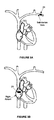
- Figure 1 illustrates one embodiment of a implantable defibrillation system
- Figure 2 illustrates one embodiment of a control system
- Figure 3A illustrates an implantable defibrillation system in the subclavian vein
- Figure 3B illustrates an implantable defibrillation system in the right atrium
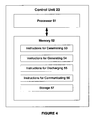
- Figure 4 illustrates one embodiment of a control unit
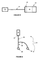
- FIG. 5 illustrates another embodiment of an implantable defibrillation system
- Figure 6 illustrates one embodiment of an electrode lead system with a bifurcated main lead
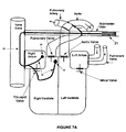
- FIGS. 7A - 7B illustrate exemplary implantable defibrillation systems with bifurcated main leads
- Figure 8 illustrates one embodiment of an electrode lead system with a single electrode on the main lead
- Figures 9A - 9B illustrate implantable defibrillation systems with a single electrode on the main lead
- Figure 10 illustrates one embodiment of an electrode lead system with a plurality of electrodes on the main lead
- Figures 11A - 11C illustrate implantable defibrillation systems with a plurality of electrodes on the main lead
- Figures 12A - 12E illustrate exemplary locations for the discharge electrode and receiving electrode
- Figure 13 illustrates a flow diagram of a method for performing atrial defibrillation.
- the present embodiments relate to defibrillation of an atrium using an implantable defibrillation system.
- the pain and/or discomfort of atrial defibrillation may be reduced by defibrillating the heart using an electrical pulse with a field strength of 100 - 700 volts/cm and a time duration of 30 - 50 microseconds.
- the electrical pulse may have a discharge voltage of at least 600 volts.
- the short time duration of the electrical pulse is intended to reduce pain during and after the discharge of the electrical pulse to the atrium. Accordingly, the pain and/or discomfort of atrial defibrillation may be reduced by controlling the contraction induced by the electrical shocks to the surrounding muscles.
- an electrical pulse with a field strength of 100-700 volts/cm across the heart muscle ensures that the electrical pulse provides the energy needed to safely and effectively defibrillate the heart and reduces the contraction to the electrically conducting muscles surrounding the heart muscle. Therefore, it may be advantageous to use an electrical pulse with a field strength of 100-700 volts/cm and a time duration of 30 - 100 microseconds when defibrillating an atrium.
- FIG. 1 shows an implantable defibrillation system 100.
- the implantable defibrillation system 100 includes a control system 20 and an electrode lead system 30.
- the control system 20 is coupled with the electrode lead system 30.
- the phrase "coupled with” includes directly connected to or indirectly connected through one or more intermediate components. Such intermediate components may include both hardware and software based components.
- the electrode lead system 30 is disposed in or around a human heart and includes a discharge electrode 32 and a receiving electrode 33.
- the control system 20 generates an electrical pulse, which is discharged from the discharge electrode 32 to the receiving electrode 33.
- the electrical pulse has a field strength of 100-700 volts/cm. To achieve this field strength, the electrical pulse may have a high voltage, for example, greater than 600 volts.
- the implantable defibrillation system 100 may include additional, different, or fewer components.
- the system 100 may include an antenna that is used for receiving or transmitting information to a communication device 60, as shown in Figure 1 .
- the antenna may send and receive information, which may be used to communicate with the control system 20.
- the antenna may be used to deliver information, such as trigger information, warning signals, distance information, voltage difference information, or software updates, to the control system 20.
- Communication between the control system 20 and communication device 60 may be, as shown in Figure 1 , wireless.
- the communication between the control system 20 and the communication device 60 may be one-way or bi-directional.
- the communication may be half or full duplex.
- the control system 20 may push communication to the communication device 60, or, alternatively or in addition thereto, respond to requests from the communication device 60.
- the communication may be used to program, set up, and monitor the control system 20, as well as interrogate the control system 20 for alarm data, sanity data, and for offloading from the device stored patient's heart activity and device activity data.
- the implantable defibrillation system 100 discussed herein may be implemented in any of a number of configurations, such as an implantable miniature atrial defibrillator, implantable heart defibrillator, defibrillation implant, an implantable cardioverter defibrillator, a pacemaker system, a ventricular defibrillation system, other system used for atrial defibrillation, or any combination thereof.
- the implantable miniature atrial defibrillator is an implantable defibrillation system 100.
- the implantable defibrillation system 100 may be a combination of a pacemaker system and an atrial defibrillator.
- the control system 20 may include a defibrillator body 21, a sensor system 22, a control unit 23, a high voltage generator 24, a high voltage capacitor 25, a high voltage switch 26, a connector 27, and a power source 15.
- the control system 20 may include additional, different, or fewer components.
- the defibrillator body 21 may be a bio-compatible housing or enclosure, canister, conductive enclosure, miniature atrial defibrillator housing, other atrial defibrillation body, or a combination thereof.
- the defibrillator body 21 may or may not be constructed from a conducting material.
- all, some, or none of the defibrillator body 21 may include or be coated with metal, such as gold or titanium.
- the defibrillator body 21 may enclose one, some, or all of the control system 20 components.
- the sensor system 22 may be disposed outside the defibrillator body 21 and electrically connected to the control unit 23, which is enclosed in the defibrillator body 21.
- the defibrillator body 21 may serve as an additional sensing and/or shocking electrode. Additional, different, or fewer components may be enclosed in the defibrillator body 21.
- the defibrillator body 21 is sized to be implanted in the heart or surrounding regions.
- the defibrillator body 21 may be sized to be implanted into pulmonary vein, the subclavian pocket, the right atrium, or a branch of the subclavian vein.
- the defibrillator body 21 may be sized to be disposed outside, around, or adjacent to the pulmonary vein, the subclavian pocket, the right atrium, or a branch of the subclavian vein.
- the defibrillator body 21 is sized to be implanted into the right atrium.
- the shape of defibrillator body 21 may be a box, rectangular volume, or other shaped volume that encloses system 20 components.
- the size (e.g., length, height, volume) of the defibrillator body 21 depends on the size of the enclosed control system 20 components.
- the defibrillator body 21 encloses at least the control unit 23, the voltage generator 24, and the high voltage capacitor 25.
- the high voltage capacitor 25 is sized to store low energy since the time duration of the electrical pulse is 30 - 100 microseconds.
- the phrase "low energy” may include energy in or around the range of 0.1 - 2.0 joules
- the phrase "high energy” may include energy in or around the range of greater than 2.0 joules.
- a low energy capacitor may have a smaller size than a high energy capacitor.
- the defibrillator body 21 may be less than 20 cubic centimeters, and preferably, 5 - 15 cubic centimeters.
- the power source 15 may be a battery, power pack, or other device that provides power to one or more of the system 20 components.
- the power source 15 may be coupled with the sensor system 22, the control unit 23, the high voltage generator 24, the high voltage capacitor 25, the high voltage switch 26, or any combination thereof.
- the power source 15 provides power to the control system 20 components.
- the sensor system 22 may include one or more sensing electrodes, electrocardiogram (ECG) sensors, breathing sensors, pressure sensors, acoustical sensors, blood pressure sensors, or any other sensors for sensing conditions of the heart.
- a condition of the heart may include muscle contraction, electrical potential, blood pressure, motion, oxygen, heart measurements, or other information relating to the operating condition of the heart, such as ECG information.
- ECG information may be information relating to the electrical activity of the heart over time, such as electrical potential of the heart or rhythm of the heart.
- the sensor system 22 may be disposed within or outside of the defibrillator body 21.
- the sensor system 22 may be a separate component or integrated with another component of the system 100, such as the electrode lead system 30.
- the sensor system 22 may include the receiving electrode 33, which is connected to the control unit 23 (e.g., through lead 31 and the connector 27).
- the receiving electrode 33 functions as an electrode for delivering an electrical pulse and also as a component of the sensor system 22, for example, by providing condition signals, such as ECG signals, to the control unit 23.
- the sensor system 22 is connected to a pressure meter disposed in a vein, such as the vena cava, or in an atrium.
- a plurality of the same or different sensors 22 may be used.
- the sensor system 22 may be operable to sense a condition of a heart and emit a condition signal that identifies the condition to the control unit 23. Sensing may include receiving, detecting, determining, monitoring, or any combination thereof.
- the condition signal may be a cardiac functioning signal that includes information about the functioning operation of the heart.
- an ECG sensor may sense an electrical potential of the heart and emit a condition signal that identifies the electrical potential of the heart.
- the sensor system 22 may provide a condition signal to the control unit 23.
- the condition signal may identify the condition of the heart.
- the condition signal may be a processed or unprocessed signal.
- the control unit 23 may process the condition signal and identify whether a state of fibrillation exists from the condition signal.
- the sensor system 22 may include a processor that identifies whether a state of fibrillation exists from the condition of the heart and emit a condition signal that indicates that an atrium is fibrillating.
- both the sensor 22 and the control unit 23 determine whether a state of fibrillation exists.
- the sensor result and the control unit result may be compared with each other.
- An electrical pulse may be generated when the sensor result, the control unit result, or both indicate that an atrium is fibrillating.
- One benefit of comparing the results is that unnecessary generation or discharge of an electrical pulse is avoided.
- the implantable defibrillation system 100 may only generate and/or discharge an electrical pulse when both the sensor result and the control unit result indicate that a state of fibrillation exists.
- the control unit 23 includes a processor 51 and memory 52.
- the control unit 23 is a computer, processing system, or a circuit for instructing and controlling the system 20 components.
- the control unit 23 is coupled with the sensor system 22, the high voltage generator 24, the high voltage capacitor 25, the high voltage switch 26, the connector 27, and the power source 15.
- the control unit 23 controls the generation of the electrical pulse, such that the electrical pulse has a field strength of 100-700 volts/cm. Accordingly, the electrical pulse has a discharge voltage of 600 volts or greater.
- the control unit 23 also controls the discharge of the electrical pulses, such that one or more of the discharged electrical pulses have a time duration of 30 - 100 microseconds.
- the processor 51 is a general processor, digital signal processor, application specific integrated circuit, field programmable gate array, analog circuit, digital circuit, combinations thereof, or other now known or later developed processor.
- the processors 23 may be a single device or a combination of devices, such as associated with a network or distributed processing. Any of various processing strategies may be used, such as multi-processing, multi-tasking, parallel processing, or the like. Processing may be local or remote. For example, a communication device may be used to transmit signals received by the processor 51 to a remote processor, which is operable to process the received signals.
- the processor 51 is responsive to instructions stored as part of software, hardware, integrated circuits, firmware, micro-code or the like.
- the processor 51 is operable to perform one or more of the acts illustrated in Figure 13 .
- the processor 51 is operable to determine whether a state of fibrillation exists, for example, in the atrium, based on one or more conditions of the heart.
- the processor 51 may analyze one or more conditions of the heart, using the information transmitted in the one or more condition signals to determine whether a state of fibrillation exists.
- the processor 51 may use a fibrillation algorithm to determine whether a state of fibrillation exists.
- the fibrillation algorithm may use ECG information to determine whether a state of fibrillation exists.
- the condition signal may include ECG information.
- the processor 51 uses the fibrillation algorithm to analyze an electric potential of the heart over time. The processor 51 may identify a state of fibrillation based on a significant change in the ECG information.
- the processor 51 may map a spatial fibrillation point to determine whether a state of fibrillation exists.
- the spatial fibrillation point may be based on one or more conditions of the heart. The conditions may be weighted according to importance or probability that the condition indicates whether a state of fibrillation exists.
- the spatial fibrillation point may represent a current operating state of all or some of the heart, such as the atrium.
- the processor 51 may map the spatial fibrillation point on a multi-dimensional space (e.g., a graph, chart, or coordinate space).
- the multi-dimensional space may include a fibrillation space and a non-fibrillation space. The spatial fibrillation point may be compared to the fibrillation space and/or the non-fibrillation space.
- mapping a spatial fibrillation point is that more than one condition may be used to determine whether a state of fibrillation exists. Since multiple conditions may be used and weighted, the accuracy of determining whether a state of fibrillation exists may be increased.
- the processor 51 is operable to determine electrical pulse parameters for defibrillation of an atrium.
- the electrical pulse parameters include a discharge voltage and an electrical pulse time duration.
- the electrical pulse parameters define an electrical pulse at the time of discharge from a discharge electrode 32.
- the electrical pulse parameters define a discharge voltage of at least 600 volts.
- the discharge voltage is determined as a function of the field strength of the electrical pulse between the discharge electrode 32 and receiving electrode 33.
- the discharge voltage may be determined, such that the field strength of the electrical pulse is 100-700 volts/cm.
- the field strength is proportional to the voltage difference between the discharge electrode 32 and the receiving electrode 33 and is inversely proportional to the distance between the discharging electrode 32 and the receiving electrode 33. Accordingly, the discharge voltage may be determined as a function of the distance from the discharge electrode 32 and the receiving electrode 33 and the desired field strength between the discharge electrode 32 and the receiving electrode 33.
- the distance from the discharge electrode 32 to the receiving electrode 33 may be the shortest distance between the discharge electrode 32 and the receiving electrode 33, as placed in the patient.
- the shortest distance may be distance D.
- the distance from the discharge electrode 32 to the receiving electrode 33 may be distance along the main lead 31 or sub leads 34.
- the distance from the discharge electrode 32 to the receiving electrode 33 may be in or around the range of 2.0 - 12.0 centimeters. Other distances may also be used.
- the processor 51 is operable to activate the high voltage generator 24, which charges the high voltage capacitor 25 according to the electrical pulse parameters.
- the high voltage generator 24 may be activated with a command signal from the control unit 23.
- the high voltage generator 24 may be controlled, such that the high voltage generator 24 charges the high voltage capacitor 25 to a voltage of at least 600 volts; or, more specifically, such that the electrical pulse will have a field strength of 100-700 volts/cm.
- the high voltage capacitor 25 may be charged to a voltage of 600 or greater volts, 1000 or greater volts, or 1300 or greater volts.
- the high voltage capacitor 25 may be charged to a voltage of 600 - 1000 volts.
- the high voltage capacitor 25 may be charged to a voltage of 1000 - 1300 volts.
- the high voltage capacitor 25 may be charged to a voltage of 1300 - 3000 volts.
- the electrical pulse may be defined to have a field strength of 100-700 volts/cm. More specifically, in one example, the electrical pulse may have a field strength of 100 - 300 volts/cm. In another example, the electrical pulse may have a field strength of 300 - 700 volts/cm.
- Figure 1 illustrates a single high voltage capacitor 25, a plurality of high voltage capacitors may be used.
- the high voltage capacitor 25 may include a capacitor bank that is operable to provide one or more electrical pulses to the high voltage switch 26.
- An electrical pulse having a field strength of 100-700 volts/cm may have a low energy. Accordingly, the size of the components may be reduced. Furthermore, an electrical pulse with a field strength of 100-700 volts/cm may ensure that the electrical pulse will defibrillate the heart, without injuring the patient's heart. A field strength of less than 100 volts/cm may be ineffective in defibrillating the heart, and a field strength of greater than 700 volts/cm may seriously injure the patient's heart.
- the control unit 23 is operable to activate the high voltage switch 26. Activating the high voltage switch may include discharging energy from the high voltage capacitor 25 to a discharge electrode 32.
- the time duration of the electrical pulse may be controlled, such that the time duration is 30 - 100 microseconds. In one example, the time duration may be 30 - 50 microseconds. In another example, the time duration may be 50 - 70 microseconds. In another example, the time duration may be 70 - 100 microseconds.
- the electrical pulse has a time duration, for example, that is less than 100 microseconds. Electrical pulses that are longer than 100 microseconds may cause substantial pain and discomfort. However, in order for the electrical pulse to effectively defibrillate the heart, the time duration may be at least 30 microseconds. Electrical pulses that are shorter than 30 microseconds may require a much higher voltage to adequately defibrillate a fibrillating heart. In one range, the electrical pulse has a time duration of 30 - 100 microseconds. In this range, the electrical pulse should minimize pain and discomfort because it induces little or no skeletal muscles contraction.
- the time duration ranges may be used with both the voltage ranges, as shown in Table 1, and the field strength ranges, as shown in Table 2.
- Table 1 Voltage/Duration Ranges 30-50 ⁇ sec 50-70 ⁇ sec 70-100 ⁇ sec 600 - 1000 Volts x x x 1000 - 1300 Volts x x x 1300+ Volts x x x x
- Table 2 Field Strength Duration Ranges 30-50 ⁇ sec 50-70 ⁇ sec 70-100 ⁇ sec 100-300 volts/cm x x x 300-700 volts/cm x x x x
- the processor 51 is operable to control the discharge of an electrical pulse train.
- the electrical pulse train may include one or more electrical pulses.
- the electrical pulses in the electrical pulse train may have the same or different durations, discharge voltages, and/or field strength values.
- an electrical pulse train may include a first electrical pulse and a second electrical pulse.
- the first electrical pulse and the second electrical pulse may have discharge voltages that are at least 600 volts and pulse durations that are 30 - 100 microseconds.
- the first electrical pulse has a discharge voltage that is at least 1000 volts and a pulse duration that is in the range of 30 - 100 microseconds.
- the second electrical pulse has a discharge voltage of less than 600 volts, a pulse duration that is less than 30 microseconds or greater than 100 microseconds, or a combination thereof.
- the memory 52 is a computer readable storage media.
- the computer readable storage media may include various types of volatile and non-volatile storage media.
- the memory 52 may be a single device or a combination of devices.
- the memory 52 may be adjacent to, part of, networked with and/or remote from the processor 51.
- the memory 52 may store information, signals, or other data.
- the memory 52 may include storage 57, which is used to store information, signals, or other data.
- the storage 57 may be used to store EKG data, monitored vital signs, patient events, log of device activity, status events, and operation parameters. Other information or data relating to or not related to atrial defibrillation may be stored in storage 57.
- the memory 52 may store instructions for the processor 51.
- the processor 51 is programmed with and executes the instructions.
- the functions, acts, methods or tasks illustrated in the figures or described herein are performed by the programmed processors 51 executing instructions stored in the memory 52.
- the functions, acts, methods or tasks are independent of the particular type of instructions set, storage media, processor or processing strategy and may be performed by software, hardware, integrated circuits, firm ware, micro-code and the like, operating alone or in combination.
- the instructions are for implementing the processes, techniques, methods, or acts described herein.
- the memory 52 may include instructions for determining fibrillation 53, instructions for generating an electrical pulse 54, instructions for discharging the electrical pulse 55, and instructions for communicating with a communication device 56.
- the memory 52 may include additional, different, or fewer instructions.
- the instructions for determining fibrillation 53 may be executed to determine whether an atrium is fibrillating.
- the instructions 53 may be executed to process signals, which are provided by sensors, to determine whether an atrium is fibrillating.
- the instructions for generating an electrical pulse 54 may be executed to generate an electrical pulse with a field strength of 100-700 volts/cm and a time duration of 30 - 100 microseconds.
- the instructions 54 may be executed to command a high voltage generator to charge a high voltage capacitor, such that an electrical pulse of at least 600 volts may be discharged from the high voltage capacitor.
- the instructions for discharging an electrical pulse 55 may be executed to deliver an electrical pulse having a field strength of 100-700 volts/cm and a time duration of 30 - 100 microseconds from a discharge electrode to a receiving electrode.
- the instructions for communicating with a communication device 56 may be executed to communicate with a communication device in, around, or outside of the defibrillation system.
- the high voltage generator 24 is a generator that charges the high voltage capacitor 25.
- the high voltage capacitor 25 may store energy, such that an electrical pulse may be provided to a discharge electrode in accordance with the electrical pulse parameters.
- the high voltage generator 24 may charge the high voltage capacitor 25, such that an electrical pulse, which has a voltage of at least 600 volts may be provided to the discharge electrode.
- a shock pulse generator includes the high voltage generator 24, the high voltage capacitor 25, and the high voltage switch 26.
- the high voltage capacitor 25 is a capacitor bank, where more than one capacitor is used to store energy, such that the energy may be selectively discharged, for example, in the pulse train option.
- the high voltage switch 26 is a switch that may be activated to discharge the energy from the high voltage capacitor 25 to a discharge electrode.
- the high voltage switch 26 may be activated by the control unit 23 or an activation circuit.
- the control unit 23 may activate the high voltage switch when the high voltage capacitor has been charged to the specified voltage.
- the high voltage switch 26 includes an activation circuit that activates the high voltage switch when one or more high voltage capacitor(s) have been charged to the specified voltage.
- the activation circuit may include a gas discharge tube, silicone controlled rectifier, light-activated silicon-controlled rectifier. Once activated, the high voltage switch 26 allows the high voltage capacitor 25 to discharge, thus applying a defibrillation shock to the discharge electrode.
- the high voltage switch 26 may reverse the high voltage polarity during the defibrillation pulse.
- the high voltage switch 26 may safely discharge the high voltage capacitor 25 if fibrillation stops while the high voltage capacitor 25 is charging.
- the connector 27 is a mating connector, a lead connector, or other connector for coupling the electrode lead system 30 with the control system 20.
- the connector 27 is a mating connector that connects the electrode lead 31 to the high voltage switch 26 in the defibrillator body 21.
- the connector 27 couples a discharge electrode, which may be disposed in the defibrillator body 21, with a receiving electrode.
- the power source 15 is a battery, power pack, or other device that provides power to one or more of the system 20 components.
- the power source 15 may be rechargeable.
- the power source 15 needed for charging the capacitor may be smaller than a power source 15 for charging a ventricular defibrillation capacitor.
- the battery drain caused by the sensing electronics module remains similar, thus the proportional size saving for the battery is smaller.
- Periodic battery recharging may reduce the size of the battery to substantially the size needed to produce the defibrillation shocks. In a device intended to deliver only few such shocks before being replaced or recharged, the battery size may be greatly reduced.
- a separate battery is used for storing energy needed for defibrillation while a second battery, optionally rechargeable, powers the sensing and control electronics.
- the power source 15 may be inductively rechargeable, such that the power source 15 does not need to be removed from the patient to recharge.
- the control system 20 may include a communication device, such as a microphone, a radio frequency (RF) device, a wireless communication device, alarm, notification device, or a combination thereof.
- the communication device may be used to transmit messages to another communication device, for example, positioned in a control center, such as a hospital or medical facility.
- the transmitted message may be fibrillation message that indicates that the patient's atrium is fibrillating and that an electrical pulse has been or will be discharged automatically.
- the communication device may be a radio frequency (RF) device that is used to communicate with another RF device, such as a mobile phone. Any type of message may be transmitted, for example, a phone message, a text message, a session initiation protocol message, a multimedia messaging service message, or other type of audio or data message.
- the implantable defibrillation system 100 includes a microphone that is used for receiving information from an ultrasonic transducer in contact with the patient's body.
- the implantable defibrillation system 100 includes an alarm, such as a vibration device or acoustical device, which provides a patient with a warning before discharging the electrical pulse.
- the warning may be provided one or more seconds before the discharge. Accordingly, the patient may have time to prepare for the electrical pulse, for example, by pulling off to the side of the road when driving.
- the alarm may be provided such that the patient knows to go to a hospital or medical facility and has time to make it to the hospital or medical facility.
- a discharge pulse may be automatically or manually discharged, such that the defibrillation is conducted under the supervision of a medical expert.
- the detection and alarm are automatic; whereas, the discharge of the defibrillation electrical pulse or pulse train is manual.
- the implantable defibrillation system 100 includes a positioning system, such as a location device or global positioning system.
- the positioning system is operable to determine a physical location of the implantable defibrillation system 100.
- the physical location may be transmitted to a control center, such as a hospital or medical facility.
- a communication device may transmit a fibrillation message to a control center.
- the fibrillation message may include the patient's location, since the implantable defibrillation system 100 is implanted in the patient.
- implantable defibrillation system 100 includes an attachment device, such as a hook device, that is coupled with a discharge electrode 32 or a receiving electrode 33 of the electrode lead system.
- the attachment device is operable to attach the discharge electrode or receiving electrode to a wall of the heart. Attachment may include mounting, securing, or positioning an electrode in the heart. When attached, an electrode may or may not be capable of moving relative to the heart.
- the electrode lead system 30 may include a lead 31 and at least one receiving electrode 33. Additional, different, or fewer components may be provided. For example, a plurality of leads 31 and/or electrodes 32 may be provided.
- the electrode lead 31 may be a wire, rod, flexible arm, clamp, or other device for positioning the at least one receiving electrode 33 in the heart.
- the lead 31 couples the discharge electrode 32 and the receiving electrode 33.
- the lead 31 may be electrically conductive, such that electrical signals may be transmitted between the discharge electrode 32 and the receiving electrode 33.
- the lead 31 may be used to transmit electrical signals between the discharge electrode 32 and the receiving electrode 33.
- the electrical signals may include condition signals, electrical pulses, or other communication signals.
- the control system 20 may include the discharge electrode 32.
- the defibrillator body 21 may enclose the discharge electrode 32. Accordingly, the connector 27 connects the discharge electrode 32 to main lead 31, such that electrical signals may be transmitted between the discharge electrode 32 and the receiving electrode 33.
- the implantable defibrillation system 100 includes a communication device 60.
- the communication device 60 may be part of or external to the system 100.
- the communication device 60 may be part of a different system.
- the communication device 60 may communicate with one or more components in the system 100, such as the control unit 23.
- the communication device 60 may be a radio frequency device or other wireless device.
- the control unit 23 may detect fibrillation and send a warning message to a radio in a hospital. The warning message may inform the medical staff at the hospital that the control system 20 detected a fibrillating atrium.
- the communication device 60 may be used to transmit signals to the communication device 60.
- control system 20 may detect a fibrillating right atrium and warn the patient that the heart is fibrillating. Once the patient arrives at the hospital, a medical attendant may use the communication device 60 to transmit a control signal to the control system 20, such that an electrical pulse is discharged from the control system 20. In this example, the medical attendant may supervise the defibrillation of the heart.
- one or more electrodes may be used for sensing (e.g., with the sensing system 22), for shocking (e.g., with the high voltage generator 24, the high voltage capacitor 25, and high voltage switch 26), or a combination thereof.
- the electrodes and/or the electrical shocks may be disposed in the right atrium (e.g. near the AV node); the left atrium (e.g.
- the defibrillator body 21 may be used as a sensing and/or shocking electrode.
- At least two electrodes are used for sensing and/or shocking.
- the at least two electrodes may be any combination of shocking electrodes and sensing electrodes.
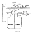
- Shocking electrodes may be located in the right atrium; the left atrium; the right ventricle (e.g., near the pulmonary valve); or the pulmonary artery near the pulmonary valve.
- Sensing electrodes may be located in the right atrium; the left atrium; the right ventricle (e.g., near the pulmonary valve); the pulmonary artery near the pulmonary valve; the apex of the RV; or the defibrillator body 21.
- Figures 6 , 8 , and 10 illustrate examples of different embodiments of the implantable defibrillation system 100.
- Figures 7 , 9 , and 11 illustrate different locations for the electrodes in the implantable defibrillation system 100.
- the examples shown in Figures 6 - 11 are not limiting. Other embodiments of the implantable defibrillation system 100 and/or other locations of the electrodes may be used for atrial defibrillation.
- FIG. 6 illustrates an electrode lead system 30 with a bifurcated lead.
- the electrode lead 31 includes a main lead 35 and sub leads 34.
- An electrode, a sensor, or a combination thereof may be disposed at one end of the sub leads 34.
- the other ends of the sub leads 34 may be coupled with the main lead 35.
- a first sub lead may include a first receiving electrode at one end of the first sub lead
- a second sub lead may include a second receiving electrode at one end of the second sub lead.
- the other ends of the first and second sub leads may be connected to the main lead 35.
- the lengths of the main lead 35 and one or more sub leads 34 may be the same or different.
- a first sub lead may be longer than a second sub lead.
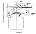
- Figures 7A and 7B illustrate electrode lead systems 30 with bifurcated leads, as positioned in the patient.
- Figure 7A illustrates a bifurcated lead that is located in the subclavian vein, however, may be placed in the vena cava.
- the main lead 35 traverses the subclavian vein and enters the vena cava.
- the two sub leads 34 enter the Right Atrium (RA) and the Right Ventricle (RV), respectively.
- the longer sub-lead 34 enters the RV through the tricuspid valve.
- the distal ends of the sub leads are examples of the sub leads.
- FIG. 34 may be anchored to walls of the Right Atrium (RA) (in various locations including the AV node or the SA node) and the Right Ventricle (RV) such that the shock delivering electrodes are in contact to the walls of the right atrium and the right ventricle.
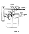
- Figure 7B illustrates a bifurcated lead as positioned in the patient.
- the defibrillator body 21 may be located in a side branch of the subclavian vein.
- the main lead 35 enters the heart through the vena cava.
- a first sub-lead 34, having a distal first electrode 32, is located in the Right Atrium (RA).
- the discharge electrode 32 may be anchored to a RA wall, preferably near the pulmonary valve.
- a second, preferably longer sub-lead 34 is inserted via the coronary sinus.
- the second sub-lead 34 comprises a receiving electrode 33 which is located in the Left Atrium (LA) wall near the pulmonary valve.
- Figure 8 illustrates an electrode lead system 30 with a receiving electrode 33 disposed at one end of the electrode lead 31.
- the electrode lead 31 includes a main lead 35.
- An electrode, a sensor, or a combination thereof is disposed on the main lead 35.
- the main lead 35 may be coupled with the control system 20.
- the discharge electrode 32 may be disposed in the defibrillator body 21, for example, as shown in Figure 5 .
- the defibrillator body 21 may be connected to the lead system 31 via a special connector.
- the defibrillator body 21 may be displaced from the leads, for example, subcutaneously implanted, like current pacemakers and defibrillators.
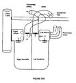
- Figures 9A and 9B illustrate electrode lead systems 30 with a discharge electrode 32 disposed at one end of the electrode lead 31, as positioned in the patient.
- Figure 9A illustrates an electrode lead system 30 with a receiving electrode 33 disposed at one end of the electrode lead 31.
- the defibrillator body 21, acting as, or including a discharge electrode 32 may be located in the Right Atrium (RA).
- the defibrillator body 21 may be anchored to the RA wall. Accordingly, the shock delivering electrode, such as the discharge electrode 32, is in contact to the RA wall.
- a single lead having a receiving electrode 33 enters the Right Ventricle (RV) through the Tricuspid valve.
- RV Right Ventricle
- the receiving electrode 33 may be anchored to wall of the RV, preferably such that discharge electrode 33 is in contact to the RV wall.
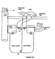
- Figure 9B illustrates a defibrillator body 21, acting as, or comprising a discharge electrode 32.
- the defibrillator body 21 and/or the discharge electrode 32 may be located in the RA.
- the defibrillator body 21 is anchored to the RA wall.
- the discharge electrode 21 is in contact to the RA wall.
- a single lead 31 includes a receiving electrode 33 that is inserted into the Coronary Sinus or one of the veins leading to it.
- Figure 10 illustrates an electrode lead system 30 with a pigtail lead.
- a plurality of electrodes, sensors, or a combination thereof is disposed on the main lead 31.
- a central electrode 38 may be disposed on the main lead 31 between the receiving electrode 33 and the control system 20.
- the central electrode 38 may be a sensing electrode (e.g., part of the sensing system 22) or a discharge electrode 32 for discharging the electrical pulse.
- FIG 11A illustrates more than one electrode on the main lead 31.
- the defibrillator body 21 may be located in a side branch of the subclavian vein.
- the main lead 31 includes at least a central electrode 38 and a receiving electrode 33.
- the main lead 31 enters the heart through the vena cava.
- the central electrode 38 is positioned in the Right Atrium (RA).
- the distal section of the main lead 31 is inserted via the tricuspid valve into the RV.
- the receiving electrode 33 which is located in the Right Ventricle (RV), may be anchored to the RV wall near the pulmonary valve.
- RV Right Ventricle
- Figure 11B also illustrates more than one electrode on the main lead 31 as positioned in the patient.
- the defibrillator body 21 is located in the subclavian vein.
- the main lead 31 includes a central electrode 38 and a receiving electrode 33.
- the main lead 31 enters the heart through the vena cava.
- the central electrode is located in the Right Atrium (RA).
- the central electrode 38 may be anchored to the RA wall, preferably near the pulmonary valve.
- the receiving electrode 33 of the main lead 31 is inserted into the coronary sinus or one of the veins leading to it.
- Figure 11C also illustrates more than one electrode on the main lead 31 as positioned in the patient.
- the defibrillator body 21 may be located in a side branch of the subclavian vein.
- the main lead 31 includes at least two, and optionally three electrodes.
- the main lead 31 enters the heart through the vena cava.
- the first central electrode 38 which may be a sensing electrode or discharging electrode, is positioned in the Right Atrium (RA).
- RA Right Atrium
- a central section of the main lead 31 is inserted via the tricuspid valve into the RV.
- the second central electrode 38 which is located in the Right Ventricle (RV), may be anchored to the RV wall near the pulmonary valve.
- the receiving section of the main lead 31 is inserted via the pulmonary valve into the pulmonary artery.
- the receiving electrode 33 is located in the pulmonary artery.
- the discharge electrode 32 and receiving electrode 33 may be disposed in the heart.
- Figures 12A - 12E show examples of different locations of the various electrodes, such as the sensing electrode, discharge electrode 32 and receiving electrode 33.
- the electrode 120 may be a sensing electrode, discharge electrode 32, receiving electrode 33, central electrode 39, or any combination thereof.
- the position of the electrode 120 in Figures 12A - 12E may the physical location of the electrode or the physical location of the electrical shock provided by the electrode.
- the actual position of the electrode 120 may be provided in the Coronary Sinus (or one of the veins surrounding the Left Atrium) and provide an electrical shock to the left atrium.
- the electrical shock to the left atrium may be illustrated as the position of the electrode 120, even though the actual electrode may be disposed away from or adjacent to the position of the electrode 120 in the illustrations.
- Figure 12A shows a first electrode 120 that is located near the antrioventricular (AV) node inside the RA.
- the first electrode 120 may be inserted via the vena cava.
- a second electrode 120 is located at the wall of the LA (or intra-atrial septum) near the pulmonary valve.
- the second electrode 120 is preferably inserted via the coronary sinus.
- Figure 12B shows a first electrode 120 located at the RV near pulmonary valve.
- the first electrode 120 may be inserted via the vena cava and the RV valve.
- a second electrode 120 is located at the wall of the left atrium (LA) (or intra-atrial septum) near the pulmonary valve.
- LA left atrium
- the second electrode 120 may be inserted via the coronary sinus.
- Figure 12C shows a first electrode 120 located at the superior vena cava.
- a second electrode 120 is located at the wall of the LA (or intra-atrial septum) near the pulmonary valve.
- the second electrode 120 may be inserted via the coronary sinus.
- a first electrode 120 may be located at the superior vena cava and a second electrode 120 is located in the RV near the pulmonary valve.
- the second electrode 120 may be inserted via the tricuspid valve.
- a third electrode 120 at the RV apex may be inserted via the tricuspid valve and used for sensing and/or ventricular defibrillation and/or pacing.
- a first electrode 120 may be located in the pulmonary artery, near the pulmonary valve.
- the first electrode may be provided in the pulmonary artery via the right atrium and the tricuspid valve to the right ventricle. Once in the right ventricle, the first electrode 120 may be moved through the pulmonary valve to the pulmonary artery.
- a second electrode 120 may be located in the Coronary Sinus or one of the veins leading to it.
- the electrode lead system 30 includes one or more additional electrodes that are operable to deliver cardiac pacing pulses and/or ventricular defibrillation.
- additional electrodes that are operable to deliver cardiac pacing pulses and/or ventricular defibrillation are that the defibrillation system 100 may be used when atrial fibrillation progresses to ventricular fibrillation or ventricular arrhythmia or when the delivered atrial defibrillation shock induces ventricular fibrillation or ventricular arrhythmia.
- the additional electrodes may also be used such that the delivered atrial defibrillation shock is synchronized to the natural or paced ventricular beat.
- One benefit of synchronizing the shock and the natural or paced ventricular beat is that the probability that the delivered atrial defibrillation shock would cause ventricular fibrillation or ventricular arrhythmia is reduced.
- the implantable defibrillation system 100 includes a drug delivering system.
- the drug delivery system may include a drug pump that is capable of injecting a drug into a right atrium.
- the drug pump may be computer controlled or manually controlled.
- the drug pump may be controlled by the control unit 23.
- the control unit 23 may activate the drug pump prior to the discharge of the electrical pulse.
- the drug delivery may further reduce the pain and/or discomfort of atrial defibrillation.
- delivering a drug directly into the heart may act quicker than delivering the drug using intravenous (IV) therapy because drugs that are provided using IV therapy may need to travel to the heart. Accordingly, the travel time may slow down the defibrillation process.
- IV intravenous
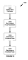
- Figure 13 is a flow diagram illustrating a method 1300 for defibrillating an atrium with an implantable defibrillation system.
- the method 1300 includes detecting when an atrium of a heart fibrillates 1301, setting electrical pulse parameters 1302, generating an electrical pulse 1303, and discharging an electrical pulse 1304.
- the method 1300 may include additional, different, or fewer acts.
- an implantable defibrillation system detects when an atrium of a heart fibrillates. Detecting fibrillation may include receiving sensor signals, such as condition signals, from one or more sensors. The sensor signals may be processed to determine whether an atrium is in a fibrillation state. Processing the sensor signals may include signal processing, spatial comparisons, or other processes of determining whether a sensor signal indicates that an atrium is fibrillating.
- electrical pulse parameters are set prior to or upon detection of atrial defibrillation.
- the electrical pulse parameters define characteristics, values, boundaries, or limitations of the electrical pulse.
- the electrical pulse parameters may define a discharge voltage and a time duration of one or more electrical pulses.
- the electrical pulse parameters may be determined as a function of a distance between a discharge electrode and a receiving electrode and/or voltage difference between a discharge electrode and a receiving electrode.
- the electrical pulse parameters may define an electrical pulse with a field strength of 100 - 700 volts/cm. Accordingly, the electrical pulse may have a defibrillation voltage of at least 600 volts.
- the implantable defibrillation system generates an electrical pulse in accordance with the electrical pulse parameters. Generating an electrical pulse may include charging a high voltage capacitor with energy, such that an electrical pulse in accordance with the electrical pulse parameters may be discharged from the high voltage capacitor.
- the implantable defibrillation system discharges the electrical pulse to an atrium of the heart using a discharge electrode and a receiving electrode. Discharging the electrical pulse may include providing energy from a high voltage capacitor to a discharge electrode. Discharging the electrical pulse may also include controlling the discharge, such that a time duration of the electrical pulse is 30 - 100 microseconds.
- the method 1300 may further include discharging an electrical pulse train that includes the first electrical pulse and a second electrical pulse.
- the first electrical pulse and a second electrical pulse may have the same or different discharge voltage, time duration, field strength, or a combination thereof.
- two or more pulses may be included in the pulse train.
- the electrical pulses of the electrical pulse train may be monophasic or biphasic.
- the pulse train may include electrical pulses that have or do not have the same polarity as the other electrical pulses in the electrical pulse train.
- the method 1300 may include other acts.
- the method 1300 may include implanting the implantable defibrillation system into a heart.
- the implantable defibrillation system may be implanted such that a distance between the discharge electrode and the receiving electrode is less than 3 centimeters.
- the method 1300 includes notification acts.
- the method 1300 may be used to notify or communicate with a patient or a control center, such as a hospital or a medical control center.
- a notification system may be activated.
- the notification is operable to notify a patient of the first electrical pulse before discharging the first electrical pulse to the atrium of the heart.
- Notifying the patient may include activating a vibration device or acoustic device.
- a message may be transmitted to a communication device.
- the message may be fibrillation message that indicates that an atrium is fibrillating and an electrical pulse has been or will be discharged.
- Other message may be transmitted to the communication device, such as a location message that indicates the location of the implantable defibrillation system.
- the location may be determined using a positioning system, such as a location device or global positioning system.
- the method 1300 may also include pain reduction acts.
- the pain reduction acts may include delivering a drug to the heart using the implantable defibrillation system before discharging the first electrical pulse to the atrium of the heart. Other pain reduction acts may be provided.
Description
- The present embodiments relate to atrial defibrillation. More specifically, the present embodiments relate to defibrillation of the atria using an implantable defibrillation system.
- Atrial fibrillation is a cardiac arrhythmia (abnormal heart rhythm) that involves at least one of the upper chambers of the heart, such as the right atrium or the left atrium. To defibrillate a fibrillating atrium, an electrical pulse is delivered to the heart at a specific moment in the cardiac cycle. Atrial defibrillation, using an implantable atrial defibrillation system, includes automatically detecting atrial fibrillation and automatically delivering the electrical pulse to the upper chambers of the heart. The delivery of the electrical pulse may be a painful procedure for the patient and may hinder the use of automatically activated implantable atrial defibrillators.
EP 0 764 451 B1 , which discloses all the features of the preamble of claim 1, discloses an implantable heart defibrillator for defibrillation with low-energy pulses.From one perspective, delivering an electrical pulse with an energy that is too high may cause pain for the patient. However, from a different perspective, if the energy is too low, the defibrillation will not be successful. Accordingly, atrial defibrillation that is safe, effective, and/or reduces the discomfort to a patient may be desired. - In order to address the need for improved atrial defibrillation, an implantable atrial defibrillator and method for use are disclosed herein. According to one aspect, an implantable heart defibrillator for use with an electrode lead system is provided. The implantable heart defibrillator includes an electrode lead connector that is connectable to the electrode lead system. A sensor is connected to the electrode lead connector. The sensor is operable to sense a condition of a heart and emit a condition signal that identifies the condition. A control unit is connected to the sensor. The control unit is operable to identify whether a state of fibrillation exists from the condition signal and emit a command signal if the state of fibrillation exists. A shock pulse generator is connected to the control unit and the electrode lead connector. The shock pulse generator is operable to emit at least one defibrillation shock to the electrode lead connector upon receipt of the command signal. The at least one defibrillation shock comprises at least one pulse having a voltage of more than 600 volts and a time duration of 30 to 100 microseconds.
- In another aspect, a method for defibrillating an atrium with an implantable defibrillation system is provided. The method includes detecting when an atrium in the heart is in a state of fibrillation. At least one electrical pulse parameter is set. The at least one electrical pulse parameter defines an electrical pulse having a defibrillation voltage of at least 600 volts and a pulse duration of 30 - 100 microseconds. A first electrical pulse in accordance with the at least one electrical pulse parameter is generated and discharged to an atrium of the heart using a discharge electrode and a receiving electrode of the implantable defibrillation system. The defibrillation voltage of the first electrical pulse is at least 600 volts and the pulse duration is 30 - 100 microseconds.
- In yet another aspect, a system for defibrillation of an atrium of a heart is provided. The system includes a memory and a processor in communication with the memory. The memory includes processor readable instructions that are executable with the processor. The processor readable instructions are executed to receive condition signals from one or more sensors, determine when the atrium of the heart is in a fibrillation state using the cardiac functioning signals, generate a first defibrillation electrical pulse with a field strength of 100 - 700 volts/cm between a discharge electrode and a receiving electrode and a time duration of 30 - 100 microseconds, and discharge the first defibrillation electrical pulse from the discharge electrode and a receiving electrode to defibrillate the atrium of the heart.
- The present embodiments may be better understood with reference to the following drawings and description. Non-limiting and non-exhaustive embodiments are described with reference to the following drawings. The components in the drawings are not necessarily to scale, emphasis instead being placed upon illustrating the principles of the present embodiments. In the drawings, like referenced numerals designate corresponding parts throughout the different views.
-
Figure 1 illustrates one embodiment of a implantable defibrillation system; -
Figure 2 illustrates one embodiment of a control system; -
Figure 3A illustrates an implantable defibrillation system in the subclavian vein, andFigure 3B illustrates an implantable defibrillation system in the right atrium; -
Figure 4 illustrates one embodiment of a control unit; -
Figure 5 illustrates another embodiment of an implantable defibrillation system; -
Figure 6 illustrates one embodiment of an electrode lead system with a bifurcated main lead; -
Figures 7A - 7B illustrate exemplary implantable defibrillation systems with bifurcated main leads; -
Figure 8 illustrates one embodiment of an electrode lead system with a single electrode on the main lead; -
Figures 9A - 9B illustrate implantable defibrillation systems with a single electrode on the main lead; -
Figure 10 illustrates one embodiment of an electrode lead system with a plurality of electrodes on the main lead; -
Figures 11A - 11C illustrate implantable defibrillation systems with a plurality of electrodes on the main lead; -
Figures 12A - 12E illustrate exemplary locations for the discharge electrode and receiving electrode; and -
Figure 13 illustrates a flow diagram of a method for performing atrial defibrillation. - The present embodiments relate to defibrillation of an atrium using an implantable defibrillation system. In one embodiment, the pain and/or discomfort of atrial defibrillation may be reduced by defibrillating the heart using an electrical pulse with a field strength of 100 - 700 volts/cm and a time duration of 30 - 50 microseconds. The electrical pulse may have a discharge voltage of at least 600 volts. The short time duration of the electrical pulse is intended to reduce pain during and after the discharge of the electrical pulse to the atrium. Accordingly, the pain and/or discomfort of atrial defibrillation may be reduced by controlling the contraction induced by the electrical shocks to the surrounding muscles. In order to control the contraction induced by the electrical shock, an electrical pulse with a field strength of 100-700 volts/cm across the heart muscle ensures that the electrical pulse provides the energy needed to safely and effectively defibrillate the heart and reduces the contraction to the electrically conducting muscles surrounding the heart muscle. Therefore, it may be advantageous to use an electrical pulse with a field strength of 100-700 volts/cm and a time duration of 30 - 100 microseconds when defibrillating an atrium.
-
Figure 1 shows animplantable defibrillation system 100. Theimplantable defibrillation system 100 includes acontrol system 20 and anelectrode lead system 30. Thecontrol system 20 is coupled with theelectrode lead system 30. Herein, the phrase "coupled with" includes directly connected to or indirectly connected through one or more intermediate components. Such intermediate components may include both hardware and software based components. Theelectrode lead system 30 is disposed in or around a human heart and includes adischarge electrode 32 and a receivingelectrode 33. Thecontrol system 20 generates an electrical pulse, which is discharged from thedischarge electrode 32 to thereceiving electrode 33. The electrical pulse has a field strength of 100-700 volts/cm. To achieve this field strength, the electrical pulse may have a high voltage, for example, greater than 600 volts. - Alternatively, the
implantable defibrillation system 100 may include additional, different, or fewer components. For example, thesystem 100 may include an antenna that is used for receiving or transmitting information to acommunication device 60, as shown inFigure 1 . As will be discussed below, the antenna may send and receive information, which may be used to communicate with thecontrol system 20. The antenna may be used to deliver information, such as trigger information, warning signals, distance information, voltage difference information, or software updates, to thecontrol system 20. Communication between thecontrol system 20 andcommunication device 60 may be, as shown inFigure 1 , wireless. - The communication between the
control system 20 and thecommunication device 60 may be one-way or bi-directional. The communication may be half or full duplex. Further, thecontrol system 20 may push communication to thecommunication device 60, or, alternatively or in addition thereto, respond to requests from thecommunication device 60. The communication may be used to program, set up, and monitor thecontrol system 20, as well as interrogate thecontrol system 20 for alarm data, sanity data, and for offloading from the device stored patient's heart activity and device activity data. - The
implantable defibrillation system 100 discussed herein may be implemented in any of a number of configurations, such as an implantable miniature atrial defibrillator, implantable heart defibrillator, defibrillation implant, an implantable cardioverter defibrillator, a pacemaker system, a ventricular defibrillation system, other system used for atrial defibrillation, or any combination thereof. For example, in the illustration above, the implantable miniature atrial defibrillator is animplantable defibrillation system 100. In another example, theimplantable defibrillation system 100 may be a combination of a pacemaker system and an atrial defibrillator. - As shown in
Figure 2 , thecontrol system 20 may include adefibrillator body 21, asensor system 22, acontrol unit 23, ahigh voltage generator 24, ahigh voltage capacitor 25, ahigh voltage switch 26, aconnector 27, and apower source 15. Thecontrol system 20 may include additional, different, or fewer components. - The
defibrillator body 21 may be a bio-compatible housing or enclosure, canister, conductive enclosure, miniature atrial defibrillator housing, other atrial defibrillation body, or a combination thereof. Thedefibrillator body 21 may or may not be constructed from a conducting material. For example, all, some, or none of thedefibrillator body 21 may include or be coated with metal, such as gold or titanium. Thedefibrillator body 21 may enclose one, some, or all of thecontrol system 20 components. For example, thesensor system 22 may be disposed outside thedefibrillator body 21 and electrically connected to thecontrol unit 23, which is enclosed in thedefibrillator body 21. In another example, as discussed below, thedefibrillator body 21 may serve as an additional sensing and/or shocking electrode. Additional, different, or fewer components may be enclosed in thedefibrillator body 21. - The
defibrillator body 21 is sized to be implanted in the heart or surrounding regions. For example, as shown inFigure 3A , thedefibrillator body 21 may be sized to be implanted into pulmonary vein, the subclavian pocket, the right atrium, or a branch of the subclavian vein. In another example, thedefibrillator body 21 may be sized to be disposed outside, around, or adjacent to the pulmonary vein, the subclavian pocket, the right atrium, or a branch of the subclavian vein. In one example, as shown inFigure 3B , thedefibrillator body 21 is sized to be implanted into the right atrium. The shape ofdefibrillator body 21 may be a box, rectangular volume, or other shaped volume that enclosessystem 20 components. - The size (e.g., length, height, volume) of the
defibrillator body 21 depends on the size of theenclosed control system 20 components. In one embodiment, as shown inFigure 2 , thedefibrillator body 21 encloses at least thecontrol unit 23, thevoltage generator 24, and thehigh voltage capacitor 25. As discussed below, thehigh voltage capacitor 25 is sized to store low energy since the time duration of the electrical pulse is 30 - 100 microseconds. As used herein, the phrase "low energy" may include energy in or around the range of 0.1 - 2.0 joules, and the phrase "high energy" may include energy in or around the range of greater than 2.0 joules. A low energy capacitor may have a smaller size than a high energy capacitor. Accordingly, thedefibrillator body 21 may be less than 20 cubic centimeters, and preferably, 5 - 15 cubic centimeters. Thepower source 15 may be a battery, power pack, or other device that provides power to one or more of thesystem 20 components. Thepower source 15 may be coupled with thesensor system 22, thecontrol unit 23, thehigh voltage generator 24, thehigh voltage capacitor 25, thehigh voltage switch 26, or any combination thereof. Thepower source 15 provides power to thecontrol system 20 components. - The
sensor system 22 may include one or more sensing electrodes, electrocardiogram (ECG) sensors, breathing sensors, pressure sensors, acoustical sensors, blood pressure sensors, or any other sensors for sensing conditions of the heart. A condition of the heart may include muscle contraction, electrical potential, blood pressure, motion, oxygen, heart measurements, or other information relating to the operating condition of the heart, such as ECG information. ECG information may be information relating to the electrical activity of the heart over time, such as electrical potential of the heart or rhythm of the heart. - The
sensor system 22 may be disposed within or outside of the defibrillator body 21.The sensor system 22may be a separate component or integrated with another component of thesystem 100, such as theelectrode lead system 30. For example, as shown inFigure 1 , thesensor system 22 may include the receivingelectrode 33, which is connected to the control unit 23 (e.g., throughlead 31 and the connector 27). In this example, the receivingelectrode 33 functions as an electrode for delivering an electrical pulse and also as a component of thesensor system 22, for example, by providing condition signals, such as ECG signals, to thecontrol unit 23. In another example, thesensor system 22 is connected to a pressure meter disposed in a vein, such as the vena cava, or in an atrium. Optionally, a plurality of the same ordifferent sensors 22 may be used. - The
sensor system 22 may be operable to sense a condition of a heart and emit a condition signal that identifies the condition to thecontrol unit 23. Sensing may include receiving, detecting, determining, monitoring, or any combination thereof. The condition signal may be a cardiac functioning signal that includes information about the functioning operation of the heart. In one example, an ECG sensor may sense an electrical potential of the heart and emit a condition signal that identifies the electrical potential of the heart. Thesensor system 22 may provide a condition signal to thecontrol unit 23. The condition signal may identify the condition of the heart. The condition signal may be a processed or unprocessed signal. - The
control unit 23 may process the condition signal and identify whether a state of fibrillation exists from the condition signal. Alternatively, thesensor system 22 may include a processor that identifies whether a state of fibrillation exists from the condition of the heart and emit a condition signal that indicates that an atrium is fibrillating. - In one advantageous embodiment, both the
sensor 22 and thecontrol unit 23 determine whether a state of fibrillation exists. The sensor result and the control unit result may be compared with each other. An electrical pulse may be generated when the sensor result, the control unit result, or both indicate that an atrium is fibrillating. One benefit of comparing the results is that unnecessary generation or discharge of an electrical pulse is avoided. For example, theimplantable defibrillation system 100 may only generate and/or discharge an electrical pulse when both the sensor result and the control unit result indicate that a state of fibrillation exists. - As shown in
Figure 4 , thecontrol unit 23 includes aprocessor 51 andmemory 52. Thecontrol unit 23 is a computer, processing system, or a circuit for instructing and controlling thesystem 20 components. Thecontrol unit 23 is coupled with thesensor system 22, thehigh voltage generator 24, thehigh voltage capacitor 25, thehigh voltage switch 26, theconnector 27, and thepower source 15. Thecontrol unit 23 controls the generation of the electrical pulse, such that the electrical pulse has a field strength of 100-700 volts/cm. Accordingly, the electrical pulse has a discharge voltage of 600 volts or greater. Thecontrol unit 23 also controls the discharge of the electrical pulses, such that one or more of the discharged electrical pulses have a time duration of 30 - 100 microseconds. - The
processor 51 is a general processor, digital signal processor, application specific integrated circuit, field programmable gate array, analog circuit, digital circuit, combinations thereof, or other now known or later developed processor. Theprocessors 23 may be a single device or a combination of devices, such as associated with a network or distributed processing. Any of various processing strategies may be used, such as multi-processing, multi-tasking, parallel processing, or the like. Processing may be local or remote. For example, a communication device may be used to transmit signals received by theprocessor 51 to a remote processor, which is operable to process the received signals. Theprocessor 51 is responsive to instructions stored as part of software, hardware, integrated circuits, firmware, micro-code or the like. Theprocessor 51 is operable to perform one or more of the acts illustrated inFigure 13 . - The
processor 51 is operable to determine whether a state of fibrillation exists, for example, in the atrium, based on one or more conditions of the heart. As used herein, the phrase "based on" may include as a function of, depending on, as a result of, or by analyzing. Determining whether a state of fibrillation exists may include receiving one or more condition signals from thesensor system 22. Theprocessor 51 may analyze one or more conditions of the heart, using the information transmitted in the one or more condition signals to determine whether a state of fibrillation exists. - The
processor 51 may use a fibrillation algorithm to determine whether a state of fibrillation exists. The fibrillation algorithm may use ECG information to determine whether a state of fibrillation exists. The condition signal may include ECG information. In one example, theprocessor 51 uses the fibrillation algorithm to analyze an electric potential of the heart over time. Theprocessor 51 may identify a state of fibrillation based on a significant change in the ECG information. - Alternatively, or additionally, the
processor 51 may map a spatial fibrillation point to determine whether a state of fibrillation exists. The spatial fibrillation point may be based on one or more conditions of the heart. The conditions may be weighted according to importance or probability that the condition indicates whether a state of fibrillation exists. The spatial fibrillation point may represent a current operating state of all or some of the heart, such as the atrium. Theprocessor 51 may map the spatial fibrillation point on a multi-dimensional space (e.g., a graph, chart, or coordinate space). The multi-dimensional space may include a fibrillation space and a non-fibrillation space. The spatial fibrillation point may be compared to the fibrillation space and/or the non-fibrillation space. When the spatial point is in the non-fibrillation space, an atrium is not fibrillating. When the spatial point is in the fibrillation space, an atrium is fibrillating. One benefit of mapping a spatial fibrillation point is that more than one condition may be used to determine whether a state of fibrillation exists. Since multiple conditions may be used and weighted, the accuracy of determining whether a state of fibrillation exists may be increased. - The
processor 51 is operable to determine electrical pulse parameters for defibrillation of an atrium. The electrical pulse parameters include a discharge voltage and an electrical pulse time duration. The electrical pulse parameters define an electrical pulse at the time of discharge from adischarge electrode 32. Once it is determined that an atrium is fibrillating, theprocessor 51 generates and delivers a command signal, which includes the electrical pulse parameters to one or more of thecontrol system 20 components, such as theswitch 26 orgenerator 24. - In one embodiment, the electrical pulse parameters define a discharge voltage of at least 600 volts. The discharge voltage is determined as a function of the field strength of the electrical pulse between the
discharge electrode 32 and receivingelectrode 33. For example, the discharge voltage may be determined, such that the field strength of the electrical pulse is 100-700 volts/cm. The field strength is proportional to the voltage difference between thedischarge electrode 32 and the receivingelectrode 33 and is inversely proportional to the distance between the dischargingelectrode 32 and the receivingelectrode 33. Accordingly, the discharge voltage may be determined as a function of the distance from thedischarge electrode 32 and the receivingelectrode 33 and the desired field strength between thedischarge electrode 32 and the receivingelectrode 33. - The distance from the
discharge electrode 32 to the receivingelectrode 33 may be the shortest distance between thedischarge electrode 32 and the receivingelectrode 33, as placed in the patient. For example, as shown inFigure 1 , the shortest distance may be distance D. Alternatively, the distance from thedischarge electrode 32 to the receivingelectrode 33 may be distance along themain lead 31 or sub leads 34. In one example, the distance from thedischarge electrode 32 to the receivingelectrode 33 may be in or around the range of 2.0 - 12.0 centimeters. Other distances may also be used. - The
processor 51 is operable to activate thehigh voltage generator 24, which charges thehigh voltage capacitor 25 according to the electrical pulse parameters. Thehigh voltage generator 24 may be activated with a command signal from thecontrol unit 23. For example, thehigh voltage generator 24 may be controlled, such that thehigh voltage generator 24 charges thehigh voltage capacitor 25 to a voltage of at least 600 volts; or, more specifically, such that the electrical pulse will have a field strength of 100-700 volts/cm. In one example, thehigh voltage capacitor 25 may be charged to a voltage of 600 or greater volts, 1000 or greater volts, or 1300 or greater volts. In another example, thehigh voltage capacitor 25 may be charged to a voltage of 600 - 1000 volts. In another example, thehigh voltage capacitor 25 may be charged to a voltage of 1000 - 1300 volts. In another example, thehigh voltage capacitor 25 may be charged to a voltage of 1300 - 3000 volts. - Alternatively, or additionally, the electrical pulse may be defined to have a field strength of 100-700 volts/cm. More specifically, in one example, the electrical pulse may have a field strength of 100 - 300 volts/cm. In another example, the electrical pulse may have a field strength of 300 - 700 volts/cm. Although
Figure 1 illustrates a singlehigh voltage capacitor 25, a plurality of high voltage capacitors may be used. For example, thehigh voltage capacitor 25 may include a capacitor bank that is operable to provide one or more electrical pulses to thehigh voltage switch 26. - An electrical pulse having a field strength of 100-700 volts/cm may have a low energy. Accordingly, the size of the components may be reduced. Furthermore, an electrical pulse with a field strength of 100-700 volts/cm may ensure that the electrical pulse will defibrillate the heart, without injuring the patient's heart. A field strength of less than 100 volts/cm may be ineffective in defibrillating the heart, and a field strength of greater than 700 volts/cm may seriously injure the patient's heart.
- The
control unit 23 is operable to activate thehigh voltage switch 26. Activating the high voltage switch may include discharging energy from thehigh voltage capacitor 25 to adischarge electrode 32. The time duration of the electrical pulse may be controlled, such that the time duration is 30 - 100 microseconds. In one example, the time duration may be 30 - 50 microseconds. In another example, the time duration may be 50 - 70 microseconds. In another example, the time duration may be 70 - 100 microseconds. - To minimize pain, the electrical pulse has a time duration, for example, that is less than 100 microseconds. Electrical pulses that are longer than 100 microseconds may cause substantial pain and discomfort. However, in order for the electrical pulse to effectively defibrillate the heart, the time duration may be at least 30 microseconds. Electrical pulses that are shorter than 30 microseconds may require a much higher voltage to adequately defibrillate a fibrillating heart. In one range, the electrical pulse has a time duration of 30 - 100 microseconds. In this range, the electrical pulse should minimize pain and discomfort because it induces little or no skeletal muscles contraction.
- The time duration ranges may be used with both the voltage ranges, as shown in Table 1, and the field strength ranges, as shown in Table 2.
Table 1: Voltage/Duration Ranges 30-50µsec 50-70µsec 70-100µsec 600 - 1000 Volts x x x 1000 - 1300 Volts x x x 1300+ Volts x x x Table 2: Field Strength Duration Ranges 30-50µsec 50-70µsec 70-100µsec 100-300 volts/cm x x x 300-700 volts/cm x x x - The
processor 51 is operable to control the discharge of an electrical pulse train. The electrical pulse train may include one or more electrical pulses. The electrical pulses in the electrical pulse train may have the same or different durations, discharge voltages, and/or field strength values. For example, an electrical pulse train may include a first electrical pulse and a second electrical pulse. The first electrical pulse and the second electrical pulse may have discharge voltages that are at least 600 volts and pulse durations that are 30 - 100 microseconds. In another example, the first electrical pulse has a discharge voltage that is at least 1000 volts and a pulse duration that is in the range of 30 - 100 microseconds. The second electrical pulse has a discharge voltage of less than 600 volts, a pulse duration that is less than 30 microseconds or greater than 100 microseconds, or a combination thereof. - The
memory 52 is a computer readable storage media. The computer readable storage media may include various types of volatile and non-volatile storage media. Thememory 52 may be a single device or a combination of devices. Thememory 52 may be adjacent to, part of, networked with and/or remote from theprocessor 51. Thememory 52 may store information, signals, or other data. As shown inFigure 4 , thememory 52 may includestorage 57, which is used to store information, signals, or other data. For example, thestorage 57 may be used to store EKG data, monitored vital signs, patient events, log of device activity, status events, and operation parameters. Other information or data relating to or not related to atrial defibrillation may be stored instorage 57. - The
memory 52 may store instructions for theprocessor 51. Theprocessor 51 is programmed with and executes the instructions. The functions, acts, methods or tasks illustrated in the figures or described herein are performed by the programmedprocessors 51 executing instructions stored in thememory 52. The functions, acts, methods or tasks are independent of the particular type of instructions set, storage media, processor or processing strategy and may be performed by software, hardware, integrated circuits, firm ware, micro-code and the like, operating alone or in combination. The instructions are for implementing the processes, techniques, methods, or acts described herein. - As shown in
Figure 4 , thememory 52 may include instructions for determiningfibrillation 53, instructions for generating anelectrical pulse 54, instructions for discharging theelectrical pulse 55, and instructions for communicating with acommunication device 56. Thememory 52 may include additional, different, or fewer instructions. The instructions for determiningfibrillation 53 may be executed to determine whether an atrium is fibrillating. Theinstructions 53 may be executed to process signals, which are provided by sensors, to determine whether an atrium is fibrillating. The instructions for generating anelectrical pulse 54 may be executed to generate an electrical pulse with a field strength of 100-700 volts/cm and a time duration of 30 - 100 microseconds. Accordingly, theinstructions 54 may be executed to command a high voltage generator to charge a high voltage capacitor, such that an electrical pulse of at least 600 volts may be discharged from the high voltage capacitor. The instructions for discharging anelectrical pulse 55 may be executed to deliver an electrical pulse having a field strength of 100-700 volts/cm and a time duration of 30 - 100 microseconds from a discharge electrode to a receiving electrode. The instructions for communicating with acommunication device 56 may be executed to communicate with a communication device in, around, or outside of the defibrillation system. - The
high voltage generator 24 is a generator that charges thehigh voltage capacitor 25. Thehigh voltage capacitor 25 may store energy, such that an electrical pulse may be provided to a discharge electrode in accordance with the electrical pulse parameters. For example, thehigh voltage generator 24 may charge thehigh voltage capacitor 25, such that an electrical pulse, which has a voltage of at least 600 volts may be provided to the discharge electrode. In one embodiment, a shock pulse generator includes thehigh voltage generator 24, thehigh voltage capacitor 25, and thehigh voltage switch 26. In another embodiment, thehigh voltage capacitor 25 is a capacitor bank, where more than one capacitor is used to store energy, such that the energy may be selectively discharged, for example, in the pulse train option. - The
high voltage switch 26 is a switch that may be activated to discharge the energy from thehigh voltage capacitor 25 to a discharge electrode. Thehigh voltage switch 26 may be activated by thecontrol unit 23 or an activation circuit. For example, thecontrol unit 23 may activate the high voltage switch when the high voltage capacitor has been charged to the specified voltage. In another example, thehigh voltage switch 26 includes an activation circuit that activates the high voltage switch when one or more high voltage capacitor(s) have been charged to the specified voltage. The activation circuit may include a gas discharge tube, silicone controlled rectifier, light-activated silicon-controlled rectifier. Once activated, thehigh voltage switch 26 allows thehigh voltage capacitor 25 to discharge, thus applying a defibrillation shock to the discharge electrode. Thehigh voltage switch 26 may reverse the high voltage polarity during the defibrillation pulse. Thehigh voltage switch 26 may safely discharge thehigh voltage capacitor 25 if fibrillation stops while thehigh voltage capacitor 25 is charging. - The
connector 27 is a mating connector, a lead connector, or other connector for coupling theelectrode lead system 30 with thecontrol system 20. For example, as shown inFigure 2 , theconnector 27 is a mating connector that connects theelectrode lead 31 to thehigh voltage switch 26 in thedefibrillator body 21. In another example, as shown inFigure 5 , theconnector 27 couples a discharge electrode, which may be disposed in thedefibrillator body 21, with a receiving electrode. - The
power source 15 is a battery, power pack, or other device that provides power to one or more of thesystem 20 components. Thepower source 15 may be rechargeable. Thepower source 15 needed for charging the capacitor may be smaller than apower source 15 for charging a ventricular defibrillation capacitor. However, the battery drain caused by the sensing electronics module remains similar, thus the proportional size saving for the battery is smaller. Periodic battery recharging may reduce the size of the battery to substantially the size needed to produce the defibrillation shocks. In a device intended to deliver only few such shocks before being replaced or recharged, the battery size may be greatly reduced. In some embodiment, a separate battery is used for storing energy needed for defibrillation while a second battery, optionally rechargeable, powers the sensing and control electronics. Thepower source 15 may be inductively rechargeable, such that thepower source 15 does not need to be removed from the patient to recharge. - In alternative embodiments, additional, different, or fewer components may be provided in the
implantable defibrillation system 100. For example, thecontrol system 20 may include a communication device, such as a microphone, a radio frequency (RF) device, a wireless communication device, alarm, notification device, or a combination thereof. The communication device may be used to transmit messages to another communication device, for example, positioned in a control center, such as a hospital or medical facility. The transmitted message may be fibrillation message that indicates that the patient's atrium is fibrillating and that an electrical pulse has been or will be discharged automatically. In this example, the communication device may be a radio frequency (RF) device that is used to communicate with another RF device, such as a mobile phone. Any type of message may be transmitted, for example, a phone message, a text message, a session initiation protocol message, a multimedia messaging service message, or other type of audio or data message. - In one example, the
implantable defibrillation system 100 includes a microphone that is used for receiving information from an ultrasonic transducer in contact with the patient's body. In another example, theimplantable defibrillation system 100 includes an alarm, such as a vibration device or acoustical device, which provides a patient with a warning before discharging the electrical pulse. The warning may be provided one or more seconds before the discharge. Accordingly, the patient may have time to prepare for the electrical pulse, for example, by pulling off to the side of the road when driving. In one embodiment, the alarm may be provided such that the patient knows to go to a hospital or medical facility and has time to make it to the hospital or medical facility. Once at the hospital or medical facility, a discharge pulse may be automatically or manually discharged, such that the defibrillation is conducted under the supervision of a medical expert. In this example, the detection and alarm are automatic; whereas, the discharge of the defibrillation electrical pulse or pulse train is manual. - In another example, the
implantable defibrillation system 100 includes a positioning system, such as a location device or global positioning system. The positioning system is operable to determine a physical location of theimplantable defibrillation system 100. The physical location may be transmitted to a control center, such as a hospital or medical facility. For example, a communication device may transmit a fibrillation message to a control center. The fibrillation message may include the patient's location, since theimplantable defibrillation system 100 is implanted in the patient. - In another example,
implantable defibrillation system 100 includes an attachment device, such as a hook device, that is coupled with adischarge electrode 32 or a receivingelectrode 33 of the electrode lead system. The attachment device is operable to attach the discharge electrode or receiving electrode to a wall of the heart. Attachment may include mounting, securing, or positioning an electrode in the heart. When attached, an electrode may or may not be capable of moving relative to the heart. - The
electrode lead system 30 may include alead 31 and at least one receivingelectrode 33. Additional, different, or fewer components may be provided. For example, a plurality ofleads 31 and/orelectrodes 32 may be provided. - As shown in
Figure 5 , theelectrode lead 31 may be a wire, rod, flexible arm, clamp, or other device for positioning the at least one receivingelectrode 33 in the heart. The lead 31 couples thedischarge electrode 32 and the receivingelectrode 33. Thelead 31 may be electrically conductive, such that electrical signals may be transmitted between thedischarge electrode 32 and the receivingelectrode 33. Thelead 31 may be used to transmit electrical signals between thedischarge electrode 32 and the receivingelectrode 33. The electrical signals may include condition signals, electrical pulses, or other communication signals. - In one embodiment, as shown in
Figure 5 , thecontrol system 20 may include thedischarge electrode 32. Thedefibrillator body 21 may enclose thedischarge electrode 32. Accordingly, theconnector 27 connects thedischarge electrode 32 tomain lead 31, such that electrical signals may be transmitted between thedischarge electrode 32 and the receivingelectrode 33. - In one alternative embodiment, as shown in
Figure 1 , theimplantable defibrillation system 100 includes acommunication device 60. Thecommunication device 60 may be part of or external to thesystem 100. For example, thecommunication device 60 may be part of a different system. Thecommunication device 60 may communicate with one or more components in thesystem 100, such as thecontrol unit 23. Thecommunication device 60 may be a radio frequency device or other wireless device. In one example, thecontrol unit 23 may detect fibrillation and send a warning message to a radio in a hospital. The warning message may inform the medical staff at the hospital that thecontrol system 20 detected a fibrillating atrium. In another example, thecommunication device 60 may be used to transmit signals to thecommunication device 60. For example, thecontrol system 20 may detect a fibrillating right atrium and warn the patient that the heart is fibrillating. Once the patient arrives at the hospital, a medical attendant may use thecommunication device 60 to transmit a control signal to thecontrol system 20, such that an electrical pulse is discharged from thecontrol system 20. In this example, the medical attendant may supervise the defibrillation of the heart. - As will be discussed below, with respect to the illustrations in
Figure 12 , one or more electrodes may be used for sensing (e.g., with the sensing system 22), for shocking (e.g., with thehigh voltage generator 24, thehigh voltage capacitor 25, and high voltage switch 26), or a combination thereof. The electrodes and/or the electrical shocks may be disposed in the right atrium (e.g. near the AV node); the left atrium (e.g. in the coronary sinus, access: via the RA and the coronary sinus ostium); the right ventricle - near the pulmonary valve (e.g., access: via the RA and the tricuspid valve); the pulmonary artery near the pulmonary valve (e.g., access: via the RA and the tricuspid valve to the RV and then through the pulmonary valve to the pulmonary artery); the apex of the RV; or any combination thereof. With the exception of the apex of the RV, the other locations may be used for sensing and/or shocking. The right ventricular apex electrodes will be used for sensing only. In one embodiment, thedefibrillator body 21 may be used as a sensing and/or shocking electrode. - In one embodiment, at least two electrodes are used for sensing and/or shocking. The at least two electrodes may be any combination of shocking electrodes and sensing electrodes. Shocking electrodes may be located in the right atrium; the left atrium; the right ventricle (e.g., near the pulmonary valve); or the pulmonary artery near the pulmonary valve. Sensing electrodes may be located in the right atrium; the left atrium; the right ventricle (e.g., near the pulmonary valve); the pulmonary artery near the pulmonary valve; the apex of the RV; or the
defibrillator body 21. -
Figures 6 ,8 , and10 illustrate examples of different embodiments of theimplantable defibrillation system 100.Figures 7 ,9 , and11 illustrate different locations for the electrodes in theimplantable defibrillation system 100. The examples shown inFigures 6 - 11 are not limiting. Other embodiments of theimplantable defibrillation system 100 and/or other locations of the electrodes may be used for atrial defibrillation. -
Figure 6 illustrates anelectrode lead system 30 with a bifurcated lead. Theelectrode lead 31 includes amain lead 35 and sub leads 34. An electrode, a sensor, or a combination thereof may be disposed at one end of the sub leads 34. The other ends of the sub leads 34 may be coupled with themain lead 35. For example, a first sub lead may include a first receiving electrode at one end of the first sub lead, and a second sub lead may include a second receiving electrode at one end of the second sub lead. The other ends of the first and second sub leads may be connected to themain lead 35. The lengths of themain lead 35 and one or more sub leads 34 may be the same or different. For example, a first sub lead may be longer than a second sub lead. -
Figures 7A and7B illustrateelectrode lead systems 30 with bifurcated leads, as positioned in the patient.Figure 7A illustrates a bifurcated lead that is located in the subclavian vein, however, may be placed in the vena cava. Themain lead 35 traverses the subclavian vein and enters the vena cava. The two sub leads 34 enter the Right Atrium (RA) and the Right Ventricle (RV), respectively. Thelonger sub-lead 34 enters the RV through the tricuspid valve. The distal ends of the sub leads. 34 may be anchored to walls of the Right Atrium (RA) (in various locations including the AV node or the SA node) and the Right Ventricle (RV) such that the shock delivering electrodes are in contact to the walls of the right atrium and the right ventricle.Figure 7B illustrates a bifurcated lead as positioned in the patient. Thedefibrillator body 21 may be located in a side branch of the subclavian vein. Themain lead 35 enters the heart through the vena cava. Afirst sub-lead 34, having a distalfirst electrode 32, is located in the Right Atrium (RA). Thedischarge electrode 32 may be anchored to a RA wall, preferably near the pulmonary valve. A second, preferably longer sub-lead 34 is inserted via the coronary sinus. Thesecond sub-lead 34 comprises a receivingelectrode 33 which is located in the Left Atrium (LA) wall near the pulmonary valve. -
Figure 8 illustrates anelectrode lead system 30 with a receivingelectrode 33 disposed at one end of theelectrode lead 31. Theelectrode lead 31 includes amain lead 35. An electrode, a sensor, or a combination thereof is disposed on themain lead 35. Themain lead 35 may be coupled with thecontrol system 20. Thedischarge electrode 32 may be disposed in thedefibrillator body 21, for example, as shown inFigure 5 . In one embodiment, thedefibrillator body 21 may be connected to thelead system 31 via a special connector. Thedefibrillator body 21 may be displaced from the leads, for example, subcutaneously implanted, like current pacemakers and defibrillators. -
Figures 9A and9B illustrateelectrode lead systems 30 with adischarge electrode 32 disposed at one end of theelectrode lead 31, as positioned in the patient.Figure 9A illustrates anelectrode lead system 30 with a receivingelectrode 33 disposed at one end of theelectrode lead 31. Thedefibrillator body 21, acting as, or including adischarge electrode 32 may be located in the Right Atrium (RA). Thedefibrillator body 21 may be anchored to the RA wall. Accordingly, the shock delivering electrode, such as thedischarge electrode 32, is in contact to the RA wall. A single lead having a receivingelectrode 33 enters the Right Ventricle (RV) through the Tricuspid valve. The receivingelectrode 33 may be anchored to wall of the RV, preferably such thatdischarge electrode 33 is in contact to the RV wall.Figure 9B illustrates adefibrillator body 21, acting as, or comprising adischarge electrode 32. Thedefibrillator body 21 and/or thedischarge electrode 32 may be located in the RA. Thedefibrillator body 21 is anchored to the RA wall. Thedischarge electrode 21 is in contact to the RA wall. Asingle lead 31 includes a receivingelectrode 33 that is inserted into the Coronary Sinus or one of the veins leading to it. -
Figure 10 illustrates anelectrode lead system 30 with a pigtail lead. A plurality of electrodes, sensors, or a combination thereof is disposed on themain lead 31. For example, acentral electrode 38 may be disposed on themain lead 31 between the receivingelectrode 33 and thecontrol system 20. Thecentral electrode 38 may be a sensing electrode (e.g., part of the sensing system 22) or adischarge electrode 32 for discharging the electrical pulse. -
Figure 11A illustrates more than one electrode on themain lead 31. Thedefibrillator body 21 may be located in a side branch of the subclavian vein. Themain lead 31 includes at least acentral electrode 38 and a receivingelectrode 33. Themain lead 31 enters the heart through the vena cava. Thecentral electrode 38 is positioned in the Right Atrium (RA). The distal section of themain lead 31 is inserted via the tricuspid valve into the RV. The receivingelectrode 33, which is located in the Right Ventricle (RV), may be anchored to the RV wall near the pulmonary valve. -
Figure 11B also illustrates more than one electrode on themain lead 31 as positioned in the patient. Thedefibrillator body 21 is located in the subclavian vein. Themain lead 31 includes acentral electrode 38 and a receivingelectrode 33. Themain lead 31 enters the heart through the vena cava. The central electrode is located in the Right Atrium (RA). Optionally, thecentral electrode 38 may be anchored to the RA wall, preferably near the pulmonary valve. The receivingelectrode 33 of themain lead 31 is inserted into the coronary sinus or one of the veins leading to it. -
Figure 11C also illustrates more than one electrode on themain lead 31 as positioned in the patient. Thedefibrillator body 21 may be located in a side branch of the subclavian vein. Themain lead 31 includes at least two, and optionally three electrodes. Themain lead 31 enters the heart through the vena cava. The firstcentral electrode 38, which may be a sensing electrode or discharging electrode, is positioned in the Right Atrium (RA). A central section of themain lead 31 is inserted via the tricuspid valve into the RV. The secondcentral electrode 38, which is located in the Right Ventricle (RV), may be anchored to the RV wall near the pulmonary valve. The receiving section of themain lead 31 is inserted via the pulmonary valve into the pulmonary artery. The receivingelectrode 33 is located in the pulmonary artery. - The
discharge electrode 32 and receivingelectrode 33 may be disposed in the heart.Figures 12A - 12E show examples of different locations of the various electrodes, such as the sensing electrode, dischargeelectrode 32 and receivingelectrode 33. As used inFigure 12 , theelectrode 120 may be a sensing electrode, dischargeelectrode 32, receivingelectrode 33, central electrode 39, or any combination thereof. The position of theelectrode 120 inFigures 12A - 12E may the physical location of the electrode or the physical location of the electrical shock provided by the electrode. For example, the actual position of theelectrode 120 may be provided in the Coronary Sinus (or one of the veins surrounding the Left Atrium) and provide an electrical shock to the left atrium. InFigures 12A - 12E , the electrical shock to the left atrium may be illustrated as the position of theelectrode 120, even though the actual electrode may be disposed away from or adjacent to the position of theelectrode 120 in the illustrations. -
Figure 12A shows afirst electrode 120 that is located near the antrioventricular (AV) node inside the RA. Thefirst electrode 120 may be inserted via the vena cava. Asecond electrode 120 is located at the wall of the LA (or intra-atrial septum) near the pulmonary valve. Thesecond electrode 120 is preferably inserted via the coronary sinus. -
Figure 12B shows afirst electrode 120 located at the RV near pulmonary valve. Thefirst electrode 120 may be inserted via the vena cava and the RV valve. Asecond electrode 120 is located at the wall of the left atrium (LA) (or intra-atrial septum) near the pulmonary valve. Preferably, thesecond electrode 120 may be inserted via the coronary sinus. -
Figure 12C shows afirst electrode 120 located at the superior vena cava. Asecond electrode 120 is located at the wall of the LA (or intra-atrial septum) near the pulmonary valve. Thesecond electrode 120 may be inserted via the coronary sinus. - As shown in
Figure 12D , afirst electrode 120 may be located at the superior vena cava and asecond electrode 120 is located in the RV near the pulmonary valve. Thesecond electrode 120 may be inserted via the tricuspid valve. Athird electrode 120 at the RV apex may be inserted via the tricuspid valve and used for sensing and/or ventricular defibrillation and/or pacing. - As shown in
Figure 12E , afirst electrode 120 may be located in the pulmonary artery, near the pulmonary valve. The first electrode may be provided in the pulmonary artery via the right atrium and the tricuspid valve to the right ventricle. Once in the right ventricle, thefirst electrode 120 may be moved through the pulmonary valve to the pulmonary artery. Asecond electrode 120 may be located in the Coronary Sinus or one of the veins leading to it. - In one advantageous embodiment, the
electrode lead system 30 includes one or more additional electrodes that are operable to deliver cardiac pacing pulses and/or ventricular defibrillation. One benefit of using additional electrodes that are operable to deliver cardiac pacing pulses and/or ventricular defibrillation is that thedefibrillation system 100 may be used when atrial fibrillation progresses to ventricular fibrillation or ventricular arrhythmia or when the delivered atrial defibrillation shock induces ventricular fibrillation or ventricular arrhythmia. The additional electrodes may also be used such that the delivered atrial defibrillation shock is synchronized to the natural or paced ventricular beat. One benefit of synchronizing the shock and the natural or paced ventricular beat is that the probability that the delivered atrial defibrillation shock would cause ventricular fibrillation or ventricular arrhythmia is reduced. - In one embodiment, the
implantable defibrillation system 100 includes a drug delivering system. The drug delivery system may include a drug pump that is capable of injecting a drug into a right atrium. The drug pump may be computer controlled or manually controlled. For example, the drug pump may be controlled by thecontrol unit 23. Thecontrol unit 23 may activate the drug pump prior to the discharge of the electrical pulse. The drug delivery may further reduce the pain and/or discomfort of atrial defibrillation. Furthermore, delivering a drug directly into the heart may act quicker than delivering the drug using intravenous (IV) therapy because drugs that are provided using IV therapy may need to travel to the heart. Accordingly, the travel time may slow down the defibrillation process. -
Figure 13 is a flow diagram illustrating amethod 1300 for defibrillating an atrium with an implantable defibrillation system. Themethod 1300 includes detecting when an atrium of a heart fibrillates 1301, settingelectrical pulse parameters 1302, generating anelectrical pulse 1303, and discharging anelectrical pulse 1304. Themethod 1300 may include additional, different, or fewer acts. - In
act 1301, an implantable defibrillation system detects when an atrium of a heart fibrillates. Detecting fibrillation may include receiving sensor signals, such as condition signals, from one or more sensors. The sensor signals may be processed to determine whether an atrium is in a fibrillation state. Processing the sensor signals may include signal processing, spatial comparisons, or other processes of determining whether a sensor signal indicates that an atrium is fibrillating. - In
act 1302, electrical pulse parameters are set prior to or upon detection of atrial defibrillation. The electrical pulse parameters define characteristics, values, boundaries, or limitations of the electrical pulse. For example, the electrical pulse parameters may define a discharge voltage and a time duration of one or more electrical pulses. The electrical pulse parameters may be determined as a function of a distance between a discharge electrode and a receiving electrode and/or voltage difference between a discharge electrode and a receiving electrode. - The electrical pulse parameters may define an electrical pulse with a field strength of 100 - 700 volts/cm. Accordingly, the electrical pulse may have a defibrillation voltage of at least 600 volts. In
act 1303, the implantable defibrillation system generates an electrical pulse in accordance with the electrical pulse parameters. Generating an electrical pulse may include charging a high voltage capacitor with energy, such that an electrical pulse in accordance with the electrical pulse parameters may be discharged from the high voltage capacitor. Inact 1304, the implantable defibrillation system discharges the electrical pulse to an atrium of the heart using a discharge electrode and a receiving electrode. Discharging the electrical pulse may include providing energy from a high voltage capacitor to a discharge electrode. Discharging the electrical pulse may also include controlling the discharge, such that a time duration of the electrical pulse is 30 - 100 microseconds. - The
method 1300 may further include discharging an electrical pulse train that includes the first electrical pulse and a second electrical pulse. The first electrical pulse and a second electrical pulse may have the same or different discharge voltage, time duration, field strength, or a combination thereof. In one embodiment, two or more pulses may be included in the pulse train. The electrical pulses of the electrical pulse train may be monophasic or biphasic. The pulse train may include electrical pulses that have or do not have the same polarity as the other electrical pulses in the electrical pulse train. - The
method 1300 may include other acts. For example, themethod 1300 may include implanting the implantable defibrillation system into a heart. The implantable defibrillation system may be implanted such that a distance between the discharge electrode and the receiving electrode is less than 3 centimeters. - In another example, the
method 1300 includes notification acts. Themethod 1300 may be used to notify or communicate with a patient or a control center, such as a hospital or a medical control center. To notify a patient, a notification system may be activated. The notification is operable to notify a patient of the first electrical pulse before discharging the first electrical pulse to the atrium of the heart. Notifying the patient may include activating a vibration device or acoustic device. To notify a control center, a message may be transmitted to a communication device. The message may be fibrillation message that indicates that an atrium is fibrillating and an electrical pulse has been or will be discharged. Other message may be transmitted to the communication device, such as a location message that indicates the location of the implantable defibrillation system. The location may be determined using a positioning system, such as a location device or global positioning system. - The
method 1300 may also include pain reduction acts. The pain reduction acts may include delivering a drug to the heart using the implantable defibrillation system before discharging the first electrical pulse to the atrium of the heart. Other pain reduction acts may be provided. - Various embodiments described herein can be used alone or in combination with one another. The forgoing detailed description has described only a few of the many possible implementations of the present invention. For this reason, this detailed description is intended by way of illustration, and not by way of limitation. It is only the following claims, including all equivalents that are intended to define the scope of this invention.
Claims (9)
- An implantable heart defibrillator (100) for use with an electrode lead system (30), the implantable heart defibrillator comprising:an electrode lead connector (27) connectable to the electrode lead system,a sensor (22) connected to the electrode lead connector, the sensor being operable to sense a condition of a heart and emit a condition signal that identifies the condition;a control unit (23) connected to the sensor, the control unit being operable to identify whether a state of atrial fibrillation exists from the condition signal and emit a command signal if the state of atrial fibrillation exists; andand a shock pulse generator (24) connected to the control unit and the electrode lead connector, the shock pulse generator being operable to emit at least one defibrillation shock to right and left atria of the heart via the electrode lead connector upon receipt of the command signal, wherein the at least one defibrillation shock comprises at least one pulse having a voltage greater than or equal to 600 volts , characterized in that the at least one pulse has a time duration of 30 to 100 microseconds, and that the control unit cooperates with the shock pulse generator to synchronize the defibrillation shock with the electrocardiogram cycle of the heart.
- The implantable heart defibrillator of claim 1, wherein the at least one pulse has a field strength of 100 to 700 volts/cm.
- The implantable heart defibrillator of claim 1, wherein the voltage of the at least one pulse is determined as a function of a distance between at least two electrodes of the electrode lead system.
- The implantable heart defibrillator of claim 1, wherein the at least one pulse is a monophasic pulse or a biphasic pulse.
- The implantable heart defibrillator of claim 1, further comprising wireless communication circuitry in communication with the control unit configured to receive a defibrillation command to remotely trigger the at least one defibrillation shock.
- The implantable heart defibrillator of claim 1, wherein the value of the voltage and time duration of the at least one pulse are configured to reduce pain caused by the defibrillation shock.
- A system (100) for defibrillation of an atrium of a heart, the system comprising:a memory (52), anda processor (51) in communication with the memory, the memory including processor readable instructions executable with the processor, wherein the processor readable instructions are executable to:receive condition signals from one or more sensors, the condition signals identifying a condition of a heart;determine when the atrium of the heart is in a fibrillation state using the condition signals;generate a first defibrillation electrical pulse with a field strength of 100 to 700 volts/cm between a discharge electrode (32) and a receiving (33) electrode positioned in right and left atria of the heart and a time duration of 30 to 100 microseconds; anddischarge the first defibrillation electrical pulse from the discharge electrode and the receiving electrode to defibrillate the atrium of the heart, wherein the discharge of the first defibrillation electrical pulse is synchronized with the electrocardiogram cycle of the heart.
- The system of claim 7, wherein the first defibrillation electrical pulse has a discharge voltage of at least 600 volts.
- The system of claim 7, wherein the processor readable instructions are further executable to receive a defibrillation command from outside of a patient for remote triggering of the first defibrillation electrical pulse.
Applications Claiming Priority (2)
| Application Number | Priority Date | Filing Date | Title |
|---|---|---|---|
| US6428808P | 2008-02-27 | 2008-02-27 | |
| PCT/US2009/033786 WO2009108502A1 (en) | 2008-02-27 | 2009-02-11 | Atrial defibrillation using an implantable defibrillation system |
Publications (2)
| Publication Number | Publication Date |
|---|---|
| EP2257337A1 EP2257337A1 (en) | 2010-12-08 |
| EP2257337B1 true EP2257337B1 (en) | 2013-04-10 |
Family
ID=40510607
Family Applications (1)
| Application Number | Title | Priority Date | Filing Date |
|---|---|---|---|
| EP09714993.4A Not-in-force EP2257337B1 (en) | 2008-02-27 | 2009-02-11 | Atrial defibrillation using an implantable defibrillation system |
Country Status (7)
| Country | Link |
|---|---|
| US (1) | US20100324616A1 (en) |
| EP (1) | EP2257337B1 (en) |
| JP (1) | JP2011512945A (en) |
| AU (1) | AU2009217546A1 (en) |
| CA (1) | CA2716956A1 (en) |
| RU (1) | RU2010135656A (en) |
| WO (1) | WO2009108502A1 (en) |
Families Citing this family (6)
| Publication number | Priority date | Publication date | Assignee | Title |
|---|---|---|---|---|
| WO2011119662A1 (en) * | 2010-03-23 | 2011-09-29 | Rafael Development Corporation Ltd. | Modes of operation for atrial defibrillation using an implantable defibrillator |
| EP2595700A2 (en) * | 2010-07-23 | 2013-05-29 | Rafael Development Corporation Ltd. | Improved use of electric fields for reducing patient discomfort during defibrillation |
| US10905884B2 (en) | 2012-07-20 | 2021-02-02 | Cardialen, Inc. | Multi-stage atrial cardioversion therapy leads |
| US9238148B2 (en) * | 2013-07-10 | 2016-01-19 | Cameron Health, Inc. | Method for increasing buck regulator efficiency using charge recapturing in an implantable cardiac device |
| US11037260B2 (en) * | 2015-03-26 | 2021-06-15 | Zoll Medical Corporation | Emergency response system |
| TR201620482A2 (en) | 2016-12-31 | 2017-10-23 | Univ Istanbul Teknik | ELECTRONIC TEXTILE BASED ROMATOID ARTHRITIS THERAPY GLOVES |
Family Cites Families (36)
| Publication number | Priority date | Publication date | Assignee | Title |
|---|---|---|---|---|
| US507219A (en) * | 1893-10-24 | Stove | ||
| US4727877A (en) * | 1984-12-18 | 1988-03-01 | Medtronic, Inc. | Method and apparatus for low energy endocardial defibrillation |
| US5282837A (en) * | 1991-04-12 | 1994-02-01 | Incontrol, Inc. | Atrial defibrillator and method |
| US5269298A (en) * | 1992-10-23 | 1993-12-14 | Incontrol, Inc. | Atrial defibrillator and method for providing synchronized delayed cardioversion |
| US5267559A (en) * | 1992-10-23 | 1993-12-07 | Incontrol, Inc. | Atrial defibrillator and method for providing atrial sensing |
| US5332400A (en) * | 1992-12-24 | 1994-07-26 | Incontrol, Inc. | Atrial defibrillator and method for providing pre-cardioversion warning |
| US5772994A (en) * | 1993-05-28 | 1998-06-30 | The University Of Pittsburgh | Hematopoietic facilitatory cells and their uses |
| US5489293A (en) * | 1993-08-31 | 1996-02-06 | Ventritex, Inc. | Method and apparatus for treating cardiac tachyarrhythmia |
| SE9503257D0 (en) * | 1995-09-20 | 1995-09-20 | Pacesetter Ab | Implantable cardiac defibrillator |
| US5813999A (en) * | 1995-12-21 | 1998-09-29 | Incontrol, Inc. | Implantable atrial defibrillator providing reduced cardioversion discomfort |
| US6006131A (en) * | 1996-08-13 | 1999-12-21 | Uab Research Foundation | Dual current pathway atrial defibrillation apparatus |
| US5987354A (en) * | 1996-08-13 | 1999-11-16 | Uab Research Foundation | Dual shock atrial defibrillation apparatus |
| WO1998040122A1 (en) * | 1997-03-14 | 1998-09-17 | University Of Alabama At Birmingham Research Foundation | Method and apparatus for treating cardiac arrhythmia |
| US6275730B1 (en) * | 1997-03-14 | 2001-08-14 | Uab Research Foundation | Method and apparatus for treating cardiac arrythmia |
| US6266563B1 (en) * | 1997-03-14 | 2001-07-24 | Uab Research Foundation | Method and apparatus for treating cardiac arrhythmia |
| US5836976A (en) * | 1997-04-30 | 1998-11-17 | Medtronic, Inc. | Cardioversion energy reduction system |
| US5978704A (en) * | 1997-06-03 | 1999-11-02 | Uab Research Foundation | Method and apparatus for treating cardiac arrhythmia |
| US6243603B1 (en) * | 1998-09-15 | 2001-06-05 | Uab Research Foundation | Methods and apparatus for detecting medical conditions of the heart |
| US7596409B2 (en) * | 1999-06-07 | 2009-09-29 | The Johns Hopkins University | Cardiac shock electrode system and corresponding implantable defibrillator system |
| US20020026223A1 (en) * | 1999-12-24 | 2002-02-28 | Riff Kenneth M. | Method and a system for using implanted medical device data for accessing therapies |
| WO2001078835A1 (en) * | 2000-04-13 | 2001-10-25 | Uab Research Foundation | Inter-atrial septum electrode for atrial defibrillation |
| US20020095184A1 (en) * | 2000-09-18 | 2002-07-18 | Bardy Gust H. | Monophasic waveform for anti-tachycardia pacing for a subcutaneous implantable cardioverter-defibrillator |
| EP1335776A2 (en) * | 2000-11-22 | 2003-08-20 | Medtronic, Inc. | Apparatus for detecting and treating ventricular arrhythmia |
| US6556865B2 (en) * | 2001-01-29 | 2003-04-29 | Uab Research Foundation | Method for improving cardiac function following delivery of a defibrillation shock |
| US6751502B2 (en) * | 2001-03-14 | 2004-06-15 | Cardiac Pacemakers, Inc. | Cardiac rhythm management system with defibrillation threshold prediction |
| US20020188327A1 (en) * | 2001-04-26 | 2002-12-12 | Chester Struble | Drug delivery for treatment of cardiac arrhythmia |
| US6748268B1 (en) * | 2001-08-31 | 2004-06-08 | Pacesetter, Inc. | Three lead universal pacing and shocking system |
| US7522958B2 (en) * | 2003-03-13 | 2009-04-21 | Uab Research Foundation | Methods and systems for reducing discomfort from cardiac defibrillation shocks |
| US20040220628A1 (en) * | 2003-04-11 | 2004-11-04 | Wagner Darrell Orvin | Subcutaneous defibrillation timing correlated with induced skeletal muscle contraction |
| US7158826B1 (en) * | 2003-04-30 | 2007-01-02 | Pacesetter, Inc. | System and method for generating pain inhibition pulses using an implantable cardiac stimulation device |
| US7212865B2 (en) * | 2004-05-25 | 2007-05-01 | Philip Cory | Nerve stimulator and method |
| US7480531B1 (en) * | 2004-05-26 | 2009-01-20 | Pacesetter, Inc. | System and method for reducing pain associated with cardioversion shocks generated by implantable cardiac stimulation devices |
| US7711425B2 (en) * | 2005-08-22 | 2010-05-04 | Cardiac Pacemakers, Inc. | Defibrillation threshold prediction methods and systems |
| US20070265667A1 (en) * | 2006-05-15 | 2007-11-15 | Dirk Muessig | Semi-automatic atrial defibrillation system, implantable atrial defibrillator and portable communication device |
| US20090005827A1 (en) * | 2007-06-26 | 2009-01-01 | David Weintraub | Wearable defibrillator |
| US8160717B2 (en) * | 2008-02-19 | 2012-04-17 | Cardiac Pacemakers, Inc. | Model reference identification and cancellation of magnetically-induced voltages in a gradient magnetic field |
-
2009
- 2009-02-11 JP JP2010548787A patent/JP2011512945A/en active Pending
- 2009-02-11 AU AU2009217546A patent/AU2009217546A1/en not_active Abandoned
- 2009-02-11 CA CA2716956A patent/CA2716956A1/en not_active Abandoned
- 2009-02-11 RU RU2010135656/14A patent/RU2010135656A/en not_active Application Discontinuation
- 2009-02-11 WO PCT/US2009/033786 patent/WO2009108502A1/en active Application Filing
- 2009-02-11 EP EP09714993.4A patent/EP2257337B1/en not_active Not-in-force
-
2010
- 2010-06-25 US US12/823,507 patent/US20100324616A1/en not_active Abandoned
Also Published As
| Publication number | Publication date |
|---|---|
| WO2009108502A1 (en) | 2009-09-03 |
| EP2257337A1 (en) | 2010-12-08 |
| RU2010135656A (en) | 2012-04-10 |
| JP2011512945A (en) | 2011-04-28 |
| US20100324616A1 (en) | 2010-12-23 |
| CA2716956A1 (en) | 2009-09-03 |
| AU2009217546A1 (en) | 2009-09-03 |
Similar Documents
| Publication | Publication Date | Title |
|---|---|---|
| JP5145438B2 (en) | Device for detecting and treating ventricular arrhythmias | |
| CN107073275B (en) | Medical device with triggered blanking period | |
| JP6510660B2 (en) | System and method for treating cardiac arrhythmias | |
| US7392081B2 (en) | Subcutaneous cardiac stimulator employing post-shock transthoracic asystole prevention pacing | |
| US7496408B2 (en) | Electrodes array for a pacemaker | |
| US20130158614A1 (en) | Pulse Parameters And Electrode Configurations For Reducing Patient Discomfort From Defibrillation | |
| CN109069848B (en) | Asystole detection and response in implantable cardioverter-defibrillators | |
| EP3490665A1 (en) | System and method for controlling cardiac pacing mode switching | |
| US8517013B2 (en) | Pacing management during cardiopulmonary resuscitation | |
| EP2257337B1 (en) | Atrial defibrillation using an implantable defibrillation system | |
| US11794018B2 (en) | Implantable medical device for treating arrhythmias |
Legal Events
| Date | Code | Title | Description |
|---|---|---|---|
| PUAI | Public reference made under article 153(3) epc to a published international application that has entered the european phase |
Free format text: ORIGINAL CODE: 0009012 |
|
| 17P | Request for examination filed |
Effective date: 20100824 |
|
| AK | Designated contracting states |
Kind code of ref document: A1 Designated state(s): AT BE BG CH CY CZ DE DK EE ES FI FR GB GR HR HU IE IS IT LI LT LU LV MC MK MT NL NO PL PT RO SE SI SK TR |
|
| AX | Request for extension of the european patent |
Extension state: AL BA RS |
|
| DAX | Request for extension of the european patent (deleted) | ||
| GRAP | Despatch of communication of intention to grant a patent |
Free format text: ORIGINAL CODE: EPIDOSNIGR1 |
|
| GRAS | Grant fee paid |
Free format text: ORIGINAL CODE: EPIDOSNIGR3 |
|
| GRAA | (expected) grant |
Free format text: ORIGINAL CODE: 0009210 |
|
| AK | Designated contracting states |
Kind code of ref document: B1 Designated state(s): AT BE BG CH CY CZ DE DK EE ES FI FR GB GR HR HU IE IS IT LI LT LU LV MC MK MT NL NO PL PT RO SE SI SK TR |
|
| REG | Reference to a national code |
Ref country code: GB Ref legal event code: FG4D |
|
| REG | Reference to a national code |
Ref country code: AT Ref legal event code: REF Ref document number: 605650 Country of ref document: AT Kind code of ref document: T Effective date: 20130415 Ref country code: CH Ref legal event code: EP |
|
| REG | Reference to a national code |
Ref country code: IE Ref legal event code: FG4D |
|
| REG | Reference to a national code |
Ref country code: DE Ref legal event code: R096 Ref document number: 602009014839 Country of ref document: DE Effective date: 20130606 |
|
| PG25 | Lapsed in a contracting state [announced via postgrant information from national office to epo] |
Ref country code: SI Free format text: LAPSE BECAUSE OF FAILURE TO SUBMIT A TRANSLATION OF THE DESCRIPTION OR TO PAY THE FEE WITHIN THE PRESCRIBED TIME-LIMIT Effective date: 20130410 |
|
| REG | Reference to a national code |
Ref country code: AT Ref legal event code: MK05 Ref document number: 605650 Country of ref document: AT Kind code of ref document: T Effective date: 20130410 |
|
| RAP2 | Party data changed (patent owner data changed or rights of a patent transferred) |
Owner name: SMARTWAVE MEDICAL, LTD. |
|
| REG | Reference to a national code |
Ref country code: LT Ref legal event code: MG4D Ref country code: NL Ref legal event code: VDEP Effective date: 20130410 |
|
| RIN2 | Information on inventor provided after grant (corrected) |
Inventor name: LIVNAT, AVI Inventor name: AZAR, LAZARO SALOMON Inventor name: IDDAN, GAVRIEL JOSEPH |
|
| PG25 | Lapsed in a contracting state [announced via postgrant information from national office to epo] |
Ref country code: LT Free format text: LAPSE BECAUSE OF FAILURE TO SUBMIT A TRANSLATION OF THE DESCRIPTION OR TO PAY THE FEE WITHIN THE PRESCRIBED TIME-LIMIT Effective date: 20130410 Ref country code: FI Free format text: LAPSE BECAUSE OF FAILURE TO SUBMIT A TRANSLATION OF THE DESCRIPTION OR TO PAY THE FEE WITHIN THE PRESCRIBED TIME-LIMIT Effective date: 20130410 Ref country code: PT Free format text: LAPSE BECAUSE OF FAILURE TO SUBMIT A TRANSLATION OF THE DESCRIPTION OR TO PAY THE FEE WITHIN THE PRESCRIBED TIME-LIMIT Effective date: 20130812 Ref country code: NL Free format text: LAPSE BECAUSE OF FAILURE TO SUBMIT A TRANSLATION OF THE DESCRIPTION OR TO PAY THE FEE WITHIN THE PRESCRIBED TIME-LIMIT Effective date: 20130410 Ref country code: GR Free format text: LAPSE BECAUSE OF FAILURE TO SUBMIT A TRANSLATION OF THE DESCRIPTION OR TO PAY THE FEE WITHIN THE PRESCRIBED TIME-LIMIT Effective date: 20130711 Ref country code: AT Free format text: LAPSE BECAUSE OF FAILURE TO SUBMIT A TRANSLATION OF THE DESCRIPTION OR TO PAY THE FEE WITHIN THE PRESCRIBED TIME-LIMIT Effective date: 20130410 Ref country code: SE Free format text: LAPSE BECAUSE OF FAILURE TO SUBMIT A TRANSLATION OF THE DESCRIPTION OR TO PAY THE FEE WITHIN THE PRESCRIBED TIME-LIMIT Effective date: 20130410 Ref country code: IS Free format text: LAPSE BECAUSE OF FAILURE TO SUBMIT A TRANSLATION OF THE DESCRIPTION OR TO PAY THE FEE WITHIN THE PRESCRIBED TIME-LIMIT Effective date: 20130810 Ref country code: NO Free format text: LAPSE BECAUSE OF FAILURE TO SUBMIT A TRANSLATION OF THE DESCRIPTION OR TO PAY THE FEE WITHIN THE PRESCRIBED TIME-LIMIT Effective date: 20130710 Ref country code: BE Free format text: LAPSE BECAUSE OF FAILURE TO SUBMIT A TRANSLATION OF THE DESCRIPTION OR TO PAY THE FEE WITHIN THE PRESCRIBED TIME-LIMIT Effective date: 20130410 Ref country code: ES Free format text: LAPSE BECAUSE OF FAILURE TO SUBMIT A TRANSLATION OF THE DESCRIPTION OR TO PAY THE FEE WITHIN THE PRESCRIBED TIME-LIMIT Effective date: 20130721 |
|
| PG25 | Lapsed in a contracting state [announced via postgrant information from national office to epo] |
Ref country code: LV Free format text: LAPSE BECAUSE OF FAILURE TO SUBMIT A TRANSLATION OF THE DESCRIPTION OR TO PAY THE FEE WITHIN THE PRESCRIBED TIME-LIMIT Effective date: 20130410 Ref country code: BG Free format text: LAPSE BECAUSE OF FAILURE TO SUBMIT A TRANSLATION OF THE DESCRIPTION OR TO PAY THE FEE WITHIN THE PRESCRIBED TIME-LIMIT Effective date: 20130710 Ref country code: HR Free format text: LAPSE BECAUSE OF FAILURE TO SUBMIT A TRANSLATION OF THE DESCRIPTION OR TO PAY THE FEE WITHIN THE PRESCRIBED TIME-LIMIT Effective date: 20130410 Ref country code: CY Free format text: LAPSE BECAUSE OF FAILURE TO SUBMIT A TRANSLATION OF THE DESCRIPTION OR TO PAY THE FEE WITHIN THE PRESCRIBED TIME-LIMIT Effective date: 20130410 Ref country code: PL Free format text: LAPSE BECAUSE OF FAILURE TO SUBMIT A TRANSLATION OF THE DESCRIPTION OR TO PAY THE FEE WITHIN THE PRESCRIBED TIME-LIMIT Effective date: 20130410 |
|
| PG25 | Lapsed in a contracting state [announced via postgrant information from national office to epo] |
Ref country code: EE Free format text: LAPSE BECAUSE OF FAILURE TO SUBMIT A TRANSLATION OF THE DESCRIPTION OR TO PAY THE FEE WITHIN THE PRESCRIBED TIME-LIMIT Effective date: 20130410 Ref country code: CZ Free format text: LAPSE BECAUSE OF FAILURE TO SUBMIT A TRANSLATION OF THE DESCRIPTION OR TO PAY THE FEE WITHIN THE PRESCRIBED TIME-LIMIT Effective date: 20130410 Ref country code: DK Free format text: LAPSE BECAUSE OF FAILURE TO SUBMIT A TRANSLATION OF THE DESCRIPTION OR TO PAY THE FEE WITHIN THE PRESCRIBED TIME-LIMIT Effective date: 20130410 Ref country code: SK Free format text: LAPSE BECAUSE OF FAILURE TO SUBMIT A TRANSLATION OF THE DESCRIPTION OR TO PAY THE FEE WITHIN THE PRESCRIBED TIME-LIMIT Effective date: 20130410 |
|
| PLBE | No opposition filed within time limit |
Free format text: ORIGINAL CODE: 0009261 |
|
| STAA | Information on the status of an ep patent application or granted ep patent |
Free format text: STATUS: NO OPPOSITION FILED WITHIN TIME LIMIT |
|
| PG25 | Lapsed in a contracting state [announced via postgrant information from national office to epo] |
Ref country code: RO Free format text: LAPSE BECAUSE OF FAILURE TO SUBMIT A TRANSLATION OF THE DESCRIPTION OR TO PAY THE FEE WITHIN THE PRESCRIBED TIME-LIMIT Effective date: 20130410 |
|
| 26N | No opposition filed |
Effective date: 20140113 |
|
| REG | Reference to a national code |
Ref country code: DE Ref legal event code: R097 Ref document number: 602009014839 Country of ref document: DE Effective date: 20140113 |
|
| REG | Reference to a national code |
Ref country code: DE Ref legal event code: R119 Ref document number: 602009014839 Country of ref document: DE |
|
| PG25 | Lapsed in a contracting state [announced via postgrant information from national office to epo] |
Ref country code: LU Free format text: LAPSE BECAUSE OF FAILURE TO SUBMIT A TRANSLATION OF THE DESCRIPTION OR TO PAY THE FEE WITHIN THE PRESCRIBED TIME-LIMIT Effective date: 20140211 Ref country code: MC Free format text: LAPSE BECAUSE OF FAILURE TO SUBMIT A TRANSLATION OF THE DESCRIPTION OR TO PAY THE FEE WITHIN THE PRESCRIBED TIME-LIMIT Effective date: 20130410 |
|
| REG | Reference to a national code |
Ref country code: CH Ref legal event code: PL |
|
| GBPC | Gb: european patent ceased through non-payment of renewal fee |
Effective date: 20140211 |
|
| PG25 | Lapsed in a contracting state [announced via postgrant information from national office to epo] |
Ref country code: LI Free format text: LAPSE BECAUSE OF NON-PAYMENT OF DUE FEES Effective date: 20140228 Ref country code: CH Free format text: LAPSE BECAUSE OF NON-PAYMENT OF DUE FEES Effective date: 20140228 |
|
| REG | Reference to a national code |
Ref country code: DE Ref legal event code: R119 Ref document number: 602009014839 Country of ref document: DE Effective date: 20140902 |
|
| REG | Reference to a national code |
Ref country code: FR Ref legal event code: ST Effective date: 20141031 |
|
| REG | Reference to a national code |
Ref country code: IE Ref legal event code: MM4A |
|
| PG25 | Lapsed in a contracting state [announced via postgrant information from national office to epo] |
Ref country code: DE Free format text: LAPSE BECAUSE OF NON-PAYMENT OF DUE FEES Effective date: 20140902 Ref country code: GB Free format text: LAPSE BECAUSE OF NON-PAYMENT OF DUE FEES Effective date: 20140211 Ref country code: FR Free format text: LAPSE BECAUSE OF NON-PAYMENT OF DUE FEES Effective date: 20140228 Ref country code: IE Free format text: LAPSE BECAUSE OF NON-PAYMENT OF DUE FEES Effective date: 20140211 |
|
| PG25 | Lapsed in a contracting state [announced via postgrant information from national office to epo] |
Ref country code: MT Free format text: LAPSE BECAUSE OF FAILURE TO SUBMIT A TRANSLATION OF THE DESCRIPTION OR TO PAY THE FEE WITHIN THE PRESCRIBED TIME-LIMIT Effective date: 20130410 |
|
| PG25 | Lapsed in a contracting state [announced via postgrant information from national office to epo] |
Ref country code: IT Free format text: LAPSE BECAUSE OF NON-PAYMENT OF DUE FEES Effective date: 20140211 |
|
| PG25 | Lapsed in a contracting state [announced via postgrant information from national office to epo] |
Ref country code: TR Free format text: LAPSE BECAUSE OF FAILURE TO SUBMIT A TRANSLATION OF THE DESCRIPTION OR TO PAY THE FEE WITHIN THE PRESCRIBED TIME-LIMIT Effective date: 20130410 Ref country code: HU Free format text: LAPSE BECAUSE OF FAILURE TO SUBMIT A TRANSLATION OF THE DESCRIPTION OR TO PAY THE FEE WITHIN THE PRESCRIBED TIME-LIMIT; INVALID AB INITIO Effective date: 20090211 |
|
| PG25 | Lapsed in a contracting state [announced via postgrant information from national office to epo] |
Ref country code: MK Free format text: LAPSE BECAUSE OF FAILURE TO SUBMIT A TRANSLATION OF THE DESCRIPTION OR TO PAY THE FEE WITHIN THE PRESCRIBED TIME-LIMIT Effective date: 20130410 |