EP2257246B1 - Intervertebral disk prosthesis - Google Patents
Intervertebral disk prosthesis Download PDFInfo
- Publication number
- EP2257246B1 EP2257246B1 EP08857733.3A EP08857733A EP2257246B1 EP 2257246 B1 EP2257246 B1 EP 2257246B1 EP 08857733 A EP08857733 A EP 08857733A EP 2257246 B1 EP2257246 B1 EP 2257246B1
- Authority
- EP
- European Patent Office
- Prior art keywords
- movement
- intervertebral disc
- prosthesis
- hemisphere
- disc prosthesis
- Prior art date
- Legal status (The legal status is an assumption and is not a legal conclusion. Google has not performed a legal analysis and makes no representation as to the accuracy of the status listed.)
- Active
Links
- 238000007493 shaping process Methods 0.000 description 5
- 238000004026 adhesive bonding Methods 0.000 description 4
- 210000000988 bone and bone Anatomy 0.000 description 3
- 239000000463 material Substances 0.000 description 3
- 238000005452 bending Methods 0.000 description 2
- 239000000872 buffer Substances 0.000 description 2
- 230000006835 compression Effects 0.000 description 2
- 238000007906 compression Methods 0.000 description 2
- 239000013013 elastic material Substances 0.000 description 2
- 210000003041 ligament Anatomy 0.000 description 2
- 238000000034 method Methods 0.000 description 2
- 230000006978 adaptation Effects 0.000 description 1
- 239000000919 ceramic Substances 0.000 description 1
- 239000003795 chemical substances by application Substances 0.000 description 1
- 238000013016 damping Methods 0.000 description 1
- 230000000694 effects Effects 0.000 description 1
- 238000005516 engineering process Methods 0.000 description 1
- 239000007943 implant Substances 0.000 description 1
- 238000002513 implantation Methods 0.000 description 1
- 238000004519 manufacturing process Methods 0.000 description 1
- 239000002184 metal Substances 0.000 description 1
- 239000004033 plastic Substances 0.000 description 1
- 229920003023 plastic Polymers 0.000 description 1
- 238000010008 shearing Methods 0.000 description 1
- 239000000126 substance Substances 0.000 description 1
- 238000011477 surgical intervention Methods 0.000 description 1
- 238000001356 surgical procedure Methods 0.000 description 1
Images


Classifications
-
- A—HUMAN NECESSITIES
- A61—MEDICAL OR VETERINARY SCIENCE; HYGIENE
- A61F—FILTERS IMPLANTABLE INTO BLOOD VESSELS; PROSTHESES; DEVICES PROVIDING PATENCY TO, OR PREVENTING COLLAPSING OF, TUBULAR STRUCTURES OF THE BODY, e.g. STENTS; ORTHOPAEDIC, NURSING OR CONTRACEPTIVE DEVICES; FOMENTATION; TREATMENT OR PROTECTION OF EYES OR EARS; BANDAGES, DRESSINGS OR ABSORBENT PADS; FIRST-AID KITS
- A61F2/00—Filters implantable into blood vessels; Prostheses, i.e. artificial substitutes or replacements for parts of the body; Appliances for connecting them with the body; Devices providing patency to, or preventing collapsing of, tubular structures of the body, e.g. stents
- A61F2/02—Prostheses implantable into the body
- A61F2/30—Joints
- A61F2/44—Joints for the spine, e.g. vertebrae, spinal discs
- A61F2/442—Intervertebral or spinal discs, e.g. resilient
- A61F2/4425—Intervertebral or spinal discs, e.g. resilient made of articulated components
-
- A—HUMAN NECESSITIES
- A61—MEDICAL OR VETERINARY SCIENCE; HYGIENE
- A61F—FILTERS IMPLANTABLE INTO BLOOD VESSELS; PROSTHESES; DEVICES PROVIDING PATENCY TO, OR PREVENTING COLLAPSING OF, TUBULAR STRUCTURES OF THE BODY, e.g. STENTS; ORTHOPAEDIC, NURSING OR CONTRACEPTIVE DEVICES; FOMENTATION; TREATMENT OR PROTECTION OF EYES OR EARS; BANDAGES, DRESSINGS OR ABSORBENT PADS; FIRST-AID KITS
- A61F2/00—Filters implantable into blood vessels; Prostheses, i.e. artificial substitutes or replacements for parts of the body; Appliances for connecting them with the body; Devices providing patency to, or preventing collapsing of, tubular structures of the body, e.g. stents
- A61F2/02—Prostheses implantable into the body
- A61F2/30—Joints
- A61F2/44—Joints for the spine, e.g. vertebrae, spinal discs
- A61F2/442—Intervertebral or spinal discs, e.g. resilient
-
- A—HUMAN NECESSITIES
- A61—MEDICAL OR VETERINARY SCIENCE; HYGIENE
- A61F—FILTERS IMPLANTABLE INTO BLOOD VESSELS; PROSTHESES; DEVICES PROVIDING PATENCY TO, OR PREVENTING COLLAPSING OF, TUBULAR STRUCTURES OF THE BODY, e.g. STENTS; ORTHOPAEDIC, NURSING OR CONTRACEPTIVE DEVICES; FOMENTATION; TREATMENT OR PROTECTION OF EYES OR EARS; BANDAGES, DRESSINGS OR ABSORBENT PADS; FIRST-AID KITS
- A61F2/00—Filters implantable into blood vessels; Prostheses, i.e. artificial substitutes or replacements for parts of the body; Appliances for connecting them with the body; Devices providing patency to, or preventing collapsing of, tubular structures of the body, e.g. stents
- A61F2/02—Prostheses implantable into the body
- A61F2/30—Joints
- A61F2002/30001—Additional features of subject-matter classified in A61F2/28, A61F2/30 and subgroups thereof
- A61F2002/30003—Material related properties of the prosthesis or of a coating on the prosthesis
- A61F2002/30004—Material related properties of the prosthesis or of a coating on the prosthesis the prosthesis being made from materials having different values of a given property at different locations within the same prosthesis
- A61F2002/30014—Material related properties of the prosthesis or of a coating on the prosthesis the prosthesis being made from materials having different values of a given property at different locations within the same prosthesis differing in elasticity, stiffness or compressibility
-
- A—HUMAN NECESSITIES
- A61—MEDICAL OR VETERINARY SCIENCE; HYGIENE
- A61F—FILTERS IMPLANTABLE INTO BLOOD VESSELS; PROSTHESES; DEVICES PROVIDING PATENCY TO, OR PREVENTING COLLAPSING OF, TUBULAR STRUCTURES OF THE BODY, e.g. STENTS; ORTHOPAEDIC, NURSING OR CONTRACEPTIVE DEVICES; FOMENTATION; TREATMENT OR PROTECTION OF EYES OR EARS; BANDAGES, DRESSINGS OR ABSORBENT PADS; FIRST-AID KITS
- A61F2/00—Filters implantable into blood vessels; Prostheses, i.e. artificial substitutes or replacements for parts of the body; Appliances for connecting them with the body; Devices providing patency to, or preventing collapsing of, tubular structures of the body, e.g. stents
- A61F2/02—Prostheses implantable into the body
- A61F2/30—Joints
- A61F2002/30001—Additional features of subject-matter classified in A61F2/28, A61F2/30 and subgroups thereof
- A61F2002/30316—The prosthesis having different structural features at different locations within the same prosthesis; Connections between prosthetic parts; Special structural features of bone or joint prostheses not otherwise provided for
- A61F2002/30329—Connections or couplings between prosthetic parts, e.g. between modular parts; Connecting elements
- A61F2002/30383—Connections or couplings between prosthetic parts, e.g. between modular parts; Connecting elements made by laterally inserting a protrusion, e.g. a rib into a complementarily-shaped groove
- A61F2002/30387—Dovetail connection
-
- A—HUMAN NECESSITIES
- A61—MEDICAL OR VETERINARY SCIENCE; HYGIENE
- A61F—FILTERS IMPLANTABLE INTO BLOOD VESSELS; PROSTHESES; DEVICES PROVIDING PATENCY TO, OR PREVENTING COLLAPSING OF, TUBULAR STRUCTURES OF THE BODY, e.g. STENTS; ORTHOPAEDIC, NURSING OR CONTRACEPTIVE DEVICES; FOMENTATION; TREATMENT OR PROTECTION OF EYES OR EARS; BANDAGES, DRESSINGS OR ABSORBENT PADS; FIRST-AID KITS
- A61F2/00—Filters implantable into blood vessels; Prostheses, i.e. artificial substitutes or replacements for parts of the body; Appliances for connecting them with the body; Devices providing patency to, or preventing collapsing of, tubular structures of the body, e.g. stents
- A61F2/02—Prostheses implantable into the body
- A61F2/30—Joints
- A61F2002/30001—Additional features of subject-matter classified in A61F2/28, A61F2/30 and subgroups thereof
- A61F2002/30316—The prosthesis having different structural features at different locations within the same prosthesis; Connections between prosthetic parts; Special structural features of bone or joint prostheses not otherwise provided for
- A61F2002/30329—Connections or couplings between prosthetic parts, e.g. between modular parts; Connecting elements
- A61F2002/30426—Bayonet coupling
-
- A—HUMAN NECESSITIES
- A61—MEDICAL OR VETERINARY SCIENCE; HYGIENE
- A61F—FILTERS IMPLANTABLE INTO BLOOD VESSELS; PROSTHESES; DEVICES PROVIDING PATENCY TO, OR PREVENTING COLLAPSING OF, TUBULAR STRUCTURES OF THE BODY, e.g. STENTS; ORTHOPAEDIC, NURSING OR CONTRACEPTIVE DEVICES; FOMENTATION; TREATMENT OR PROTECTION OF EYES OR EARS; BANDAGES, DRESSINGS OR ABSORBENT PADS; FIRST-AID KITS
- A61F2/00—Filters implantable into blood vessels; Prostheses, i.e. artificial substitutes or replacements for parts of the body; Appliances for connecting them with the body; Devices providing patency to, or preventing collapsing of, tubular structures of the body, e.g. stents
- A61F2/02—Prostheses implantable into the body
- A61F2/30—Joints
- A61F2002/30001—Additional features of subject-matter classified in A61F2/28, A61F2/30 and subgroups thereof
- A61F2002/30316—The prosthesis having different structural features at different locations within the same prosthesis; Connections between prosthetic parts; Special structural features of bone or joint prostheses not otherwise provided for
- A61F2002/30535—Special structural features of bone or joint prostheses not otherwise provided for
- A61F2002/30563—Special structural features of bone or joint prostheses not otherwise provided for having elastic means or damping means, different from springs, e.g. including an elastomeric core or shock absorbers
-
- A—HUMAN NECESSITIES
- A61—MEDICAL OR VETERINARY SCIENCE; HYGIENE
- A61F—FILTERS IMPLANTABLE INTO BLOOD VESSELS; PROSTHESES; DEVICES PROVIDING PATENCY TO, OR PREVENTING COLLAPSING OF, TUBULAR STRUCTURES OF THE BODY, e.g. STENTS; ORTHOPAEDIC, NURSING OR CONTRACEPTIVE DEVICES; FOMENTATION; TREATMENT OR PROTECTION OF EYES OR EARS; BANDAGES, DRESSINGS OR ABSORBENT PADS; FIRST-AID KITS
- A61F2/00—Filters implantable into blood vessels; Prostheses, i.e. artificial substitutes or replacements for parts of the body; Appliances for connecting them with the body; Devices providing patency to, or preventing collapsing of, tubular structures of the body, e.g. stents
- A61F2/02—Prostheses implantable into the body
- A61F2/30—Joints
- A61F2002/30001—Additional features of subject-matter classified in A61F2/28, A61F2/30 and subgroups thereof
- A61F2002/30316—The prosthesis having different structural features at different locations within the same prosthesis; Connections between prosthetic parts; Special structural features of bone or joint prostheses not otherwise provided for
- A61F2002/30535—Special structural features of bone or joint prostheses not otherwise provided for
- A61F2002/30565—Special structural features of bone or joint prostheses not otherwise provided for having spring elements
-
- A—HUMAN NECESSITIES
- A61—MEDICAL OR VETERINARY SCIENCE; HYGIENE
- A61F—FILTERS IMPLANTABLE INTO BLOOD VESSELS; PROSTHESES; DEVICES PROVIDING PATENCY TO, OR PREVENTING COLLAPSING OF, TUBULAR STRUCTURES OF THE BODY, e.g. STENTS; ORTHOPAEDIC, NURSING OR CONTRACEPTIVE DEVICES; FOMENTATION; TREATMENT OR PROTECTION OF EYES OR EARS; BANDAGES, DRESSINGS OR ABSORBENT PADS; FIRST-AID KITS
- A61F2/00—Filters implantable into blood vessels; Prostheses, i.e. artificial substitutes or replacements for parts of the body; Appliances for connecting them with the body; Devices providing patency to, or preventing collapsing of, tubular structures of the body, e.g. stents
- A61F2/02—Prostheses implantable into the body
- A61F2/30—Joints
- A61F2002/30001—Additional features of subject-matter classified in A61F2/28, A61F2/30 and subgroups thereof
- A61F2002/30316—The prosthesis having different structural features at different locations within the same prosthesis; Connections between prosthetic parts; Special structural features of bone or joint prostheses not otherwise provided for
- A61F2002/30535—Special structural features of bone or joint prostheses not otherwise provided for
- A61F2002/30604—Special structural features of bone or joint prostheses not otherwise provided for modular
-
- A—HUMAN NECESSITIES
- A61—MEDICAL OR VETERINARY SCIENCE; HYGIENE
- A61F—FILTERS IMPLANTABLE INTO BLOOD VESSELS; PROSTHESES; DEVICES PROVIDING PATENCY TO, OR PREVENTING COLLAPSING OF, TUBULAR STRUCTURES OF THE BODY, e.g. STENTS; ORTHOPAEDIC, NURSING OR CONTRACEPTIVE DEVICES; FOMENTATION; TREATMENT OR PROTECTION OF EYES OR EARS; BANDAGES, DRESSINGS OR ABSORBENT PADS; FIRST-AID KITS
- A61F2/00—Filters implantable into blood vessels; Prostheses, i.e. artificial substitutes or replacements for parts of the body; Appliances for connecting them with the body; Devices providing patency to, or preventing collapsing of, tubular structures of the body, e.g. stents
- A61F2/02—Prostheses implantable into the body
- A61F2/30—Joints
- A61F2002/30001—Additional features of subject-matter classified in A61F2/28, A61F2/30 and subgroups thereof
- A61F2002/30621—Features concerning the anatomical functioning or articulation of the prosthetic joint
- A61F2002/30649—Ball-and-socket joints
- A61F2002/30662—Ball-and-socket joints with rotation-limiting means
-
- A—HUMAN NECESSITIES
- A61—MEDICAL OR VETERINARY SCIENCE; HYGIENE
- A61F—FILTERS IMPLANTABLE INTO BLOOD VESSELS; PROSTHESES; DEVICES PROVIDING PATENCY TO, OR PREVENTING COLLAPSING OF, TUBULAR STRUCTURES OF THE BODY, e.g. STENTS; ORTHOPAEDIC, NURSING OR CONTRACEPTIVE DEVICES; FOMENTATION; TREATMENT OR PROTECTION OF EYES OR EARS; BANDAGES, DRESSINGS OR ABSORBENT PADS; FIRST-AID KITS
- A61F2250/00—Special features of prostheses classified in groups A61F2/00 - A61F2/26 or A61F2/82 or A61F9/00 or A61F11/00 or subgroups thereof
- A61F2250/0014—Special features of prostheses classified in groups A61F2/00 - A61F2/26 or A61F2/82 or A61F9/00 or A61F11/00 or subgroups thereof having different values of a given property or geometrical feature, e.g. mechanical property or material property, at different locations within the same prosthesis
- A61F2250/0018—Special features of prostheses classified in groups A61F2/00 - A61F2/26 or A61F2/82 or A61F9/00 or A61F11/00 or subgroups thereof having different values of a given property or geometrical feature, e.g. mechanical property or material property, at different locations within the same prosthesis differing in elasticity, stiffness or compressibility
Definitions
- the invention relates to an intervertebral disc prosthesis consisting of articulated prosthesis components and means that limit the mobility, the limiting means being designed in such a way that they asymmetrically limit the flexion-extension movement and/or the lateral inclination (13) and/or the rotation about the vertical axis .
- Intervertebral disc prostheses are known in which the prosthesis components allow movements in several directions, so that a patient who wears one or more prostheses of this type as a replacement intervertebral disc can largely retain his or her original freedom of movement.
- U.S. 2005/010826 A1 means for limiting mobility are known, consisting of limiting arms, the elasticity of which can be varied or adjusted accordingly, such that the elasticity of the arms in the lateral bending plane is higher or lower than that of the arms in the flexion-extension plane of movement. i.e. the elasticity of both arms of a plane is the same.
- Means for limiting mobility in different planes are from the U.S. 2005/0143824 A1 known.
- the individual boundary buffers each consist of materials with different elastic properties. This is intended to achieve elastic fine-tuning of the limiting means for better adaptation to a patient's needs, with asymmetrical limitations in one plane of movement also being considered.
- the mobility of the implant is specifically limited for the individual patient in each direction of movement, i.e. the flexion-extension movement and/or the lateral inclination and/or the rotation around the vertical axis are limited symmetrically, where possible or necessary also asymmetrically. It can also be better corrected movement misalignments.
- elastic dampers are also from the DE 203 15 611 U1 known, but these are symmetrical elements that exert the same restoring forces on the deflected prosthetic components regardless of the direction of movement. However, elastic dampers can change or even lose their properties over time due to the heavy loads in the human body.
- the object of the invention is to improve prostheses with movement-limiting means.
- the object is solved by the features of claim 1.
- Intervertebral disc prostheses with a ball and socket system that are simple in terms of manufacturing technology and are three-dimensionally movable, ie rotatable and pivotable, are suitable for carrying out the prosthesis according to the invention.
- Limiting means are used specifically for the same or unequal limitation of the flexion and extension movement on the one hand and lateral inclination in both directions on the other.
- the dampers are fixed to the vertebral bodies or to artificial vertebral end plates or apposition plates.
- the artificial vertebral end plates are connected to the vertebral bodies separately from the prosthesis in such a way that they remain permanently anchored and serve as a holder for the prosthesis and movement-limiting means.
- This has the advantage that a necessary replacement of the prosthesis and/or one or more movement limiting means only means a mechanical release and reconnection to the artificial vertebral end plates and not to the bone. This facilitates and accelerates the surgical procedure and protects the bone substance.
- a one-sided connection of the dampers e.g. to only one artificial vertebral end plate or a vertebral body, means that these dampers have no influence on the rotational movement around the vertical axis, so that their limitation can also be specifically selected independently of the flexion movement.
- tension straps of different strengths could be used, which are fixed crosswise to both artificial vertebral end plates or vertebral bodies, asymmetrically limiting the rotation around the vertical axis to the right and left or subject to different restoring forces.
- a simple embodiment with elastic elements consists of a U-shaped damper with elastic properties that vary over the length, which is inserted laterally between the vertebral bodies after implantation of the prosthesis and fixed to prosthesis components, to artificial vertebral end plates or to the affected vertebral bodies.
- the movement-limiting means can be achieved by appropriate shaping of the prosthesis components that are movable relative to one another.
- this solution can be achieved by asymmetrically shaping the hemisphere and/or socket.
- the movement-limiting function can also be taken over, at least in part, by elastic straps, such as tension straps, which bridge the area of the intervertebral disks and cause different tensile forces to cause the necessary, targeted movement limitations.
- elastic straps such as tension straps, which bridge the area of the intervertebral disks and cause different tensile forces to cause the necessary, targeted movement limitations.
- the ligaments are attached either to prosthesis parts, to artificial vertebral end plates or to both adjacent vertebral bodies or to other vertebral bodies.
- the elastic band may preferably accommodate a damper or be formed with an integral damper, the damper lying unattached between, for example, vertebral endplates.
- the movement limitation system being easily removable and replaceable if necessary, simply by unscrewing the elastic band's screw connection.
- an intervertebral disc prosthesis can consist directly of an elastic material that has different elastic properties depending on the direction, is arranged between two vertebral end plates and is loosely held in the required position by at least one border or apron connected to a vertebral end plate.
- the elastic material can also be connected to one vertebral endplate, e.g. by gluing, while the second vertebral endplate has a border or apron.
- An advantageous embodiment of the invention consists in the fact that the movement-limiting means are releasably attached to prosthesis components, as a result of which the means can be easily replaced in revisions without having to remove the prosthesis itself. Such interventions are necessary, for example, when a new interpretation of the individual movement limitations is required for the patient.
- a further embodiment of the invention provides artificial vertebral end plates which are permanently fixed to one of the adjoining vertebral bodies by means of gluing, screwing, staples, etc.
- the articulated prosthesis component and optionally the movement limiting means are detachably attached to the vertebral end plates, for example by screwing.
- a follow-up operation in which the prosthesis component or movement-limiting means have to be exchanged, is reduced to a mechanical exchange of the elements.
- the prosthesis module and/or the movement-limiting means are exchanged during a revision operation, while the artificial vertebral end plates remain in the implanted state. This protects the bone material and the intervention during a revision is significantly easier and shorter.
- Standardized vertebral end plates to which standardized prosthesis modules of different design, design and types are assigned, offer a further advantage. This makes it easy to exchange types if, for example, a patient needs to replace the originally used articulated prosthesis component with one of a different design.
- Fig.1 shows an intervertebral disc prosthesis 10 consisting of a hemisphere 11 and a socket 12 interacting with it, in longitudinal section.
- the hemisphere 11 and the socket 12 are each carried by a vertebral end plate 16 and 17, which in turn are connected to the respective vertebral body 19 via pins or staples 18.
- a prosthesis of this type is three-dimensionally articulated, it is movable about the vertical axis 15 in lateral inclination 13 and rotation 21 . In addition, it allows the in Fig.2 illustrated flexion-extension movement 14.
- a shaping measure which limits the body roll to the right more than to the left, for example.
- the hemisphere 11 is formed on the left with a low and on the right with a higher step 23 or 24, so that when the patient tilts 13 to the side, the left pan edge 25 can run a longer distance than the right pan edge 26.
- the steps 23, 24 and/or the pan edges 25, 26 can be coated with elastic pads, not shown in the drawing.
- the intervertebral disc prosthesis with limiting means has a modular structure in which artificial vertebral end plates 16, 17 are permanently connected to the vertebral bodies 19 and the hemisphere 11 and the socket 12 can be detached (not in 1 shown) are attached to the artificial vertebral end plates 16,17.
- bayonet or dovetail connections can be provided between the joint module 11,12 and the artificial vertebral end plates 16,17.
- the vertebral end plates 16, 17 are provided with screw holes for the purpose.
- a shaping asymmetrical measure for limiting the rotational movement 21 is in Figure 3a shown in partial longitudinal section and 3b in cross section.
- the hemisphere 31 of the intervertebral disc prosthesis 30 has two parallel flattened areas 33 and the socket 32 has flat constrictions 34 which run parallel to one another, but which in the rest position of the prosthesis 30 run obliquely to the flattened areas 33 of the hemisphere. This state of rest is indicated by the solid lines of the constrictions 34 in Fig.3b shown.
- the rotational mobility 21 is thus reduced to a predetermined level by a positive fit.
- the inclinations of the flat surfaces 33 and 34 to one another cause different maximum angles of rotation ⁇ , ⁇ to the left or to the right.
- Movement limitations by positive locking are not limited to the embodiments described here. Any other shape, tongue and groove, projections, etc. that are suitable for restricting mobility is the subject of this invention.
- the invention is also not limited to intervertebral disc prostheses using ball/hemisphere socket techniques. The invention can be illustrated in a particularly clear manner using this example.
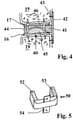
- FIG.4 A version with elastic movement limiters is in Fig.4 and 5 shown.
- an intervertebral disc prosthesis 40 is shown with a buffer or damper 41 which protrudes on one side of the prosthesis 40 between the artificial vertebral end plates 16,17 and is held by an elastic band 42 which is fastened to the vertebral bodies 19 by means of screws 43.
- a tension and/or compression spring 44 is shown as a further example.
- dampers 41 or springs 44 with the same or different elastic properties are used on both sides. It is of course also possible to use different means of limitation, such as in 4 shown to use.
- the elastic band 42 such as a tension belt band, is also included to limit movement and can be fixed to the vertebral bodies 19 on the artificial vertebral end plates 16,17 instead of using the screws 43.
- Dampers 41 and springs 44 located opposite each other on either side of the joint component 45, 46, serve to limit flexion-extension movement or lateral inclinations. In order to limit both directions of movement, such or similar means are also used in the plane transverse to the plane of the drawing, with all or only two opposite. Agents have different properties to the unequal motion limit.
- the springs 44 and elastic band 42 connected to the vertebral endplates 16, 17 also exert tensile forces which are factored into the design of mobility.
- damper 41 when these are connected to the connecting plates 16, 17, for example by gluing, and the tensile force of the band 42 also keep the rotational mobility within limits.
- Springs 44 can also exert a targeted influence on the rotation about the vertical axis by means of the shearing forces.
- the plates 16,17 can also be regarded as artificial vertebral end plates 16,17 separate from the joint prosthesis 45,46, which are attached to the vertebral bodies in such a way that they remain permanently implanted serving as a holder for various components.
- the tension belt can be screwed to the artificial vertebral end plates 16, 17 instead of to the vertebrae.
- the joint parts 45,46 of the prosthesis 40 are also detachably connected to the artificial vertebral end plates 16,17.
- a single damper 50 which at least partially surrounds the articulation point 45,46 of the intervertebral disc prosthesis 40, represents a simple means of limiting movement.
- An example of this is shown in Fig.5 shown, which consists of a U-shaped damper 50 which is inserted from the intervention side between the artificial vertebral end plates 16,17 and screwed to the side edges of the connecting plates 16,17 by means of fastening lugs 54.
- the geometry of the approximately U-shaped damper 50 is adapted to the intervertebral disc prosthesis, for example semi-circular elastic dampers are possible.
- the damper 50 is provided with different characteristics over the length.
- the legs 52 and 53 of the U-shaped damper 50 can be equipped with elastic properties that differ from those of the connecting web 51 or from one another.
- Figures.6a and 6b show an example in side view or in cross section, in which the intervertebral disc prosthesis 60 essentially consists of an elastic cylinder 61 which is connected to the lower plate 62, for example by gluing.
- the upper plate 63 has a sleeve-shaped skirt 64 which surrounds the elastic cylinder 61 in a centering manner.
- the elastic cylinder 61 consists of four sectors 65-68 with different elastic properties, with two opposing sectors 65, 66 having the same properties being provided for the lateral inclinations, for example.
- the two remaining sectors 67, 68 are designed with different elastic characteristics to limit the bending and extension movements in different ways. Many different material pairings with plastics, metal, ceramics or these with each other are also possible.
- a wedge-shaped groove 71 is incorporated parallel to the vertical axis 69 in opposite sectors 65,66, into which a wedge-shaped nose 72 protrudes on the inside of the apron with a corresponding amount of play.
- any other shape can be chosen, e.g. groove and nose with a square cross-section.
- the example according to 6 can be varied such that, for example, the upper plate 63 is anchored to the vertebral body with the apron 64 forming a structural unit as an artificial vertebral end plate 63, 64 and serves as a holder.
- a flat vertebral end plate 74 shown in dashed lines, is also permanently anchored to the opposite vertebral body.
- the prosthesis component 61 , 62 is placed between the two vertebral end plates 63 , 74 and is detachably connected to the lower artificial vertebral end plate 74 .
- inclined bores 73 are provided in the plate-shaped prosthesis component 74 and screw bores (not shown in the drawing) are provided in the artificial vertebral end plate 74 for a screw connection.
- the artificial vertebral end plates 63, 64 and 74 serving as holders can accommodate further elements, for example for limiting movement, which are also attached in a detachable manner.
- the rotation about the vertical axis 69 can also be limited, for example, by elastic bands which are correspondingly screwed onto the two artificial vertebral end plates 63, 64 and 74.
- the grooves 71 and lugs 72 are omitted.
Description
Die Erfindung bezieht sich auf eine Bandscheibenprothese bestehend aus gelenkigen Prothesenkomponenten und Mitteln, die die Beweglichkeit begrenzen, wobei die Begrenzungsmittel derart ausgebildet sind, dass sie die Beuge-Extensionsbewegung und/ oder die Seitenneigung (13) und/oder die Rotation um die Hochachse asymmetrisch begrenzen.The invention relates to an intervertebral disc prosthesis consisting of articulated prosthesis components and means that limit the mobility, the limiting means being designed in such a way that they asymmetrically limit the flexion-extension movement and/or the lateral inclination (13) and/or the rotation about the vertical axis .
Es sind Bandscheibenprothesen bekannt, bei denen Prothesenkomponenten Bewegungen in mehreren Richtungen erlauben, so daß ein Patient, der eine oder mehrere Prothesen dieser Art als Bandscheibenersatz trägt, seine ursprüngliche Bewegungsfreiheit weitgehend beibehalten kann.Intervertebral disc prostheses are known in which the prosthesis components allow movements in several directions, so that a patient who wears one or more prostheses of this type as a replacement intervertebral disc can largely retain his or her original freedom of movement.
Gemäß
Um die Bewegungsfreiheitsgrade einer natürlichen Bandscheide zu imitieren wird gemäß
Aus
Mittel zur Begrenzung der Beweglichkeit in verschiedenen Ebenen sind aus der
Die Beweglichkeit des Implantats wird für den individuellen Patienten angepasst in jeder Bewegungsrichtung gezielt begrenzt, d.h. die Beuge-Extensionsbewegung und/oder die Seitenneigung und/oder die Rotation um die Hochachse werden symmetrisch, wo möglich bzw. nötig auch asymmetrisch begrenzt. Es können damit auch Bewegungsfehlstellungen besser korrigiert werden.The mobility of the implant is specifically limited for the individual patient in each direction of movement, i.e. the flexion-extension movement and/or the lateral inclination and/or the rotation around the vertical axis are limited symmetrically, where possible or necessary also asymmetrically. It can also be better corrected movement misalignments.
Die Verwendung von elastischen Dämpfern ist auch aus der
Der Erfindung liegt die Aufgabe zugrunde, Prothesen mit Bewegungsbegrenzungsmittel zu verbessern. Die Aufgabe wird durch die Merkmale des Anspruchs 1 gelöst.The object of the invention is to improve prostheses with movement-limiting means. The object is solved by the features of claim 1.
Zur Durchführung der erfindungsgemäßen Prothese eignen sich die fertigungstechnisch einfachen Bandscheibenprothesen mit Kugel-Pfannensystem, die dreidimensional beweglich, d.h. dreh- und schwenkbar sind. Gezielt werden Begrenzungsmittel zur gleichen oder ungleichen Begrenzung der Beuge- und Extensionsbewegung einerseits und Seitenneigung in beide Richtungen andererseits verwendet. Die Fixierung der Dämpfer erfolgt an den Wirbelkörpern oder an künstlichen Wirbelendplatten bzw. Appositionsplatten.Intervertebral disc prostheses with a ball and socket system that are simple in terms of manufacturing technology and are three-dimensionally movable, ie rotatable and pivotable, are suitable for carrying out the prosthesis according to the invention. Limiting means are used specifically for the same or unequal limitation of the flexion and extension movement on the one hand and lateral inclination in both directions on the other. The dampers are fixed to the vertebral bodies or to artificial vertebral end plates or apposition plates.
Gemäß einer bevorzugten Ausgestaltung werden die künstlichen Wirbelendplatten getrennt von der Prothese mit den Wirbelkörpern derart verbunden, dass sie auf Dauer verankert bleiben und als Halterung für die Prothese und Bewegungsbegrenzungsmittel dienen. Dieses hat den Vorteil, dass ein notwendiger Austausch der Prothese und/oder eines oder mehrerer Bewegungsbegrenzungsmittel nur eine mechanische Lösung und wieder Anbindung an die künstlichen Wirbelendplatten und nicht am Knochen bedeutet. Damit wird der Operationsvorgang erleichtert und beschleunigt sowie die Knochensubstanz geschont.According to a preferred embodiment, the artificial vertebral end plates are connected to the vertebral bodies separately from the prosthesis in such a way that they remain permanently anchored and serve as a holder for the prosthesis and movement-limiting means. This has the advantage that a necessary replacement of the prosthesis and/or one or more movement limiting means only means a mechanical release and reconnection to the artificial vertebral end plates and not to the bone. This facilitates and accelerates the surgical procedure and protects the bone substance.
Eine einseitige Verbindung der Dämpfer, z.B. an nur einer künstlichen Wirbelendplatte oder einem Wirbelkörper bewirkt, dass diese Dämpfer keinen Einfluß auf die Rotationsbewegung um die Hochachse haben, so dass deren Begrenzung unabhängig von der Beugebewegung ebenfalls gezielt gewählt werden kann. Hierfür könnten beispielsweise Zuggurtungsbänder unterschiedlicher Stärken verwendet werden, die über Kreuz an beiden künstlichen Wirbelendplatten oder Wirbelkörpern fixiert die Rotation um die Hochachse nach rechts und links asymmetrisch Begrenzt oder mit unterschiedlichen Rückstellkräften belegen.A one-sided connection of the dampers, e.g. to only one artificial vertebral end plate or a vertebral body, means that these dampers have no influence on the rotational movement around the vertical axis, so that their limitation can also be specifically selected independently of the flexion movement. For this purpose, for example, tension straps of different strengths could be used, which are fixed crosswise to both artificial vertebral end plates or vertebral bodies, asymmetrically limiting the rotation around the vertical axis to the right and left or subject to different restoring forces.
Eine einfache Ausführung mit elastischen Elementen besteht erfindungsgemäß in einem U-förmigen Dämpfer mit über die Länge unterschiedlichen elastischen Eigenschaften, der nach der Implantation der Prothese seitlich zwischen die Wirbelkörper eingeschoben und an Prothesenkomponenten, an künstliche Wirbelendplatten oder den betroffenen Wirbelkörpern fixiert wird.According to the invention, a simple embodiment with elastic elements consists of a U-shaped damper with elastic properties that vary over the length, which is inserted laterally between the vertebral bodies after implantation of the prosthesis and fixed to prosthesis components, to artificial vertebral end plates or to the affected vertebral bodies.
Die Bewegungsbegrenzenden Mittel können gemäß einer weiteren Ausgestaltung der Erfindung durch entsprechende Formgebungen der relativ zueinander beweglichen Prothesenkomponenten erreicht werden. Am Beispiel des Halbkugel-Pfannesystems lässt sich diese Lösung durch asymmetrische Formengebungen der Halbkugel und/oder Pfanne erreichen.According to a further embodiment of the invention, the movement-limiting means can be achieved by appropriate shaping of the prosthesis components that are movable relative to one another. Using the hemisphere socket system as an example, this solution can be achieved by asymmetrically shaping the hemisphere and/or socket.
Die Bewegungsbegrenzende Funktion kann auch zumindest teilweise durch elastische Bänder, wie Zuggurtungsbänder übernommen werden, die den Bandscheibenbereich überbrücken und unterschiedliche Zugkräfte die notwendigen gezielten Bewegungsbegrenzungen hervorrufen. Die Bänder werden je nach Prothesenausführung entweder an Prothesenteilen, an künstlichen Wirbelendplatten oder an beiden angrenzenden oder weiteren Wirbelkörpern befestigt.The movement-limiting function can also be taken over, at least in part, by elastic straps, such as tension straps, which bridge the area of the intervertebral disks and cause different tensile forces to cause the necessary, targeted movement limitations. Depending on the design of the prosthesis, the ligaments are attached either to prosthesis parts, to artificial vertebral end plates or to both adjacent vertebral bodies or to other vertebral bodies.
Das elastische Band kann vorzugsweise einen Dämpfer aufnehmen oder mit einem integrierten Dämpfer ausgebildet sein, wobei der Dämpfer unbefestigt zwischen z.B. Wirbelendplatten liegt. Damit wird eine Dämpfung auf Druck und auf Zug bewirkt, wobei das Bewegungsbegrenzungssystem wenn nötig, leicht entfernt und ausgetauscht werden kann, indem lediglich die Schraubverbindung des elastischen Bandes gelöst wird.The elastic band may preferably accommodate a damper or be formed with an integral damper, the damper lying unattached between, for example, vertebral endplates. In order to compression and traction damping is effected, the movement limitation system being easily removable and replaceable if necessary, simply by unscrewing the elastic band's screw connection.
Weitere Ausführungsmöglichkeiten bestehen in der Verwendung von elastischen Federn mit unterschiedlichen Federcharakteristiken.Further design options consist in the use of elastic springs with different spring characteristics.
Die Anwendung der erfindungsgemäßen Maßnahmen beschränkt sich nicht auf Kugel-Pfannen Bandscheibenprothesen. Sie sind auf alle gelenkigen Bandscheibenprothesen anwendbar. So kann beispielweise eine Bandscheibenprothese direkt aus einem elastischen Material bestehen, das richtungsabhängig unterschiedliche elastische Eigenschaften hat, zwischen zwei Wirbelendplatten angeordnet ist und durch mindestens eine mit einer Wirbelendplatte verbundene Umrandung bzw. Schürze in der erforderlichen Lage löse gehalten wird. Das elastische Material kann aber auch mit einer Wirbelendplatte z.B. durch Verklebung verbunden sein, während die zweite Wirbelendplatte eine Umrandung oder Schürze aufweist.The application of the measures according to the invention is not limited to ball and socket intervertebral disc prostheses. They are applicable to all articulated disc prostheses. For example, an intervertebral disc prosthesis can consist directly of an elastic material that has different elastic properties depending on the direction, is arranged between two vertebral end plates and is loosely held in the required position by at least one border or apron connected to a vertebral end plate. However, the elastic material can also be connected to one vertebral endplate, e.g. by gluing, while the second vertebral endplate has a border or apron.
Um die individuelle Wirkung für den jeweiligen Patienten zu erreichen, kann gemäß einer weiteren Ausführung der Erfindung eine Kombination von vorstehend beschriebenen Bewegungsbegrenzungsmittel eingesetzt werden.In order to achieve the individual effect for the respective patient, according to a further embodiment of the invention, a combination of movement-limiting means described above can be used.
Eine vorteilhafte Ausgestaltung der Erfindung besteht darin, dass die Bewegungsbegrenzungsmittel lösbar mit Prothesenkomponenten befestigt werden, wodurch in Revisionen die Mittel ohne die Prothese selber entfernen zu müssen leicht ausgetauscht werden können. Derartige eingriffe sind beispielweise notwendig, wenn für den Patienten eine neue Auslegung der einzelnen Bewegungsbegrenzungen erforderlich ist.An advantageous embodiment of the invention consists in the fact that the movement-limiting means are releasably attached to prosthesis components, as a result of which the means can be easily replaced in revisions without having to remove the prosthesis itself. Such interventions are necessary, for example, when a new interpretation of the individual movement limitations is required for the patient.
Eine weitere Ausgestaltung der Erfindung sieht künstliche Wirbelendplatten vor, die auf Dauer jeweils an eines der angrenzenden Wirbelkörper mittels Verklebung, Verschraubung, Krampen, etc. auf Dauer fixiert sind. Die gelenkige Prothesenkomponente und ggf. die Bewegungsbegrenzungsmittel werden lösbar mit den Wirbelendplatten, z.B. durch Verschraubung befestigt. Auf diese Weise reduziert sich eine Nachoperation, bei der die Prothesenkomponente oder Bewegungsbegrenzungsmittel ausgetauscht werden müssen, auf einen mechanischen Wechsel der Elemente. Hier wird also bei einem Revisionseingriff das Prothesenmodul und/oder die Bewegungsbegrenzungsmittel ausgetauscht, während die künstlichen Wirbelendplatten im implantierten Zustand verbleiben. Dadurch wird das Knochenmaterial geschont und der Eingriff bei einer Revision -wird deutlich einfacher und zeitlich verkürzt.A further embodiment of the invention provides artificial vertebral end plates which are permanently fixed to one of the adjoining vertebral bodies by means of gluing, screwing, staples, etc. The articulated prosthesis component and optionally the movement limiting means are detachably attached to the vertebral end plates, for example by screwing. In this way, a follow-up operation, in which the prosthesis component or movement-limiting means have to be exchanged, is reduced to a mechanical exchange of the elements. In this case, the prosthesis module and/or the movement-limiting means are exchanged during a revision operation, while the artificial vertebral end plates remain in the implanted state. This protects the bone material and the intervention during a revision is significantly easier and shorter.
Einen weiteren Vorteil bieten genormte Wirbelendplatten, denen genormte Prothesenmodule unterschiedlicher Auslegung, Gestaltung und Typen zugeordnet werden. So ist ein einfacher Typenaustausch möglich, wenn z.B. bei einem Patienten ein Austausch der ursprünglich eingesetzten gelenkigen Prothesenkomponente durch eine einer anderen Ausgestaltung erforderlich ist.Standardized vertebral end plates, to which standardized prosthesis modules of different design, design and types are assigned, offer a further advantage. This makes it easy to exchange types if, for example, a patient needs to replace the originally used articulated prosthesis component with one of a different design.
Die Erfindung wird anhand von in der Zeichnung schematisch dargestellten Ausführungsbeispielen näher erläutert.The invention is explained in more detail with reference to exemplary embodiments shown schematically in the drawing.
Es zeigen:
-
Fig.1 Eine Dorsalansicht von zwei Wirbelkörpern und einer Bandscheibenprothese mit Halbkugel-Pfannen-Technik im Schnitt, -
Fig.2 Eine Seitenansicht eines Rückgrades mit mehreren Bandscheibenprothesen, -
Fig.3 bis 6b je ein weiteres Ausführungsbeispiel der Erfindung.
-
Fig.1 A dorsal view of two vertebral bodies and a disc prosthesis with hemispherical cup technique in section, -
Fig.2 A side view of a spine with multiple disc prostheses, -
Figures 3 to 6b each another embodiment of the invention.
Um die freie Beweglichkeit der Prothese an die Bedürfnisse des Patienten einzuschränken, werden Maßnahmen ergriffen, die die drei Bewegungsrichtungen 13, 14 und 21 je individuell begrenzen.In order to adapt the free mobility of the prosthesis to the needs of the To restrict patients, measures are taken that limit the three directions of
Gemäß
In ähnlicher Weise können Stufen dieser Art in der Ebene senkrecht zur Zeichnungsebene der
Es ist durchaus bei Patienten möglich, dass die Beweglichkeit eines implantierten Bandscheibenersatzes in Laufe von Jahren verändert werden muss. Es ist deshalb von Vorteil, wenn die Bandscheibenprothese mit Begrenzungsmitteln einen modularen Aufbau hat, bei dem künstliche Wirbelendplatten 16,17 auf Dauer mit den Wirbelkörpern 19 verbunden und die Halbkugel 11 sowie die Pfanne 12 lösbar (nicht in
In der
Eine formgebende asymmetrische Maßnahme für die Begrenzung der Rotationsbewegung 21 ist in
Bewegungsbegrenzungen durch Formschluß sind nicht auf die hier beschriebenen Ausführungen beschränkt. Jede andere Formgebung, Nut und Feder, Vorsprünge, etc., die geeignet sind, die Beweglichkeit einzuschränken, ist Gegenstand dieser Erfindung. Ebenfalls beschränkt sich die Erfindung nicht auf Bandscheibenprothesen in Kugel/Halbkugel-Pfannen Techniken. Die Erfindung lässt sich an diesem Beispiel besonders übersichtlich darstellen.Movement limitations by positive locking are not limited to the embodiments described here. Any other shape, tongue and groove, projections, etc. that are suitable for restricting mobility is the subject of this invention. The invention is also not limited to intervertebral disc prostheses using ball/hemisphere socket techniques. The invention can be illustrated in a particularly clear manner using this example.
Eine Ausführung mit elastischen Bewegungsbegrenzungs-Mitteln sind in
In der Regel werden zu beiden Seiten entweder Dämpfer 41 oder Federn 44 mit gleichen oder unterschiedlichen elastischen Eigenschaften eingesetzt. Es ist natürlich auch möglich, unterschiedliche Begrenzungsmittel, wie z.B. in
Dämpfer 41 und Federn 44, dienen zu beiden Seiten der Gelenckomponente 45,46 gegenüberliegend angeordnet, zur Begrenzung der Beugungs-Extensionsbewegung oder der Seitenneigungen. Um beide Bewegungsrichtungen zu begrenzen werden in der Ebene quer zur Zeichnungsebene ebenfalls derartige oder ähnliche Mittel eingesetzt, wobei alle oder nur zwei gegenüberliegende. Mittel unterschiedliche Eigenschaften zur ungleichen Bewegungsbegrenzung haben. Die mit den Wirbelendplatten 16,17 verbundenen Federn 44 und das elastische Band 42 üben auch Zugkräfte aus, die in die Auslegung der Beweglichkeit einbezogen werden.
Über die Elastizität des Dämpfers 41, wenn diese mit den Verbindungsplatten 16,17 z.B. durch Verklebung verbunden sind, und der Zugkraft des Bandes 42 wird zusätzlich die Rotationsbeweglichkeit in Grenzen gehalten. Federn 44 können durch entsprechende Auslegung über die Scherkräfte auch gezielten Einfluss auf die Rotation um die Hochachse ausüben.The elasticity of the
Die Platten 16,17 können auch als von der Gelenkprothese 45,46 getrennte künstliche Wirbelendplatten 16, 17 angesehen werden, die so an den Wirbelkörpern angebracht sind, dass sie als Halterung für diverse Komponenten dienend auf Dauer implantiert bleiben. Das Zuggurtungsband kann in diesem Fall anstelle am Wirbelknochen an die künstliche Wirbelendplatten 16, 17 angeschraubt werden. Natürlich sind in so einem Fall, die Gelenkteile 45,46 der Prothese 40 ebenfalls lösbar mit den künstlichen Wirbelendplatten 16, 17 verbunden.The
Zweckmäßig ist, wenn die für die Bewegungsbegrenzung getrennte Mittel 41,42,44,50, wie in
Anstelle mehrerer Dämpfer stellt ein einziger Dämpfer 50, der die Gelenkstelle 45,46 der Bandscheibenprothese 40 zumindest teilweise umgibt, ein einfaches Mittel zur Bewegungsbegrenzung dar. Ein Beispiel hierzu ist in
Der elastische Zylinder 61 besteht aus vier Sektoren 65-68 unterschiedlicher elastischer Eigenschaften, wobei beispielsweise für die Seitenneigungen zwei gegenüberliegende eigenschaftsgleiche Sektoren 65,66 vorgesehen sind. Zur unterschiedlichen Begrenzung der Beuge- und Extensionsbewegung sind die beiden übrigen Sektoren 67,68 mit unterschiedlichen elastischen Charakteristiken ausgelegt. Es sind auch viele unterschiedliche Materialpaarungen mit Kunststoffen, Metall, Keramik bzw. diese untereinander möglich.The
Zur Begrenzung der Rotation um die Hochachse 69 sind in gegenüberliegenden Sektoren 65,66 je eine keilförmige Nut 71 parallel zur Hochachse 69 eingearbeitet, in die sich je eine keilförmige Nase 72 an der Schürzeninnenseite mit entsprechendem Spiel hineinragt. Anstelle der Keilform kann jede andere Form gewählt werden, z.B. Nut und Nase mit quadratischem Querschnitt.To limit the rotation about the
Das Beispiel gemäß
Die als Halterungen dienenden künstlichen Wirbelendplatten 63,64 und 74 können weitere Elemente z.B. zur Bewegungsbegrenzung, aufnehmen, die ebenfalls lösbar angebracht werden. Im Beispiel nach
Claims (6)
- Intervertebral disc prosthesis consisting of articulated prosthesis components and means limiting the movability, wherein the limiting means are configured in such a way that they asymmetrically limit the flexion-extension movement and/or the lateral inclination (13) and/or the rotation about the vertical axis, wherein a hemisphere-cup system is provided as an articulated prosthesis component, wherein the movement-limiting means are provided by asymmetric configurations (23, 24) of the hemisphere (11) and/or cup (12) in such a way that the configurations for each direction of movement (14, 15, 21) can be specifically and individually adapted to the patient, characterized in that the hemisphere (11) is formed with a low step (23) and with a higher step (24) which, together with the cup edge, limits the lateral inclination of the intervertebral disc prosthesis.
- Intervertebral disc prosthesis consisting of articulated prosthesis components and means limiting the movability, wherein the limiting means are configured in such a way that they asymmetrically limit the flexion-extension movement and/or the lateral inclination (13) and/or the rotation about the vertical axis, wherein a hemispherecup system is provided as an articulated prosthesis component, wherein the movement-limiting means are provided by asymmetric configurations (23, 24) of the hemisphere (11) and/or cup (12) in such a way that the configurations for each direction of movement (14, 15, 21) can be specifically and individually adapted to the patient, characterized in that the hemisphere (11) is formed with a low step (23) and with a higher step (24) which, together with the cup edge, limits the flexion-extension movement of the intervertebral disc prosthesis.
- Intervertebral disc prosthesis according to claim 1 or 2, characterized in that the steps 23, 24 and/or the cup edges 25, 26 are coated with elastic linings.
- Intervertebral disc prosthesis according to claims 1, 2 or 3, characterized in that at least one elastic band (42) which is attachable to at least two vertebral bodies and exerts tensile forces is provided.
- Intervertebral disc prosthesis according to claim 4, characterized in that the elastic band(s) (42) are provided for receiving and partially fixing intervertebral disc prostheses or parts (41) thereof.
- Intervertebral disc prosthesis according to one of the preceding claims, characterized in that in part tension belts (42) are provided as movement-limiting means.
Applications Claiming Priority (2)
| Application Number | Priority Date | Filing Date | Title |
|---|---|---|---|
| DE102007058304A DE102007058304A1 (en) | 2007-12-04 | 2007-12-04 | Disc prosthesis |
| PCT/DE2008/001829 WO2009071044A1 (en) | 2007-12-04 | 2008-11-06 | Intervertebral disk prosthesis |
Publications (2)
| Publication Number | Publication Date |
|---|---|
| EP2257246A1 EP2257246A1 (en) | 2010-12-08 |
| EP2257246B1 true EP2257246B1 (en) | 2022-01-19 |
Family
ID=40580847
Family Applications (1)
| Application Number | Title | Priority Date | Filing Date |
|---|---|---|---|
| EP08857733.3A Active EP2257246B1 (en) | 2007-12-04 | 2008-11-06 | Intervertebral disk prosthesis |
Country Status (4)
| Country | Link |
|---|---|
| US (1) | US8764834B2 (en) |
| EP (1) | EP2257246B1 (en) |
| DE (1) | DE102007058304A1 (en) |
| WO (1) | WO2009071044A1 (en) |
Families Citing this family (8)
| Publication number | Priority date | Publication date | Assignee | Title |
|---|---|---|---|---|
| EP1978897B1 (en) * | 2006-02-01 | 2013-05-01 | Synthes GmbH | Total disc replacement device |
| US8956412B2 (en) * | 2007-06-22 | 2015-02-17 | Axiomed, LLC | Artificial disc |
| US8083796B1 (en) | 2008-02-29 | 2011-12-27 | Nuvasive, Inc. | Implants and methods for spinal fusion |
| DE102008048739A1 (en) * | 2008-09-24 | 2010-04-01 | Franz Dr. Copf jun. | Disc prosthesis |
| US8496713B2 (en) | 2010-12-10 | 2013-07-30 | Globus Medical, Inc. | Spine stabilization device and methods |
| US8998991B2 (en) * | 2011-02-23 | 2015-04-07 | Globus Medical, Inc. | Six degree spine stabilization devices and methods |
| CN108158786A (en) * | 2017-12-26 | 2018-06-15 | 浙江大学 | A kind of multiple limiting device of Three Degree Of Freedom ectoskeleton hip joint |
| CN113208785B (en) * | 2021-06-10 | 2022-04-19 | 北京爱康宜诚医疗器材有限公司 | Vertebral body prosthesis |
Family Cites Families (24)
| Publication number | Priority date | Publication date | Assignee | Title |
|---|---|---|---|---|
| FR2659226B1 (en) * | 1990-03-07 | 1992-05-29 | Jbs Sa | PROSTHESIS FOR INTERVERTEBRAL DISCS AND ITS IMPLEMENTATION INSTRUMENTS. |
| US5258031A (en) * | 1992-01-06 | 1993-11-02 | Danek Medical | Intervertebral disk arthroplasty |
| DE4208116C2 (en) | 1992-03-13 | 1995-08-03 | Link Waldemar Gmbh Co | Intervertebral disc prosthesis |
| US6039763A (en) | 1998-10-27 | 2000-03-21 | Disc Replacement Technologies, Inc. | Articulating spinal disc prosthesis |
| US6520996B1 (en) * | 1999-06-04 | 2003-02-18 | Depuy Acromed, Incorporated | Orthopedic implant |
| US8388684B2 (en) | 2002-05-23 | 2013-03-05 | Pioneer Signal Technology, Inc. | Artificial disc device |
| US7597713B2 (en) | 2002-09-02 | 2009-10-06 | Synthes Usa, Llc | Intervertebral implant comprising a three-part articulation |
| JP4210653B2 (en) | 2002-12-17 | 2009-01-21 | ジンテーズ ゲゼルシャフト ミト ベシュレンクテル ハフツング | Intervertebral implant |
| GB0301085D0 (en) * | 2003-01-17 | 2003-02-19 | Krishna Manoj | Articulating spinal disc prosthesis |
| US7364589B2 (en) | 2003-02-12 | 2008-04-29 | Warsaw Orthopedic, Inc. | Mobile bearing articulating disc |
| US20050143824A1 (en) | 2003-05-06 | 2005-06-30 | Marc Richelsoph | Artificial intervertebral disc |
| US20090076614A1 (en) * | 2007-09-17 | 2009-03-19 | Spinalmotion, Inc. | Intervertebral Prosthetic Disc with Shock Absorption Core |
| US6871289B2 (en) | 2003-07-08 | 2005-03-22 | Arques Technology | Slew rate limited reference for a buck converter |
| US20050015150A1 (en) * | 2003-07-17 | 2005-01-20 | Lee Casey K. | Intervertebral disk and nucleus prosthesis |
| US7621956B2 (en) * | 2003-07-31 | 2009-11-24 | Globus Medical, Inc. | Prosthetic spinal disc replacement |
| DE20313183U1 (en) * | 2003-08-22 | 2003-10-16 | Aesculap Ag & Co Kg | Intervertebral implant |
| DE20315611U1 (en) | 2003-10-08 | 2003-12-11 | Aesculap Ag & Co. Kg | Intervertebral implant |
| DE10361772B4 (en) | 2003-12-31 | 2006-10-12 | Henning Kloss | Intervertebral disc implant |
| US7250060B2 (en) * | 2004-01-27 | 2007-07-31 | Sdgi Holdings, Inc. | Hybrid intervertebral disc system |
| FR2877833B1 (en) | 2004-11-15 | 2007-10-12 | Alain Ventimiglia | CORRECTEUR OF LORDOSES |
| US20060293752A1 (en) * | 2005-06-27 | 2006-12-28 | Missoum Moumene | Intervertebral disc prosthesis and associated methods |
| US20070225810A1 (en) * | 2006-03-23 | 2007-09-27 | Dennis Colleran | Flexible cage spinal implant |
| US20080161928A1 (en) * | 2006-12-27 | 2008-07-03 | Warsaw Orthopedic, Inc. | Compliant intervertebral prosthetic devices with motion constraining tethers |
| CA2677805C (en) * | 2007-02-09 | 2013-09-10 | Diamicron, Inc. | Multi-lobe artificial spine joint |
-
2007
- 2007-12-04 DE DE102007058304A patent/DE102007058304A1/en active Pending
-
2008
- 2008-11-06 US US12/741,353 patent/US8764834B2/en active Active
- 2008-11-06 EP EP08857733.3A patent/EP2257246B1/en active Active
- 2008-11-06 WO PCT/DE2008/001829 patent/WO2009071044A1/en active Application Filing
Also Published As
| Publication number | Publication date |
|---|---|
| EP2257246A1 (en) | 2010-12-08 |
| DE102007058304A1 (en) | 2009-06-10 |
| US20100249936A1 (en) | 2010-09-30 |
| US8764834B2 (en) | 2014-07-01 |
| WO2009071044A1 (en) | 2009-06-11 |
Similar Documents
| Publication | Publication Date | Title |
|---|---|---|
| EP2257246B1 (en) | Intervertebral disk prosthesis | |
| DE69917634T2 (en) | ARTIFICIAL BRAKE PRAYER | |
| EP1804735B1 (en) | Intervertebral disc endoprosthesis with a motion-adapted edge for the lumbar vertebral column and cervical vertebral column | |
| DE69434929T2 (en) | Arthroplastic device for intervertebral discs | |
| DE69836834T2 (en) | TRANSLATION AND ROTATION MOVEMENT PERMISSIBLE ARTIFICIAL INTERMEDIATE JOINTING | |
| EP1572039B1 (en) | Intervertebral implant | |
| EP1729690B1 (en) | Modular intervertebral implant or intervertebral disc prosthesis | |
| DE60107818T2 (en) | BELT PANTHEES FOR HALSWIRBELSÄULE | |
| DE10347172B4 (en) | Intervertebral implant | |
| DE60302595T2 (en) | Swivel adapter with swiveling end plates | |
| DE69733850T2 (en) | Intervertebral prosthetic device | |
| EP1804736B1 (en) | Intervertebral disc endoprosthesis having cylindrical articulation surfaces that are curved in a transversally arched manner for the lumbar vertebral column and cervical vertebral column | |
| EP1816989B8 (en) | Physiological intervertebral disk endoprosthesis for the lumbar column and cervical vertebral column | |
| DE10323363A1 (en) | Implant for insertion between elements of the vertebral column comprises a hinge which consist of a socket plate and a head element, and is located between the hinge cover plates | |
| EP1250898A1 (en) | Intervertebral disc prosthesis system | |
| CH624573A5 (en) | Intervertebral prosthesis | |
| DE602005003242T2 (en) | Intervertebral prosthesis | |
| EP1848379A1 (en) | Intervertebral implant | |
| DE10130825A1 (en) | Inter articular disk prosthesis, comprises a spiral which is made of a metal with memory, and has spherical ends extending into the prosthesis coupling knobs | |
| EP1610730A1 (en) | Prosthetic joint of cervical intervertebral for a cervical spine | |
| EP1967166A1 (en) | Intervertebral prosthesis | |
| EP2339993B1 (en) | Kit for constructing a spinal disk prosthesis, and system for constructing different spinal disk prostheses | |
| WO2006042484A1 (en) | Bent sliding core as part of an intervertebral disk endoprosthesis | |
| DE102007042946B4 (en) | Implantable, prosthetic vertebral body replacement | |
| WO2009071045A1 (en) | Modular prostheses and method for implanting modular prostheses |
Legal Events
| Date | Code | Title | Description |
|---|---|---|---|
| PUAI | Public reference made under article 153(3) epc to a published international application that has entered the european phase |
Free format text: ORIGINAL CODE: 0009012 |
|
| 17P | Request for examination filed |
Effective date: 20100923 |
|
| AK | Designated contracting states |
Kind code of ref document: A1 Designated state(s): AT BE BG CH CY CZ DE DK EE ES FI FR GB GR HR HU IE IS IT LI LT LU LV MC MT NL NO PL PT RO SE SI SK TR |
|
| AX | Request for extension of the european patent |
Extension state: AL BA MK RS |
|
| DAX | Request for extension of the european patent (deleted) | ||
| 17Q | First examination report despatched |
Effective date: 20140516 |
|
| STAA | Information on the status of an ep patent application or granted ep patent |
Free format text: STATUS: EXAMINATION IS IN PROGRESS |
|
| STAA | Information on the status of an ep patent application or granted ep patent |
Free format text: STATUS: EXAMINATION IS IN PROGRESS |
|
| GRAP | Despatch of communication of intention to grant a patent |
Free format text: ORIGINAL CODE: EPIDOSNIGR1 |
|
| STAA | Information on the status of an ep patent application or granted ep patent |
Free format text: STATUS: GRANT OF PATENT IS INTENDED |
|
| INTG | Intention to grant announced |
Effective date: 20210812 |
|
| GRAS | Grant fee paid |
Free format text: ORIGINAL CODE: EPIDOSNIGR3 |
|
| STAA | Information on the status of an ep patent application or granted ep patent |
Free format text: STATUS: GRANT OF PATENT IS INTENDED |
|
| GRAA | (expected) grant |
Free format text: ORIGINAL CODE: 0009210 |
|
| STAA | Information on the status of an ep patent application or granted ep patent |
Free format text: STATUS: THE PATENT HAS BEEN GRANTED |
|
| AK | Designated contracting states |
Kind code of ref document: B1 Designated state(s): AT BE BG CH CY CZ DE DK EE ES FI FR GB GR HR HU IE IS IT LI LT LU LV MC MT NL NO PL PT RO SE SI SK TR |
|
| REG | Reference to a national code |
Ref country code: GB Ref legal event code: FG4D Free format text: NOT ENGLISH |
|
| REG | Reference to a national code |
Ref country code: CH Ref legal event code: EP |
|
| REG | Reference to a national code |
Ref country code: DE Ref legal event code: R096 Ref document number: 502008017240 Country of ref document: DE |
|
| REG | Reference to a national code |
Ref country code: AT Ref legal event code: REF Ref document number: 1463354 Country of ref document: AT Kind code of ref document: T Effective date: 20220215 |
|
| REG | Reference to a national code |
Ref country code: IE Ref legal event code: FG4D Free format text: LANGUAGE OF EP DOCUMENT: GERMAN |
|
| REG | Reference to a national code |
Ref country code: LT Ref legal event code: MG9D |
|
| REG | Reference to a national code |
Ref country code: NL Ref legal event code: MP Effective date: 20220119 |
|
| PG25 | Lapsed in a contracting state [announced via postgrant information from national office to epo] |
Ref country code: NL Free format text: LAPSE BECAUSE OF FAILURE TO SUBMIT A TRANSLATION OF THE DESCRIPTION OR TO PAY THE FEE WITHIN THE PRESCRIBED TIME-LIMIT Effective date: 20220119 |
|
| PG25 | Lapsed in a contracting state [announced via postgrant information from national office to epo] |
Ref country code: SE Free format text: LAPSE BECAUSE OF FAILURE TO SUBMIT A TRANSLATION OF THE DESCRIPTION OR TO PAY THE FEE WITHIN THE PRESCRIBED TIME-LIMIT Effective date: 20220119 Ref country code: PT Free format text: LAPSE BECAUSE OF FAILURE TO SUBMIT A TRANSLATION OF THE DESCRIPTION OR TO PAY THE FEE WITHIN THE PRESCRIBED TIME-LIMIT Effective date: 20220519 Ref country code: NO Free format text: LAPSE BECAUSE OF FAILURE TO SUBMIT A TRANSLATION OF THE DESCRIPTION OR TO PAY THE FEE WITHIN THE PRESCRIBED TIME-LIMIT Effective date: 20220419 Ref country code: LT Free format text: LAPSE BECAUSE OF FAILURE TO SUBMIT A TRANSLATION OF THE DESCRIPTION OR TO PAY THE FEE WITHIN THE PRESCRIBED TIME-LIMIT Effective date: 20220119 Ref country code: HR Free format text: LAPSE BECAUSE OF FAILURE TO SUBMIT A TRANSLATION OF THE DESCRIPTION OR TO PAY THE FEE WITHIN THE PRESCRIBED TIME-LIMIT Effective date: 20220119 Ref country code: ES Free format text: LAPSE BECAUSE OF FAILURE TO SUBMIT A TRANSLATION OF THE DESCRIPTION OR TO PAY THE FEE WITHIN THE PRESCRIBED TIME-LIMIT Effective date: 20220119 Ref country code: BG Free format text: LAPSE BECAUSE OF FAILURE TO SUBMIT A TRANSLATION OF THE DESCRIPTION OR TO PAY THE FEE WITHIN THE PRESCRIBED TIME-LIMIT Effective date: 20220419 |
|
| PG25 | Lapsed in a contracting state [announced via postgrant information from national office to epo] |
Ref country code: PL Free format text: LAPSE BECAUSE OF FAILURE TO SUBMIT A TRANSLATION OF THE DESCRIPTION OR TO PAY THE FEE WITHIN THE PRESCRIBED TIME-LIMIT Effective date: 20220119 Ref country code: LV Free format text: LAPSE BECAUSE OF FAILURE TO SUBMIT A TRANSLATION OF THE DESCRIPTION OR TO PAY THE FEE WITHIN THE PRESCRIBED TIME-LIMIT Effective date: 20220119 Ref country code: GR Free format text: LAPSE BECAUSE OF FAILURE TO SUBMIT A TRANSLATION OF THE DESCRIPTION OR TO PAY THE FEE WITHIN THE PRESCRIBED TIME-LIMIT Effective date: 20220420 Ref country code: FI Free format text: LAPSE BECAUSE OF FAILURE TO SUBMIT A TRANSLATION OF THE DESCRIPTION OR TO PAY THE FEE WITHIN THE PRESCRIBED TIME-LIMIT Effective date: 20220119 |
|
| PG25 | Lapsed in a contracting state [announced via postgrant information from national office to epo] |
Ref country code: IS Free format text: LAPSE BECAUSE OF FAILURE TO SUBMIT A TRANSLATION OF THE DESCRIPTION OR TO PAY THE FEE WITHIN THE PRESCRIBED TIME-LIMIT Effective date: 20220519 |
|
| REG | Reference to a national code |
Ref country code: DE Ref legal event code: R097 Ref document number: 502008017240 Country of ref document: DE |
|
| PG25 | Lapsed in a contracting state [announced via postgrant information from national office to epo] |
Ref country code: SK Free format text: LAPSE BECAUSE OF FAILURE TO SUBMIT A TRANSLATION OF THE DESCRIPTION OR TO PAY THE FEE WITHIN THE PRESCRIBED TIME-LIMIT Effective date: 20220119 Ref country code: RO Free format text: LAPSE BECAUSE OF FAILURE TO SUBMIT A TRANSLATION OF THE DESCRIPTION OR TO PAY THE FEE WITHIN THE PRESCRIBED TIME-LIMIT Effective date: 20220119 Ref country code: EE Free format text: LAPSE BECAUSE OF FAILURE TO SUBMIT A TRANSLATION OF THE DESCRIPTION OR TO PAY THE FEE WITHIN THE PRESCRIBED TIME-LIMIT Effective date: 20220119 Ref country code: DK Free format text: LAPSE BECAUSE OF FAILURE TO SUBMIT A TRANSLATION OF THE DESCRIPTION OR TO PAY THE FEE WITHIN THE PRESCRIBED TIME-LIMIT Effective date: 20220119 Ref country code: CZ Free format text: LAPSE BECAUSE OF FAILURE TO SUBMIT A TRANSLATION OF THE DESCRIPTION OR TO PAY THE FEE WITHIN THE PRESCRIBED TIME-LIMIT Effective date: 20220119 |
|
| PLBE | No opposition filed within time limit |
Free format text: ORIGINAL CODE: 0009261 |
|
| STAA | Information on the status of an ep patent application or granted ep patent |
Free format text: STATUS: NO OPPOSITION FILED WITHIN TIME LIMIT |
|
| PGFP | Annual fee paid to national office [announced via postgrant information from national office to epo] |
Ref country code: BE Payment date: 20220926 Year of fee payment: 15 |
|
| 26N | No opposition filed |
Effective date: 20221020 |
|
| PG25 | Lapsed in a contracting state [announced via postgrant information from national office to epo] |
Ref country code: SI Free format text: LAPSE BECAUSE OF FAILURE TO SUBMIT A TRANSLATION OF THE DESCRIPTION OR TO PAY THE FEE WITHIN THE PRESCRIBED TIME-LIMIT Effective date: 20220119 |
|
| PG25 | Lapsed in a contracting state [announced via postgrant information from national office to epo] |
Ref country code: MC Free format text: LAPSE BECAUSE OF FAILURE TO SUBMIT A TRANSLATION OF THE DESCRIPTION OR TO PAY THE FEE WITHIN THE PRESCRIBED TIME-LIMIT Effective date: 20220119 |
|
| PG25 | Lapsed in a contracting state [announced via postgrant information from national office to epo] |
Ref country code: IT Free format text: LAPSE BECAUSE OF FAILURE TO SUBMIT A TRANSLATION OF THE DESCRIPTION OR TO PAY THE FEE WITHIN THE PRESCRIBED TIME-LIMIT Effective date: 20220119 |
|
| PG25 | Lapsed in a contracting state [announced via postgrant information from national office to epo] |
Ref country code: LU Free format text: LAPSE BECAUSE OF NON-PAYMENT OF DUE FEES Effective date: 20221106 |
|
| PG25 | Lapsed in a contracting state [announced via postgrant information from national office to epo] |
Ref country code: IE Free format text: LAPSE BECAUSE OF NON-PAYMENT OF DUE FEES Effective date: 20221106 |
|
| PGFP | Annual fee paid to national office [announced via postgrant information from national office to epo] |
Ref country code: GB Payment date: 20231009 Year of fee payment: 16 |
|
| PGFP | Annual fee paid to national office [announced via postgrant information from national office to epo] |
Ref country code: FR Payment date: 20231013 Year of fee payment: 16 Ref country code: DE Payment date: 20231026 Year of fee payment: 16 Ref country code: CH Payment date: 20231202 Year of fee payment: 16 Ref country code: AT Payment date: 20231027 Year of fee payment: 16 |
|
| PGFP | Annual fee paid to national office [announced via postgrant information from national office to epo] |
Ref country code: BE Payment date: 20231027 Year of fee payment: 16 |
|
| PG25 | Lapsed in a contracting state [announced via postgrant information from national office to epo] |
Ref country code: HU Free format text: LAPSE BECAUSE OF FAILURE TO SUBMIT A TRANSLATION OF THE DESCRIPTION OR TO PAY THE FEE WITHIN THE PRESCRIBED TIME-LIMIT; INVALID AB INITIO Effective date: 20081106 |