EP2257036A1 - Portable electronic apparatus capable of operating as a wireless communication product and method thereof - Google Patents
Portable electronic apparatus capable of operating as a wireless communication product and method thereof Download PDFInfo
- Publication number
- EP2257036A1 EP2257036A1 EP09011679A EP09011679A EP2257036A1 EP 2257036 A1 EP2257036 A1 EP 2257036A1 EP 09011679 A EP09011679 A EP 09011679A EP 09011679 A EP09011679 A EP 09011679A EP 2257036 A1 EP2257036 A1 EP 2257036A1
- Authority
- EP
- European Patent Office
- Prior art keywords
- designated device
- wireless communication
- portable electronic
- electronic apparatus
- data access
- Prior art date
- Legal status (The legal status is an assumption and is not a legal conclusion. Google has not performed a legal analysis and makes no representation as to the accuracy of the status listed.)
- Granted
Links
- 238000004891 communication Methods 0.000 title claims abstract description 78
- 238000000034 method Methods 0.000 title claims description 26
- 230000005540 biological transmission Effects 0.000 claims abstract description 46
- 230000006870 function Effects 0.000 description 67
- 238000010586 diagram Methods 0.000 description 6
- 238000012986 modification Methods 0.000 description 3
- 230000004048 modification Effects 0.000 description 3
- 230000008569 process Effects 0.000 description 3
- 238000010295 mobile communication Methods 0.000 description 2
- 230000004075 alteration Effects 0.000 description 1
- 238000006243 chemical reaction Methods 0.000 description 1
- 238000005516 engineering process Methods 0.000 description 1
- 238000004088 simulation Methods 0.000 description 1
- 230000001360 synchronised effect Effects 0.000 description 1
Images


Classifications
-
- H—ELECTRICITY
- H04—ELECTRIC COMMUNICATION TECHNIQUE
- H04W—WIRELESS COMMUNICATION NETWORKS
- H04W52/00—Power management, e.g. TPC [Transmission Power Control], power saving or power classes
- H04W52/02—Power saving arrangements
- H04W52/0209—Power saving arrangements in terminal devices
- H04W52/0261—Power saving arrangements in terminal devices managing power supply demand, e.g. depending on battery level
- H04W52/0274—Power saving arrangements in terminal devices managing power supply demand, e.g. depending on battery level by switching on or off the equipment or parts thereof
- H04W52/028—Power saving arrangements in terminal devices managing power supply demand, e.g. depending on battery level by switching on or off the equipment or parts thereof switching on or off only a part of the equipment circuit blocks
-
- H—ELECTRICITY
- H04—ELECTRIC COMMUNICATION TECHNIQUE
- H04M—TELEPHONIC COMMUNICATION
- H04M1/00—Substation equipment, e.g. for use by subscribers
- H04M1/72—Mobile telephones; Cordless telephones, i.e. devices for establishing wireless links to base stations without route selection
- H04M1/724—User interfaces specially adapted for cordless or mobile telephones
- H04M1/72403—User interfaces specially adapted for cordless or mobile telephones with means for local support of applications that increase the functionality
- H04M1/72409—User interfaces specially adapted for cordless or mobile telephones with means for local support of applications that increase the functionality by interfacing with external accessories
- H04M1/72412—User interfaces specially adapted for cordless or mobile telephones with means for local support of applications that increase the functionality by interfacing with external accessories using two-way short-range wireless interfaces
-
- Y—GENERAL TAGGING OF NEW TECHNOLOGICAL DEVELOPMENTS; GENERAL TAGGING OF CROSS-SECTIONAL TECHNOLOGIES SPANNING OVER SEVERAL SECTIONS OF THE IPC; TECHNICAL SUBJECTS COVERED BY FORMER USPC CROSS-REFERENCE ART COLLECTIONS [XRACs] AND DIGESTS
- Y02—TECHNOLOGIES OR APPLICATIONS FOR MITIGATION OR ADAPTATION AGAINST CLIMATE CHANGE
- Y02D—CLIMATE CHANGE MITIGATION TECHNOLOGIES IN INFORMATION AND COMMUNICATION TECHNOLOGIES [ICT], I.E. INFORMATION AND COMMUNICATION TECHNOLOGIES AIMING AT THE REDUCTION OF THEIR OWN ENERGY USE
- Y02D30/00—Reducing energy consumption in communication networks
- Y02D30/70—Reducing energy consumption in communication networks in wireless communication networks
Definitions
- the present invention relates to a portable electronic apparatus (e.g. a mobile phone) capable of simulating as a wireless communication product (e. g. a wireless LAN card) and method thereof, and more particularly, to a portable electronic apparatus is able to directly use a wireless communication function (e.g. wireless Internet access) offered by the portable electronic apparatus without processes of its CPU and method thereof.
- a portable electronic apparatus e.g. a mobile phone
- a wireless communication product e. g. a wireless LAN card
- a portable electronic apparatus is able to directly use a wireless communication function (e.g. wireless Internet access) offered by the portable electronic apparatus without processes of its CPU and method thereof.
- a wireless communication function e.g. wireless Internet access
- equipments such as a notebook computer or a desktop computer are able to connect to a mobile phone to access wireless Internet via a connection interface, such as universal serial bus (USB), infrared rays (IR), or blue-tooth.
- USB universal serial bus
- IR infrared rays
- blue-tooth a connection interface
- USB universal serial bus
- IR infrared rays
- blue-tooth a connection interface
- USB universal serial bus
- IR infrared rays
- blue-tooth blue-tooth
- a portable electronic apparatus capable of simulating as a wireless communication product.
- the portable electronic apparatus consists of a wireless module, a micro processing unit, a determining circuit, and a control circuit.
- the wireless module provides a wireless communication function.
- the micro processing unit consists of a first controller and a second controller.
- the first controller controls operations of the portable electronic apparatus and provides a data access function.
- the second controller controls operations of the wireless module.
- the determining circuit determines whether to use the wireless communication function and whether to use the data access function to generate a determining result.
- the control circuit is coupled to the determining circuit and selects to connect a transmission interface of the first controller or a transmission interface of the wireless module to the designated device according to the determining result.
- the wireless communication product can be a wireless LAN card, and the wireless communication function of the wireless module can be a wireless Internet access function.
- a method for simulating a wireless communication product by utilizing a portable electronic apparatus consists of a wireless module for providing a wireless communication function and a first controller for providing a data access function.
- the method includes the following steps: when a designated device is coupled to the portable electronic apparatus, determining whether the designated device uses the wireless communication function and whether the designated device uses the data access function to generate a determining result; and selecting to connect a transmission interface of the first controller or a transmission interface of the wireless module to the designated device according to the determining result.
- the determining result indicates that the designated device chooses to use the wireless communication function without using the data access function, connect the transmission interface of the wireless module to the designated device.
- FIG.1 is a schematic diagram of the appearance of a portable electronic apparatus capable of simulating as a wireless communication product.
- FIG.2 is a block diagram of the portable electronic apparatus shown in FIG.1 according to a first embodiment of the present invention.
- FIG.3 is a block diagram of the portable electronic apparatus shown in FIG.1 according to a second embodiment of the present invention.
- FIG.4 is flowchart illustrating a method for simulating a wireless communication product by utilizing a portable electronic apparatus according to an exemplary embodiment of the present invention.
- FIG.5 is flowchart illustrating a method for simulating a wireless communication product by utilizing a portable electronic apparatus according to another exemplary embodiment of the present invention.
- FIG.1 is a schematic diagram of the appearance of a portable electronic apparatus 100 capable of simulating as a wireless communication product
- FIG.2 is a block diagram of the portable electronic apparatus 100 shown in FIG.1 according to a first embodiment of the present invention.
- the portable electronic apparatus 100 can be a mobile phone or a personal digital assistant (PDA), but the present invention is not limited to this only and can be portable electronic apparatuses of other types.
- a designated device 200 is coupled to the portable electronic apparatus 100 via a connection interface 210, such as infrared rays (IR), blue-tooth, or USB.
- IR infrared rays
- USB universal adapter
- the designated device 200 can be a notebook computer or a desktop computer, but this should not be considered as limitations of the present invention.
- the designated device 200 can determine whether to use a data access function and/or a wireless communication function offered by the portable electronic apparatus 100 so as to proceed a synchronous data transmission between the portable electronic apparatus 100 or access a wireless Internet via the portable electronic apparatus 100.
- the portable electronic apparatus 100 consists of, but is not limited to, a wireless module 110, a micro processing unit 120, a storage unit 130, a detecting circuit 140, a determining circuit 150, and a control circuit 160.
- the wireless module 110 provides a wireless communication function, such as a wireless Internet access function.
- the micro processing unit 120 consists of a first controller 121 and a second controller 122.
- the first controller 121 controls operations of the portable electronic apparatus 100 and provides a data access function
- the second controller 122 controls operations of the wireless module 110.
- the storage unit 130 (e.g. a memory) is coupled to the first controller 121 and the second controller 122 for providing memory spaces of data access.
- the detecting circuit 140 is coupled to the determining circuit 150, and it detects whether the portable electronic apparatus 100 is coupled to the designated device 200.
- the determining circuit 150 determines whether the designated device 200 uses the wireless communication function and whether the designated device 200 uses the data access function to generate a determining result DR.
- the control circuit 160 is coupled to the determining circuit 150 for selecting to connect a transmission interface of the first controller 121 or a transmission interface of the wireless module 110 to the designated device 200 according to the determining result DR.
- the portable electronic apparatus 100 can be simulated as a wireless communication product.
- the wireless communication product can be a wireless LAN card
- the wireless communication function of the wireless module 110 can be a wireless Internet access function.
- control circuit 160 In a first condition, when the determining result DR of the determining circuit 150 indicates that the designated device 200 chooses to use the wireless communication function without using the data access function, the control circuit 160 connects the transmission interface of the wireless module 110 to the designated device 200. That is, a second path PA2 and the connection interface 210 are connected. In a second condition, when the determining result DR indicates that the designated device 200 chooses to use the data access function without using the wireless communication function, the control circuit 160 connects the transmission interface of the first controller 121 to the designated device 200. That is, a first path PA1 and the connection interface 210 are connected.
- the control circuit 160 connects the transmission interface of the first controller 121 to the designated device 200.
- the first path PA1 and the connection interface 210 are connected.
- the control circuit 160 can control the micro processing unit 120 to enter a power-saving mode (such as a stand-by mode) to save power consumption when the designated device 200 chooses to use the wireless communication function without using the data access function.
- a power-saving mode such as a stand-by mode
- the micro processing unit 120 is required for accessing data from the storage unit 130.
- the micro processing unit 120 is also required for accessing data from the storage unit 130 and for controlling operations of the wireless module 110.
- the designated device 200 must switch different drivers and firmware of the wireless module 110 in order to use the wireless communication function offered by the wireless module 110.
- the control circuit 160 performs a first designated application program AP1 to select the original drivers and firmware of the wireless module 110; and when the designated device chooses to use the wireless communication function without using the data access function (i.e. the connection interface 210 is directly connected to the transmission interface of the wireless module 110), the control circuit 160 performs a second designated application program AP2 to switch the drivers and firmware of the wireless module 110. Therefore, the designated device 200 is able to directly use the wireless communication function (e.g. the wireless Internet access function) offered by the wireless module 110 without processes of the micro processing unit 120.
- the wireless communication function e.g. the wireless Internet access function
- the detecting circuit 140 and the determining circuit 150 are optional elements, and can be omitted or can be replaced by other elements that can achieve the same goal.
- the user can directly select to switch different modes of the portable electronic apparatus 100 so as to determine whether to use the wireless communication function and/or the data access function.
- the determining circuit 150 is replaced by the selection of the user.
- the control circuit 160 can consist of a multiplexer 170, and thus the control circuit 160 can select to connect the transmission interface of the first controller 121 or the transmission interface of the wireless module 110 to the designated device 200 via the multiplexer 170. In other words, the control circuit 160 performs a switching operation upon the first path PA1 and the second path PA2 by using the multiplexer 170.
- This is merely an example for illustrating the present invention, and in no way should be considered to be limitations of the scope of the present invention. Those skilled in the art should appreciate that various modifications of the control circuit 160 may be made without departing from the spirit of the present invention.
- FIG.3 is a block diagram of the portable electronic apparatus shown in FIG. 1 according to a second embodiment of the present invention.
- the architecture of the portable electronic apparatus 300 is similar to that of the portable electronic apparatus 100 shown in FIG.2 , and the difference between them is that a control circuit 360 of the portable electronic apparatus 300 consists of a switch SW1.
- the control circuit 360 can perform a switching operation upon the first path PA1 and the second path PA2 by using the switch SW1 so as to select to connect the transmission interface of the first controller 121 or the transmission interface of the wireless module 110 to the designated device 200.
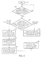
- FIG.4 is flowchart illustrating a method for simulating a wireless communication product by utilizing a portable electronic apparatus according to an exemplary embodiment of the present invention. Please note that the following steps are not limited to be performed according to the exact sequence shown in FIG.4 if a roughly identical result can be obtained.
- the method includes, but is not limited to, the following steps:
- Step 402 Start.
- Step 404 Detect whether the portable electronic apparatus is coupled to the designated device. When the portable electronic apparatus is coupled to the designated device, go to Step 410; otherwise, go back to Step 404.
- Step 410 Determine whether to use the wireless communication function and whether to use the data access function to generate a determining result.
- Step 420 When the determining result indicates that the designated device chooses to use the wireless communication function without using the data access function, go to Step 420; and when the determining result indicates that the designated device chooses to use the data access function without using the wireless communication function, go to Step 430.
- Step 420 Connect the transmission interface of the wireless module to the designated device. After that, go to Step 422.
- Step 422 The portable electronic apparatus is simulated as a wireless communication product. After that, go to Step 424.
- Step 424 Perform a second designated application program to switch the drivers and firmware of the wireless module. After that, go to Step 426.
- Step 426 Control the micro processing unit to enter a power-saving mode.
- Step 430 Connect the transmission interface of the first controller to the designated device.
- the step 404 is executed by the detecting circuit 140
- the step 410 is executed by the determining circuit 150
- the steps 420-430 are executed by the control circuit 160 or 360.
- the control circuit 160/360 can selectively switch paths, i.e. connecting the transmission interface of the first controller 121 or the transmission interface of the wireless module 110 to the designated device 200, depending on whether to use the wireless communication function and whether to use the data access function.
- FIG.5 is flowchart illustrating a method for simulating a wireless communication product by utilizing a portable electronic apparatus according to another exemplary embodiment of the present invention.
- the method includes, but is not limited to, the following steps:
- Step 402 Start.
- Step 404 Detect whether the portable electronic apparatus is coupled to the designated device. When the portable electronic apparatus is coupled to the designated device, go to Step 410; otherwise, go back to Step 404.
- Step 410 Determine whether to use the wireless communication function and whether to use the data access function to generate a determining result.
- Step 420 When the determining result indicates that the designated device chooses to use the wireless communication function without using the data access function, go to Step 420; when the determining result indicates that the designated device chooses to use the data access function without using the wireless communication function, go to Step 430; and when the determining result indicates that the designated device chooses to use the data access function together with the wireless communication function simultaneously, go to Step 510.
- Step 420 Connect the transmission interface of the wireless module to the designated device. After that, go to Step 422.
- Step 422 The portable electronic apparatus is simulated as a wireless communication product. After that, go to Step 424.
- Step 424 Perform a second designated application program to switch the drivers and firmware of the wireless module. After that, go to Step 426.
- Step 426 Control the micro processing unit to enter a power-saving mode.
- Step 430 Connect the transmission interface of the first controller to the designated device.
- Step 510 Connect the transmission interface of the first controller to the designated device. After that, go to Step 512.
- Step 512 Perform a first designated application program to select the original drivers and firmware of the wireless module.
- FIG. 5 Please note that the steps shown in FIG. 5 are similar to the steps shown in FIG.4 , which is a varied embodiment of FIG.4 . The difference between them is that the flowchart shown in FIG.5 further consists of a third condition- a condition that the designated device chooses to use the data access function together with the wireless communication function simultaneously (i.e. the steps 510 and 512). How each element operates can be known by collocating the steps shown in FIG.5 together with the elements shown in FIG.2 or FIG.3 . And further description of the steps shown in FIG.5 is omitted here for brevity. The steps 510 and 512 are executed by the control circuit 160 or 360.
- the present invention provides a portable electronic apparatus (e.g. a mobile phone or a PDA) capable of simulating as a wireless communication product (e. g. a wireless LAN card) and method thereof.
- a portable electronic apparatus e.g. a mobile phone or a PDA
- a wireless communication product e. g. a wireless LAN card
- the control circuit such as a multiplexer or a switch
- the transmission interface of the first controller or the transmission interface of the wireless module can be selectively connected to the designated device (such as a desktop computer or a notebook computer).
- the designated device when the designated device chooses to use the wireless communication function without using the data access function, it is able to directly use wireless communication function (such as a wireless Internet access function) offered by the wireless module without processes of the micro processing unit of the portable electronic apparatus. Therefore, the efficiency of wireless Internet access can be improved so as to approximate to the simulation of the wireless LAN card.
- the micro processing unit can be further controlled to enter a power-saving mode (e.g. a stand-by mode) to save power consumption of the portable electronic apparatus.
Abstract
Description
- The present invention relates to a portable electronic apparatus (e.g. a mobile phone) capable of simulating as a wireless communication product (e. g. a wireless LAN card) and method thereof, and more particularly, to a portable electronic apparatus is able to directly use a wireless communication function (e.g. wireless Internet access) offered by the portable electronic apparatus without processes of its CPU and method thereof.
- With the evolution of mobile communication technology, a utility rate of a mobile communication device is getting higher and higher, and the chance of utilizing a mobile phone to connect to Internet is also increasing. Therefore, in any place with wireless Internet access, a user can enjoy wireless communication services, such as browsing Internet, checking Email, looking parking information up, watching WebTV, etc through a mobile phone at any time.
- At present, equipments such as a notebook computer or a desktop computer are able to connect to a mobile phone to access wireless Internet via a connection interface, such as universal serial bus (USB), infrared rays (IR), or blue-tooth. However, because the data transmission path of connecting the notebook computer to a wireless module of the mobile phone is too long, and the central processing unit as well as operating system of the mobile phone are required for data processing and format conversion, it will slow down the overall processing speed and result in a poor performance. In addition, when the notebook computer accesses wireless Internet through the mobile phone, it must continuously communicate with the components of the mobile phone, such as the central processing unit, memory, and wireless module, and access data between them. Actually, these actions are quite power-consuming.
- It is one of the objectives of the claimed invention to provide a portable electronic apparatus capable of simulating as a wireless communication product and a related method to solve the abovementioned problems.
- According to one embodiment, a portable electronic apparatus capable of simulating as a wireless communication product is provided. The portable electronic apparatus consists of a wireless module, a micro processing unit, a determining circuit, and a control circuit. The wireless module provides a wireless communication function. The micro processing unit consists of a first controller and a second controller. The first controller controls operations of the portable electronic apparatus and provides a data access function. The second controller controls operations of the wireless module. When a designated device is coupled to the portable electronic apparatus, the determining circuit determines whether to use the wireless communication function and whether to use the data access function to generate a determining result. The control circuit is coupled to the determining circuit and selects to connect a transmission interface of the first controller or a transmission interface of the wireless module to the designated device according to the determining result. The wireless communication product can be a wireless LAN card, and the wireless communication function of the wireless module can be a wireless Internet access function.
- According to another embodiment, a method for simulating a wireless communication product by utilizing a portable electronic apparatus is provided. The portable electronic apparatus consists of a wireless module for providing a wireless communication function and a first controller for providing a data access function.
The method includes the following steps: when a designated device is coupled to the portable electronic apparatus, determining whether the designated device uses the wireless communication function and whether the designated device uses the data access function to generate a determining result; and selecting to connect a transmission interface of the first controller or a transmission interface of the wireless module to the designated device according to the determining result. When the determining result indicates that the designated device chooses to use the wireless communication function without using the data access function, connect the transmission interface of the wireless module to the designated device. - These and other objectives of the present invention will no doubt become obvious to those of ordinary skill in the art after reading the following detailed description of the preferred embodiment that is illustrated in the various figures and drawings.
-
FIG.1 is a schematic diagram of the appearance of a portable electronic apparatus capable of simulating as a wireless communication product. -
FIG.2 is a block diagram of the portable electronic apparatus shown inFIG.1 according to a first embodiment of the present invention. -
FIG.3 is a block diagram of the portable electronic apparatus shown inFIG.1 according to a second embodiment of the present invention. -
FIG.4 is flowchart illustrating a method for simulating a wireless communication product by utilizing a portable electronic apparatus according to an exemplary embodiment of the present invention. -
FIG.5 is flowchart illustrating a method for simulating a wireless communication product by utilizing a portable electronic apparatus according to another exemplary embodiment of the present invention. - Please refer to
FIG.1 together withFIG.2 .FIG.1 is a schematic diagram of the appearance of a portableelectronic apparatus 100 capable of simulating as a wireless communication product, andFIG.2 is a block diagram of the portableelectronic apparatus 100 shown inFIG.1 according to a first embodiment of the present invention. In this embodiment, the portableelectronic apparatus 100 can be a mobile phone or a personal digital assistant (PDA), but the present invention is not limited to this only and can be portable electronic apparatuses of other types. As shown inFIG. 1 , a designateddevice 200 is coupled to the portableelectronic apparatus 100 via aconnection interface 210, such as infrared rays (IR), blue-tooth, or USB. The designateddevice 200 can be a notebook computer or a desktop computer, but this should not be considered as limitations of the present invention. When the designateddevice 200 is coupled to the portableelectronic apparatus 100, it can determine whether to use a data access function and/or a wireless communication function offered by the portableelectronic apparatus 100 so as to proceed a synchronous data transmission between the portableelectronic apparatus 100 or access a wireless Internet via the portableelectronic apparatus 100. - As shown in
FIG.2 , the portableelectronic apparatus 100 consists of, but is not limited to, awireless module 110, amicro processing unit 120, astorage unit 130, a detectingcircuit 140, a determiningcircuit 150, and acontrol circuit 160. Thewireless module 110 provides a wireless communication function, such as a wireless Internet access function. Themicro processing unit 120 consists of afirst controller 121 and asecond controller 122. Thefirst controller 121 controls operations of the portableelectronic apparatus 100 and provides a data access function, and thesecond controller 122 controls operations of thewireless module 110. The storage unit 130 (e.g. a memory) is coupled to thefirst controller 121 and thesecond controller 122 for providing memory spaces of data access. - The detecting
circuit 140 is coupled to the determiningcircuit 150, and it detects whether the portableelectronic apparatus 100 is coupled to the designateddevice 200. When the detectingcircuit 140 detects that the portableelectronic apparatus 100 is coupled to the designateddevice 200, the determiningcircuit 150 determines whether the designateddevice 200 uses the wireless communication function and whether the designateddevice 200 uses the data access function to generate a determining result DR. Thecontrol circuit 160 is coupled to the determiningcircuit 150 for selecting to connect a transmission interface of thefirst controller 121 or a transmission interface of thewireless module 110 to the designateddevice 200 according to the determining result DR. - Please note that when the
control circuit 160 connects the transmission interface of thewireless module 110 to the designateddevice 200, the portableelectronic apparatus 100 can be simulated as a wireless communication product. The wireless communication product can be a wireless LAN card, and the wireless communication function of thewireless module 110 can be a wireless Internet access function. However, those skilled in the art should appreciate that this should not be considered as a limitation of the present invention. - In the following descriptions, several examples are taken for illustrating how the
control circuit 160 operates. In a first condition, when the determining result DR of the determiningcircuit 150 indicates that the designateddevice 200 chooses to use the wireless communication function without using the data access function, thecontrol circuit 160 connects the transmission interface of thewireless module 110 to the designateddevice 200. That is, a second path PA2 and theconnection interface 210 are connected. In a second condition, when the determining result DR indicates that the designateddevice 200 chooses to use the data access function without using the wireless communication function, thecontrol circuit 160 connects the transmission interface of thefirst controller 121 to the designateddevice 200. That is, a first path PA1 and theconnection interface 210 are connected. In a third condition, when the determining result DR indicates that the designateddevice 200 chooses to use the wireless communication function together with the data access function simultaneously, thecontrol circuit 160 connects the transmission interface of thefirst controller 121 to the designateddevice 200. In other words, the first path PA1 and theconnection interface 210 are connected. - Be noted that because the
micro processing unit 120 of the portableelectronic apparatus 100 is a power-consuming element, thecontrol circuit 160 can control themicro processing unit 120 to enter a power-saving mode (such as a stand-by mode) to save power consumption when the designateddevice 200 chooses to use the wireless communication function without using the data access function. Furthermore, when the designateddevice 200 chooses to use the data access function without using the wireless communication function, themicro processing unit 120 is required for accessing data from thestorage unit 130. Similarly, when the designateddevice 200 chooses to use the wireless communication function together with the data access function simultaneously, themicro processing unit 120 is also required for accessing data from thestorage unit 130 and for controlling operations of thewireless module 110. - In addition, if the
wireless module 110 is in different modes or on different transmission paths, the designateddevice 200 must switch different drivers and firmware of thewireless module 110 in order to use the wireless communication function offered by thewireless module 110. For example, when the designateddevice 200 chooses to use the wireless communication function together with the data access function simultaneously (i.e. theconnection interface 210 is connected to the transmission interface of the first controller 121), thecontrol circuit 160 performs a first designated application program AP1 to select the original drivers and firmware of thewireless module 110; and when the designated device chooses to use the wireless communication function without using the data access function (i.e. theconnection interface 210 is directly connected to the transmission interface of the wireless module 110), thecontrol circuit 160 performs a second designated application program AP2 to switch the drivers and firmware of thewireless module 110. Therefore, the designateddevice 200 is able to directly use the wireless communication function (e.g. the wireless Internet access function) offered by thewireless module 110 without processes of themicro processing unit 120. - The abovementioned embodiments are presented merely for illustrating applications of the present invention, and in no way should be considered to be limitations of the scope of the present invention. Those skilled in the art should appreciate that various modifications of the portable
electronic apparatus 100 may be made without departing from the spirit of the present invention. Moreover, the detectingcircuit 140 and the determiningcircuit 150 are optional elements, and can be omitted or can be replaced by other elements that can achieve the same goal. For example, the user can directly select to switch different modes of the portableelectronic apparatus 100 so as to determine whether to use the wireless communication function and/or the data access function. At this time, the determiningcircuit 150 is replaced by the selection of the user. - In the aforementioned embodiments, the
control circuit 160 can consist of amultiplexer 170, and thus thecontrol circuit 160 can select to connect the transmission interface of thefirst controller 121 or the transmission interface of thewireless module 110 to the designateddevice 200 via themultiplexer 170. In other words, thecontrol circuit 160 performs a switching operation upon the first path PA1 and the second path PA2 by using themultiplexer 170. This is merely an example for illustrating the present invention, and in no way should be considered to be limitations of the scope of the present invention. Those skilled in the art should appreciate that various modifications of thecontrol circuit 160 may be made without departing from the spirit of the present invention. - Please refer to
FIG.3. FIG.3 is a block diagram of the portable electronic apparatus shown inFIG. 1 according to a second embodiment of the present invention. InFIG.3 , the architecture of the portableelectronic apparatus 300 is similar to that of the portableelectronic apparatus 100 shown inFIG.2 , and the difference between them is that acontrol circuit 360 of the portableelectronic apparatus 300 consists of a switch SW1. Thecontrol circuit 360 can perform a switching operation upon the first path PA1 and the second path PA2 by using the switch SW1 so as to select to connect the transmission interface of thefirst controller 121 or the transmission interface of thewireless module 110 to the designateddevice 200. - Please refer to
FIG.4. FIG.4 is flowchart illustrating a method for simulating a wireless communication product by utilizing a portable electronic apparatus according to an exemplary embodiment of the present invention. Please note that the following steps are not limited to be performed according to the exact sequence shown inFIG.4 if a roughly identical result can be obtained. The method includes, but is not limited to, the following steps: - Step 402: Start.
- Step 404: Detect whether the portable electronic apparatus is coupled to the designated device. When the portable electronic apparatus is coupled to the designated device, go to
Step 410; otherwise, go back toStep 404. - Step 410: Determine whether to use the wireless communication function and whether to use the data access function to generate a determining result. When the determining result indicates that the designated device chooses to use the wireless communication function without using the data access function, go to
Step 420; and when the determining result indicates that the designated device chooses to use the data access function without using the wireless communication function, go toStep 430. - Step 420: Connect the transmission interface of the wireless module to the designated device. After that, go to
Step 422. - Step 422: The portable electronic apparatus is simulated as a wireless communication product. After that, go to
Step 424. - Step 424: Perform a second designated application program to switch the drivers and firmware of the wireless module. After that, go to
Step 426. - Step 426: Control the micro processing unit to enter a power-saving mode.
- Step 430: Connect the transmission interface of the first controller to the designated device.
- How each element operates can be known by collocating the steps shown in
FIG.4 together with the elements shown inFIG.2 orFIG.3 . And further description of the steps shown inFIG.4 is omitted here for brevity. Thestep 404 is executed by the detectingcircuit 140, thestep 410 is executed by the determiningcircuit 150, and the steps 420-430 are executed by thecontrol circuit control circuit 160/360 can selectively switch paths, i.e. connecting the transmission interface of thefirst controller 121 or the transmission interface of thewireless module 110 to the designateddevice 200, depending on whether to use the wireless communication function and whether to use the data access function. - Please refer to
FIG.5. FIG.5 is flowchart illustrating a method for simulating a wireless communication product by utilizing a portable electronic apparatus according to another exemplary embodiment of the present invention. The method includes, but is not limited to, the following steps: - Step 402: Start.
- Step 404: Detect whether the portable electronic apparatus is coupled to the designated device. When the portable electronic apparatus is coupled to the designated device, go to
Step 410; otherwise, go back toStep 404. - Step 410: Determine whether to use the wireless communication function and whether to use the data access function to generate a determining result. When the determining result indicates that the designated device chooses to use the wireless communication function without using the data access function, go to
Step 420; when the determining result indicates that the designated device chooses to use the data access function without using the wireless communication function, go toStep 430; and when the determining result indicates that the designated device chooses to use the data access function together with the wireless communication function simultaneously, go toStep 510. - Step 420: Connect the transmission interface of the wireless module to the designated device. After that, go to
Step 422. - Step 422: The portable electronic apparatus is simulated as a wireless communication product. After that, go to
Step 424. - Step 424: Perform a second designated application program to switch the drivers and firmware of the wireless module. After that, go to
Step 426. - Step 426: Control the micro processing unit to enter a power-saving mode.
- Step 430: Connect the transmission interface of the first controller to the designated device.
- Step 510: Connect the transmission interface of the first controller to the designated device. After that, go to
Step 512. - Step 512: Perform a first designated application program to select the original drivers and firmware of the wireless module.
- Please note that the steps shown in
FIG. 5 are similar to the steps shown inFIG.4 , which is a varied embodiment ofFIG.4 . The difference between them is that the flowchart shown inFIG.5 further consists of a third condition- a condition that the designated device chooses to use the data access function together with the wireless communication function simultaneously (i.e. thesteps 510 and 512). How each element operates can be known by collocating the steps shown inFIG.5 together with the elements shown inFIG.2 orFIG.3 . And further description of the steps shown inFIG.5 is omitted here for brevity. Thesteps control circuit - Please note that, the steps of the abovementioned flowcharts are merely exemplary embodiments of the present invention, and in no way should be considered to be limitations of the scope of the present invention. These methods can include other intermediate steps or can merge several steps into a single step without departing from the spirit of the present invention.
- The abovementioned embodiments are presented merely for describing features of the present invention, and in no way should be considered to be limitations of the scope of the present invention. In summary, the present invention provides a portable electronic apparatus (e.g. a mobile phone or a PDA) capable of simulating as a wireless communication product (e. g. a wireless LAN card) and method thereof. By adding the control circuit (such as a multiplexer or a switch) to switch paths/modes, the transmission interface of the first controller or the transmission interface of the wireless module can be selectively connected to the designated device (such as a desktop computer or a notebook computer). As a result, when the designated device chooses to use the wireless communication function without using the data access function, it is able to directly use wireless communication function (such as a wireless Internet access function) offered by the wireless module without processes of the micro processing unit of the portable electronic apparatus. Therefore, the efficiency of wireless Internet access can be improved so as to approximate to the simulation of the wireless LAN card. Moreover, when the designated device chooses to separately use the wireless communication function without using the data access function, the micro processing unit can be further controlled to enter a power-saving mode (e.g. a stand-by mode) to save power consumption of the portable electronic apparatus.
- Those skilled in the art will readily observe that numerous modifications and alterations of the device and method may be made while retaining the teachings of the invention.
Claims (15)
- A portable electronic apparatus capable of simulating as a wireless communication product, comprising:a wireless module, used for providing a wireless communication function;a micro processing unit, comprising:a first controller, used for controlling operations of the
portable electronic apparatus and for providing a data access function; anda second controller, for controlling operations of the
wireless module;a determining circuit, for determining whether to use the wireless communication function and whether to use the data access function to generate a determining result when a designated device is coupled to the portable electronic apparatus; and a control circuit, coupled to the determining circuit, for selecting to connect a transmission interface of the first controller or a transmission interface of the wireless module to the designated device according to the determining result. - The portable electronic apparatus of claim 1, wherein when the control circuit connects the transmission interface of the wireless module to the designated device, the portable electronic apparatus is simulated as the wireless communication product.
- The portable electronic apparatus of claim 1, wherein:when the determining result indicates that the designated device
chooses to use the wireless communication function without using the data access function, the control circuit connects the transmission interface of the wireless module to the designated device;when the determining result indicates that the designated device
chooses to use the data access function without using the wireless communication function, the control circuit connects the transmission interface of the first controller to the designated device; andwhen the determining result indicates that the designated device chooses to use the wireless communication function together with the data access function simultaneously, the control circuit connects the transmission interface of the first controller to the designated device. - The portable electronic apparatus of claim 3, wherein the control circuit is further used for:performing a designated application program to switch drivers and firmware of the wireless module when the determining result indicates that the designated device chooses to use the wireless communication function without using the data access function.
- The portable electronic apparatus of claim 3, wherein the control circuit is further used for:controlling the micro processing unit to enter a power-saving mode when the determining result indicates that the designated device chooses to use the wireless communication function without using the data access function.
- The portable electronic apparatus of claim 1, wherein the control circuit comprises a multiplexer or a switch.
- The portable electronic apparatus of claim 1, further comprising:a detecting circuit, coupled to the determining circuit, for detecting whether the portable electronic apparatus is coupled to the designated device;wherein when the detecting circuit detects that the portable electronic apparatus is coupled to the designated device, the determining circuit determines whether the designated device uses the wireless communication function and whether the designated device uses the data access function.
- The portable electronic apparatus of claim 1, wherein the wireless communication product is a wireless LAN card, and the wireless communication function of the wireless module is a wireless Internet access function.
- A method for simulating a wireless communication product by utilizing a portable electronic apparatus, the portable electronic apparatus comprising a wireless module for providing a wireless communication function and a first controller for providing a data access function, the method comprising:when a designated device is coupled to the portable electronic apparatus, determining whether the designated device uses the wireless communication function and whether the designated device uses the data access function to generate a determining result; andselecting to connect a transmission interface of the first controller or a transmission interface of the wireless module to the designated device according to the determining result.
- The method of claim 9, wherein when the transmission interface of the wireless module is coupled to the designated device, the portable electronic apparatus is simulated as the wireless communication product.
- The method of claim 9, wherein the step of selecting to connect the transmission interface of the first controller or the transmission interface of the wireless module to the designated device according to the determining result comprises:when the determining result indicates that the designated device chooses to use the wireless communication function without using the data access function, connecting the transmission interface of the wireless module to the designated device;when the determining result indicates that the designated device chooses to use the data access function without using the wireless communication function, connecting the transmission interface of the first controller to the designated device; andwhen the determining result indicates that the designated device chooses to use the wireless communication function together with the data access function simultaneously, connecting the transmission interface of the first controller to the designated device.
- The method of claim 11, further comprising:performing a designated application program to switch drivers and firmware of the wireless module when the determining result indicates that the designated device chooses to use the wireless communication function without using the data access function.
- The method of claim 11, further comprising:controlling a micro processing unit to enter a power-saving mode when the determining result indicates that the designated device chooses to use the wireless communication function without using the data access function.
- The method of claim 9, further comprising:detecting whether the portable electronic apparatus is coupled to the designated device.
- The method of claim 9, wherein the wireless communication product is a wireless LAN card, and the wireless communication function of the wireless module is a wireless Internet access function.
Applications Claiming Priority (2)
| Application Number | Priority Date | Filing Date | Title |
|---|---|---|---|
| TW098115131A TWI389542B (en) | 2009-05-07 | 2009-05-07 | Portable electronic apparatus capable of simulating as a wireless communication product and method thereof |
| US12/538,856 US8331980B2 (en) | 2009-05-07 | 2009-08-10 | Portable electronic apparatus capable of simulating as a wireless communication product and method thereof |
Publications (2)
| Publication Number | Publication Date |
|---|---|
| EP2257036A1 true EP2257036A1 (en) | 2010-12-01 |
| EP2257036B1 EP2257036B1 (en) | 2017-04-26 |
Family
ID=41314506
Family Applications (1)
| Application Number | Title | Priority Date | Filing Date |
|---|---|---|---|
| EP09011679.9A Active EP2257036B1 (en) | 2009-05-07 | 2009-09-11 | Portable electronic apparatus capable of operating as a wireless communication product and method thereof |
Country Status (1)
| Country | Link |
|---|---|
| EP (1) | EP2257036B1 (en) |
Citations (2)
| Publication number | Priority date | Publication date | Assignee | Title |
|---|---|---|---|---|
| US20020081993A1 (en) * | 2000-10-12 | 2002-06-27 | Akihiko Toyoshima | Wireless module security system and method |
| EP1473951A2 (en) | 2003-05-02 | 2004-11-03 | Nokia Corporation | A method for saving power in a wireless terminal and a terminal therefore |
-
2009
- 2009-09-11 EP EP09011679.9A patent/EP2257036B1/en active Active
Patent Citations (2)
| Publication number | Priority date | Publication date | Assignee | Title |
|---|---|---|---|---|
| US20020081993A1 (en) * | 2000-10-12 | 2002-06-27 | Akihiko Toyoshima | Wireless module security system and method |
| EP1473951A2 (en) | 2003-05-02 | 2004-11-03 | Nokia Corporation | A method for saving power in a wireless terminal and a terminal therefore |
Also Published As
| Publication number | Publication date |
|---|---|
| EP2257036B1 (en) | 2017-04-26 |
Similar Documents
| Publication | Publication Date | Title |
|---|---|---|
| JP6874142B2 (en) | Application display method and related products | |
| US9024877B2 (en) | Method for automatically switching user interface of handheld terminal device, and handheld terminal device | |
| US8924702B2 (en) | Method for switching dual operating system on docking system | |
| EP2743795A2 (en) | Electronic device and method for driving camera module in sleep mode | |
| WO2015043361A1 (en) | Methods, devices, and systems for completing communication between terminals | |
| US20140068297A1 (en) | State control method and apparatus and portable terminal | |
| US8892935B2 (en) | Dynamic bus clock rate adjusting method and device | |
| WO2015059654A1 (en) | Universal serial bus (usb) hub for switching downstream ports between host mode and slave mode | |
| KR20090091343A (en) | Intergrated communication and information processing system | |
| CN103106109A (en) | Mobile communication device and application interface switching method | |
| KR101785653B1 (en) | Dual os system using a smart sim module and method for controlling thereof | |
| CN103105936A (en) | Mobile computer control of desktop input/output features | |
| US20130332639A1 (en) | Electronic apparatuses and related controlling methods using the same | |
| CN108536370A (en) | A kind of input interface switching method and device, electronic equipment | |
| CN107370874A (en) | Startup method, mobile terminal and the storage medium of application | |
| KR20100016954A (en) | Separated display device capable of connecting by wire or wireless | |
| CN103377093A (en) | Multimedia synchronizing method for multiple-system device and electronic device | |
| US20140139024A1 (en) | Method and electronic device for controlling driving condition based on operating state | |
| US7882377B2 (en) | Electronic device with flexible processing system | |
| KR20110111828A (en) | Mobile terminal for supporting multi operating system, docking station, and processing method thereof | |
| US20140267096A1 (en) | Providing a hybrid touchpad in a computing device | |
| US8331980B2 (en) | Portable electronic apparatus capable of simulating as a wireless communication product and method thereof | |
| EP2257036A1 (en) | Portable electronic apparatus capable of operating as a wireless communication product and method thereof | |
| CN104123146A (en) | Method for achieving hot switching between two systems | |
| US20140347279A1 (en) | Keyboard device with switchable connection path and its switching method |
Legal Events
| Date | Code | Title | Description |
|---|---|---|---|
| PUAI | Public reference made under article 153(3) epc to a published international application that has entered the european phase |
Free format text: ORIGINAL CODE: 0009012 |
|
| 17P | Request for examination filed |
Effective date: 20090911 |
|
| AK | Designated contracting states |
Kind code of ref document: A1 Designated state(s): AT BE BG CH CY CZ DE DK EE ES FI FR GB GR HR HU IE IS IT LI LT LU LV MC MK MT NL NO PL PT RO SE SI SK SM TR |
|
| AX | Request for extension of the european patent |
Extension state: AL BA RS |
|
| RAP1 | Party data changed (applicant data changed or rights of an application transferred) |
Owner name: HTC CORPORATION |
|
| REG | Reference to a national code |
Ref country code: DE Ref legal event code: R079 Ref document number: 602009045650 Country of ref document: DE Free format text: PREVIOUS MAIN CLASS: H04M0001725000 Ipc: H04W0052020000 |
|
| GRAP | Despatch of communication of intention to grant a patent |
Free format text: ORIGINAL CODE: EPIDOSNIGR1 |
|
| RIC1 | Information provided on ipc code assigned before grant |
Ipc: H04W 52/02 20090101AFI20161011BHEP Ipc: H04M 1/725 20060101ALI20161011BHEP |
|
| INTG | Intention to grant announced |
Effective date: 20161114 |
|
| GRAS | Grant fee paid |
Free format text: ORIGINAL CODE: EPIDOSNIGR3 |
|
| GRAA | (expected) grant |
Free format text: ORIGINAL CODE: 0009210 |
|
| AK | Designated contracting states |
Kind code of ref document: B1 Designated state(s): AT BE BG CH CY CZ DE DK EE ES FI FR GB GR HR HU IE IS IT LI LT LU LV MC MK MT NL NO PL PT RO SE SI SK SM TR |
|
| REG | Reference to a national code |
Ref country code: GB Ref legal event code: FG4D |
|
| REG | Reference to a national code |
Ref country code: CH Ref legal event code: EP |
|
| REG | Reference to a national code |
Ref country code: AT Ref legal event code: REF Ref document number: 888851 Country of ref document: AT Kind code of ref document: T Effective date: 20170515 |
|
| REG | Reference to a national code |
Ref country code: IE Ref legal event code: FG4D |
|
| REG | Reference to a national code |
Ref country code: DE Ref legal event code: R096 Ref document number: 602009045650 Country of ref document: DE |
|
| REG | Reference to a national code |
Ref country code: NL Ref legal event code: FP |
|
| REG | Reference to a national code |
Ref country code: FR Ref legal event code: PLFP Year of fee payment: 9 |
|
| REG | Reference to a national code |
Ref country code: LT Ref legal event code: MG4D |
|
| REG | Reference to a national code |
Ref country code: AT Ref legal event code: MK05 Ref document number: 888851 Country of ref document: AT Kind code of ref document: T Effective date: 20170426 |
|
| PG25 | Lapsed in a contracting state [announced via postgrant information from national office to epo] |
Ref country code: NO Free format text: LAPSE BECAUSE OF FAILURE TO SUBMIT A TRANSLATION OF THE DESCRIPTION OR TO PAY THE FEE WITHIN THE PRESCRIBED TIME-LIMIT Effective date: 20170726 Ref country code: AT Free format text: LAPSE BECAUSE OF FAILURE TO SUBMIT A TRANSLATION OF THE DESCRIPTION OR TO PAY THE FEE WITHIN THE PRESCRIBED TIME-LIMIT Effective date: 20170426 Ref country code: GR Free format text: LAPSE BECAUSE OF FAILURE TO SUBMIT A TRANSLATION OF THE DESCRIPTION OR TO PAY THE FEE WITHIN THE PRESCRIBED TIME-LIMIT Effective date: 20170727 Ref country code: LT Free format text: LAPSE BECAUSE OF FAILURE TO SUBMIT A TRANSLATION OF THE DESCRIPTION OR TO PAY THE FEE WITHIN THE PRESCRIBED TIME-LIMIT Effective date: 20170426 Ref country code: FI Free format text: LAPSE BECAUSE OF FAILURE TO SUBMIT A TRANSLATION OF THE DESCRIPTION OR TO PAY THE FEE WITHIN THE PRESCRIBED TIME-LIMIT Effective date: 20170426 Ref country code: HR Free format text: LAPSE BECAUSE OF FAILURE TO SUBMIT A TRANSLATION OF THE DESCRIPTION OR TO PAY THE FEE WITHIN THE PRESCRIBED TIME-LIMIT Effective date: 20170426 Ref country code: ES Free format text: LAPSE BECAUSE OF FAILURE TO SUBMIT A TRANSLATION OF THE DESCRIPTION OR TO PAY THE FEE WITHIN THE PRESCRIBED TIME-LIMIT Effective date: 20170426 |
|
| PG25 | Lapsed in a contracting state [announced via postgrant information from national office to epo] |
Ref country code: PL Free format text: LAPSE BECAUSE OF FAILURE TO SUBMIT A TRANSLATION OF THE DESCRIPTION OR TO PAY THE FEE WITHIN THE PRESCRIBED TIME-LIMIT Effective date: 20170426 Ref country code: IS Free format text: LAPSE BECAUSE OF FAILURE TO SUBMIT A TRANSLATION OF THE DESCRIPTION OR TO PAY THE FEE WITHIN THE PRESCRIBED TIME-LIMIT Effective date: 20170826 Ref country code: LV Free format text: LAPSE BECAUSE OF FAILURE TO SUBMIT A TRANSLATION OF THE DESCRIPTION OR TO PAY THE FEE WITHIN THE PRESCRIBED TIME-LIMIT Effective date: 20170426 Ref country code: BG Free format text: LAPSE BECAUSE OF FAILURE TO SUBMIT A TRANSLATION OF THE DESCRIPTION OR TO PAY THE FEE WITHIN THE PRESCRIBED TIME-LIMIT Effective date: 20170726 Ref country code: SE Free format text: LAPSE BECAUSE OF FAILURE TO SUBMIT A TRANSLATION OF THE DESCRIPTION OR TO PAY THE FEE WITHIN THE PRESCRIBED TIME-LIMIT Effective date: 20170426 |
|
| REG | Reference to a national code |
Ref country code: DE Ref legal event code: R097 Ref document number: 602009045650 Country of ref document: DE |
|
| PG25 | Lapsed in a contracting state [announced via postgrant information from national office to epo] |
Ref country code: EE Free format text: LAPSE BECAUSE OF FAILURE TO SUBMIT A TRANSLATION OF THE DESCRIPTION OR TO PAY THE FEE WITHIN THE PRESCRIBED TIME-LIMIT Effective date: 20170426 Ref country code: DK Free format text: LAPSE BECAUSE OF FAILURE TO SUBMIT A TRANSLATION OF THE DESCRIPTION OR TO PAY THE FEE WITHIN THE PRESCRIBED TIME-LIMIT Effective date: 20170426 Ref country code: RO Free format text: LAPSE BECAUSE OF FAILURE TO SUBMIT A TRANSLATION OF THE DESCRIPTION OR TO PAY THE FEE WITHIN THE PRESCRIBED TIME-LIMIT Effective date: 20170426 Ref country code: SK Free format text: LAPSE BECAUSE OF FAILURE TO SUBMIT A TRANSLATION OF THE DESCRIPTION OR TO PAY THE FEE WITHIN THE PRESCRIBED TIME-LIMIT Effective date: 20170426 Ref country code: CZ Free format text: LAPSE BECAUSE OF FAILURE TO SUBMIT A TRANSLATION OF THE DESCRIPTION OR TO PAY THE FEE WITHIN THE PRESCRIBED TIME-LIMIT Effective date: 20170426 |
|
| PG25 | Lapsed in a contracting state [announced via postgrant information from national office to epo] |
Ref country code: SM Free format text: LAPSE BECAUSE OF FAILURE TO SUBMIT A TRANSLATION OF THE DESCRIPTION OR TO PAY THE FEE WITHIN THE PRESCRIBED TIME-LIMIT Effective date: 20170426 Ref country code: IT Free format text: LAPSE BECAUSE OF FAILURE TO SUBMIT A TRANSLATION OF THE DESCRIPTION OR TO PAY THE FEE WITHIN THE PRESCRIBED TIME-LIMIT Effective date: 20170426 |
|
| PLBE | No opposition filed within time limit |
Free format text: ORIGINAL CODE: 0009261 |
|
| STAA | Information on the status of an ep patent application or granted ep patent |
Free format text: STATUS: NO OPPOSITION FILED WITHIN TIME LIMIT |
|
| 26N | No opposition filed |
Effective date: 20180129 |
|
| REG | Reference to a national code |
Ref country code: CH Ref legal event code: PL |
|
| PG25 | Lapsed in a contracting state [announced via postgrant information from national office to epo] |
Ref country code: SI Free format text: LAPSE BECAUSE OF FAILURE TO SUBMIT A TRANSLATION OF THE DESCRIPTION OR TO PAY THE FEE WITHIN THE PRESCRIBED TIME-LIMIT Effective date: 20170426 Ref country code: MC Free format text: LAPSE BECAUSE OF FAILURE TO SUBMIT A TRANSLATION OF THE DESCRIPTION OR TO PAY THE FEE WITHIN THE PRESCRIBED TIME-LIMIT Effective date: 20170426 |
|
| REG | Reference to a national code |
Ref country code: IE Ref legal event code: MM4A |
|
| REG | Reference to a national code |
Ref country code: BE Ref legal event code: MM Effective date: 20170930 |
|
| PG25 | Lapsed in a contracting state [announced via postgrant information from national office to epo] |
Ref country code: LU Free format text: LAPSE BECAUSE OF NON-PAYMENT OF DUE FEES Effective date: 20170911 |
|
| PG25 | Lapsed in a contracting state [announced via postgrant information from national office to epo] |
Ref country code: CH Free format text: LAPSE BECAUSE OF NON-PAYMENT OF DUE FEES Effective date: 20170930 Ref country code: IE Free format text: LAPSE BECAUSE OF NON-PAYMENT OF DUE FEES Effective date: 20170911 Ref country code: LI Free format text: LAPSE BECAUSE OF NON-PAYMENT OF DUE FEES Effective date: 20170930 |
|
| REG | Reference to a national code |
Ref country code: FR Ref legal event code: PLFP Year of fee payment: 10 |
|
| PG25 | Lapsed in a contracting state [announced via postgrant information from national office to epo] |
Ref country code: BE Free format text: LAPSE BECAUSE OF NON-PAYMENT OF DUE FEES Effective date: 20170930 |
|
| PG25 | Lapsed in a contracting state [announced via postgrant information from national office to epo] |
Ref country code: MT Free format text: LAPSE BECAUSE OF NON-PAYMENT OF DUE FEES Effective date: 20170911 |
|
| PG25 | Lapsed in a contracting state [announced via postgrant information from national office to epo] |
Ref country code: HU Free format text: LAPSE BECAUSE OF FAILURE TO SUBMIT A TRANSLATION OF THE DESCRIPTION OR TO PAY THE FEE WITHIN THE PRESCRIBED TIME-LIMIT; INVALID AB INITIO Effective date: 20090911 |
|
| PG25 | Lapsed in a contracting state [announced via postgrant information from national office to epo] |
Ref country code: CY Free format text: LAPSE BECAUSE OF NON-PAYMENT OF DUE FEES Effective date: 20170426 |
|
| PG25 | Lapsed in a contracting state [announced via postgrant information from national office to epo] |
Ref country code: MK Free format text: LAPSE BECAUSE OF FAILURE TO SUBMIT A TRANSLATION OF THE DESCRIPTION OR TO PAY THE FEE WITHIN THE PRESCRIBED TIME-LIMIT Effective date: 20170426 |
|
| PG25 | Lapsed in a contracting state [announced via postgrant information from national office to epo] |
Ref country code: TR Free format text: LAPSE BECAUSE OF FAILURE TO SUBMIT A TRANSLATION OF THE DESCRIPTION OR TO PAY THE FEE WITHIN THE PRESCRIBED TIME-LIMIT Effective date: 20170426 |
|
| PG25 | Lapsed in a contracting state [announced via postgrant information from national office to epo] |
Ref country code: PT Free format text: LAPSE BECAUSE OF FAILURE TO SUBMIT A TRANSLATION OF THE DESCRIPTION OR TO PAY THE FEE WITHIN THE PRESCRIBED TIME-LIMIT Effective date: 20170426 |
|
| P01 | Opt-out of the competence of the unified patent court (upc) registered |
Effective date: 20230602 |
|
| PGFP | Annual fee paid to national office [announced via postgrant information from national office to epo] |
Ref country code: NL Payment date: 20230719 Year of fee payment: 15 |
|
| PGFP | Annual fee paid to national office [announced via postgrant information from national office to epo] |
Ref country code: GB Payment date: 20230720 Year of fee payment: 15 |
|
| PGFP | Annual fee paid to national office [announced via postgrant information from national office to epo] |
Ref country code: FR Payment date: 20230710 Year of fee payment: 15 Ref country code: DE Payment date: 20230718 Year of fee payment: 15 |