EP2256778A2 - Elektrisches Schaltgerät mit einem thermischen Auslöser - Google Patents
Elektrisches Schaltgerät mit einem thermischen Auslöser Download PDFInfo
- Publication number
- EP2256778A2 EP2256778A2 EP10004302A EP10004302A EP2256778A2 EP 2256778 A2 EP2256778 A2 EP 2256778A2 EP 10004302 A EP10004302 A EP 10004302A EP 10004302 A EP10004302 A EP 10004302A EP 2256778 A2 EP2256778 A2 EP 2256778A2
- Authority
- EP
- European Patent Office
- Prior art keywords
- strip
- switching device
- conductor piece
- leg
- electrical switching
- Prior art date
- Legal status (The legal status is an assumption and is not a legal conclusion. Google has not performed a legal analysis and makes no representation as to the accuracy of the status listed.)
- Granted
Links
Images

Classifications
-
- H—ELECTRICITY
- H01—ELECTRIC ELEMENTS
- H01H—ELECTRIC SWITCHES; RELAYS; SELECTORS; EMERGENCY PROTECTIVE DEVICES
- H01H71/00—Details of the protective switches or relays covered by groups H01H73/00 - H01H83/00
- H01H71/10—Operating or release mechanisms
- H01H71/12—Automatic release mechanisms with or without manual release
- H01H71/14—Electrothermal mechanisms
- H01H71/16—Electrothermal mechanisms with bimetal element
-
- H—ELECTRICITY
- H01—ELECTRIC ELEMENTS
- H01H—ELECTRIC SWITCHES; RELAYS; SELECTORS; EMERGENCY PROTECTIVE DEVICES
- H01H71/00—Details of the protective switches or relays covered by groups H01H73/00 - H01H83/00
- H01H71/08—Terminals; Connections
-
- H—ELECTRICITY
- H01—ELECTRIC ELEMENTS
- H01H—ELECTRIC SWITCHES; RELAYS; SELECTORS; EMERGENCY PROTECTIVE DEVICES
- H01H71/00—Details of the protective switches or relays covered by groups H01H73/00 - H01H83/00
- H01H71/10—Operating or release mechanisms
- H01H71/12—Automatic release mechanisms with or without manual release
- H01H71/40—Combined electrothermal and electromagnetic mechanisms
-
- H—ELECTRICITY
- H01—ELECTRIC ELEMENTS
- H01H—ELECTRIC SWITCHES; RELAYS; SELECTORS; EMERGENCY PROTECTIVE DEVICES
- H01H71/00—Details of the protective switches or relays covered by groups H01H73/00 - H01H83/00
- H01H71/10—Operating or release mechanisms
- H01H71/12—Automatic release mechanisms with or without manual release
- H01H71/14—Electrothermal mechanisms
- H01H71/145—Electrothermal mechanisms using shape memory materials
-
- H—ELECTRICITY
- H01—ELECTRIC ELEMENTS
- H01H—ELECTRIC SWITCHES; RELAYS; SELECTORS; EMERGENCY PROTECTIVE DEVICES
- H01H71/00—Details of the protective switches or relays covered by groups H01H73/00 - H01H83/00
- H01H71/10—Operating or release mechanisms
- H01H71/50—Manual reset mechanisms which may be also used for manual release
- H01H71/52—Manual reset mechanisms which may be also used for manual release actuated by lever
-
- H—ELECTRICITY
- H01—ELECTRIC ELEMENTS
- H01H—ELECTRIC SWITCHES; RELAYS; SELECTORS; EMERGENCY PROTECTIVE DEVICES
- H01H71/00—Details of the protective switches or relays covered by groups H01H73/00 - H01H83/00
- H01H71/74—Means for adjusting the conditions under which the device will function to provide protection
- H01H71/7427—Adjusting only the electrothermal mechanism
Definitions
- the invention relates to an electrical switching device, in particular a circuit breaker, with a running between a first and a second terminal current path, with a thermal release comprising a strip of bimetallic strip or of a shape memory alloy, the strip with its attachment end at the free end of a on a Supporting movably mounted retaining leg is attached and at its actuating end is in operative connection with a switching mechanism, wherein the current path leads from the first terminal via a first conductor piece to the bearing end and on the free end of the retaining leg, as well as the attachment end and the operating end of the strip according to the preamble of claim 1.
- a generic circuit breaker is for example in the DE 10 2008 006 863 A1 shown. It has an access and an output terminal with a current path passed through it by the switching device.
- the current path leads via a contact point, which is formed between a moveable contact lever mounted on a movable and a fixed contact piece, and at least one thermal, often additionally via an electromagnetic release, of which the thermal release in the event of an overcurrent and the electromagnetic release contribute to the elimination of the switching device when a short-circuit current occurs.
- the thermal trigger acts on triggering to a Verklinkungsstelle within a switching mechanism, which is coupled to the movable contact lever, to their unlatching a.
- the contact lever If the Verklinkungsstelle unlatched, the contact lever is pivoted, so that the movable and the free contact piece are separated.
- the electromagnetic release opens when a short-circuit current occurs, the contact lever directly by impact; At the same time, the electromagnetic release also actuates the switch lock so that the switching device is permanently open.
- the bimetallic strip is mounted in generic electrical switching devices at the free end of a movably mounted holding leg.
- the current path coming from the access terminal, first passes through a first conductor piece to the bearing end of the holding leg, then through the holding leg and the bimetal strip and finally further into the interior of the device.
- the bimetallic strip is traversed directly by the current of the current path, one speaks of a directly heated bimetallic strip.
- the present invention is therefore in the light of the prior art, the object of further developing a generic electrical switching device so that the electrical resistance between the access terminal and the bimetallic strip is reduced.
- the first terminals and the fastening end of the strip are additionally connected via a second conductor piece, which has a higher conductivity than the holding leg.
- the second conductor piece effectively creates a bypass conductor with low electrical resistance, which is electrically connected in parallel to the holding leg.
- the resulting total resistance between the terminal and the attachment point of the bimetallic strip is thereby very small, because of the parallel connection smaller than the smallest individual resistance. Even at high rated currents now no excessive warming and no large voltage drop can occur.
- the switching device comprises an arc guide rail with a housing fixedly mounted extension, the free end forms the retaining leg for attachment of the strip and to U-shaped bent and is pivotally mounted on the bending point forming the bearing end.
- the holding leg is pivotable with an adjusting means for adjusting the thermal release.
- the adjusting means may for example be an adjusting screw.
- the second conductor piece is a conductor strip with a loop-like bulge.
- a conductor strip has a certain rigidity and strength and is therefore particularly well suited for automatic production, in which the individual parts are to be supplied very precisely by handling machines for mounting in the open housing.
- the loop-like bulge ensures that the second conductor piece can still give something, if the mounting end of the bimetallic strip is slightly pivoted when adjusting and thereby changes its distance from the access terminal.
- the second conductor piece is a movable stranded wire. This can very well follow a pivoting of the attachment end of the bimetallic strip due to their flexibility.
- the holding leg made of steel and the second conductor piece consists of copper.
- Steel is inexpensive and meets the requirements of dimensional stability and strength has but a relatively high specific resistance.
- Copper has the required high electrical conductivity, but with reduced mechanical strength.
- FIG. 1 schematically shows an insight into an open housing of an electrical installation device 1, here a circuit breaker.
- a current path initially passes over a terminal rail 29, a first conductor piece 14 welded thereto, to the bearing end 5 of a retaining leg 4.
- a strip 2 made of bimetallic strip with its attachment end. 3 welded.
- the opposite, free end 7 of the bimetallic strip 2 is connected to a strand 20.
- thermobimetallic strip 2 If the current in the main current path remains above the rated current for a long time, then one speaks of an overcurrent, bends the thermobimetallic strip 2 with its free, the fastening end opposite end due to the current heat caused in him by the overcurrent so far that he has an action line 22 acts on a switch lock 8 and there ensures that a Verklinkungsstelle is unlatched.
- the realization of the interaction of the bimetallic strip with the switching mechanism 8 can be realized in various ways, one possibility is in the already mentioned DE 10 2008 006 863 A1 shown.
- the rear derailleur acts on a line of action 24 on the contact lever 17 and pivots it in a clockwise direction, so that the movable contact piece 18 separated from the fixed contact piece 19 and the contact point is opened and held open by the switching mechanism 8.
- a reconnection can be done via a switch knob 27 which cooperates via a line of action 26 with the switch lock 8 and when actuated a latching of Verklinkungsstelle allowed when the bimetallic strip 2 has bent back to its original position after the overcurrent has subsided. Since the Thermobimetallstsammlung 2 is welded to the bottom of the support leg 4, by pivoting of the retaining leg 4, the distance of the free operating end 7 of the bimetallic strip 2 of the thermobimetics Switch lock 8 adjustable.
- the arc guide rail 12 carries at its right, the contact point facing side, an extension 31. This has approximately a U-shape, with a first leg 32 which is connected directly to the arc guide rail 12, and a second leg which forms the holding leg 4 ,
- the retaining leg 4 is formed by bending the extension 31 at a bending point which has also been referred to above as the bearing end 5 for the retaining leg 4.
- the arc guide rail 12 with the extension 31 may be made of one part.
- this is a stamped and bent part made of steel. Steel is preferred because of its magnetic property, strength and low cost.
- the guide rail 12 and the first leg 32 are fixed to the housing and held, which can be made possible in various ways, for example by clamping between webs on the inside of the housing.
- the retaining leg 4 must remain movable, as described above in connection with the adjustment of the bimetallic strip.
- the tight fit of the first leg 32 is important in terms of the consistency of the thermal tripping characteristics, since thereby the position of the bimetallic strip 2 relative to the switch lock 8 also remains fixed, after being adjusted once.
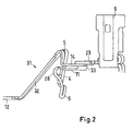
- FIG. 2 shows in an isolated detail view of the extension 31 and its connection to the access terminal 9. It recognizes the one-piece execution of arc guide rails 12, first leg 32 and retaining leg 4 as a stamped and bent part made of steel. At the upper bending point, which forms the bearing end 5, the steel strip is slotted. This results in two parallel partial strips. One of these partial strips is bent as a holding leg 4 down. The adjacent partial strip is again bent downwards after a short course, pointing horizontally in the direction of the access clamp 9. It thus forms the first conductor piece 14, which is at a contact point 33 with the busbar of the access terminal 9, the terminal rail 29, welded.
- a second conductor piece 11 is additionally attached. This is here a copper bar, which may be soldered to the pad 33, for example.
- the other end of the second conductor piece 11 is at the free end 6 of the Holding leg 4 attached, for example, also soldered. So that the mobility of the retaining leg 4 is not hindered, the second conductor piece 11 is made slightly longer than necessary, and carries in the central region a loop-shaped bulge 28.
- a first portion of the second conductor piece 11 thus extends from the contact point 33 from parallel to the first conductor piece 14, approximately up to the height of the retaining leg 4. Then the loop-like bulge 28 joins, at the end of which a straight section extends again approximately parallel to the retaining leg 4 towards the free end 6.
- the loop-like bulge ensures that the second conductor piece 11 is not a hindrance to pivoting of the retaining leg 4 in the course of adjustment in the way.
- the second portion is shown generally as a conductor piece guided around the adjustment screw 13.
- a movable strand could be provided. However, such would be more difficult to assemble with automatic assembly machines than a solid sheet. In a hand assembly, however, a strand would be an advantageous alternative.
- the second copper conductor piece 11 creates a bypass connection that provides a lower resistivity parallel conductor path. This is, as already explained above, advantageous in particular at high rated currents. Without the second conductor piece 11, the steel conductor pieces would strongly heat up at high rated currents because of the relatively high resistivity of steel. The heat would radiate to the bimetallic strip 2, as a result, this could already bend strongly at rated current and cause too early triggering, which should be avoided.
Landscapes
- Physics & Mathematics (AREA)
- Electromagnetism (AREA)
- Breakers (AREA)
- Thermally Actuated Switches (AREA)
Abstract
Description
- Die Erfindung betrifft ein elektrisches Schaltgerät, insbesondere einen Leitungsschutzschalter, mit einem zwischen einer ersten und einer zweiten Anschlussklemme verlaufenden Strompfad, mit einem thermischen Auslöser umfassend einen Streifen aus Thermobimetall oder aus einer Formgedächtnislegierung, wobei der Streifen mit seinem Befestigungsende an dem freien Ende eines an einem Lagerende beweglich gelagerten Halteschenkel befestigt ist und an seinem Betätigungsende in Wirkverbindung mit einem Schaltschloss steht, wobei der Strompfad von der ersten Klemme über ein erstes Leiterstück zu dem Lagerende und weiter über das freie Ende des Halteschenkels, sowie das Befestigungsende und das Betätigungsende des Streifens führt, gemäß dem Oberbegriff des Anspruches 1.
- Ein gattungsgemäßer Leitungsschutzschalter ist beispielsweise in der
DE 10 2008 006 863 A1 gezeigt. Er besitzt eine Zugangs- und eine Abgangsklemme mit einem dazwischen durch das Schaltgerät geführten Strompfad. Der Strompfad führt über eine Kontaktstelle, die zwischen einem auf einem beweglichen Kontakthebel gelagerten beweglichen und einem festen Kontaktstück gebildet ist, sowie mindestens über einen thermischen, oft zusätzlich noch über einen elektromagnetischen Auslöser, von denen der thermische Auslöser beim Auftreten eines Überstromes und der elektromagnetische Auslöser bei Auftreten eines Kurzschlussstromes zur Ausschaltung des Schaltgerätes beitragen. Dabei wirkt der thermische Auslöser bei einer Auslösung auf eine Verklinkungsstelle innerhalb eines Schaltschlosses, das mit dem beweglichen Kontakthebel gekoppelt ist, zu deren Entklinkung ein. Ist die Verklinkungsstelle entklinkt, wird der Kontakthebel verschwenkt, so dass das bewegliche und das freie Kontaktstück getrennt werden. Der elektromagnetische Auslöser öffnet bei Auftreten eines Kurzschlussstromes den Kontakthebel unmittelbar durch Aufschlagen; gleichzeitig betätigt der elektromagnetische Auslöser auch das Schaltschloss, damit das Schaltgerät bleibend geöffnet ist. - Zu Justierzwecken ist der Thermobimetallstreifen in gattungsgemäßen elektrischen Schaltgeräten am freien Ende eines beweglich gelagerten Halteschenkels befestigt. Aus Platz- und Montagegründen verläuft der Strompfad, von der Zugangsklemme kommend, zunächst über ein erstes Leiterstück zu dem Lagerende des Halteschenkels, dann durch den Halteschenkel und den Thermobimetallstreifen hindurch und schließlich weiter in das Geräteinnere. Der Thermobimetallstreifen ist dabei direkt vom Strom des Strompfades durchflossen, man spricht von einem direkt beheizten Thermobimetall. Bei hohen Nennströmen kann es wegen des Widerstandes des ersten Leiterstücks und des Halteschenkels dort zu einem unerwünscht hohen Spannungsabfall und einer unerwünschten Erwärmung kommen.
- Der vorliegenden Erfindung liegt im Lichte des Standes der Technik daher die Aufgabe zugrunde, ein gattungsgemäßes elektrisches Schaltgerät so weiterzuentwickeln, dass der elektrische Widerstand zwischen der Zugangsklemme und dem Bimetallstreifen verringert ist.
- Die der Erfindung zugrundeliegende Aufgabe wird erfindungsgemäß gelöst mit den kennzeichnenden Merkmalen des Anspruches 1.
- Erfindungsgemäß sind die ersten Klemmen und das Befestigungsende des Streifens zusätzlich über ein zweites Leiterstück verbunden, das eine höhere Leitfähigkeit hat als der Halteschenkel. Das zweite Leiterstück schafft gewissermaßen einen Bypass-Leiter mit geringem elektrischen Widerstand, der elektrisch parallel zu dem Halteschenkel geschaltet ist. Der resultierende Gesamtwiderstand zwischen der Klemme und der Befestigungsstelle des Thermobimetalls wird dadurch sehr klein, wegen der Parallelschaltung kleiner als der kleinste Einzelwiderstand. Auch bei hohen Nennströmen kann jetzt keine übergroße Erwärmung und kein großer Spannungsabfall mehr auftreten.
- Gemäß einer besonderes vorteilhaften Ausführungsform der Erfindung umfasst das Schaltgerät eine Lichtbogenleitschiene mit einem gehäusefest gelagerten Fortsatz, dessen freies Ende den Halteschenkel zur Befestigung des Streifens bildet und dazu U-förmig umgebogen und an der das Lagerende bildenden Biegestelle schwenkbeweglich gelagert ist. Vorteilhaft daran ist, dass das Lagerende für den Halteschenkel durch dessen Verbindung mit der gehäusefest gelagerten Lichtbogenleitschiene beziehungsweise dem gehäusefest gelagerten Fortsatz der Lichtbogenleitschiene ebenfalls gehäusefest gehalten ist, was günstig ist für die Reproduzierbarkeit der thermischen Justierung des thermischen Bimetallauslösers.
- Gemäß einer vorteilhaften Ausführungsform der Erfindung ist der Halteschenkel mit einem Justiermittel zur Justierung des thermischen Auslösers verschwenkbar. Das Justiermittel kann beispielsweise eine Einstellschraube sein.
- Gemäß einer besonders vorteilhaften Ausführungsform der Erfindung ist das zweite Leiterstück ein Leiterstreifen mit einer schleifenartigen Ausbauchung. Ein Leiterstreifen hat eine gewisse Steifigkeit und Festigkeit und eignet sich deshalb besonders gut für eine automatische Fertigung, bei der die einzelnen Teile durch Handhabungsautomaten sehr präzise zur Montage in das geöffnete Gehäuse zugeführt werden sollen. Die schleifenartige Ausbauchung sorgt dafür, dass das zweite Leiterstück dennoch etwas nachgeben kann, wenn das Befestigungsende des Thermobimetallstreifens beim Justieren etwas verschwenkt wird und sich dadurch dann sein Abstand von der Zugangsklemme ändert.
- Gemäß einer weiteren vorteilhaften Ausführungsform der Erfindung ist das zweite Leiterstück eine bewegliche Litze. Diese kann aufgrund ihrer Flexibilität sehr gut einer Verschwenkung des Befestigungsendes des Thermobimetallstreifens folgen.
- Gemäß einer besonders vorteilhaften Ausführungsform der Erfindung besteht der Halteschenkel aus Stahl und das zweite Leiterstück aus Kupfer besteht. Stahl ist preiswert und erfüllt die Anforderungen an Formbeständigkeit und Festigkeit, hat aber einen relativ hohen spezifischen Widerstand. Kupfer hat die erforderliche hohe elektrische Leitfähigkeit, bei allerdings verminderter mechanischer Festigkeit.
- Weiter vorteilhafte Ausgestaltungen und Verbesserungen der Erfindung und weitere Vorteile sind den Unteransprüchen zu entnehmen.
- Figuren und Beschreibung dienen dem besseren Verständnis des Gegenstands. Gegenstände oder Teile von Gegenständen, die im Wesentlichen gleich oder ähnlich sind, können mit denselben Bezugszeichen versehen sein. Die Figuren sind lediglich eine schematische Darstellung einer Ausführungsform der Erfindung.
- Dabei zeigt:
- Fig. 1
- eine Ansicht eines erfindungsgemäßen elektromagnetischen Auslösers, und
- Fig. 2
- eine schematische Ansicht eines Installationsschaltgerätes mit einem er- findungsgemäßen elektromagnetischen Auslöser.
- In den Figuren sind gleiche oder gleichwirkende Bauteile oder Elemente mit den gleichen Bezugsziffern versehen.
-
Figur 1 zeigt schematisch eine Einsicht in ein geöffnetes Gehäuse eines elektrischen Installationsgerätes 1, hier eines Leitungsschutzschalters. Zwischen einer Zugangsklemme 9 und einer Abgangsklemme 10 verläuft ein Strompfad zunächst über eine Klemmenschiene 29, ein daran angeschweißtes erstes Leiterstück 14, zu dem Lagerende 5 eines Halteschenkels 4. An dem freien Ende 6 des Halteschenkels 4 ist ein Streifen 2 aus Thermobimetall mit seinem Befestigungsende 3 angeschweißt. Das gegenüberliegende, freie Ende 7 des Thermobimetallstreifens 2 ist mit einer Litze 20 verbunden. Diese führt den Stromfluss an einen in einer Lagerstelle 21 verschwenkbar gelagerten Kontakthebel 17, der an seinem freien Ende ein bewegliches Kontaktstück 18 trägt. Dieses bildet zusammen mit einem festen Kontaktstück 19 eine Kontaktstelle. Von dem festen Kontaktstück 19 läuft der Strompfad weiter über einen magnetischen Auslöser 16 zu der Abgangsklemme 10. - Wenn der Strom im Hauptstrompfad längere Zeit über dem Nennstrom bleibt, man spricht dann von einem Überstrom, biegt sich der Thermobimetallstreifen 2 mit seinem freien, dem Befestigungsende gegenüberliegenden Ende aufgrund der in ihm durch den Überstrom hervorgerufenen Stromwärme so weit aus, dass er über eine Wirklinie 22 auf ein Schaltschloss 8 einwirkt und dort dafür sorgt, dass eine Verklinkungsstelle entklinkt wird. Die Realisierung der Wechselwirkung des Thermobimetallstreifens mit dem Schaltschloss 8 ist auf verschiedene Weisen realisierbar, eine Möglichkeit ist in der bereits erwähnten
DE 10 2008 006 863 A1 dargestellt. Nach dem Entklinken der Verklinkungsstelle wirkt das Schaltwerk über eine Wirklinie 24 auf den Kontakthebel 17 ein und verschwenkt diesen im Uhrzeigersinn, so dass das bewegliche Kontaktstück 18 von dem festen Kontaktstück 19 getrennt und die Kontaktstelle geöffnet und durch das Schaltschloss 8 offengehalten wird. Ein Wiedereinschalten kann über einen Schaltknauf 27 erfolgen, der über eine Wirklinie 26 mit dem Schaltschloss 8 zusammenwirkt und bei Betätigung ein Wiederverklinken der Verklinkungsstelle erlaubt, wenn das Thermobimetall 2 sich wieder in seine Ausgangsposition zurückgebogen hat, nachdem der Überstrom abgeklungen ist. Die Justierung des Thermobimetalls 2 erfolgt über eine Einstellschraube 13. Diese verschwenkt den Halteschenkel 4 um dessen Lagerende 5. Da der Thermobimetallstreifen 2 unten an dem Halteschenkel 4 angeschweißt ist, ist durch Verschwenken des Halteschenkels 4 der Abstand des freien Betätigungsendes 7 des Thermobimetallstreifens 2 von dem Schaltschloss 8 einstellbar. - Wenn ein Kurzschlussstrom durch den Strompfad fließt, also ein in sehr kurzer Zeit auf ein Mehrfaches des Nennstroms ansteigender Strom, so spricht der Magnetauslöser 16 an. Dieser schlägt dann über eine Wirklinie 25 direkt und schnell den Kontakthebel 17 auf, gleichzeitig wirkt er über eine Wirklinie 23 auch auf das Schaltschloss 8 zu dessen Entklinkung und zur dauerhaften Offenhaltung der Kontaktstelle ein.
- Bei einem schnellen Aufschlagen der Kontaktstelle entsteht zwischen den sich auseinander bewegenden Kontaktstücken ein Schaltlichtbogen. Dieser kommutiert nach kurzer Zeit auf eine Festkontaktleitschiene 30 und eine Lichtbogenleitschiene 12 und wird von beiden in eine Lichtbogenlöschkammer 15 zum Verlöschen geführt.
- Die Lichtbogenleitschiene 12 trägt an ihrer rechten, der Kontaktstelle zugewandten Seite, einen Fortsatz 31. Dieser hat ungefähr eine U-Form, mit einem ersten Schenkel 32, der direkt mit der Lichtbogenleitschiene 12 verbunden ist, und einem zweiten Schenkel, der den Halteschenkel 4 bildet. Der Halteschenkel 4 entsteht durch Umbiegen des Fortsatzes 31 an einer Biegestelle, die oben auch als Lagerende 5 für den Halteschenkel 4 bezeichnet wurde. Die Lichtbogenleitschiene 12 mit dem Fortsatz 31 kann aus einem Teil gefertigt sein. Vorteilhafterweise ist dieses ein Stanzbiegeteil aus Stahl. Stahl wird wegen seiner magnetischen Eigenschaft, seiner Festigkeit und seiner geringen Kosten wegen bevorzugt verwendet. Die Leitschiene 12 und der erste Schenkel 32 sind gehäusefest gelagert und gehalten, was auf verschiedene Arten ermöglicht werden kann, beispielsweise durch Festklemmen zwischen Stegen auf der Gehäuseinnenseite. Der Halteschenkel 4 muss beweglich bleiben, wie oben im Zusammenhang mit der Justierung des Thermobimetalls erläutert worden war. Der feste Sitz des ersten Schenkels 32 ist wichtig im Hinblick auf die Konstanz der thermischen Auslöseeigenschaften, da dadurch die Lage des Thermobimetalls 2 relativ zu dem Schaltschloss 8 auch festgelegt bleibt, nachdem einmal justiert wurde.
-
Figur 2 zeigt in einer herausgelösten Detailansicht den Fortsatz 31 und seine Anbindung an die Zugangsklemme 9. Man erkennt die einstückige Ausfühung von Lichtbogenleitschienen 12, erstem Schenkel 32 und Halteschenkel 4 als Stanzbiegeteil aus Stahl. An der oberen Biegestelle, die das Lagerende 5 bildet, ist der Stahlstreifen geschlitzt. Es entstehen dadurch zwei parallel verlaufende Teilstreifen. Einer dieser Teilstreifen ist als Halteschenkel 4 nach unten gebogen. Der daneben liegende Teilstreifen ist nach einem kurzen Verlauf senkrecht nach unten erneut umgebogen, waagerecht in Richtung auf die Zugangsklemme 9 hin weisend. Er bildet somit das erste Leiterstück 14, das an einer Kontaktstelle 33 mit der Stromschiene der Zugangsklemme 9, der Klemmenschiene 29, verschweißt ist. - An der Kontaktstelle 33 ist zusätzlich ein zweites Leiterstück 11 befestigt. Dieses ist hier eine Kupferschiene, die an der Kontaktstelle 33 beispielsweise angelötet sein kann. Das andere Ende des zweiten Leiterstücks 11 ist an dem freien Ende 6 des Halteschenkels 4 befestigt, beispielsweise ebenfalls verlötet. Damit die Beweglichkeit des Halteschenkels 4 nicht behindert wird, ist das zweite Leiterstück 11 etwas länger ausgeführt als nötig, und trägt im mittleren Bereich eine schleifenförmige Ausbauchung 28. Ein erstes Teilstück des zweiten Leiterstücks 11 verläuft also von der Kontaktstelle 33 aus parallel zu dem ersten Leiterstück 14, etwa bis auf Höhe des Halteschenkels 4. Dann schließt sich die schleifenartige Ausbauchung 28 an, an deren Ende sich wieder ein gerades Teilstück in etwa parallel zu dem Halteschenkel 4 hin zu dem freien Ende 6 erstreckt. Die schleifenartige Ausbauchung gewährleistet, dass das zweite Leiterstück 11 einer Verschwenkung des Halteschenkels 4 im Zuge der Justierung nicht hindernd im Wege steht. In der schematischen Darstellung der
Fig. 1 ist das zweite Teilstück allgemein als ein um die Justierschraube 13 herumgeführtes Leiterstück dargestellt. - Es sind selbstverständlich auch noch andere Realisierungsmöglichkeiten als die in der
Fig. 2 dargestellte denkbar. Beispielsweise könnte eine bewegliche Litze vorgesehen werden. Eine solche wäre allerdings mit Montageautomaten schwieriger zu montieren als ein festes Blech. Bei einer Handmontage wäre allerdings eine Litze eine vorteilhafte Alternative. - Ohne das zweite Leiterstück würde der Strompfad von der Zugangsklemme 9 kommend über die Kontaktstelle 33 und das erste Leiterstück 14 zu dem Lagerende 5 und von dort über den Halteschenkel 4 zu dem freien Ende 6 verlaufen, wo das Thermobimetall 2 angeschweißt ist und der Strompfad in das Thermobimetall übertritt. Das zweite Leiterstück 11 aus Kupfer schafft eine Bypass-Verbindung, die einen parallelen Leiterpfad mit geringerem Widerstand schafft. Das ist, wie oben bereits erläutert, vorteilhaft insbesondere bei hohen Nennströmen. Ohne das zweite Leiterstück 11 würden sich die Leiterstücke aus Stahl bei hohen Nennströmen wegen des relativ hohen spezifischen Widerstandes von Stahl stark erwärmen. Die Wärme würde auf das Thermobimetall 2 abgestrahlt, in der Folge könnte sich dieses bereits bei Nennstrom stark verbiegen und ein zu frühes Auslösen bewirken, was vermieden werden soll.
Bezugszeichenliste 1 Elektrisches Schaltgerät 30 Festkontaktleitschiene 2 Streifen aus Thermobimetall 31 Fortsatz 3 Befestigungsende 32 erster Schenkel 4 Halteschenkel 33 Kontaktstelle 5 Lagerende 6 freies Ende 7 Betätigungsende 8 Schaltschloss 9 erste Anschlussklemme 10 zweite Anschlussklemme 11 zweites Leiterstück 12 Lichtbogenleitschiene 13 Justiermittel 14 erstes Leiterstück 15 Lichtbogenlöschkammer 16 magnetischer Auslöser 17 Kontakthebel 18 bewegliches Kontaktstück 19 festes Kontaktstück 20 Litze 21 Lagerstelle 22 Wirklinie 23 Wirklinie 24 Wirklinie 25 Wirklinie 26 Wirklinie 27 Schaltknauf 28 Bauch 29 Klemmenschiene
Claims (6)
- Elektrisches Schaltgerät (1), insbesondere Leitungsschutzschalter, mit einem zwischen einer ersten und einer zweiten Anschlussklemme (9, 10) verlaufenden Strompfad, mit einem thermischen Auslöser umfassend einen Streifen (2) aus Thermobimetall oder aus einer Formgedächtnislegierung, wobei der Streifen (2) mit seinem Befestigungsende (3) an dem freien Ende (6) eines an einem Lagerende (5) beweglich gelagerten Halteschenkels (4) befestigt ist und an seinem Betätigungsende (7) in Wirkverbindung mit einem Schaltschloss (8) steht, wobei der Strompfad von der ersten Klemme (9) über ein erstes Leiterstück (14) zu dem Lagerende (5) und weiter über das freie Ende (6) des Halteschenkels (4), sowie das Befestigungsende (3) und das Betätigungsende (7) des Streifens (2) führt,
dadurch gekennzeichnet, dass die erste Klemme (9) und das Befestigungsende (3) des Streifens (2) zusätzlich über ein zweites Leiterstück (11) verbunden sind, das eine höhere Leitfähigkeit hat als der Halteschenkel (4). - Elektrisches Schaltgerät (1) nach Anspruch 1, dadurch gekennzeichnet, dass das Schaltgerät (1) eine Lichtbogenleitschiene (12) umfasst, mit einem gehäusefest gelagerten Fortsatz (13), dessen freies Ende den Halteschenkel (4) zur Befestigung des Streifens (2) bildet und dazu U-förmig umgebogen und an der das Lagerende (5) bildenden Biegestelle schwenkbeweglich gelagert ist.
- Elektrisches Schaltgerät (1) nach Anspruch 1, dadurch gekennzeichnet, dass der Halteschenkel (4) mit einem Justiermittel (13) zur Justierung des thermischen Auslösers verschwenkbar ist.
- Elektrisches Schaltgerät (1) nach Anspruch 1, dadurch gekennzeichnet, dass das zweite Leiterstück (11) ein Leiterstreifen mit einer schleifenartigen Ausbauchung ist.
- Elektrisches Schaltgerät (1) nach Anspruch 1, dadurch gekennzeichnet, dass das zweite Leiterstück (11) eine bewegliche Litze ist.
- Elektrisches Schaltgerät nach Anspruch 1, dadurch gekennzeichnet, dass der Halteschenkel aus Stahl und das zweite Leiterstück (11) aus Kupfer besteht.
Applications Claiming Priority (1)
| Application Number | Priority Date | Filing Date | Title |
|---|---|---|---|
| DE102009023557A DE102009023557B3 (de) | 2009-05-30 | 2009-05-30 | Elektrisches Schaltgerät mit einem thermischen Auslöser |
Publications (3)
| Publication Number | Publication Date |
|---|---|
| EP2256778A2 true EP2256778A2 (de) | 2010-12-01 |
| EP2256778A3 EP2256778A3 (de) | 2011-03-23 |
| EP2256778B1 EP2256778B1 (de) | 2011-11-23 |
Family
ID=42309157
Family Applications (1)
| Application Number | Title | Priority Date | Filing Date |
|---|---|---|---|
| EP10004302A Active EP2256778B1 (de) | 2009-05-30 | 2010-04-22 | Elektrisches Schaltgerät mit einem thermischen Auslöser |
Country Status (5)
| Country | Link |
|---|---|
| EP (1) | EP2256778B1 (de) |
| CN (1) | CN201629238U (de) |
| AT (1) | ATE535005T1 (de) |
| DE (1) | DE102009023557B3 (de) |
| ES (1) | ES2377549T3 (de) |
Cited By (1)
| Publication number | Priority date | Publication date | Assignee | Title |
|---|---|---|---|---|
| EP2254138A3 (de) * | 2009-05-18 | 2013-03-06 | Abb Ag | Thermischer Auslöser und elektrisches Schaltgerät mit einem thermischen Auslöser |
Families Citing this family (1)
| Publication number | Priority date | Publication date | Assignee | Title |
|---|---|---|---|---|
| EP2608233A1 (de) * | 2011-12-23 | 2013-06-26 | Abb Ag | Elektrischer Lasttrennschalter für Niederspannung |
Citations (1)
| Publication number | Priority date | Publication date | Assignee | Title |
|---|---|---|---|---|
| DE102008006863A1 (de) | 2007-05-23 | 2009-01-22 | Abb Ag | Elektrisches Installationsschaltgerät |
Family Cites Families (3)
| Publication number | Priority date | Publication date | Assignee | Title |
|---|---|---|---|---|
| DE4202122C2 (de) * | 1992-01-27 | 1994-08-25 | Kloeckner Moeller Gmbh | Auslöseeinrichtung für Schaltgeräte |
| CH685524A5 (de) * | 1993-03-19 | 1995-07-31 | Maier & Cie C | Leitungsschutzschalter. |
| US5872495A (en) * | 1997-12-10 | 1999-02-16 | Siemens Energy & Automation, Inc. | Variable thermal and magnetic structure for a circuitbreaker trip unit |
-
2009
- 2009-05-30 DE DE102009023557A patent/DE102009023557B3/de not_active Expired - Fee Related
- 2009-07-24 CN CN2009201627359U patent/CN201629238U/zh not_active Expired - Lifetime
-
2010
- 2010-04-22 EP EP10004302A patent/EP2256778B1/de active Active
- 2010-04-22 ES ES10004302T patent/ES2377549T3/es active Active
- 2010-04-22 AT AT10004302T patent/ATE535005T1/de active
Patent Citations (1)
| Publication number | Priority date | Publication date | Assignee | Title |
|---|---|---|---|---|
| DE102008006863A1 (de) | 2007-05-23 | 2009-01-22 | Abb Ag | Elektrisches Installationsschaltgerät |
Cited By (1)
| Publication number | Priority date | Publication date | Assignee | Title |
|---|---|---|---|---|
| EP2254138A3 (de) * | 2009-05-18 | 2013-03-06 | Abb Ag | Thermischer Auslöser und elektrisches Schaltgerät mit einem thermischen Auslöser |
Also Published As
| Publication number | Publication date |
|---|---|
| DE102009023557B3 (de) | 2010-08-05 |
| EP2256778B1 (de) | 2011-11-23 |
| ES2377549T3 (es) | 2012-03-28 |
| EP2256778A3 (de) | 2011-03-23 |
| ATE535005T1 (de) | 2011-12-15 |
| CN201629238U (zh) | 2010-11-10 |
Similar Documents
| Publication | Publication Date | Title |
|---|---|---|
| EP2143122B1 (de) | Installationsschaltgerät | |
| DE102009021773B4 (de) | Thermischer Auslöser und elektrisches Schaltgerät mit einem thermischen Auslöser | |
| DE7714923U1 (de) | Überstromschutzschalter mit Ein- und Ausschaltwippe | |
| EP0563775B1 (de) | Bimetallgesteuerter Schutzschalter | |
| EP0849761B1 (de) | Überstrom- und Kurzschlussauslöser für einen elektrischen Installationsschalter | |
| EP2256778B1 (de) | Elektrisches Schaltgerät mit einem thermischen Auslöser | |
| DE102012111618A1 (de) | Leitungsschutzschalter mit passiv beheiztem Bimetall-Element | |
| DE7314251U (de) | Kontaktklemme | |
| DE102010050870B4 (de) | Niederspannungsschaltgerät mit einer Steckklemmvorrichtung | |
| EP3970177B1 (de) | Schutzschalter | |
| DE102012013433B4 (de) | Installationsschaltgerät mit einem thermomechanischen Wandler | |
| EP1735803B1 (de) | Schaltvorrichtung | |
| EP2824689B1 (de) | Dynamischer Auslöser und elektrisches Installationsschaltgerät mit einem dynamischen Auslöser | |
| DE102013019337A1 (de) | Auslöserbaugruppe | |
| EP2387060B1 (de) | Thermischer Auslöser | |
| DE102010005345B4 (de) | Elektrisches Schaltgerät in modularer Bauweise | |
| DE102019117804B4 (de) | Schalteinrichtung mit einem elektrischen Kontaktsystem | |
| DE102008020453A1 (de) | Installationsschaltgerät mit einem thermischen Auslöser | |
| DE102013002470B4 (de) | Thermischer Auslöser und lnstallationsschaltgerät mit einem thermischen Auslöser | |
| EP2437353A1 (de) | Installationsschaltgerät mit einer Steckklemmvorrichtung | |
| DE202018104529U1 (de) | Trennschalter | |
| DE102017202790B4 (de) | Elektromechanisches Schutzschaltgerät | |
| DE10102436B4 (de) | Thermische Auslösevorrichtung für ein Schaltgerät | |
| DE102014002161A1 (de) | Festkontaktträger, Auslöserbaugruppe mit Festkontaktträger und Installationsschaltgerät mit Festkontaktträger | |
| DE102007010946B4 (de) | Überlastauslöser für ein mehrpoliges elektrisches Schaltgerät |
Legal Events
| Date | Code | Title | Description |
|---|---|---|---|
| PUAI | Public reference made under article 153(3) epc to a published international application that has entered the european phase |
Free format text: ORIGINAL CODE: 0009012 |
|
| AK | Designated contracting states |
Kind code of ref document: A2 Designated state(s): AT BE BG CH CY CZ DE DK EE ES FI FR GB GR HR HU IE IS IT LI LT LU LV MC MK MT NL NO PL PT RO SE SI SK SM TR |
|
| AX | Request for extension of the european patent |
Extension state: AL BA ME RS |
|
| PUAL | Search report despatched |
Free format text: ORIGINAL CODE: 0009013 |
|
| AK | Designated contracting states |
Kind code of ref document: A3 Designated state(s): AT BE BG CH CY CZ DE DK EE ES FI FR GB GR HR HU IE IS IT LI LT LU LV MC MK MT NL NO PL PT RO SE SI SK SM TR |
|
| AX | Request for extension of the european patent |
Extension state: AL BA ME RS |
|
| RIC1 | Information provided on ipc code assigned before grant |
Ipc: H01H 71/40 20060101ALI20110217BHEP Ipc: H01H 71/16 20060101AFI20100907BHEP Ipc: H01H 71/08 20060101ALI20110217BHEP |
|
| 17P | Request for examination filed |
Effective date: 20110421 |
|
| GRAP | Despatch of communication of intention to grant a patent |
Free format text: ORIGINAL CODE: EPIDOSNIGR1 |
|
| RIC1 | Information provided on ipc code assigned before grant |
Ipc: H01H 71/08 20060101ALI20110712BHEP Ipc: H01H 71/16 20060101AFI20110712BHEP Ipc: H01H 71/40 20060101ALI20110712BHEP |
|
| GRAS | Grant fee paid |
Free format text: ORIGINAL CODE: EPIDOSNIGR3 |
|
| GRAA | (expected) grant |
Free format text: ORIGINAL CODE: 0009210 |
|
| AK | Designated contracting states |
Kind code of ref document: B1 Designated state(s): AT BE BG CH CY CZ DE DK EE ES FI FR GB GR HR HU IE IS IT LI LT LU LV MC MK MT NL NO PL PT RO SE SI SK SM TR |
|
| REG | Reference to a national code |
Ref country code: GB Ref legal event code: FG4D Free format text: NOT ENGLISH |
|
| REG | Reference to a national code |
Ref country code: CH Ref legal event code: EP |
|
| REG | Reference to a national code |
Ref country code: IE Ref legal event code: FG4D Free format text: LANGUAGE OF EP DOCUMENT: GERMAN |
|
| REG | Reference to a national code |
Ref country code: DE Ref legal event code: R096 Ref document number: 502010000228 Country of ref document: DE Effective date: 20120202 |
|
| REG | Reference to a national code |
Ref country code: NL Ref legal event code: VDEP Effective date: 20111123 |
|
| REG | Reference to a national code |
Ref country code: ES Ref legal event code: FG2A Ref document number: 2377549 Country of ref document: ES Kind code of ref document: T3 Effective date: 20120328 |
|
| LTIE | Lt: invalidation of european patent or patent extension |
Effective date: 20111123 |
|
| PG25 | Lapsed in a contracting state [announced via postgrant information from national office to epo] |
Ref country code: LT Free format text: LAPSE BECAUSE OF FAILURE TO SUBMIT A TRANSLATION OF THE DESCRIPTION OR TO PAY THE FEE WITHIN THE PRESCRIBED TIME-LIMIT Effective date: 20111123 Ref country code: NO Free format text: LAPSE BECAUSE OF FAILURE TO SUBMIT A TRANSLATION OF THE DESCRIPTION OR TO PAY THE FEE WITHIN THE PRESCRIBED TIME-LIMIT Effective date: 20120223 Ref country code: IS Free format text: LAPSE BECAUSE OF FAILURE TO SUBMIT A TRANSLATION OF THE DESCRIPTION OR TO PAY THE FEE WITHIN THE PRESCRIBED TIME-LIMIT Effective date: 20120323 |
|
| PG25 | Lapsed in a contracting state [announced via postgrant information from national office to epo] |
Ref country code: HR Free format text: LAPSE BECAUSE OF FAILURE TO SUBMIT A TRANSLATION OF THE DESCRIPTION OR TO PAY THE FEE WITHIN THE PRESCRIBED TIME-LIMIT Effective date: 20111123 Ref country code: GR Free format text: LAPSE BECAUSE OF FAILURE TO SUBMIT A TRANSLATION OF THE DESCRIPTION OR TO PAY THE FEE WITHIN THE PRESCRIBED TIME-LIMIT Effective date: 20120224 Ref country code: PT Free format text: LAPSE BECAUSE OF FAILURE TO SUBMIT A TRANSLATION OF THE DESCRIPTION OR TO PAY THE FEE WITHIN THE PRESCRIBED TIME-LIMIT Effective date: 20120323 Ref country code: LV Free format text: LAPSE BECAUSE OF FAILURE TO SUBMIT A TRANSLATION OF THE DESCRIPTION OR TO PAY THE FEE WITHIN THE PRESCRIBED TIME-LIMIT Effective date: 20111123 Ref country code: SE Free format text: LAPSE BECAUSE OF FAILURE TO SUBMIT A TRANSLATION OF THE DESCRIPTION OR TO PAY THE FEE WITHIN THE PRESCRIBED TIME-LIMIT Effective date: 20111123 Ref country code: SI Free format text: LAPSE BECAUSE OF FAILURE TO SUBMIT A TRANSLATION OF THE DESCRIPTION OR TO PAY THE FEE WITHIN THE PRESCRIBED TIME-LIMIT Effective date: 20111123 Ref country code: NL Free format text: LAPSE BECAUSE OF FAILURE TO SUBMIT A TRANSLATION OF THE DESCRIPTION OR TO PAY THE FEE WITHIN THE PRESCRIBED TIME-LIMIT Effective date: 20111123 |
|
| REG | Reference to a national code |
Ref country code: IE Ref legal event code: FD4D |
|
| PG25 | Lapsed in a contracting state [announced via postgrant information from national office to epo] |
Ref country code: CY Free format text: LAPSE BECAUSE OF FAILURE TO SUBMIT A TRANSLATION OF THE DESCRIPTION OR TO PAY THE FEE WITHIN THE PRESCRIBED TIME-LIMIT Effective date: 20111123 |
|
| PG25 | Lapsed in a contracting state [announced via postgrant information from national office to epo] |
Ref country code: IE Free format text: LAPSE BECAUSE OF FAILURE TO SUBMIT A TRANSLATION OF THE DESCRIPTION OR TO PAY THE FEE WITHIN THE PRESCRIBED TIME-LIMIT Effective date: 20111123 Ref country code: CZ Free format text: LAPSE BECAUSE OF FAILURE TO SUBMIT A TRANSLATION OF THE DESCRIPTION OR TO PAY THE FEE WITHIN THE PRESCRIBED TIME-LIMIT Effective date: 20111123 Ref country code: DK Free format text: LAPSE BECAUSE OF FAILURE TO SUBMIT A TRANSLATION OF THE DESCRIPTION OR TO PAY THE FEE WITHIN THE PRESCRIBED TIME-LIMIT Effective date: 20111123 Ref country code: BG Free format text: LAPSE BECAUSE OF FAILURE TO SUBMIT A TRANSLATION OF THE DESCRIPTION OR TO PAY THE FEE WITHIN THE PRESCRIBED TIME-LIMIT Effective date: 20120223 Ref country code: SK Free format text: LAPSE BECAUSE OF FAILURE TO SUBMIT A TRANSLATION OF THE DESCRIPTION OR TO PAY THE FEE WITHIN THE PRESCRIBED TIME-LIMIT Effective date: 20111123 Ref country code: EE Free format text: LAPSE BECAUSE OF FAILURE TO SUBMIT A TRANSLATION OF THE DESCRIPTION OR TO PAY THE FEE WITHIN THE PRESCRIBED TIME-LIMIT Effective date: 20111123 |
|
| PG25 | Lapsed in a contracting state [announced via postgrant information from national office to epo] |
Ref country code: RO Free format text: LAPSE BECAUSE OF FAILURE TO SUBMIT A TRANSLATION OF THE DESCRIPTION OR TO PAY THE FEE WITHIN THE PRESCRIBED TIME-LIMIT Effective date: 20111123 Ref country code: PL Free format text: LAPSE BECAUSE OF FAILURE TO SUBMIT A TRANSLATION OF THE DESCRIPTION OR TO PAY THE FEE WITHIN THE PRESCRIBED TIME-LIMIT Effective date: 20111123 |
|
| PLBE | No opposition filed within time limit |
Free format text: ORIGINAL CODE: 0009261 |
|
| STAA | Information on the status of an ep patent application or granted ep patent |
Free format text: STATUS: NO OPPOSITION FILED WITHIN TIME LIMIT |
|
| 26N | No opposition filed |
Effective date: 20120824 |
|
| BERE | Be: lapsed |
Owner name: ABB A.G. Effective date: 20120430 |
|
| PG25 | Lapsed in a contracting state [announced via postgrant information from national office to epo] |
Ref country code: MC Free format text: LAPSE BECAUSE OF NON-PAYMENT OF DUE FEES Effective date: 20120430 |
|
| REG | Reference to a national code |
Ref country code: DE Ref legal event code: R097 Ref document number: 502010000228 Country of ref document: DE Effective date: 20120824 |
|
| PG25 | Lapsed in a contracting state [announced via postgrant information from national office to epo] |
Ref country code: BE Free format text: LAPSE BECAUSE OF NON-PAYMENT OF DUE FEES Effective date: 20120430 |
|
| PG25 | Lapsed in a contracting state [announced via postgrant information from national office to epo] |
Ref country code: MK Free format text: LAPSE BECAUSE OF FAILURE TO SUBMIT A TRANSLATION OF THE DESCRIPTION OR TO PAY THE FEE WITHIN THE PRESCRIBED TIME-LIMIT Effective date: 20111123 |
|
| PG25 | Lapsed in a contracting state [announced via postgrant information from national office to epo] |
Ref country code: FI Free format text: LAPSE BECAUSE OF FAILURE TO SUBMIT A TRANSLATION OF THE DESCRIPTION OR TO PAY THE FEE WITHIN THE PRESCRIBED TIME-LIMIT Effective date: 20111123 |
|
| PG25 | Lapsed in a contracting state [announced via postgrant information from national office to epo] |
Ref country code: MT Free format text: LAPSE BECAUSE OF FAILURE TO SUBMIT A TRANSLATION OF THE DESCRIPTION OR TO PAY THE FEE WITHIN THE PRESCRIBED TIME-LIMIT Effective date: 20111123 |
|
| PG25 | Lapsed in a contracting state [announced via postgrant information from national office to epo] |
Ref country code: TR Free format text: LAPSE BECAUSE OF FAILURE TO SUBMIT A TRANSLATION OF THE DESCRIPTION OR TO PAY THE FEE WITHIN THE PRESCRIBED TIME-LIMIT Effective date: 20111123 |
|
| PG25 | Lapsed in a contracting state [announced via postgrant information from national office to epo] |
Ref country code: SM Free format text: LAPSE BECAUSE OF FAILURE TO SUBMIT A TRANSLATION OF THE DESCRIPTION OR TO PAY THE FEE WITHIN THE PRESCRIBED TIME-LIMIT Effective date: 20111123 Ref country code: LU Free format text: LAPSE BECAUSE OF NON-PAYMENT OF DUE FEES Effective date: 20120422 |
|
| PG25 | Lapsed in a contracting state [announced via postgrant information from national office to epo] |
Ref country code: HU Free format text: LAPSE BECAUSE OF FAILURE TO SUBMIT A TRANSLATION OF THE DESCRIPTION OR TO PAY THE FEE WITHIN THE PRESCRIBED TIME-LIMIT Effective date: 20100422 |
|
| PGFP | Annual fee paid to national office [announced via postgrant information from national office to epo] |
Ref country code: ES Payment date: 20140428 Year of fee payment: 5 |
|
| REG | Reference to a national code |
Ref country code: CH Ref legal event code: PL |
|
| GBPC | Gb: european patent ceased through non-payment of renewal fee |
Effective date: 20140422 |
|
| PG25 | Lapsed in a contracting state [announced via postgrant information from national office to epo] |
Ref country code: LI Free format text: LAPSE BECAUSE OF NON-PAYMENT OF DUE FEES Effective date: 20140430 Ref country code: CH Free format text: LAPSE BECAUSE OF NON-PAYMENT OF DUE FEES Effective date: 20140430 Ref country code: GB Free format text: LAPSE BECAUSE OF NON-PAYMENT OF DUE FEES Effective date: 20140422 |
|
| REG | Reference to a national code |
Ref country code: FR Ref legal event code: PLFP Year of fee payment: 6 |
|
| PGFP | Annual fee paid to national office [announced via postgrant information from national office to epo] |
Ref country code: FR Payment date: 20150421 Year of fee payment: 6 Ref country code: IT Payment date: 20150422 Year of fee payment: 6 |
|
| REG | Reference to a national code |
Ref country code: ES Ref legal event code: FD2A Effective date: 20160526 |
|
| REG | Reference to a national code |
Ref country code: AT Ref legal event code: MM01 Ref document number: 535005 Country of ref document: AT Kind code of ref document: T Effective date: 20150422 |
|
| PG25 | Lapsed in a contracting state [announced via postgrant information from national office to epo] |
Ref country code: ES Free format text: LAPSE BECAUSE OF NON-PAYMENT OF DUE FEES Effective date: 20150423 |
|
| PG25 | Lapsed in a contracting state [announced via postgrant information from national office to epo] |
Ref country code: AT Free format text: LAPSE BECAUSE OF NON-PAYMENT OF DUE FEES Effective date: 20150422 |
|
| REG | Reference to a national code |
Ref country code: FR Ref legal event code: ST Effective date: 20161230 |
|
| PG25 | Lapsed in a contracting state [announced via postgrant information from national office to epo] |
Ref country code: FR Free format text: LAPSE BECAUSE OF NON-PAYMENT OF DUE FEES Effective date: 20160502 |
|
| PG25 | Lapsed in a contracting state [announced via postgrant information from national office to epo] |
Ref country code: IT Free format text: LAPSE BECAUSE OF NON-PAYMENT OF DUE FEES Effective date: 20160422 |
|
| PGFP | Annual fee paid to national office [announced via postgrant information from national office to epo] |
Ref country code: DE Payment date: 20250422 Year of fee payment: 16 |