EP2256767B1 - Heatpipe for terminal of circuit breaker - Google Patents
Heatpipe for terminal of circuit breaker Download PDFInfo
- Publication number
- EP2256767B1 EP2256767B1 EP10160990.7A EP10160990A EP2256767B1 EP 2256767 B1 EP2256767 B1 EP 2256767B1 EP 10160990 A EP10160990 A EP 10160990A EP 2256767 B1 EP2256767 B1 EP 2256767B1
- Authority
- EP
- European Patent Office
- Prior art keywords
- conducting body
- circuit breaker
- electric line
- electrical
- connection
- Prior art date
- Legal status (The legal status is an assumption and is not a legal conclusion. Google has not performed a legal analysis and makes no representation as to the accuracy of the status listed.)
- Active
Links
Images


Classifications
-
- H—ELECTRICITY
- H01—ELECTRIC ELEMENTS
- H01H—ELECTRIC SWITCHES; RELAYS; SELECTORS; EMERGENCY PROTECTIVE DEVICES
- H01H9/00—Details of switching devices, not covered by groups H01H1/00 - H01H7/00
- H01H9/52—Cooling of switch parts
-
- H—ELECTRICITY
- H01—ELECTRIC ELEMENTS
- H01H—ELECTRIC SWITCHES; RELAYS; SELECTORS; EMERGENCY PROTECTIVE DEVICES
- H01H1/00—Contacts
- H01H1/58—Electric connections to or between contacts; Terminals
-
- H—ELECTRICITY
- H02—GENERATION; CONVERSION OR DISTRIBUTION OF ELECTRIC POWER
- H02B—BOARDS, SUBSTATIONS OR SWITCHING ARRANGEMENTS FOR THE SUPPLY OR DISTRIBUTION OF ELECTRIC POWER
- H02B1/00—Frameworks, boards, panels, desks, casings; Details of substations or switching arrangements
- H02B1/56—Cooling; Ventilation
-
- H—ELECTRICITY
- H02—GENERATION; CONVERSION OR DISTRIBUTION OF ELECTRIC POWER
- H02B—BOARDS, SUBSTATIONS OR SWITCHING ARRANGEMENTS FOR THE SUPPLY OR DISTRIBUTION OF ELECTRIC POWER
- H02B11/00—Switchgear having carriage withdrawable for isolation
- H02B11/02—Details
- H02B11/04—Isolating-contacts, e.g. mountings or shieldings
-
- H—ELECTRICITY
- H01—ELECTRIC ELEMENTS
- H01H—ELECTRIC SWITCHES; RELAYS; SELECTORS; EMERGENCY PROTECTIVE DEVICES
- H01H9/00—Details of switching devices, not covered by groups H01H1/00 - H01H7/00
- H01H9/52—Cooling of switch parts
- H01H2009/523—Cooling of switch parts by using heat pipes
Definitions
- the present invention relates to a device for connecting an electric line to a connection terminal with a circuit breaker, and in particular to a connection device that in addition to enabling the electrical connection of the circuit breaker to an electric line, makes it possible to extract heat from the circuit breaker and transfer it to the electric line itself.
- low voltage breaking devices that is for applications with nominal voltages up to 1000V AC / 1500V DC
- switching devices are devices designed for allowing correct operation of specific parts of electrical systems and installed loads.
- Distribution switchboards normally comprise suitable cells or cubicles arranged for connecting the devices to the electrical power distribution lines.
- Distribution lines are normally constituted by systems of conductors, such as bus bars and/or cables.
- the use of appropriate distribution switchboards in addition to improving practicality, ergonomics of use, and the aesthetic appearance of the systems, contributes to maintain over time adequate safety conditions and correct functionality of all installed parts.
- a first installation method for circuit breakers is the so-called "fixed" execution wherein the electrical terminals of the circuit breaker are directly and stably connected to the conductors of the distribution lines. Such connection is normally done by using clamps or screws.
- a second installation method for circuit breakers is the so-called plug-in execution wherein special adapter devices are used which are mechanically connected to the switchboard, and connected stably to the conductors of the distribution lines by means of their own electrical terminals; each circuit breaker is mechanically coupled to a corresponding adapter device and by means of appropriate plug-in electrical terminals, it realizes the electrical connection to the distribution line; plug-in coupling normally includes plug-socket type mechanisms.
- a third installation method for the circuit breakers is the so-called withdrawable execution; it is substantially an evolution of the preceding removable method, wherein accessory elements are added such as guide and/or support and/or movement means for facilitating plugging and withdrawal operations of the circuit breaker.
- the first one is the simplest and cheapest, but it is only suitable to definitive solutions and in any case non-flexible; on the other hand, the removable and withdrawable-type methods offer a greater flexibility. These in fact allow - once the adapter is secured in the switchboard - very quick and totally safe installation or removal of the circuit breaker and, above all, without having to intervene directly on the distribution line.
- the undesired heat is generated both in the various conducting sections (for example made of copper) and, above all, at each of the present electrical couplings.
- the heat that is generated due to these dispersions contributes to increase the temperature of the system consisting of circuit breaker, cubicle and switchboard.
- the temperature of the circuit breaker and the temperature of the switchboard should be maintained within predefined operating limits, any undesired increase of electrical resistance in the conducting branches of the system consisting of the circuit breaker and its related adapter compels limiting the power that can be drawn by an apparatus.
- the temperature can negatively influence the operation of the circuit breakers. It is likewise known that the temperature of the circuit breaker tends to increase more rapidly if the characteristics of the used adapter, of the cubicle, and of the switchboard favor the accumulation of heat.
- patent US 3,662,137 discloses a switchgear having heat pipes incorporated in the disconnecting structures and power conductors, according to the preamble of claim 1.
- the main object of this invention is to face these problems and to provide a solution that makes it possible to improve the cooling of the circuit breaker, as well as the electrical switchboard overall inside which the circuit breaker is inserted.
- a device for connecting an electric line to a connection terminal for connection with a circuit breaker comprising:
- connection device for connecting an electric line to one or more terminals of a circuit breaker, without intending in any way to limit its scope of application to other electrical switching or breaking devices;
- circuit breaker it is to be understood any electrical breaking or switching device that is capable of passing from an open state to a closed state (and vice versa) and of breaking/restoring the current flow in an electrical circuit associated with it;
- such device can be constituted, for example, but not limited to, by a disconnector, or contactor, or an automatic switch (circuit breaker), namely a switching device designed ad hoc to intervene in the presence of significant electrical failure, etc.
- connection device comprises at least one first body 2, which is made of an electrically conducting material, for example, copper or aluminium, and has at least one first end portion 3 and a second end portion 4.
- the first portion 3 is intended in the installation phase to be connected to a circuit breaker 20, particularly to one of the terminals 21 the circuit breaker 20 is equipped with for input and output electrical connection with an associated electric line.
- the second end portion 4 is intended to be connected to a conductor element of the electric line, such as one or more bus bars 50, as illustrated for example in figure 13 .
- the end portion 4 comprises a clip 22 for the connection towards the electric line, for example, with corresponding conductors, indicated in figure 4 by reference number 23; obviously, this portion 4 can be configured in an entirely different manner according to the specific application (for example fixed, withdrawable, or removable).
- end portion 3 can be connected directly to a terminal 21 of a circuit breaker, as illustrated in figure 4 , or by means of interpositioning one or more electrically conducting elements, such as, for example, cables, bus bars, etc.; similarly, the electrical chain downstream of the portion 4 can also comprise one or more interconnected electrically conducting elements.
- the device 1 comprises at least one thermal conducting body overall indicated by reference number 10, which can also be made for example of copper, ceramic, or aluminium, or combinations thereof, or any other commercially available material suitable for this purpose and which comprises a hermetically sealed cavity 11 which contains a cooling fluid; preferably, the cavity 11 comprises a small quantity of vaporizable liquid, for example water.
- the walls of the sealed cavity 11 have porous, rough, or ribbed internal surfaces.
- the thermal conducting body 10 is operatively coupled to the electrically conducting body 2 such that the hermetically sealed cavity has a first thermal exchange surface arranged in proximity to the first end portion 3 of the body 2 so as to absorb (directly or indirectly) heat produced by the terminal 21 of the circuit breaker 20, and a second thermal exchange surface, separated from the first surface, that is arranged in proximity to the second end portion 4 so as to transmit heat (directly or indirectly) towards the conductor element of the electric line.
- both the electrically conducting body 2 and the thermal conducting body 10 can be variously shaped and can each be composed of a single component or of several separate and interconnected components.
- the mutual connection between the various components of the device 1 can vary depending on the applications.
- the device 1 can be advantageously used both in new installations, wherein the relative position between connection points to the electric line and the terminals of the circuit breaker, can be defined in the design phase thus allowing to provide the components of the device 1 with an embodiment as simple as possible, for example, with a rectilinear development, or in retrofit applications, wherein i.e. it is to be incorporated into pre-existing installations, by replacing an obsolete circuit breaker with a new one having a totally different size.
- the connection path imposed can be tortuous and therefore the connection device 1 also has components having a geometric configuration adapted to the specific case.
- the thermal conducting body 10 is connected externally to the electrically conducting body 2.
- the thermal conducting body 10 is operatively coupled to the electrically conducting body 2 with the hermetically sealed cavity 11 arranged at least partially inside the electrically conducting body itself.
- the thermal conducting body 2 is arranged completely inside the electrically conducting body 2 (see the examples of figures 5-8 ).
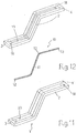
- the thermal conducting body 10 is connected removably (see examples of figures 1-4 , figures 5 and 8 ) to the electrically conducting body 2 so as to make it possible replacing it with an equivalent body, if necessary; or the body 10 can be coupled to the body 2 in a definitive manner, that is not separable anymore, unless through destructive interventions of the device 1, such as, for example, illustrated in figures 6-7 , 11-12 , wherein the thermal conducting body 10 is completely embedded inside the electrically conducting body 2.
- the body 2 is constituted by two shaped rigid bus bars that are electromechanically coupled to each other, for example screwed together (see figures 3 and 4 ); in turn, the thermal conducting body 10 comprises at least one hermetically-sealed hollow tubular element 12, preferably, a plurality of hermetically-sealed hollow tubular elements 12 that run parallel to each other.
- the inside walls of these tubular elements 12 thus constitute surfaces delimiting the respective cavities 11, each of which contains the cooling fluid.
- two suitably shaped plates 13, 14 are further provided, which are also made of thermal conducting material, such as, for example, aluminium or copper.
- the two plates 13 and 14 are arranged at opposite ends of the plurality of tubular elements 12 (in the example illustrated, two) and are appropriately connected to the ends of the tubes themselves 12; in this way, the plates perform a function of structural "binder" among the various tubes 12 and act also as heat collector/diffuser from/to the tubes 12 themselves.
- the thermal conducting body 10 is in this case externally connected, preferably removably, to the electrically conducting body 2; to this end, the plates 13 and 14 are equipped with suitable holes capable of receiving fastening screws-nuts 15, such as those, for example, visible in figures 3 and 4 .
- the body 2 is represented for simplicity sake as constituted by a single block regularly shaped, for example a parallelepiped.
- the thermal conducting body 10 has a structure that is similar to that illustrated in figures 1-4 , thus comprising a plurality of hermetically sealed hollow tubular elements 12, for example three, connected at their opposite ends to the two plates 13 and 14.
- the thermal conducting body 10 is completely embedded inside the electro-conducting body 2.
- Such solution can be made, for example, by "building" the block of the body 2 around the body 10, starting from metallic powders that are consolidated according to metallurgical technologies and processes, which are well known in the art and will not be thereby described in detail.
- co-moulding techniques can be used, related to the powder technology or pouring "casting".
- thermal conducting body 10 does not comprise plates 13 and 14, but comprises only a plurality of hermetically sealed hollow tubular elements 12, embedded inside the block 2.
- the electro-conducting body 2 comprises a sandwich structure having two parts 2A and 2B, mutually coupled in such a way as to define one or more internal seats inside which the thermal conducting body 10 is housed.
- the two parts 2A and 2B which in the example of figures 5 and 8 are also constituted by two parallelepiped blocks, once the body 10 is housed, can be mutually attached definitively, such as, for example, by soldering, or they can be connected in a separable way, if necessary, for example by screwing them, so that with this latter solution the conducting body 10 is removably coupled to the body 2. In practice, if necessary, it would be enough to unscrew the two appropriately prearranged parts 2A and 2B, and to insert the components forming the body 10.
- the thermal conducting body 10 comprises, for example, a structure similar to that of figure 6 that is housed inside the seat defined by the two parts 2A, 2B ( figure 5 ), or a structure similar to that of figure 7 , namely it comprises one, or preferably a series of, hermetically sealed hollow tubular elements 12 which are arranged inside one or several seats defined by the semi-blocks 2A, 2B ( figure 8 ).
- the walls of a sealed cavity 11 consist at least partially of surfaces of the electrically conducting body 10; in this case, the body 2 can be made by providing it directly with one or more through channels 16 for example, by means of drilling or extrusion.
- the thermal conducting body 10 comprises the sealed cavity formed by a through channel 16 along the development of the electro-conducting body 2 and, for each through channel 16, one pair of closing elements 17, such as, for example, plugs made of sealing material. It is to be noted that in the solution of figure 9 , the electro-conducting body 2 and the thermal conducting body 10 are substantially structurally coincident.
- each channel 16 (which in this case can be a totally or partially through channel) a hollow tubular element 12 hermetically sealed and containing the cooling fluid can be inserted directly.
- fluids can be added (as thermal conducting pastes or gels), in order to optimize thermal conduction, particularly with regard to the ends of the thermal conducting body 10 or of the plates 13, 14.
- thermo-conducting body 10 comprises at least one hermetically sealed hollow tubular element 12 shaped, for example, so as to replicate the pattern of the seat 19.
- the tubular element is inserted inside the seat 19 and sealed, for example by means of brazing using, for example, a metal-based paste 20.
- a brazing alloy characterized by a melting point that is low enough to enable brazing without damaging the tubular element 12, but high enough to resist once the device 1 is used in the electrical equipment, is used preferably as the sealing element.
- an alloy of tin and bismuth in variable proportions, but with a prevalence of tin can be used.
- the body 2 is provided with transverse holes 18 suitable for receiving means for connecting with the terminal of a circuit breaker and with a conductor element of the associated electric line.
- the device 1 combines the element 2 used for electrically connecting the circuit breaker to the line, with a cooling device 10 that has: a warmer section that is placed in proximity to the terminals of the circuit breaker that are placed in direct contact with the real breaking part inside the circuit breaker, that is with the part of the circuit breaker that can reach the highest temperatures; and a "cooler" section separated from the warmer section that can be found at any point of the electrical connection, preferably towards an area of the body 2 connecting to the elements of the electric line.
- the warmer section acts as an evaporator for the cooling fluid placed inside the sealed cavity, while the cooler section acts as a condenser; basically, a "thermal short circuit" is achieved between the two sections of the electrical chain characterized by very different temperatures, wherein the device 10 absorbs heat at its warmer section (the circuit breaker terminals), transferring it towards the cooler section such that it is then further transferred to the areas in contact with it (towards the electric line).
- the device 1 has a simple structure that can be quickly and effectively installed in a low voltage system without the need for special prearrangements, and can be sold as a kit for application to any type of switching device that would require its usage.
- the device 1 designed in this way is perfectly adaptable to either fixed, extractable, or removable-type circuit breakers.
- the device 1 is applied, preferably directly, between terminals 21 of the circuit breaker and the bus bars of the electrical system.
- the device 1 can be applied to the intermediate bus bars that connect the switch terminals to the conductors, for example, plug-in couplings (plug-socket) of an adapter (e.g. figures 4 and 13 ), or downstream of the adapter, between the terminals of the adapter and the bus bar system of the electric line.
- plug-in couplings plug-socket
- FIG 4 a circuit breaker 20 in a withdrawable execution is illustrated, which comprises an intermediate adapter 30 and an adapter 40 for an electrical switchboard.
- the switchboard adapter 40 comprises on the internal surface of its bottom wall, a series of connection elements 23 for connection (also here direct or indirect) to the corresponding terminals 21 of the circuit breaker, and on the external part, a series of connection terminals 24 for connection to the electric line, such as, for example, to a system of shaped bus bars.
- each device 1 can be connected to the terminal 24 from on side and, to the corresponding bus bar 50 (or interposed element) from the other side, as illustrated in figure 13 , wherein the tubular elements 12 are schematically indicated by dashed lines.
- another object of the present invention is constituted by an electrical switching device, in particular low voltage circuit breaker, be it in a fixed, removable, or withdrawable execution, having a pair of mutually separable/couplable contacts for opening/closing an associated electric line, and a plurality of input and output connection terminals with said electric line, characterized in that it comprises at least one device 1, according to what described and defined in the appended claims.
- a device 1 allows to have a circuit breaker with a rating higher than an identical circuit breaker which is not provided with such a device 1.
- a device can be commercially sold as a complete circuit breaker (fixed execution) or as part of a withdrawable or removable circuit breaker, mainly comprising the withdrawable or removable breaking part that will then be coupled with a fixed part, whether equipped or not with adapters of the type indicated by 30, 40.
- an electrical switchboard comprising a circuit breaker having a plurality of terminals for input and output electrical connection with an electric line, characterized in that it comprises at least one device 1 for connecting said electric line to one of said terminals as previously described and as defined in the appended claims. In this manner, greater electrical power is drawn compared to what normally is estimated for the cubicle of a known switchboard, so as to be able of having extremely compact, efficient and high-energy efficiency equipment solutions.
- the device 1 thus conceived is susceptible to numerous changes and variants, all of which are in the scope of the inventive concept; additionally, all details can be replaced by other equivalent technical elements.
- the number of tubular elements as well as their configuration, e.g. rectilinear, curved, or mixed can be varied; the plates can be replaced by other elements, such as clamps or tie-rods, thermal conducting paste or gel can be used for increasing efficiency; or the body 2 can be shaped/dimensioned in an entirely different manner such as, for example, with sections stepped, curved, etc.
- the materials, as well as the dimensions can be of any kind depending on the requirements and state of the art.
Description
- The present invention relates to a device for connecting an electric line to a connection terminal with a circuit breaker, and in particular to a connection device that in addition to enabling the electrical connection of the circuit breaker to an electric line, makes it possible to extract heat from the circuit breaker and transfer it to the electric line itself.
- As known, low voltage breaking devices (that is for applications with nominal voltages up to 1000V AC / 1500V DC), such as automatic circuit breakers, disconnectors, and contactors, commonly referred to as "switching devices" and hereinafter collectively referred to as circuit breakers, are devices designed for allowing correct operation of specific parts of electrical systems and installed loads.
- Such devices are usually installed inside distribution switchboards located in electrical systems. Distribution switchboards normally comprise suitable cells or cubicles arranged for connecting the devices to the electrical power distribution lines.
- Distribution lines are normally constituted by systems of conductors, such as bus bars and/or cables. The use of appropriate distribution switchboards, in addition to improving practicality, ergonomics of use, and the aesthetic appearance of the systems, contributes to maintain over time adequate safety conditions and correct functionality of all installed parts.
- The choice of the devices to be used and their installation methods thereof, should be compatible with the technical characteristics of the distribution switchboard. This compatibility relates to electrical, dimensional, mechanical, and thermal aspects. For circuit breakers, there are three main installation configurations in the switchboards.
- In particular, a first installation method for circuit breakers is the so-called "fixed" execution wherein the electrical terminals of the circuit breaker are directly and stably connected to the conductors of the distribution lines. Such connection is normally done by using clamps or screws.
- A second installation method for circuit breakers is the so-called plug-in execution wherein special adapter devices are used which are mechanically connected to the switchboard, and connected stably to the conductors of the distribution lines by means of their own electrical terminals; each circuit breaker is mechanically coupled to a corresponding adapter device and by means of appropriate plug-in electrical terminals, it realizes the electrical connection to the distribution line; plug-in coupling normally includes plug-socket type mechanisms.
- A third installation method for the circuit breakers is the so-called withdrawable execution; it is substantially an evolution of the preceding removable method, wherein accessory elements are added such as guide and/or support and/or movement means for facilitating plugging and withdrawal operations of the circuit breaker.
- Of these three installation methods, the first one is the simplest and cheapest, but it is only suitable to definitive solutions and in any case non-flexible; on the other hand, the removable and withdrawable-type methods offer a greater flexibility. These in fact allow - once the adapter is secured in the switchboard - very quick and totally safe installation or removal of the circuit breaker and, above all, without having to intervene directly on the distribution line.
- Installations of circuit breakers of the removable and withdrawable-type do have at least one disadvantage with regard to the fixed-type installation. In order to realize plug-in junction (plug/socket), it is in fact necessary to introduce at least one additional electrical connector element. Considering the assembly composed by the circuit breaker and its related adapter, it is in fact possible to schematize each of its poles or branches as an electrical chain consisting of elements mutually placed in series. In such electrical chain, each element contributes to increase the electrical resistance (or analogously deteriorate the overall conductivity) and thus constitutes a potential source of heat due to the Joule effect.
- The undesired heat is generated both in the various conducting sections (for example made of copper) and, above all, at each of the present electrical couplings. The various junctions present, and in particular the plug/socket plugs and the main contacts of the circuit breaker, which by their nature cannot be soldered, in fact introduce similar micro-discontinuities where conspicuous localized increases of electrical resistance can be found. In practice, the most critical energy dispersion peaks due to the Joule effect, with consequent undesirable heat production, tend to occur in these areas.
- As can be seen, the heat that is generated due to these dispersions contributes to increase the temperature of the system consisting of circuit breaker, cubicle and switchboard. But since the temperature of the circuit breaker and the temperature of the switchboard should be maintained within predefined operating limits, any undesired increase of electrical resistance in the conducting branches of the system consisting of the circuit breaker and its related adapter compels limiting the power that can be drawn by an apparatus. In addition, the temperature can negatively influence the operation of the circuit breakers. It is likewise known that the temperature of the circuit breaker tends to increase more rapidly if the characteristics of the used adapter, of the cubicle, and of the switchboard favor the accumulation of heat. In practice, with appropriate computations, it is possible to define the maximum fraction of full theoretical load at which a circuit breaker can function in safe condition when it is installed in the cubicle of a switchboard. The fraction of the actually usable maximum load (with respect to the theoretical nominal capacity) is generally expressed in the form of "derating" coefficients that are based on the overall effective conditions of installation. These installation conditions take account of the combination of the characteristics of circuit breaker, adapters, cubicle, switchboard, external environment, etc.
- Besides the constraints associated with derating, it is therefore desirable to maintain the operating temperature of the circuit breakers at low levels; it is well known in fact that the higher is the operating temperature, the lower is the life span of the circuit breaker or of its more sensitive components.
- Many solutions have been introduced by various manufacturers in order to reduce the electrical resistance of the poles of the circuit breakers and the electrical contact resistance of the electrical coupling between the circuit breaker and the adapter, and/or in order to improve the overall thermal efficiency of the switchboard.
- For example, patent
US 3,662,137 discloses a switchgear having heat pipes incorporated in the disconnecting structures and power conductors, according to the preamble ofclaim 1. - Although these well-known solutions certainly provide some technical benefits, there is room and necessity for further improvements.
- Therefore, the main object of this invention is to face these problems and to provide a solution that makes it possible to improve the cooling of the circuit breaker, as well as the electrical switchboard overall inside which the circuit breaker is inserted.
- This object is achieved by way of a device for connecting an electric line to a connection terminal for connection with a circuit breaker, comprising:
- at least one first electrically conducting body having a first end portion intended to be operatively connected to said terminal, and a second end portion intended to be operatively connected to a conductor element of said electric line;
- at least one thermal conducting body comprising a hermetically sealed cavity containing a cooling fluid, said at least one thermal conducting body being operatively coupled to said at least one first electrically conducting body such that said hermetically sealed cavity has a first surface arranged in proximity to said first end portion and a second surface arranged in proximity to said second end portion, characterized in that said at least one thermal conducting body is connected externally to the first electrically conducting body, and in that said at least one thermal conducting body comprises a plurality of hermetically-sealed hollow tubular elements, said hollow tubular elements running parallel to each other with their inside walls delimiting respective cavities containing said cooling fluid, and wherein said at least one thermal conducting body further comprises a first plate and a second plate which are arranged at and connected to opposite ends of said plurality of tubular elements.
- Further characteristics and advantages will become more apparent from the description of some preferred but not exclusive embodiments of the device according to the
invention, illustrated only by way of non-limiting examples with the aid of the accompanying drawings, wherein: -
Figure 1 is a perspective view representing a first embodiment of the connection device according to the invention; -
Figure 2 is an exploded view of the device illustrated infigure 1 ; -
Figure 3 is a perspective view representing a low-voltage circuit breaker connected to a series of contact clips by means of a plurality of devices of the type illustrated infigures 1 and 2 ; -
Figure 4 is an exploded perspective view representing an interruption device of the withdrawable-type in the assembly phase inside an intermediate adapter (retrofit kit) and inside adapter for an electrical switchboard with connection devices of the type illustrated infigures 1-2 ; -
Figures 5-10 are perspective schematic views of possible embodiments of the connection device not forming part of the invention; -
Figure 11 is a perspective view representing a further embodiment of the connection device according to the invention; -
Figure 12 is an exploded view of the device illustrated infigure 11 ; -
Figure 13 is a perspective view representing the device according to the invention connected between an adapter for an electrical switchboard of the type offigure 4 and a bus bar system of an electric line. - In the following description specific reference will be made to the use of the connection device according to the invention for connecting an electric line to one or more terminals of a circuit breaker, without intending in any way to limit its scope of application to other electrical switching or breaking devices; by the definition of circuit breaker it is to be understood any electrical breaking or switching device that is capable of passing from an open state to a closed state (and vice versa) and of breaking/restoring the current flow in an electrical circuit associated with it; such device can be constituted, for example, but not limited to, by a disconnector, or contactor, or an automatic switch (circuit breaker), namely a switching device designed ad hoc to intervene in the presence of significant electrical failure, etc.
- In addition, in the following description reference will be made to the connection of a single terminal of the circuit breaker to a corresponding conductor element of the associated electric line; this description is clearly to be understood to be applicable in entirely analogous manner to all terminals of the circuit breaker and related conductor elements of the electric line.
- With reference to the listed figures, the connection device according to the invention, indicated overall by
reference number 1, comprises at least onefirst body 2, which is made of an electrically conducting material, for example, copper or aluminium, and has at least onefirst end portion 3 and asecond end portion 4. - The
first portion 3 is intended in the installation phase to be connected to acircuit breaker 20, particularly to one of theterminals 21 thecircuit breaker 20 is equipped with for input and output electrical connection with an associated electric line. - In turn, the
second end portion 4 is intended to be connected to a conductor element of the electric line, such as one ormore bus bars 50, as illustrated for example infigure 13 . In the example illustrated infigures 1-4 , theend portion 4 comprises aclip 22 for the connection towards the electric line, for example, with corresponding conductors, indicated infigure 4 byreference number 23; obviously, thisportion 4 can be configured in an entirely different manner according to the specific application (for example fixed, withdrawable, or removable). - Furthermore, it should be understood that the
end portion 3 can be connected directly to aterminal 21 of a circuit breaker, as illustrated infigure 4 , or by means of interpositioning one or more electrically conducting elements, such as, for example, cables, bus bars, etc.; similarly, the electrical chain downstream of theportion 4 can also comprise one or more interconnected electrically conducting elements. - Advantageously, the
device 1 comprises at least one thermal conducting body overall indicated byreference number 10, which can also be made for example of copper, ceramic, or aluminium, or combinations thereof, or any other commercially available material suitable for this purpose and which comprises a hermetically sealedcavity 11 which contains a cooling fluid; preferably, thecavity 11 comprises a small quantity of vaporizable liquid, for example water. - Preferably, the walls of the sealed
cavity 11 have porous, rough, or ribbed internal surfaces. - The thermal conducting
body 10 is operatively coupled to the electrically conductingbody 2 such that the hermetically sealed cavity has a first thermal exchange surface arranged in proximity to thefirst end portion 3 of thebody 2 so as to absorb (directly or indirectly) heat produced by theterminal 21 of thecircuit breaker 20, and a second thermal exchange surface, separated from the first surface, that is arranged in proximity to thesecond end portion 4 so as to transmit heat (directly or indirectly) towards the conductor element of the electric line. - According to the specific requirements and applications, both the electrically conducting
body 2 and the thermal conductingbody 10 can be variously shaped and can each be composed of a single component or of several separate and interconnected components. Also, the mutual connection between the various components of thedevice 1 can vary depending on the applications. In fact, thedevice 1 can be advantageously used both in new installations, wherein the relative position between connection points to the electric line and the terminals of the circuit breaker, can be defined in the design phase thus allowing to provide the components of thedevice 1 with an embodiment as simple as possible, for example, with a rectilinear development, or in retrofit applications, wherein i.e. it is to be incorporated into pre-existing installations, by replacing an obsolete circuit breaker with a new one having a totally different size. In these cases, the connection path imposed can be tortuous and therefore theconnection device 1 also has components having a geometric configuration adapted to the specific case. - In particular, according to one possible embodiment (example of
figures 1-4 ), the thermal conductingbody 10 is connected externally to the electrically conductingbody 2. - Alternatively, the thermal conducting
body 10 is operatively coupled to the electrically conductingbody 2 with the hermetically sealedcavity 11 arranged at least partially inside the electrically conducting body itself. - According to another embodiment, not part of the invention, the thermal conducting
body 2 is arranged completely inside the electrically conducting body 2 (see the examples offigures 5-8 ). - In addition, the thermal conducting
body 10 is connected removably (see examples offigures 1-4 ,figures 5 and8 ) to the electrically conductingbody 2 so as to make it possible replacing it with an equivalent body, if necessary; or thebody 10 can be coupled to thebody 2 in a definitive manner, that is not separable anymore, unless through destructive interventions of thedevice 1, such as, for example, illustrated infigures 6-7 ,11-12 , wherein the thermal conductingbody 10 is completely embedded inside the electrically conductingbody 2. - Now, referring particularly to the embodiment illustrated in
figures 1-4 , thebody 2 is constituted by two shaped rigid bus bars that are electromechanically coupled to each other, for example screwed together (seefigures 3 and4 ); in turn, the thermal conductingbody 10 comprises at least one hermetically-sealed hollowtubular element 12, preferably, a plurality of hermetically-sealed hollowtubular elements 12 that run parallel to each other. The inside walls of thesetubular elements 12 thus constitute surfaces delimiting therespective cavities 11, each of which contains the cooling fluid. In this example embodiment, two suitably shapedplates plates various tubes 12 and act also as heat collector/diffuser from/to thetubes 12 themselves. Thethermal conducting body 10 is in this case externally connected, preferably removably, to the electrically conductingbody 2; to this end, theplates nuts 15, such as those, for example, visible infigures 3 and4 . - In the embodiments illustrated schematically in
figures 6 ,7 ,9 and10 , thebody 2 is represented for simplicity sake as constituted by a single block regularly shaped, for example a parallelepiped. - In turn, in the example of
figure 6 , the thermal conductingbody 10 has a structure that is similar to that illustrated infigures 1-4 , thus comprising a plurality of hermetically sealed hollowtubular elements 12, for example three, connected at their opposite ends to the twoplates body 10 is completely embedded inside the electro-conductingbody 2. Such solution can be made, for example, by "building" the block of thebody 2 around thebody 10, starting from metallic powders that are consolidated according to metallurgical technologies and processes, which are well known in the art and will not be thereby described in detail. For example, co-moulding techniques can be used, related to the powder technology or pouring "casting". - A similar solution is represented in the embodiment example of
figure 7 wherein, unlike the example offigure 6 , the thermal conductingbody 10 does not compriseplates tubular elements 12, embedded inside theblock 2. - In the exemplary embodiments illustrated schematically in
figures 5 and8 , the electro-conductingbody 2 comprises a sandwich structure having twoparts body 10 is housed. The twoparts figures 5 and8 are also constituted by two parallelepiped blocks, once thebody 10 is housed, can be mutually attached definitively, such as, for example, by soldering, or they can be connected in a separable way, if necessary, for example by screwing them, so that with this latter solution the conductingbody 10 is removably coupled to thebody 2. In practice, if necessary, it would be enough to unscrew the two appropriately prearrangedparts body 10. - In turn, the thermal conducting
body 10 comprises, for example, a structure similar to that offigure 6 that is housed inside the seat defined by the twoparts figure 5 ), or a structure similar to that offigure 7 , namely it comprises one, or preferably a series of, hermetically sealed hollowtubular elements 12 which are arranged inside one or several seats defined by thesemi-blocks figure 8 ). - In another embodiment illustrated in
figures 9 and10 , the walls of a sealedcavity 11 consist at least partially of surfaces of the electrically conductingbody 10; in this case, thebody 2 can be made by providing it directly with one or more throughchannels 16 for example, by means of drilling or extrusion. In this example, hence, the thermal conductingbody 10 comprises the sealed cavity formed by a throughchannel 16 along the development of the electro-conductingbody 2 and, for each throughchannel 16, one pair of closingelements 17, such as, for example, plugs made of sealing material. It is to be noted that in the solution offigure 9 , the electro-conductingbody 2 and the thermal conductingbody 10 are substantially structurally coincident. - Alternatively, on the inside of each channel 16 (which in this case can be a totally or partially through channel) a hollow
tubular element 12 hermetically sealed and containing the cooling fluid can be inserted directly. - In this case and in all solutions wherein the electro-conducting
body 2 and the thermal conductingbody 10 are held in contact with mechanical means, at the time of assembly, fluids can be added (as thermal conducting pastes or gels), in order to optimize thermal conduction, particularly with regard to the ends of the thermal conductingbody 10 or of theplates - In another preferred embodiment illustrated in
figures 11 and 12 , aseat 19 open to the external surface of the appropriately configuredbody 2 itself is obtained, for example, by milling. In this case, the thermo-conductingbody 10 comprises at least one hermetically sealed hollowtubular element 12 shaped, for example, so as to replicate the pattern of theseat 19. The tubular element is inserted inside theseat 19 and sealed, for example by means of brazing using, for example, a metal-basedpaste 20. In particular, a brazing alloy, characterized by a melting point that is low enough to enable brazing without damaging thetubular element 12, but high enough to resist once thedevice 1 is used in the electrical equipment, is used preferably as the sealing element. For example, in order to obtain melting points between 140°C and 270°C, an alloy of tin and bismuth in variable proportions, but with a prevalence of tin, can be used. - After brazing by casting, for example, grinding can be performed to eliminate any stocks. In this way, a clean external surface can be obtained with the tubular element completely embedded in the
seat 19 and covered by a sealing. - Finally, also in the various schematic shapes of
figures 5-12 , thebody 2 is provided withtransverse holes 18 suitable for receiving means for connecting with the terminal of a circuit breaker and with a conductor element of the associated electric line. - It has been observed in practice, how the
device 1 according to the invention allows to accomplish the intended scope by providing several significant improvements with regard to known solutions. In fact, thedevice 1 combines theelement 2 used for electrically connecting the circuit breaker to the line, with acooling device 10 that has: a warmer section that is placed in proximity to the terminals of the circuit breaker that are placed in direct contact with the real breaking part inside the circuit breaker, that is with the part of the circuit breaker that can reach the highest temperatures; and a "cooler" section separated from the warmer section that can be found at any point of the electrical connection, preferably towards an area of thebody 2 connecting to the elements of the electric line. In practice, the warmer section acts as an evaporator for the cooling fluid placed inside the sealed cavity, while the cooler section acts as a condenser; basically, a "thermal short circuit" is achieved between the two sections of the electrical chain characterized by very different temperatures, wherein thedevice 10 absorbs heat at its warmer section (the circuit breaker terminals), transferring it towards the cooler section such that it is then further transferred to the areas in contact with it (towards the electric line). - For example, simulating that the temperature of the operating terminals is initially T1 (terminals) = 130°C and that the temperature at the connection area with the line, is T2=100°C, by equipping the connectors of each terminal (upper and lower) with two tubular elements having a diameter of 6mm (a total of 12 tubes), an approximate extractable power of each heat pipe = 15W could be achieved and thus the total extractable power would be equal to 180W. As a result, the temperature of the terminals would be T1 (terminals) = 105°C, while the temperature at the second connection area (cold area towards the electric line) would remain substantially unchanged, because in that area the thermal capacity of the system is very high compared to the modest amount of heat extracted.
- In addition, it should be noted that the
device 1 has a simple structure that can be quickly and effectively installed in a low voltage system without the need for special prearrangements, and can be sold as a kit for application to any type of switching device that would require its usage. - In particular, the
device 1 designed in this way is perfectly adaptable to either fixed, extractable, or removable-type circuit breakers. In the application with fixed circuit breakers, thedevice 1 is applied, preferably directly, betweenterminals 21 of the circuit breaker and the bus bars of the electrical system. - In applications of the removable or withdrawable types the
device 1 can be applied to the intermediate bus bars that connect the switch terminals to the conductors, for example, plug-in couplings (plug-socket) of an adapter (e.g.figures 4 and13 ), or downstream of the adapter, between the terminals of the adapter and the bus bar system of the electric line. For example, infigure 4 acircuit breaker 20 in a withdrawable execution is illustrated, which comprises anintermediate adapter 30 and anadapter 40 for an electrical switchboard. Theswitchboard adapter 40 comprises on the internal surface of its bottom wall, a series ofconnection elements 23 for connection (also here direct or indirect) to thecorresponding terminals 21 of the circuit breaker, and on the external part, a series ofconnection terminals 24 for connection to the electric line, such as, for example, to a system of shaped bus bars. In this case, eachdevice 1 can be connected to the terminal 24 from on side and, to the corresponding bus bar 50 (or interposed element) from the other side, as illustrated infigure 13 , wherein thetubular elements 12 are schematically indicated by dashed lines. - Hence, another object of the present invention is constituted by an electrical switching device, in particular low voltage circuit breaker, be it in a fixed, removable, or withdrawable execution, having a pair of mutually separable/couplable contacts for opening/closing an associated electric line, and a plurality of input and output connection terminals with said electric line, characterized in that it comprises at least one
device 1, according to what described and defined in the appended claims. - In this way, all conditions being equal, the use of a
device 1 allows to have a circuit breaker with a rating higher than an identical circuit breaker which is not provided with such adevice 1. Obviously, such device can be commercially sold as a complete circuit breaker (fixed execution) or as part of a withdrawable or removable circuit breaker, mainly comprising the withdrawable or removable breaking part that will then be coupled with a fixed part, whether equipped or not with adapters of the type indicated by 30, 40. - In addition,
such device 1 can be used together with a circuit breaker for application in any type of electrical switchboard such as, for example, in retrofitting operations, or can be installed inside a switchboard by simply combining it with an already existing circuit breaker for connecting it to an associated electric line, and can be installed indifferently in a distribution bus bar system having a horizontal- or vertical-development. Therefore, another object of the present invention is an electrical switchboard comprising a circuit breaker having a plurality of terminals for input and output electrical connection with an electric line, characterized in that it comprises at least onedevice 1 for connecting said electric line to one of said terminals as previously described and as defined in the appended claims. In this manner, greater electrical power is drawn compared to what normally is estimated for the cubicle of a known switchboard, so as to be able of having extremely compact, efficient and high-energy efficiency equipment solutions. - The
device 1 thus conceived is susceptible to numerous changes and variants, all of which are in the scope of the inventive concept; additionally, all details can be replaced by other equivalent technical elements. For example, the number of tubular elements as well as their configuration, e.g. rectilinear, curved, or mixed can be varied; the plates can be replaced by other elements, such as clamps or tie-rods, thermal conducting paste or gel can be used for increasing efficiency; or thebody 2 can be shaped/dimensioned in an entirely different manner such as, for example, with sections stepped, curved, etc. Further, it is possible to perform any combination of the illustrative examples previously described. In practice, the materials, as well as the dimensions, can be of any kind depending on the requirements and state of the art.
Claims (4)
- A device (1) for connecting an electric line to a connection terminal (21) for connection with a circuit breaker (20), comprising:at least one first electrically conducting body (2) having a first end portion (3) intended to be operatively connected to said terminal (21), and a second end portion (4) intended to be operatively connected to a conductor element (50) of said electric line;at least one thermal conducting body (10) comprising a hermetically sealed cavity (11) containing a cooling fluid, said at least one thermal conducting body (10) being operatively coupled to said at least one first electrically conducting body (2) such that said hermetically sealed cavity (11) has a first surface arranged in proximity to said first end portion (3) and a second surface arranged in proximity to said second end portion (4), characterized in that said at least one thermal conducting body (10) is connected externally to the first electrically conducting body (2), and in that said at least one thermal conducting body (10) comprises a plurality of hermetically-sealed hollow tubular elements (12), said hollow tubular elements (12) running parallel to each other with their inside walls delimiting respective cavities (11) containing said cooling fluid, and wherein said at least one thermal conducting body (10) further comprises a first plate (13) and a second plate (14) which are arranged at and connected to opposite ends of said plurality of tubular elements (12).
- A device (1) according to claim 1, wherein said at least one thermal conducting body (10) is removably connected to the first electrically conducting body (2).
- An electrical switchboard comprising a circuit breaker (20) having a plurality of terminals (21) for input and output electrical connection with an electric line, wherein it comprises at least one device (1) for connecting said electric line to one of said terminals (21) according to one or more of the preceding claims.
- An electrical switching device (20) having a pair of mutually separable/couplable contacts for opening/closing an associated electric line, and a plurality of input and output connection terminals (21) with said electric line, wherein it comprises at least one connection device (1) according to one or more of claims 1-2.
Applications Claiming Priority (1)
| Application Number | Priority Date | Filing Date | Title |
|---|---|---|---|
| IT000030A ITBG20090030A1 (en) | 2009-05-28 | 2009-05-28 | DEVICE FOR THE CONNECTION OF AN ELECTRIC LINE TO A SWITCH. |
Publications (3)
| Publication Number | Publication Date |
|---|---|
| EP2256767A2 EP2256767A2 (en) | 2010-12-01 |
| EP2256767A3 EP2256767A3 (en) | 2012-08-29 |
| EP2256767B1 true EP2256767B1 (en) | 2016-08-24 |
Family
ID=41308980
Family Applications (1)
| Application Number | Title | Priority Date | Filing Date |
|---|---|---|---|
| EP10160990.7A Active EP2256767B1 (en) | 2009-05-28 | 2010-04-26 | Heatpipe for terminal of circuit breaker |
Country Status (6)
| Country | Link |
|---|---|
| US (1) | US8339773B2 (en) |
| EP (1) | EP2256767B1 (en) |
| CN (1) | CN101901725B (en) |
| BR (1) | BRPI1001574B1 (en) |
| ES (1) | ES2603223T3 (en) |
| IT (1) | ITBG20090030A1 (en) |
Cited By (1)
| Publication number | Priority date | Publication date | Assignee | Title |
|---|---|---|---|---|
| US11842877B2 (en) | 2021-01-27 | 2023-12-12 | Abb Schweiz Ag | Electric pole part apparatus |
Families Citing this family (23)
| Publication number | Priority date | Publication date | Assignee | Title |
|---|---|---|---|---|
| US9172167B2 (en) * | 2004-11-20 | 2015-10-27 | Al Cop Llc | Junction failure inhibiting connector |
| EP2277365B1 (en) * | 2008-05-16 | 2011-11-02 | Parker-Hannifin Corporation | Modular high-power drive stack cooled with vaporizable dielectric fluid |
| JP5084910B2 (en) * | 2008-09-11 | 2012-11-28 | 三菱電機株式会社 | Gas insulated switchgear |
| DE102009022105A1 (en) * | 2009-05-20 | 2010-11-25 | Abb Technology Ag | Gas-insulated high-voltage switchgear |
| US8695358B2 (en) * | 2011-05-23 | 2014-04-15 | Abb Research Ltd. | Switchgear having evaporative cooling apparatus |
| US8717746B2 (en) * | 2012-03-22 | 2014-05-06 | Abb Technology Ag | Cooling apparatus for switchgear with enhanced busbar joint cooling |
| EP2828872B1 (en) * | 2012-03-22 | 2018-05-16 | ABB Schweiz AG | Cooling apparatus for switchgear with heat pipe structure having integrated busbar tube |
| CN103456533A (en) * | 2012-05-30 | 2013-12-18 | 沈阳铝镁科技有限公司 | Inner-liquid-cooled type switch piece device |
| WO2014142788A1 (en) * | 2013-03-11 | 2014-09-18 | Schneider Electric USA, Inc. | Self-aligning power connection system with positive-latch connection |
| US9137925B2 (en) * | 2013-05-08 | 2015-09-15 | Hamilton Sundstrand Corporation | Heat sink for contactor in power distribution assembly |
| EP3127201B1 (en) * | 2014-03-31 | 2020-11-18 | Schneider Electric USA, Inc. | Integrated connector for backplane of a draw out breaker chassis |
| JP2016018924A (en) * | 2014-07-09 | 2016-02-01 | 矢崎総業株式会社 | Heat dissipation structure of semiconductor breaker |
| EP2983261A1 (en) * | 2014-08-04 | 2016-02-10 | ABB Technology AG | Bus bar with integrated heat pipe |
| WO2016176204A1 (en) * | 2015-04-27 | 2016-11-03 | Abb Technology Ag | Modular electrical devices and methods for assembling and mounting the same |
| US9493083B1 (en) * | 2015-06-22 | 2016-11-15 | Delphi Technologies, Inc. | Electrical plug adapter |
| US10292310B2 (en) * | 2016-12-22 | 2019-05-14 | Eaton Intelligent Power Limited | Thermally conductive assemblies with wedge blocks for contact heat conduction suitable for electrical devices such as load centers |
| WO2019197042A1 (en) * | 2018-04-13 | 2019-10-17 | Abb Schweiz Ag | Arrangement for connecting a circuit breaker to a conducting layer of a laminated busbar and switchgear comprising such an arrangement |
| US11355902B2 (en) * | 2019-01-28 | 2022-06-07 | TE Connectivity Services Gmbh | Power connector for a bus bar |
| EP3742461B1 (en) | 2019-05-20 | 2022-02-23 | ABB Schweiz AG | Cooling apparatus for a medium voltage or high voltage switchgear |
| JP2021086907A (en) * | 2019-11-27 | 2021-06-03 | ナブテスコ株式会社 | Electronic apparatus for aircraft |
| US11158998B1 (en) * | 2020-04-27 | 2021-10-26 | Abb Schweiz Ag | Heat sink for power supply panel |
| CN116321911A (en) * | 2021-12-03 | 2023-06-23 | 泰连服务有限公司 | Coolant system for a busbar assembly |
| US20230411936A1 (en) * | 2022-06-17 | 2023-12-21 | Schneider Electric USA, Inc. | Expander kit for installing small frame circuit breakers in electrical distribution devices designed for large frame circuit breakers |
Family Cites Families (11)
| Publication number | Priority date | Publication date | Assignee | Title |
|---|---|---|---|---|
| US3662137A (en) * | 1970-01-21 | 1972-05-09 | Westinghouse Electric Corp | Switchgear having heat pipes incorporated in the disconnecting structures and power conductors |
| US3728585A (en) * | 1972-06-12 | 1973-04-17 | Gen Electric | Electric switchboard assembly with bus bar heat pipe means |
| US3778680A (en) * | 1972-09-26 | 1973-12-11 | D Vaneerden | High amperage switch apparatus with resiliently mounted fluid cooled terminals |
| US4005297A (en) * | 1972-10-18 | 1977-01-25 | Westinghouse Electric Corporation | Vacuum-type circuit interrupters having heat-dissipating devices associated with the contact structures thereof |
| US4650939A (en) * | 1986-01-24 | 1987-03-17 | Westinghouse Electric Corp. | Vacuum circuit interrupter having heat exchanger for temperature control |
| US4830630A (en) * | 1988-08-22 | 1989-05-16 | Hilliard Dozier | Hermetically sealed electrical terminal |
| JP2004095530A (en) * | 2002-06-20 | 2004-03-25 | Furukawa Electric Co Ltd:The | Tubular bus bar, insulating coating method therefor, and insulating coating structure therefor |
| ITBG20030059A1 (en) * | 2003-12-17 | 2005-06-18 | Abb Service Srl | CONNECTION DEVICE FOR CONDUTTRIC BARS TO APPLIANCES OF AN ELECTRIC PANEL. |
| US6986383B2 (en) * | 2004-03-30 | 2006-01-17 | Hul-Chun Hsu | End surface structure of a heat pipe for contact with a heat source |
| IT1395698B1 (en) * | 2009-05-28 | 2012-10-19 | Abb Spa | COOLING DEVICE FOR A SWITCH, AND SWITCH INCLUDING THIS DEVICE. |
| IT1395697B1 (en) * | 2009-05-28 | 2012-10-19 | Abb Spa | CURRENT TRANSFORMER, PROTECTIVE DEVICE INCLUDING SUCH TRANSFORMER, AND RELATIVE SWITCH |
-
2009
- 2009-05-28 IT IT000030A patent/ITBG20090030A1/en unknown
-
2010
- 2010-04-26 EP EP10160990.7A patent/EP2256767B1/en active Active
- 2010-04-26 ES ES10160990.7T patent/ES2603223T3/en active Active
- 2010-05-27 US US12/788,873 patent/US8339773B2/en active Active
- 2010-05-27 CN CN201010190629.9A patent/CN101901725B/en active Active
- 2010-05-27 BR BRPI1001574-4A patent/BRPI1001574B1/en active IP Right Grant
Cited By (1)
| Publication number | Priority date | Publication date | Assignee | Title |
|---|---|---|---|---|
| US11842877B2 (en) | 2021-01-27 | 2023-12-12 | Abb Schweiz Ag | Electric pole part apparatus |
Also Published As
| Publication number | Publication date |
|---|---|
| US8339773B2 (en) | 2012-12-25 |
| ITBG20090030A1 (en) | 2010-11-29 |
| EP2256767A2 (en) | 2010-12-01 |
| CN101901725B (en) | 2014-09-10 |
| BRPI1001574B1 (en) | 2019-07-02 |
| ES2603223T3 (en) | 2017-02-24 |
| CN101901725A (en) | 2010-12-01 |
| BRPI1001574A2 (en) | 2011-07-26 |
| US20100304590A1 (en) | 2010-12-02 |
| EP2256767A3 (en) | 2012-08-29 |
Similar Documents
| Publication | Publication Date | Title |
|---|---|---|
| EP2256767B1 (en) | Heatpipe for terminal of circuit breaker | |
| US8169775B2 (en) | Cooling device for a circuit breaker and circuit breaker comprising such device | |
| CN104810193A (en) | Main circuit terminal assembly for vacuum circuit breaker | |
| US7909663B1 (en) | Modular optimized plug-in jaw | |
| EP2256757B1 (en) | Current transformer as well as protection device and circuit breaker including such transformer | |
| ITMI20080502A1 (en) | ADAPTER DEVICE FOR A LOW VOLTAGE INTERRUPT DEVICE | |
| US3211960A (en) | Insulating mounting block and circuit interrupting device | |
| KR101097616B1 (en) | Multipurpose case module of gas insulated switchgear | |
| CN206379628U (en) | One kind is used for busbar channel and switch disconnector attachment means in cabinet | |
| EP2405543B1 (en) | Switchgear comprising a slidable circuit-breaker, a transformer and an electrical connector between the two | |
| CN111740728B (en) | Improved withdrawable solid-state switching device | |
| CN106785945B (en) | One kind is for busbar channel in cabinet and switch disconnector attachment device | |
| CN219123894U (en) | Fixing structure of bus duct | |
| CN200987044Y (en) | Rear wire outlet four-pole cable adapter for switch cabinet | |
| WO2023147847A1 (en) | Relay switch | |
| CN201063325Y (en) | Zero sequence mutual inductor penetration-hole coupling conductive device special for creepage breaker | |
| KR101433004B1 (en) | Heat sink busbar and switchgear having thereof | |
| JP2021515360A (en) | Circuit breaker housing | |
| KR20120007659U (en) | Contact apparatus for gas insulated switchgear |
Legal Events
| Date | Code | Title | Description |
|---|---|---|---|
| PUAI | Public reference made under article 153(3) epc to a published international application that has entered the european phase |
Free format text: ORIGINAL CODE: 0009012 |
|
| AK | Designated contracting states |
Kind code of ref document: A2 Designated state(s): AT BE BG CH CY CZ DE DK EE ES FI FR GB GR HR HU IE IS IT LI LT LU LV MC MK MT NL NO PL PT RO SE SI SK SM TR |
|
| AX | Request for extension of the european patent |
Extension state: AL BA ME RS |
|
| PUAL | Search report despatched |
Free format text: ORIGINAL CODE: 0009013 |
|
| AK | Designated contracting states |
Kind code of ref document: A3 Designated state(s): AT BE BG CH CY CZ DE DK EE ES FI FR GB GR HR HU IE IS IT LI LT LU LV MC MK MT NL NO PL PT RO SE SI SK SM TR |
|
| AX | Request for extension of the european patent |
Extension state: AL BA ME RS |
|
| RIC1 | Information provided on ipc code assigned before grant |
Ipc: H01H 1/58 20060101AFI20120726BHEP Ipc: H01H 9/52 20060101ALI20120726BHEP Ipc: H02B 11/12 20060101ALI20120726BHEP |
|
| 17P | Request for examination filed |
Effective date: 20130227 |
|
| GRAP | Despatch of communication of intention to grant a patent |
Free format text: ORIGINAL CODE: EPIDOSNIGR1 |
|
| RIC1 | Information provided on ipc code assigned before grant |
Ipc: H02B 1/56 20060101ALI20160215BHEP Ipc: H01H 1/58 20060101AFI20160215BHEP Ipc: H02B 11/04 20060101ALI20160215BHEP Ipc: H01H 9/52 20060101ALI20160215BHEP |
|
| INTG | Intention to grant announced |
Effective date: 20160317 |
|
| GRAS | Grant fee paid |
Free format text: ORIGINAL CODE: EPIDOSNIGR3 |
|
| GRAA | (expected) grant |
Free format text: ORIGINAL CODE: 0009210 |
|
| AK | Designated contracting states |
Kind code of ref document: B1 Designated state(s): AT BE BG CH CY CZ DE DK EE ES FI FR GB GR HR HU IE IS IT LI LT LU LV MC MK MT NL NO PL PT RO SE SI SK SM TR |
|
| REG | Reference to a national code |
Ref country code: GB Ref legal event code: FG4D |
|
| REG | Reference to a national code |
Ref country code: CH Ref legal event code: EP |
|
| REG | Reference to a national code |
Ref country code: AT Ref legal event code: REF Ref document number: 823726 Country of ref document: AT Kind code of ref document: T Effective date: 20160915 |
|
| REG | Reference to a national code |
Ref country code: IE Ref legal event code: FG4D |
|
| REG | Reference to a national code |
Ref country code: DE Ref legal event code: R096 Ref document number: 602010035751 Country of ref document: DE |
|
| REG | Reference to a national code |
Ref country code: SE Ref legal event code: TRGR |
|
| REG | Reference to a national code |
Ref country code: LT Ref legal event code: MG4D |
|
| REG | Reference to a national code |
Ref country code: NL Ref legal event code: MP Effective date: 20160824 |
|
| REG | Reference to a national code |
Ref country code: AT Ref legal event code: MK05 Ref document number: 823726 Country of ref document: AT Kind code of ref document: T Effective date: 20160824 |
|
| PG25 | Lapsed in a contracting state [announced via postgrant information from national office to epo] |
Ref country code: FI Free format text: LAPSE BECAUSE OF FAILURE TO SUBMIT A TRANSLATION OF THE DESCRIPTION OR TO PAY THE FEE WITHIN THE PRESCRIBED TIME-LIMIT Effective date: 20160824 Ref country code: LT Free format text: LAPSE BECAUSE OF FAILURE TO SUBMIT A TRANSLATION OF THE DESCRIPTION OR TO PAY THE FEE WITHIN THE PRESCRIBED TIME-LIMIT Effective date: 20160824 Ref country code: NO Free format text: LAPSE BECAUSE OF FAILURE TO SUBMIT A TRANSLATION OF THE DESCRIPTION OR TO PAY THE FEE WITHIN THE PRESCRIBED TIME-LIMIT Effective date: 20161124 Ref country code: HR Free format text: LAPSE BECAUSE OF FAILURE TO SUBMIT A TRANSLATION OF THE DESCRIPTION OR TO PAY THE FEE WITHIN THE PRESCRIBED TIME-LIMIT Effective date: 20160824 Ref country code: NL Free format text: LAPSE BECAUSE OF FAILURE TO SUBMIT A TRANSLATION OF THE DESCRIPTION OR TO PAY THE FEE WITHIN THE PRESCRIBED TIME-LIMIT Effective date: 20160824 |
|
| REG | Reference to a national code |
Ref country code: ES Ref legal event code: FG2A Ref document number: 2603223 Country of ref document: ES Kind code of ref document: T3 Effective date: 20170224 |
|
| PG25 | Lapsed in a contracting state [announced via postgrant information from national office to epo] |
Ref country code: PT Free format text: LAPSE BECAUSE OF FAILURE TO SUBMIT A TRANSLATION OF THE DESCRIPTION OR TO PAY THE FEE WITHIN THE PRESCRIBED TIME-LIMIT Effective date: 20161226 Ref country code: LV Free format text: LAPSE BECAUSE OF FAILURE TO SUBMIT A TRANSLATION OF THE DESCRIPTION OR TO PAY THE FEE WITHIN THE PRESCRIBED TIME-LIMIT Effective date: 20160824 Ref country code: AT Free format text: LAPSE BECAUSE OF FAILURE TO SUBMIT A TRANSLATION OF THE DESCRIPTION OR TO PAY THE FEE WITHIN THE PRESCRIBED TIME-LIMIT Effective date: 20160824 |
|
| REG | Reference to a national code |
Ref country code: GR Ref legal event code: EP Ref document number: 20160402907 Country of ref document: GR Effective date: 20170222 |
|
| REG | Reference to a national code |
Ref country code: FR Ref legal event code: PLFP Year of fee payment: 8 |
|
| PG25 | Lapsed in a contracting state [announced via postgrant information from national office to epo] |
Ref country code: RO Free format text: LAPSE BECAUSE OF FAILURE TO SUBMIT A TRANSLATION OF THE DESCRIPTION OR TO PAY THE FEE WITHIN THE PRESCRIBED TIME-LIMIT Effective date: 20160824 Ref country code: EE Free format text: LAPSE BECAUSE OF FAILURE TO SUBMIT A TRANSLATION OF THE DESCRIPTION OR TO PAY THE FEE WITHIN THE PRESCRIBED TIME-LIMIT Effective date: 20160824 |
|
| REG | Reference to a national code |
Ref country code: DE Ref legal event code: R097 Ref document number: 602010035751 Country of ref document: DE |
|
| PG25 | Lapsed in a contracting state [announced via postgrant information from national office to epo] |
Ref country code: CZ Free format text: LAPSE BECAUSE OF FAILURE TO SUBMIT A TRANSLATION OF THE DESCRIPTION OR TO PAY THE FEE WITHIN THE PRESCRIBED TIME-LIMIT Effective date: 20160824 Ref country code: BE Free format text: LAPSE BECAUSE OF FAILURE TO SUBMIT A TRANSLATION OF THE DESCRIPTION OR TO PAY THE FEE WITHIN THE PRESCRIBED TIME-LIMIT Effective date: 20160824 Ref country code: BG Free format text: LAPSE BECAUSE OF FAILURE TO SUBMIT A TRANSLATION OF THE DESCRIPTION OR TO PAY THE FEE WITHIN THE PRESCRIBED TIME-LIMIT Effective date: 20161124 Ref country code: PL Free format text: LAPSE BECAUSE OF FAILURE TO SUBMIT A TRANSLATION OF THE DESCRIPTION OR TO PAY THE FEE WITHIN THE PRESCRIBED TIME-LIMIT Effective date: 20160824 Ref country code: DK Free format text: LAPSE BECAUSE OF FAILURE TO SUBMIT A TRANSLATION OF THE DESCRIPTION OR TO PAY THE FEE WITHIN THE PRESCRIBED TIME-LIMIT Effective date: 20160824 Ref country code: SM Free format text: LAPSE BECAUSE OF FAILURE TO SUBMIT A TRANSLATION OF THE DESCRIPTION OR TO PAY THE FEE WITHIN THE PRESCRIBED TIME-LIMIT Effective date: 20160824 Ref country code: SK Free format text: LAPSE BECAUSE OF FAILURE TO SUBMIT A TRANSLATION OF THE DESCRIPTION OR TO PAY THE FEE WITHIN THE PRESCRIBED TIME-LIMIT Effective date: 20160824 |
|
| PLBE | No opposition filed within time limit |
Free format text: ORIGINAL CODE: 0009261 |
|
| STAA | Information on the status of an ep patent application or granted ep patent |
Free format text: STATUS: NO OPPOSITION FILED WITHIN TIME LIMIT |
|
| 26N | No opposition filed |
Effective date: 20170526 |
|
| PG25 | Lapsed in a contracting state [announced via postgrant information from national office to epo] |
Ref country code: SI Free format text: LAPSE BECAUSE OF FAILURE TO SUBMIT A TRANSLATION OF THE DESCRIPTION OR TO PAY THE FEE WITHIN THE PRESCRIBED TIME-LIMIT Effective date: 20160824 |
|
| REG | Reference to a national code |
Ref country code: CH Ref legal event code: PL |
|
| REG | Reference to a national code |
Ref country code: IE Ref legal event code: MM4A |
|
| PG25 | Lapsed in a contracting state [announced via postgrant information from national office to epo] |
Ref country code: MC Free format text: LAPSE BECAUSE OF FAILURE TO SUBMIT A TRANSLATION OF THE DESCRIPTION OR TO PAY THE FEE WITHIN THE PRESCRIBED TIME-LIMIT Effective date: 20160824 |
|
| PG25 | Lapsed in a contracting state [announced via postgrant information from national office to epo] |
Ref country code: LI Free format text: LAPSE BECAUSE OF NON-PAYMENT OF DUE FEES Effective date: 20170430 Ref country code: LU Free format text: LAPSE BECAUSE OF NON-PAYMENT OF DUE FEES Effective date: 20170426 Ref country code: CH Free format text: LAPSE BECAUSE OF NON-PAYMENT OF DUE FEES Effective date: 20170430 |
|
| REG | Reference to a national code |
Ref country code: FR Ref legal event code: PLFP Year of fee payment: 9 |
|
| PG25 | Lapsed in a contracting state [announced via postgrant information from national office to epo] |
Ref country code: IE Free format text: LAPSE BECAUSE OF NON-PAYMENT OF DUE FEES Effective date: 20170426 |
|
| PG25 | Lapsed in a contracting state [announced via postgrant information from national office to epo] |
Ref country code: MT Free format text: LAPSE BECAUSE OF NON-PAYMENT OF DUE FEES Effective date: 20170426 |
|
| PG25 | Lapsed in a contracting state [announced via postgrant information from national office to epo] |
Ref country code: HU Free format text: LAPSE BECAUSE OF FAILURE TO SUBMIT A TRANSLATION OF THE DESCRIPTION OR TO PAY THE FEE WITHIN THE PRESCRIBED TIME-LIMIT; INVALID AB INITIO Effective date: 20100426 |
|
| PG25 | Lapsed in a contracting state [announced via postgrant information from national office to epo] |
Ref country code: CY Free format text: LAPSE BECAUSE OF NON-PAYMENT OF DUE FEES Effective date: 20160824 |
|
| PG25 | Lapsed in a contracting state [announced via postgrant information from national office to epo] |
Ref country code: MK Free format text: LAPSE BECAUSE OF FAILURE TO SUBMIT A TRANSLATION OF THE DESCRIPTION OR TO PAY THE FEE WITHIN THE PRESCRIBED TIME-LIMIT Effective date: 20160824 |
|
| PG25 | Lapsed in a contracting state [announced via postgrant information from national office to epo] |
Ref country code: IS Free format text: LAPSE BECAUSE OF FAILURE TO SUBMIT A TRANSLATION OF THE DESCRIPTION OR TO PAY THE FEE WITHIN THE PRESCRIBED TIME-LIMIT Effective date: 20161224 |
|
| PGFP | Annual fee paid to national office [announced via postgrant information from national office to epo] |
Ref country code: IT Payment date: 20230426 Year of fee payment: 14 Ref country code: FR Payment date: 20230425 Year of fee payment: 14 Ref country code: ES Payment date: 20230627 Year of fee payment: 14 Ref country code: DE Payment date: 20230420 Year of fee payment: 14 |
|
| PGFP | Annual fee paid to national office [announced via postgrant information from national office to epo] |
Ref country code: TR Payment date: 20230424 Year of fee payment: 14 Ref country code: SE Payment date: 20230420 Year of fee payment: 14 Ref country code: GR Payment date: 20230420 Year of fee payment: 14 |
|
| PGFP | Annual fee paid to national office [announced via postgrant information from national office to epo] |
Ref country code: GB Payment date: 20230419 Year of fee payment: 14 |