EP2256534A1 - In-vivo examination apparatus - Google Patents
In-vivo examination apparatus Download PDFInfo
- Publication number
- EP2256534A1 EP2256534A1 EP10005576A EP10005576A EP2256534A1 EP 2256534 A1 EP2256534 A1 EP 2256534A1 EP 10005576 A EP10005576 A EP 10005576A EP 10005576 A EP10005576 A EP 10005576A EP 2256534 A1 EP2256534 A1 EP 2256534A1
- Authority
- EP
- European Patent Office
- Prior art keywords
- biological
- image
- micro
- biological specimen
- specimen
- Prior art date
- Legal status (The legal status is an assumption and is not a legal conclusion. Google has not performed a legal analysis and makes no representation as to the accuracy of the status listed.)
- Granted
Links
- 238000001727 in vivo Methods 0.000 title 1
- 230000005284 excitation Effects 0.000 claims abstract description 39
- 238000005286 illumination Methods 0.000 claims abstract description 18
- 239000000284 extract Substances 0.000 claims abstract description 9
- 230000003287 optical effect Effects 0.000 claims description 28
- 230000032823 cell division Effects 0.000 claims description 22
- 230000005855 radiation Effects 0.000 claims description 2
- 238000000034 method Methods 0.000 description 20
- 238000010586 diagram Methods 0.000 description 16
- 230000004048 modification Effects 0.000 description 15
- 238000012986 modification Methods 0.000 description 15
- 230000005484 gravity Effects 0.000 description 8
- 230000008569 process Effects 0.000 description 6
- 210000004027 cell Anatomy 0.000 description 3
- 230000005540 biological transmission Effects 0.000 description 2
- 230000010485 coping Effects 0.000 description 2
- 230000003247 decreasing effect Effects 0.000 description 2
- 230000004075 alteration Effects 0.000 description 1
- 230000008901 benefit Effects 0.000 description 1
- 210000004748 cultured cell Anatomy 0.000 description 1
- 230000007423 decrease Effects 0.000 description 1
- 229910052736 halogen Inorganic materials 0.000 description 1
- 150000002367 halogens Chemical class 0.000 description 1
- 230000007774 longterm Effects 0.000 description 1
- 239000000463 material Substances 0.000 description 1
- 230000007246 mechanism Effects 0.000 description 1
- QSHDDOUJBYECFT-UHFFFAOYSA-N mercury Chemical compound [Hg] QSHDDOUJBYECFT-UHFFFAOYSA-N 0.000 description 1
- 229910052753 mercury Inorganic materials 0.000 description 1
- 244000005700 microbiome Species 0.000 description 1
- 229910052724 xenon Inorganic materials 0.000 description 1
- FHNFHKCVQCLJFQ-UHFFFAOYSA-N xenon atom Chemical compound [Xe] FHNFHKCVQCLJFQ-UHFFFAOYSA-N 0.000 description 1
Images










Classifications
-
- G—PHYSICS
- G02—OPTICS
- G02B—OPTICAL ELEMENTS, SYSTEMS OR APPARATUS
- G02B21/00—Microscopes
- G02B21/36—Microscopes arranged for photographic purposes or projection purposes or digital imaging or video purposes including associated control and data processing arrangements
- G02B21/365—Control or image processing arrangements for digital or video microscopes
- G02B21/367—Control or image processing arrangements for digital or video microscopes providing an output produced by processing a plurality of individual source images, e.g. image tiling, montage, composite images, depth sectioning, image comparison
-
- G—PHYSICS
- G02—OPTICS
- G02B—OPTICAL ELEMENTS, SYSTEMS OR APPARATUS
- G02B21/00—Microscopes
- G02B21/0004—Microscopes specially adapted for specific applications
- G02B21/002—Scanning microscopes
-
- G—PHYSICS
- G02—OPTICS
- G02B—OPTICAL ELEMENTS, SYSTEMS OR APPARATUS
- G02B21/00—Microscopes
- G02B21/0004—Microscopes specially adapted for specific applications
- G02B21/002—Scanning microscopes
- G02B21/0024—Confocal scanning microscopes (CSOMs) or confocal "macroscopes"; Accessories which are not restricted to use with CSOMs, e.g. sample holders
- G02B21/0052—Optical details of the image generation
- G02B21/0072—Optical details of the image generation details concerning resolution or correction, including general design of CSOM objectives
-
- G—PHYSICS
- G02—OPTICS
- G02B—OPTICAL ELEMENTS, SYSTEMS OR APPARATUS
- G02B21/00—Microscopes
- G02B21/0004—Microscopes specially adapted for specific applications
- G02B21/002—Scanning microscopes
- G02B21/0024—Confocal scanning microscopes (CSOMs) or confocal "macroscopes"; Accessories which are not restricted to use with CSOMs, e.g. sample holders
- G02B21/0052—Optical details of the image generation
- G02B21/0076—Optical details of the image generation arrangements using fluorescence or luminescence
-
- G—PHYSICS
- G02—OPTICS
- G02B—OPTICAL ELEMENTS, SYSTEMS OR APPARATUS
- G02B21/00—Microscopes
- G02B21/0004—Microscopes specially adapted for specific applications
- G02B21/002—Scanning microscopes
- G02B21/0024—Confocal scanning microscopes (CSOMs) or confocal "macroscopes"; Accessories which are not restricted to use with CSOMs, e.g. sample holders
- G02B21/008—Details of detection or image processing, including general computer control
Definitions
- the present invention relates to a biological observation apparatus.
- a microscope apparatus disclosed in Japanese Unexamined Patent Application, Publication No. 2008-281720 is configured so as to irradiate a specified biological specimen mounted on a stage with illumination light and to control the stage position, on the basis of image information acquired by capturing its transmitted light, so that the biological specimen does not leave the field of view. It is also configured so as to perform fluorescence observation by capturing fluorescence generated at the biological specimen by radiating excitation light while tracking the movement of the biological specimen.
- the present invention provides a biological observation apparatus that is capable of performing detailed fluorescence observation without losing a biological specimen from the viewing range.
- a first aspect of the present invention is a biological observation apparatus that includes a macro-image acquisition unit that acquires a macro image of an observation region that includes a biological specimen; a micro-image acquisition unit that acquires a micro image of the biological specimen; an identification-information storing unit that stores identification information of the biological specimen; a biological-specimen specifying unit that extracts identification information of the biological specimen included in the macro image by performing image processing on the macro image acquired by the macro-image acquisition unit and that specifies the biological specimen for which the extracted identification information corresponds to the identification information stored in the identification-information storing unit; and an adjuster that adjusts relative positions of the biological specimen and a viewing range of the micro image such that the biological specimen specified by the biological-specimen specifying unit is included in the viewing range of the micro image.
- a large-area observation region can be displayed with a larger field of view than the micro image, whereas, in the micro image, a biological specimen can be displayed at higher resolution than the macro image. Therefore, for the biological specimen specified by the biological-specimen specifying unit on the basis of the identification information stored in the identification-information storing unit, the biological specimen can be kept within the viewing range of the macro image even when the biological specimen has moved.
- the required field of view is several tens of micrometers in length and several tens of micrometers in width
- the identification information of the biological specimen any information that allows the biological specimen to be identified through image processing may be used, examples of which include the position of the center of gravity, shape, size, brightness, etc. of the biological specimen.
- a stage on which the biological specimen is mounted a scanner that scans irradiation light emitted from a light source, and a controller that controls a swing-angle range of the scanner
- the macro-image acquisition unit may acquire the macro image by detecting observation light from the scanning range of the irradiation light scanned in the observation region by the scanner
- the micro-image acquisition unit may acquire the micro image by detecting observation light from the scanning range of irradiation light scanned in the observation region by the scanner
- the controller may control the swing-angle range of the scanner such that the scanning amplitude of the irradiation light becomes smaller when acquiring the micro image than when acquiring the macro image.
- the observation light from the observation region, over which irradiation light is scanned by the scanner is acquired by the macro-image acquisition unit to obtain a macro image of the observation region, and, additionally, the observation light from the biological specimen, over which irradiation light is scanned by the scanner, is detected by the micro-image acquisition unit to obtain a micro image of the biological specimen.
- the scanning amplitude of the irradiation light is increased when acquiring the macro image; in addition, the scanning amplitude of the irradiation light is decreased when acquiring the micro image, and thus, in the macro image, an observation region can be displayed with a field of view of a larger area than the micro image, whereas, in the micro image, a biological specimen can be displayed at higher resolution than the macro image.
- the adjuster may adjust the swing-range position of the scanner such that the biological specimen specified by the biological-specimen specifying unit is included in the viewing range of the micro image.
- the micro image can be easily tracked in accordance with the movement of the biological specimen.
- an objective lens that radiates the irradiation light scanned by the scanner onto the biological specimen may be provided, and the adjuster may adjust relative positions of the objective lens and the stage in a direction that intersects the optical axis such that the biological specimen specified by the biological-specimen specifying unit is included in the viewing range of the micro image.
- the micro image can be tracked in accordance with the movement of the biological specimen over a larger area.
- the macro-image acquisition unit may acquire a three-dimensional macro image of the biological specimen.
- the micro image can be tracked even for three-dimensional movement, etc. of the biological specimen.
- a stage on which the biological specimen is mounted a scanner that scans irradiation light emitted from a light source, and a controller that controls a swing-angle range of the scanner
- the macro-image acquisition unit may acquire the macro image by capturing observation light from an area in the observation region irradiated by the irradiation light emitted from the light source
- the micro-image acquisition unit may acquire the micro image by detecting observation light from the scanning range of the irradiation light scanned in the observation region by the scanner
- the controller may control the swing-angle range of the scanner such that the viewing range for the micro image becomes smaller than the viewing range for the macro image.
- the scanning amplitude of the irradiation light is decreased with respect to the field of view of the macro image when acquiring the micro image, and thereby, in the macro image, an observation region can be displayed with a field of view of a larger area than the micro image, whereas, in the micro image, a biological specimen can be displayed at higher resolution than the macro image.
- the adjuster may adjust the swing-range position of the scanner such that the biological specimen specified by the biological-specimen specifying unit is included in the viewing range of the micro image.
- an objective lens that radiates the irradiation light scanned by the scanner onto the biological specimen may be provided, and the adjuster may adjust relative positions of the objective lens and the stage in the direction that intersects the optical axis such that the biological specimen specified by the biological-specimen specifying unit is included in the viewing range of the micro image.
- a stage on which the biological specimen is mounted a plurality of objective lenses of different magnifications that collect observation light from the biological specimen and an observation region that includes the biological specimen, and a revolver that holds the objective lenses and that disposes the objective lenses in an optical path of irradiation light in an exchangeable manner
- the macro-image acquisition unit may acquire a macro image of the observation region by capturing observation light coming from the observation region and collected by the objective lens having a low magnification
- the micro-image acquisition unit may acquire a micro image of the biological specimen by capturing observation light coming from the biological specimen and collected by the objective lens having a high magnification
- the adjuster may adjust relative positions of the objective lenses and the stage in a direction that intersects the optical axis such that the biological specimen specified by the biological-specimen specifying unit is included in the viewing range of the micro image.
- irradiation light emitted from the light source is irradiated from the low-magnification objective lens onto the observation region, and the observation light therefrom is captured by the image acquisition unit, thereby acquiring the macro image of the observation region.
- the irradiation light emitted from the light source is radiated from the high-magnification objective lens onto the biological specimen that exists in the observation region, and the micro image of the biological specimen is acquired by capturing the observation light therefrom with the image acquisition unit.
- the macro image acquired by using the low-magnification objective lens can display a large-area observation region with a larger field of view than the micro image.
- the micro image acquired by using the high-magnification objective lens can display the biological specimen at a higher resolution than the macro image.
- the micro image can be tracked in accordance with the movement of the biological specimen. Therefore, for the biological specimen specified by the biological-specimen specifying unit, the biological specimen can be kept within the viewing range of the macro image even when the biological specimen has moved, and highly detailed micro observation can be performed for an extended period of time without losing the biological specimen.
- the biological-specimen specifying unit may extract identification information of the biological specimen included in the macro image by using magnification information of the objective lens that acquires the micro image.
- the identification information of the biological specimen in the macro image and the identification information of the biological specimen in the micro image can be easily matched, and the biological specimen for micro observation can be readily specified.
- the adjuster may adjust relative positions of the objective lens and the stage in a direction that intersects the optical axis such that the biological specimen specified by the biological specimen specifying unit is included in the viewing range of the micro image.
- the macro-image acquisition unit may acquire a plurality of the macro images for which the observation regions are adjacent to each other and assemble the adjacent macro images.
- the biological specimen which has a large movement range, can be tracked without losing it to perform micro observation.
- the macro-image acquisition unit may acquire a macro image of the observation region on the basis of transmitted light or returning light from the observation region caused by irradiation of illumination light emitted from a light source
- the micro-image acquisition unit may acquire a micro image of the biological specimen on the basis of fluorescence excited by illumination light emitted from a light source.
- the biological-specimen specifying unit may rewrite the identification information of the biological specimen stored in the identification-information storing unit.
- observation can be performed by tracking the micro image without losing the biological specimen after the identification information has changed.
- the biological-specimen specifying unit may store identification information of the biological specimens newly formed by the cell division in the identification-information storing unit and assign mutually-linked identifiers to each of the new biological specimens formed by cell division from the same biological specimen.
- the newly formed biological specimens are re-specified, and thus, observation can be performed while tracking the micro images for each of the biological specimens after the cell division.
- the new biological specimens can be observed while associated with each other.
- a second aspect of the present invention is a biological observation apparatus that includes a macro-image light source that radiates illumination light onto an observation region that includes a biological specimen; a macro-image acquisition unit that acquires a macro image of the observation region by capturing transmitted light or returning light from the observation region caused by radiation of the illumination light emitted from the macro-image light source; a micro-image light source that radiates excitation light onto the biological specimen; a micro-image acquisition unit that acquires a micro image of the biological specimen by detecting fluorescence generated at a position in the biological specimen irradiated by the excitation light emitted from the micro-image light source; an identification-information storing unit that stores identification information of the biological specimen; a biological-specimen specifying unit that extracts identification information of the biological specimen included in the macro image by performing image processing on the macro image and that specifies a biological specimen for which the extracted identification information corresponds to the identification information stored in the identification-information storing unit; and moving means that moves the capturing range of the micro-image acquisition unit
- the illumination light emitted from the macro-image light source when the illumination light emitted from the macro-image light source is radiated onto the observation region, the transmitted light or returning light from the observation region is captured by the macro-image acquisition unit, and thereby, the macro image of the observation region is acquired.
- the excitation light emitted from the micro-image light source when the excitation light emitted from the micro-image light source is radiated onto the biological specimen that exists in the observation region, fluorescence generated at the biological specimen is detected by the micro-image acquisition unit, and thereby, the micro image of the biological specimen in acquired.
- the returning light is assumed to include reflection light reflected at a surface of the biological specimen and fluorescence generated at the biological specimen.
- the macro image has a larger field of view than the micro image and displays a large-area observation region.
- the biological specimen can be displayed in more detail in the micro image.
- the biological-specimen specifying unit specifies the biological specimen for which the identification information extracted by performing image processing on the macro image corresponds to the identification information stored in the identification-information storing unit
- the moving means moves the capturing range of the micro-image acquisition unit such that the specified biological specimen is included in the viewing range of the micro image, and thereby, the micro image can be tracked in accordance with the movement of the biological specimen.
- each of the plurality of the biological specimens can be specified.
- fluorescence observation can be performed by acquiring micro images for each of the plurality of the desired biological specimens.
- the micro-image acquisition unit may include a scanner that scans the excitation light emitted from the micro-image light source, a detector that detects the fluorescence generated at the biological specimen, and an image-constructing unit that constructs the micro image on the basis of the fluorescence detected by the detector; and the moving means may adjust a swing-angle range of the scanner.
- the detector detects the fluorescence generated by scanning the excitation light over the biological specimen with the scanner, and the micro image of the biological specimen is constructed by the image-constructing unit on the basis of the detected signal. Then, the swing-angle range of the scanner is adjusted by the moving means, and the scanning range of the excitation light is changed in accordance with the movement of the biological specimen, thereby allowing the micro image to be easily tracked in accordance with the movement of the biological specimen.
- an objective lens that irradiates the biological specimen with the excitation light emitted from the micro-image light source and that also collects the fluorescence generated at a position irradiated by the excitation light, and a stage on which the biological specimen is mounted and that is movable in a direction that intersects an optical axis of the objective lens may be provided, and the moving means may relatively move the objective lens and the stage in the direction that intersects the optical axis.
- the micro image can be tracked over a larger area in comparison with the scanning range of the scanner. Therefore, even when the biological specimen attempts to move out of the viewing range, it becomes possible to keep the biological specimen within the viewing range.
- the biological-specimen specifying unit may rewrite the identification information of the biological specimen stored in the identification-information storing unit.
- the biological-specimen specifying unit may store identification information of the biological specimens newly formed by the cell division in the identification-information storing unit and assigns mutually-linked identifiers to each of the new biological specimens formed by cell division from the same biological specimen.
- objective lenses which have different magnifications may be provided in an exchangeable manner, and the biological-specimen specifying unit may extract identification information of the biological specimen by using magnification information of the objective lenses.
- identification information of the biological specimens can be easily matched between images acquired with the objective lenses of different magnification by converting the magnification information of the objective lenses. Therefore, even when separate images of the biological specimen are to be acquired in multiple stages, by changing the magnification of the objective lenses, it is possible to readily specify the biological specimen for each image.
- an advantage is afforded in that detailed fluorescence observation can be performed without losing a biological specimen from the viewing range.
- a biological observation apparatus 100 is for performing detailed observation of a biological specimen 1, such as a cell, a microorganism, and the like.
- the biological observation apparatus 100 is provided with a stage 11 on which the biological specimen 1 is mounted; an optical system 20 that radiates irradiation light toward the biological specimen 1 on the stage 11 and that detects light (observation light) from the biological specimen 1 irradiated with the illumination light and a surrounding region (hereinafter referred to as "observation region") 2 that includes the biological specimen 1; a controller (control unit) 13 that controls the position of the stage 11 and the position irradiated by the irradiation light and that constructs images on the basis of fluorescence detected by the optical system 20; and a monitor 12 that displays images, etc. constructed by the controller 13.
- the stage 11 is provided with a moving mechanism (not shown) and is arranged to be movable in a direction that intersects an optical axis of the irradiation light that is radiated onto the biological specimen 1 and the observation region 2 from the optical system 20.
- the stage 11 is configured such that one or a plurality of the biological specimens 1 are disposed in the observation region 2.
- the optical system 20 is provided with a macro-image light source 22 that radiates illumination light, serving as the irradiation light, toward the observation region 2; a micro-image light source 24, such as a laser light source, etc., that radiates excitation light toward the biological specimen 1; galvanometer mirrors (scanners) 26A and 26B that scan the excitation light emitted from the micro-image light source 24 over the biological specimen 1; an objective lens 28 that collects light (transmitted light) that has passed through the observation region 2, among the illumination light radiated from the macro-image light source 22, and fluorescence generated at a position in the biological specimen 1 irradiated by the excitation light radiated from the micro-image light source 24 via the galvanometer mirrors 26A and 26B; a two-dimensional image acquisition device (a macro-image acquisition unit, hereinafter described with a "CCD" as an example) 32, such as a CCD, that acquires a macro image 4 of the observation region 2 by capturing the transmitted light collected by
- This optical system 20 is provided with a mirror 36 that transmits the transmitted light collected by the objective lens 28 and that reflects fluorescence; an optical filter 38 that eliminates an unnecessary wavelength band from the transmitted light that is incident on the CCD 32 upon passing through the mirror 36; an excitation DM (dichroic mirror) 42 that transmits the excitation light emitted from the micro-image light source 24 and that reflects fluorescence returning from the biological specimen 1; and a pin hole 44 where the fluorescence, which enters the PMT 34 reflected by the excitation DM 42, passes through.
- a mirror 36 that transmits the transmitted light collected by the objective lens 28 and that reflects fluorescence
- an optical filter 38 that eliminates an unnecessary wavelength band from the transmitted light that is incident on the CCD 32 upon passing through the mirror 36
- an excitation DM (dichroic mirror) 42 that transmits the excitation light emitted from the micro-image light source 24 and that reflects fluorescence returning from the biological specimen 1
- a pin hole 44 where the fluorescence, which
- any light source may be employed as the macro-image light source 22, including, for example, a halogen lamp, a light-emitting diode, a laser, or the like.
- a laser light source for example, a xenon lamp, a mercury lamp, and the like may be employed as the micro-image light source 24, so long as the emitted excitation light has a wavelength that excites fluorescent materials, etc. contained in the biological specimen 1.
- the CCD 32 is configured to have a large viewing range so as to capture the macro image 4 in which the observation region 2, having a large area, is captured. Because the large-area observation region 2 appears in the macro image 4, the moving biological specimen 1 can be kept within the viewing range. In addition, a region of the micro image 3(micro image region) that is for capturing an image of the biological specimen 1 to be observed is displayed in the macro image 4.
- a highly sensitive EMCCD electron Multiplying CCD may be employed as the CCD 32.
- the galvanometer mirrors 26A and 26B are an X-galvanometer mirror 26A and a Y-galvanometer mirror 26B that scan the excitation light emitted from the micro-image light source 24 and passing through the excitation DM 42 in the x-axis direction or the y-axis direction on the biological specimen 1 on the stage 11, and that are respectively disposed in the optical path of the excitation light in a manner that allows changing of a swing-angle range (swing-range position and scanning-amplitude for the excitation light).
- the PMT 34 is configured so as to detect fluorescence generated at the biological specimen 1 irradiated with the illumination light and to output the detected signal (fluorescence brightness) for each pixel to the controller 13.
- the galvanometer mirrors 26A and 26B and the PMT 34, together with the controller 13, constitute a micro-image acquisition unit 35 that acquires the micro image 3 of the biological specimen 1. It is preferable that the micro-image acquisition unit 35 be a laser-scanning microscope (LSM).
- LSM laser-scanning microscope
- the PMT 34 detects the detected signal in synchronization with the timing of scanning of the excitation light by the galvanometer mirrors 26A and 26B, and the controller 13 constructs a two-dimensional image on the basis of the detected signal input from the PMT 34 for each pixel, thereby acquiring the micro image 3 of the biological specimen 1.
- the micro-image acquisition unit 35 constituted in this way is configured to be able to adjust the field of view and pixel resolution by means of a galvano-zoom function, more specifically, by changing the scanning amplitude (maximum angle of scanning) of the galvanometer mirrors 26A and 26B while keeping the number of pixels constant.
- the micro image 3 in which the biological specimen 1 is displayed in detail with a smaller image-acquisition range and at a higher resolution than the macro image 4 of the observation region 2 taken with the CCD 32 is acquired with zoom Z2 or zoom Z3.
- the objective lens 28 irradiates the biological specimen 1 with the excitation light that has been scanned by the galvanometer mirrors 26A and 26B reflected at the mirror 36, and, on the other hand, collects fluorescence generated at the biological specimen 1 due to irradiation with the excitation light and transmitted light that has passed through the observation region 2 due to irradiation with the illumination light.
- the objective lens 28 is provided in a revolver 29 together with a plurality of other objective lenses 28 having different magnifications, which are disposed therein in an exchangeable manner.
- the controller 13 is provided with an identification-information storing unit 15 that stores identification information for identifying the biological specimen 1, a biological-specimen specifying unit 17 that specifies the biological specimen 1 for acquisition of the micro image 3, and a pan controller (adjuster, moving means) 19 for adjusting the swing-angle range (swing-range position) of the galvanometer mirrors 26A and 26B (hereinafter referred to as "pan control").
- the controller 13 serves as an image-constructing unit that constructs the micro image 3 described above and also performs storing processing for the identification-information storing unit 15, specifying processing for the biological-specimen specifying unit 17, and pan control for the pan controller 19.
- any information may be used so long as it allows identification of the biological specimen 1 by performing image processing on the macro image 4 of the observation region 2 acquired by the CCD 32, examples of which include the position of the center of gravity, shape, size, brightness, etc. of the biological specimen 1.
- the biological-specimen specifying unit 17 reads out the macro image 4 acquired by the CCD 32 and applies image processing thereto, thereby extracting the identification information of the biological specimen 1 included in the macro image 4.
- the biological-specimen specifying unit 17 is configured so as to specify as a target the biological specimen 1, for which the extracted identification information corresponds to the identification information stored in the identification-information storing unit 15.
- the pan controller 19 scans the excitation light radiated onto the biological specimen 1 by performing pan control of the X-galvanometer mirror 26A and the Y-galvanometer mirror 26B such that the biological specimen 1 specified by the biological-specimen specifying unit 17 is included in the viewing range of the micro image 3. By doing so, the pan controller 19 moves the capturing range of the micro-image acquisition unit 35 in this manner. Note that, the controller 13 may control the movement of the stage 11 in the direction that intersects the optical axis of the objective lens 28.
- a petri dish (not shown) in which a plurality of cells (biological specimens) are cultured is mounted on the stage 11, and the illumination light is radiated from the macro-image light source 22 toward the observation region 2 that includes the biological specimens 1 to be observed.
- the transmitted light that has passed through the observation region 2 is collected by the objective lens 28 and is incident on the CCD 32 upon passing through the mirror 36 and the optical filter 38. Accordingly, the transmitted light is captured in the CCD 32, and thus, the macro image 4 of the observation region 2 is acquired and is displayed on the monitor 12 (Step S1).
- Step S2 it is judged whether history information of a micro-image region exists in the macro image 4, that is to say, whether the identification information for the biological specimen 1 to be observed is stored in the identification-information storing unit 15 (Step S2). If history information of the micro-image region does not exist ("NO" in Step S2), it is selected whether to manually set or automatically set the biological specimen 1 to be observed as a target (Step S3).
- Step S3 When the target is to be manually set ("manual" in Step S3), the desired biological specimens 1 that exist in the macro image 4 on the monitor 12 are individually selected by an observer. Accordingly, the identification information (position of center of gravity, shape, size, brightness, etc.) of the selected biological specimens 1 is input to the identification-information storing unit 15 and is stored therein as parameters (Step S4A).
- Step S3 when the biological specimens 1 to be observed are to be automatically set ("automatic" in Step S3), regions in a predetermined brightness value or greater, are identified by the identification-information storing unit 15 as the biological specimens 1 to be observed, and the identification information thereof is stored as parameters (Step S4B).
- the manually-set biological specimens 1 or the automatically-set biological specimens 1 are specified in the controller 13 as targets for micro observation with the micro image 3.
- Step S2 in the case in which the macro image 4 as shown in Fig. 4A has been acquired in the past (previous round), and history information for the micro-image region thereof exists ("YES" in Step S2), the biological-specimen specifying unit 17 applies image processing to the macro image 4, as shown in Fig. 4B , that has been acquired in the current round, thereby extracting identification information for respective biological specimens 1A and 1B included in the macro image 4 of the current round.
- Step S5 consistency is checked between the extracted identification information and the identification information in the macro image 4 acquired in the previous round, which is stored in the identification-information storing unit 15, and the biological specimens 1A and 1B to which the identification information corresponds are specified as targets for micro observation.
- the controller 13 calculates the amount of movement in the X-axis direction and the Y-axis direction, respectively, from the positions of the centers of gravity, etc. of the target biological specimens 1A and 1B (Step S6). In this case, when a plurality of the biological specimens 1A and 1B are targeted, the amounts of movement are calculated for the respective biological specimens 1A and 1B. In addition, with respect to each of the biological specimens 1A and 1B, the controller 13 calculates pan positions of the galvanometer mirrors 26A and 26B for the respective biological specimens 1A and 1B on the basis of the respective amounts of movement (Step S7).
- the pan controller 19 adjusts the pan positions (swing-angle ranges) of the X-galvanometer mirror 26A and the Y-galvanometer mirror 26B such that the biological specimen 1A is included in the viewing range of the micro image 3A (Step S8).
- the galvano-zoom magnification can also be set depending on the magnification required for the micro observation.
- the excitation light emitted from the micro-image light source 24 passes through the excitation DM 42, is reflected at the X-galvanometer mirror 26A and the Y-galvanometer mirror 26B, and is radiated onto the biological specimen 1A by the objective lens 28, via the mirror 36.
- a two-dimensional image is constructed in the controller 13 on the basis of the detected signals for individual pixels input from the PMT 34. Accordingly, the micro image 3A of the biological specimen 1A is acquired and is displayed on the monitor 12 (Step S9).
- the pan controller 19 adjusts the pan positions of the galvanometer mirrors 26A and 26B such that the biological specimen 1B is contained in the viewing range of the micro image 3B (Step S8). Then, the biological specimen 1B is irradiated with the excitation light, the generated fluorescence is detected by the PMT 34, and a two-dimensional image is constructed by the controller 13. Accordingly, the micro image 3B of the biological specimen 1B is acquired and is displayed on the monitor 12 (Step S9). Step S8 and Step S9 are repeated in this way for a plurality of the biological specimens 1A and 1B, respectively.
- the CCD 32 can perform observation using the macro image 4 at a faster rate in comparison with the micro-image acquisition unit 35 and, even in the case in which the movement speed of the biological specimens 1A and 1B is fast relative to observation by the micro images 3A and 3B, is capable of keeping the biological specimens 1A and 1B in the viewing range of the macro image 4 of the observation region 2.
- Step S10 Once micro images 3A and 3B of the biological specimens 1A and 1B are acquired by the micro-image acquisition unit 35, the process returns to Step S1 if next micro observation is to be subsequently performed, and the operation from Step S1 to Step S9 is repeated until observation is completed (Step S10).
- the macro image 4 is initially acquired; the target biological specimens 1A and 1B are specified by the biological-specimen specifying unit 17 by performing image processing on the macro image 4 of the observation region 2; and the excitation light is scanned by performing pan control of the galvanometer mirrors 26A and 26B with the pan controller 19 such that the specified biological specimens 1A and 1B are contained in the viewing ranges of the respective micro images 3A and 3B; thus, it is possible to track the respective micro images 3A and 3B, even when the biological specimens 1A and 1B individually move in different directions, etc.
- the PMT may be disposed on a transmission side of the biological specimen 1, and the transmitted light from the biological specimen 1 may be detected by this PMT.
- the biological-specimen specifying unit 17 may rewrite the identification information of the biological specimen 1 stored in the identification-information storing unit 15 with the updated position of the center of gravity, shape, size, brightness, etc. By doing so, even when the identification information for the target biological specimen 1 changes during observation, observation of the micro image 3 can be performed without losing the biological specimen 1 whose identification information has changed.
- the biological-specimen specifying unit 17 may store identification information of the new biological specimens 1 formed by the cell division in the identification-information storing unit 15 and may assign mutually-linked identifiers to the respective new biological specimens 1 formed from the same biological specimen 1 by cell division.
- Step S5-1 the consistency of the identification information of the biological specimen 1 is checked in Step S5-1, and once two sets of identification information for biological specimens 1-1 and 1-2 are extracted from the macro image 4, the biological-specimen specifying unit 17 determines that the biological specimen 1 has divided into the two biological specimens 1-1 and 1-2 ("YES" in Step 5-2).
- Step S5-3 the identification information of the new biological specimens 1-1 and 1-2 formed by cell division is stored in the identification-information storing unit 15, and micro image regions of the biological specimens 1-1 and 1-2 are added thereto (Step S5-3).
- mutually-linked identifiers are assigned to the new biological specimens 1-1 and 1-2, respectively.
- the controller 13 repeats Step S6 to Step S9 for each of the biological specimens 1-1 and 1-2 to acquire the micro images 3A and 3B.
- the newly formed biological specimen 1-2 is additionally specified, and the new biological specimens 1-1 and 1-2 can be tracked with the micro images 3A and 3B, respectively.
- the new biological specimens 1-1 and 1-2 can be observed while being mutually associated with each other.
- the biological specimen 1 may be re-specified by the biological-specimen specifying unit 17, not only when cell division occurs, but also when the biological specimens 1 combine, disappear, etc.
- the biological specimens 1A and 1B are individually tracked by performing the pan control of the galvanometer mirrors 26A and 26B in this embodiment, for example, the biological specimens 1A and 1B may be individually tracked by moving the stage 11 with the controller 13 in the two-dimensional directions (X-axis direction and Y-axis direction) that intersect the optical axis.
- Step S6 the controller 13 calculates the amounts of stage movement for moving the stage 11 to the respective positions of the biological specimens 1A and 1B so that each of the biological specimens 1A and 1B is contained in the viewing ranges of the micro images 3A and 3B (Step S7').
- the amount of movement of the stage 11 to each observation position should be individually calculated with the controller 13 by individually specifying the observation positions using the micro images 3A and 3B, with the position of the center of gravity of each of the biological specimens 1A and 1B as identification information.
- the stage 11 is moved so that the biological specimen 1A is contained in the viewing range of the micro image 3A (Step S8'), and the micro image 3A is acquired (Step S9').
- the stage 11 is moved so that the biological specimen 1B is contained in the viewing range of the micro image 3B (Step S8'), and the micro image 3B is acquired (Step S9).
- Step 10 When the next micro observation is to be performed subsequently ("YES" in Step 10), the stage 11 is returned to the initial position for macro observation (Step 11), and the process returns to Step S1. On the other hand, when observation is not to be performed, the process is terminated ("NO" in Step S10).
- observation is performed with a single macro image 4 in this embodiment, for example, as shown in Figs. 9A, 9B, and 9C , observation may be performed by assembling a plurality of macro images 4 whose observation regions 2 are adjacent to each other.
- a macro image 4-2 of the observation region 2 (“YES" in Step S1-2)
- the stage 11 is moved to the adjacent observation region 2 (Step S1-3), and the macro image 4-2 is acquired (Step S1-1).
- Step S1-4 the acquired macro images 4-1, 4-2, 4-3, and 4-4 are assembled (Step S1-4).
- Step S2 to Step S9 are repeated within the range of all macro images 4-1, 4-2, 4-3, and 4-4 assembled as shown in Fig. 9B .
- consistency of the identification information is checked for each of the biological specimens 1A, 1B, 1C, and 1D in the respective macro images 4-1, 4-2, 4-3, and 4-4 (Step S5).
- Step S6 the amount of movement for individual biological specimens 1A, 1B, 1C, and 1D is calculated (Step S6), and the amount of stage movement is calculated for individual biological specimens 1A, 1B, 1C, and 1D (Step S7'). Then, Step S8' and Step S9 are performed for each of the biological specimens 1A, 1B, 1C, and 1D. Accordingly, macro images 3A, 3B, 3C, and 3D are acquired, within the respective macro images 4-1, 4-2, 4-3, and 4-4, as shown in Fig. 9C .
- Step S10-1 Once micro observation of the desired biological specimens 1A, 1B, 1C, and 1D is completed ("NO" in Step S10-1), when the next micro observation is to be performed subsequently, the stage 11 is returned to the initial position for macro observation (Step S11), and the process returns to Step S1. On the other hand, when observation is not to be performed, the process is terminated ("NO" in Step S10). By doing so, micro observation can be performed while tracking the movement of the biological specimen 1, etc., over a large area.
- micro observation may be performed by using pan control of the galvanometer mirrors 26A and 26B together with moving the stage 11 in the X-axis/Y-axis directions.
- the stage 11 should be moved to a position where a plurality of micro-image acquisition ranges are contained in the viewing range for the galvano-zoom magnification of 1.0, and micro-observation positions should be individually adjusted by pan control of the galvanometer mirrors 26A and 26B.
- the stage 11 may be moved such that the position of the center of gravity of the biological specimen 1B is located at the center of the macro image 4-2.
- This embodiment can be modified as follows.
- the macro image 4 of the biological specimen 1 is acquired using the macro-image light source 22 and the CCD 32; however, as a first modification, the macro image 4 may be acquired using the galvano-zoom function of the micro-image acquisition unit 35.
- Step S1-h1 for example, the galvano-zoom magnification of the galvanometer mirrors 26A and 26B is set to 1.0 (the maximum field of view of the galvanometer mirrors 26A and 26B) for macro observation(for example, see zoom Z1 shown in Fig. 2 ).
- Step S2 to Step S8 are the same as in the embodiment described above.
- Step S9-h1 the micro image 3 is acquired by setting the galvano-zoom magnification of the galvanometer mirrors 26A and 26B for micro observation (for example, see zoom Z2 or zoom Z3 shown in Fig. 2 ).
- a PMT may be disposed on the transmission side of the biological specimen 1, and the transmitted light from the biological specimen 1 may be detected with this PMT.
- optical slice images can be acquired.
- a three-dimensional macro image 4 may be acquired by changing the relative positions of the objective lens 28 and the biological specimen 1 in the optical axis direction (Z-axis direction) with the controller 13.
- the three-dimensional image should be acquired by performing two-dimensional scanning on the biological specimen 1 in the X-axis/Y-axis directions with the galvanometer mirrors 26A and 26B, while moving the stage 11 in the Z-axis direction, and by stacking two-dimensional images of the biological specimen 1 at each relative position of the objective lens 28 and the biological specimen 1.
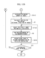
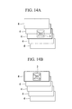
- the galvano-zoom magnification of the galvanometer mirrors 26A and 26B is set for macro observation, and, as shown in Fig. 14A , the three-dimensional macro image 4 is acquired by stacking the two-dimensional images of the X-axis/Y-axis directions of the biological specimen 1 (Step S1-h2). Then, after performing Step S2 to Step S5, the controller 13 calculates the amounts of movement from the position of the center of gravity of the target biological specimen 1 in the X-axis, Y-axis, and Z-axis directions, respectively (Step S6-h2).
- the Z-axis position of the biological specimen 1 is determined (Step S7) by calculating control positions of the galvanometer mirrors 26A and 26B relative to the biological specimen 1 and by judging which two-dimensional image among the two-dimensional images stacked in the Z-axis direction, i.e. the three-dimensional macro image 4 shown in Fig. 14B , contains the biological specimen 1. Then, the stage 11 is moved in the Z-axis direction to adjust the relative positions of the objective lens 28 and the biological specimen 1 (Step S7-h2). Thereafter, Steps S8 to S10 are the same as in the first modification.
- the macro image 4 and micro image 3 may be acquired using the CCD 32 by switching the objective lens 28 to an objective lens of different magnification.
- the stage 11 should be moved relative to the individual biological specimens 1, and the micro images 3 should be individually acquired with the CCD 32.
- magnification information of the objective lens 28 that acquires the micro image 3 may be used when extracting identification information of the biological specimen 1 contained in the macro image 4.
- the identification information of the biological specimen in the macro image 4 and the identification information of the biological specimen 1 in the micro image 3 can be easily matched, and the biological specimen 1 for micro observation can be readily specified.
- Step S6 the low-magnification objective lens 28 for macro observation is switched to the high-magnification objective lens 28 for micro observation (Step S7-h3).
- the stage 11 is moved to a position such that the biological specimen 1 is contained in the viewing range of the high-magnification objective lens 28 (Step S8-h3), and, as shown in Fig. 16 , the micro image 3 of the biological specimen 1 is acquired with the CCD 32.
- Step S8-h3 and Step S9 are performed in this way for each biological specimen 1 for which micro observation is to be performed.
- Step S11 When the next micro observation is to be performed subsequently, the stage 11 is returned to the initial position for the macro-image acquisition (Step S11), the high-magnification objective lens 28 is switched to the low-magnification objective lens 28 for macro observation (Step S12 ), and the process returns to Step S1 ("YES" in Step S10).
- the high-definition micro image 3 can be acquired while tracking the biological specimen 1 with the high-magnification objective lens 28.
- the micro image 3 may be acquired by moving the stage 11 to a position such that these biological specimens 1 are simultaneously kept within the viewing range of the high-magnification objective lens 28.
- pan control of the galvanometer mirrors 26A and 26B may be used together therewith.
- the stage 11 is moved to a position where a plurality of target biological specimens 1 are kept within the viewing range that can be supplemented by the galvano-zoom function of the high-magnification objective lens 28, and each micro image 3 of the individual biological specimens 1 should be acquired by pan control of the galvanometer mirrors 26A and 26B.
- observation may also be similarly performed by switching between the objective lenses 28 each having different magnifications.
Landscapes
- Physics & Mathematics (AREA)
- Chemical & Material Sciences (AREA)
- Analytical Chemistry (AREA)
- General Physics & Mathematics (AREA)
- Optics & Photonics (AREA)
- Engineering & Computer Science (AREA)
- Computer Vision & Pattern Recognition (AREA)
- Multimedia (AREA)
- General Engineering & Computer Science (AREA)
- Microscoopes, Condenser (AREA)
- Investigating, Analyzing Materials By Fluorescence Or Luminescence (AREA)
Abstract
Description
- The present invention relates to a biological observation apparatus.
- Conventionally, observation of various biological specimens has been performed using microscopes and the like, and microscope apparatuses with which image information is acquired by capturing an image of a biological specimen with a camera, etc., and movement and changes over time of the biological specimen are automatically tracked on the basis of the acquired image information have been known (for example, see Japanese Unexamined Patent Application, Publication No.
2008-281720 2008-281720 - However, with the microscope apparatus disclosed in Japanese Unexamined Patent Application, Publication No.
2008-281720 - The present invention provides a biological observation apparatus that is capable of performing detailed fluorescence observation without losing a biological specimen from the viewing range.
- A first aspect of the present invention is a biological observation apparatus that includes a macro-image acquisition unit that acquires a macro image of an observation region that includes a biological specimen; a micro-image acquisition unit that acquires a micro image of the biological specimen; an identification-information storing unit that stores identification information of the biological specimen; a biological-specimen specifying unit that extracts identification information of the biological specimen included in the macro image by performing image processing on the macro image acquired by the macro-image acquisition unit and that specifies the biological specimen for which the extracted identification information corresponds to the identification information stored in the identification-information storing unit; and an adjuster that adjusts relative positions of the biological specimen and a viewing range of the micro image such that the biological specimen specified by the biological-specimen specifying unit is included in the viewing range of the micro image.
- With this aspect, by acquiring a macro image, in which the size of one pixel is large, with the macro-image acquisition unit and by acquiring a micro image, in which the size of one pixel is small as compared with the macro image, with the micro-image acquisition unit, in the macro image, a large-area observation region can be displayed with a larger field of view than the micro image, whereas, in the micro image, a biological specimen can be displayed at higher resolution than the macro image. Therefore, for the biological specimen specified by the biological-specimen specifying unit on the basis of the identification information stored in the identification-information storing unit, the biological specimen can be kept within the viewing range of the macro image even when the biological specimen has moved.
- That is, to perform long-term micro observation of a biological specimen originally intended for observation (for example, to observe a single cell, the required field of view is several tens of micrometers in length and several tens of micrometers in width) by also using the acquisition of the macro image of the observation region in coping with the movement of the biological specimen, it is possible to perform detailed micro observation without losing the biological specimen. As the identification information of the biological specimen, any information that allows the biological specimen to be identified through image processing may be used, examples of which include the position of the center of gravity, shape, size, brightness, etc. of the biological specimen.
- With the above-described first aspect, a stage on which the biological specimen is mounted, a scanner that scans irradiation light emitted from a light source, and a controller that controls a swing-angle range of the scanner may be provided, and the macro-image acquisition unit may acquire the macro image by detecting observation light from the scanning range of the irradiation light scanned in the observation region by the scanner; the micro-image acquisition unit may acquire the micro image by detecting observation light from the scanning range of irradiation light scanned in the observation region by the scanner; and the controller may control the swing-angle range of the scanner such that the scanning amplitude of the irradiation light becomes smaller when acquiring the micro image than when acquiring the macro image.
- With such a configuration, the observation light from the observation region, over which irradiation light is scanned by the scanner, is acquired by the macro-image acquisition unit to obtain a macro image of the observation region, and, additionally, the observation light from the biological specimen, over which irradiation light is scanned by the scanner, is detected by the micro-image acquisition unit to obtain a micro image of the biological specimen.
- In this case, with the number of pixels maintained equal to each other between the macro image and the micro image, the scanning amplitude of the irradiation light is increased when acquiring the macro image; in addition, the scanning amplitude of the irradiation light is decreased when acquiring the micro image, and thus, in the macro image, an observation region can be displayed with a field of view of a larger area than the micro image, whereas, in the micro image, a biological specimen can be displayed at higher resolution than the macro image.
- With the above-described first aspect, the adjuster may adjust the swing-range position of the scanner such that the biological specimen specified by the biological-specimen specifying unit is included in the viewing range of the micro image.
- With such a configuration, the micro image can be easily tracked in accordance with the movement of the biological specimen.
- With the above-described first aspect, an objective lens that radiates the irradiation light scanned by the scanner onto the biological specimen may be provided, and the adjuster may adjust relative positions of the objective lens and the stage in a direction that intersects the optical axis such that the biological specimen specified by the biological-specimen specifying unit is included in the viewing range of the micro image.
- With such a configuration, the micro image can be tracked in accordance with the movement of the biological specimen over a larger area.
- With the above-described first aspect, the macro-image acquisition unit may acquire a three-dimensional macro image of the biological specimen.
- With such a configuration, with the three-dimensional macro image, the micro image can be tracked even for three-dimensional movement, etc. of the biological specimen.
- With the above-described first aspect, a stage on which the biological specimen is mounted, a scanner that scans irradiation light emitted from a light source, and a controller that controls a swing-angle range of the scanner may be provided, and the macro-image acquisition unit may acquire the macro image by capturing observation light from an area in the observation region irradiated by the irradiation light emitted from the light source; the micro-image acquisition unit may acquire the micro image by detecting observation light from the scanning range of the irradiation light scanned in the observation region by the scanner; and the controller may control the swing-angle range of the scanner such that the viewing range for the micro image becomes smaller than the viewing range for the macro image.
- With such a configuration, the scanning amplitude of the irradiation light is decreased with respect to the field of view of the macro image when acquiring the micro image, and thereby, in the macro image, an observation region can be displayed with a field of view of a larger area than the micro image, whereas, in the micro image, a biological specimen can be displayed at higher resolution than the macro image.
- With the above-described first aspect, the adjuster may adjust the swing-range position of the scanner such that the biological specimen specified by the biological-specimen specifying unit is included in the viewing range of the micro image.
- With the above-described first aspect, an objective lens that radiates the irradiation light scanned by the scanner onto the biological specimen may be provided, and the adjuster may adjust relative positions of the objective lens and the stage in the direction that intersects the optical axis such that the biological specimen specified by the biological-specimen specifying unit is included in the viewing range of the micro image.
- With the above-described first aspect, a stage on which the biological specimen is mounted, a plurality of objective lenses of different magnifications that collect observation light from the biological specimen and an observation region that includes the biological specimen, and a revolver that holds the objective lenses and that disposes the objective lenses in an optical path of irradiation light in an exchangeable manner may be provided, and the macro-image acquisition unit may acquire a macro image of the observation region by capturing observation light coming from the observation region and collected by the objective lens having a low magnification; the micro-image acquisition unit may acquire a micro image of the biological specimen by capturing observation light coming from the biological specimen and collected by the objective lens having a high magnification; and the adjuster may adjust relative positions of the objective lenses and the stage in a direction that intersects the optical axis such that the biological specimen specified by the biological-specimen specifying unit is included in the viewing range of the micro image.
- With such a configuration, irradiation light emitted from the light source is irradiated from the low-magnification objective lens onto the observation region, and the observation light therefrom is captured by the image acquisition unit, thereby acquiring the macro image of the observation region. On the other hand, the irradiation light emitted from the light source is radiated from the high-magnification objective lens onto the biological specimen that exists in the observation region, and the micro image of the biological specimen is acquired by capturing the observation light therefrom with the image acquisition unit.
- In this case, the macro image acquired by using the low-magnification objective lens can display a large-area observation region with a larger field of view than the micro image. On the other hand, the micro image acquired by using the high-magnification objective lens can display the biological specimen at a higher resolution than the macro image.
- In addition, by adjusting the relative position with respect to the stage in the direction intersecting the optical axis using the controller, the micro image can be tracked in accordance with the movement of the biological specimen. Therefore, for the biological specimen specified by the biological-specimen specifying unit, the biological specimen can be kept within the viewing range of the macro image even when the biological specimen has moved, and highly detailed micro observation can be performed for an extended period of time without losing the biological specimen.
- With the above-described first aspect, the biological-specimen specifying unit may extract identification information of the biological specimen included in the macro image by using magnification information of the objective lens that acquires the micro image.
- With such a configuration, the identification information of the biological specimen in the macro image and the identification information of the biological specimen in the micro image can be easily matched, and the biological specimen for micro observation can be readily specified.
- With the above-described first aspect, the adjuster may adjust relative positions of the objective lens and the stage in a direction that intersects the optical axis such that the biological specimen specified by the biological specimen specifying unit is included in the viewing range of the micro image.
- With the above-described first aspect, the macro-image acquisition unit may acquire a plurality of the macro images for which the observation regions are adjacent to each other and assemble the adjacent macro images.
- With such a configuration, with the assembled large-area macro image, the biological specimen, which has a large movement range, can be tracked without losing it to perform micro observation.
- With the above-described first aspect, the macro-image acquisition unit may acquire a macro image of the observation region on the basis of transmitted light or returning light from the observation region caused by irradiation of illumination light emitted from a light source, and the micro-image acquisition unit may acquire a micro image of the biological specimen on the basis of fluorescence excited by illumination light emitted from a light source.
- With the above-described first aspect, when identification information of the biological specimen extracted from the macro image changes, the biological-specimen specifying unit may rewrite the identification information of the biological specimen stored in the identification-information storing unit.
- With such a configuration, even when the identification information of the biological specimen changes during observation, observation can be performed by tracking the micro image without losing the biological specimen after the identification information has changed.
- With the above-described first aspect, when the biological specimen undergoes cell division, the biological-specimen specifying unit may store identification information of the biological specimens newly formed by the cell division in the identification-information storing unit and assign mutually-linked identifiers to each of the new biological specimens formed by cell division from the same biological specimen.
- With such a configuration, even when the biological specimen undergoes cell division during observation, the newly formed biological specimens are re-specified, and thus, observation can be performed while tracking the micro images for each of the biological specimens after the cell division. In addition, by assigning mutually-linked identifiers to the new biological specimens formed from the same biological specimen through cell division, the new biological specimens can be observed while associated with each other.
- A second aspect of the present invention is a biological observation apparatus that includes a macro-image light source that radiates illumination light onto an observation region that includes a biological specimen; a macro-image acquisition unit that acquires a macro image of the observation region by capturing transmitted light or returning light from the observation region caused by radiation of the illumination light emitted from the macro-image light source; a micro-image light source that radiates excitation light onto the biological specimen; a micro-image acquisition unit that acquires a micro image of the biological specimen by detecting fluorescence generated at a position in the biological specimen irradiated by the excitation light emitted from the micro-image light source; an identification-information storing unit that stores identification information of the biological specimen; a biological-specimen specifying unit that extracts identification information of the biological specimen included in the macro image by performing image processing on the macro image and that specifies a biological specimen for which the extracted identification information corresponds to the identification information stored in the identification-information storing unit; and moving means that moves the capturing range of the micro-image acquisition unit such that the biological specimen specified by the biological-specimen specifying unit is included in a viewing range of the micro image.
- With this aspect, when the illumination light emitted from the macro-image light source is radiated onto the observation region, the transmitted light or returning light from the observation region is captured by the macro-image acquisition unit, and thereby, the macro image of the observation region is acquired. In addition, when the excitation light emitted from the micro-image light source is radiated onto the biological specimen that exists in the observation region, fluorescence generated at the biological specimen is detected by the micro-image acquisition unit, and thereby, the micro image of the biological specimen in acquired. The returning light is assumed to include reflection light reflected at a surface of the biological specimen and fluorescence generated at the biological specimen.
- The macro image has a larger field of view than the micro image and displays a large-area observation region.
- Therefore, even when the biological specimen has moved, it can be kept within the viewing range of the macro image. On the other hand, the micro image is captured at higher resolution than the macro image. Therefore, as compared with the case of displaying the biological specimen with the macro image, the biological specimen can be displayed in more detail in the micro image.
- In the biological observation apparatus according to this aspect, the biological-specimen specifying unit specifies the biological specimen for which the identification information extracted by performing image processing on the macro image corresponds to the identification information stored in the identification-information storing unit, the moving means moves the capturing range of the micro-image acquisition unit such that the specified biological specimen is included in the viewing range of the micro image, and thereby, the micro image can be tracked in accordance with the movement of the biological specimen.
- Accordingly, to perform micro observation of a biological specimen originally intended for observation for an extended period of time, it is possible to cope with the movement of the biological specimen by using the acquisition of the macro image of the observation region together therewith, and it is possible to perform detailed micro observation without losing the biological specimen from the field of view of the micro image when the biological specimen moves, etc.
- In addition, if identification information for a plurality of biological specimens is stored in the identification-information storing unit, each of the plurality of the biological specimens can be specified. In addition, by moving the capturing range of the micro-image acquisition unit for each biological specimen with the moving means, fluorescence observation can be performed by acquiring micro images for each of the plurality of the desired biological specimens.
- With the above-described second aspect, the micro-image acquisition unit may include a scanner that scans the excitation light emitted from the micro-image light source, a detector that detects the fluorescence generated at the biological specimen, and an image-constructing unit that constructs the micro image on the basis of the fluorescence detected by the detector; and the moving means may adjust a swing-angle range of the scanner.
- With such a configuration, the detector detects the fluorescence generated by scanning the excitation light over the biological specimen with the scanner, and the micro image of the biological specimen is constructed by the image-constructing unit on the basis of the detected signal. Then, the swing-angle range of the scanner is adjusted by the moving means, and the scanning range of the excitation light is changed in accordance with the movement of the biological specimen, thereby allowing the micro image to be easily tracked in accordance with the movement of the biological specimen.
- With the above-described second aspect, an objective lens that irradiates the biological specimen with the excitation light emitted from the micro-image light source and that also collects the fluorescence generated at a position irradiated by the excitation light, and a stage on which the biological specimen is mounted and that is movable in a direction that intersects an optical axis of the objective lens may be provided, and the moving means may relatively move the objective lens and the stage in the direction that intersects the optical axis.
- By relatively moving the objective lens and the stage in the direction that intersects the optical axis with the moving means, the micro image can be tracked over a larger area in comparison with the scanning range of the scanner. Therefore, even when the biological specimen attempts to move out of the viewing range, it becomes possible to keep the biological specimen within the viewing range.
- With the above-described second aspect, when identification information of the biological specimen extracted from the macro image changes, the biological-specimen specifying unit may rewrite the identification information of the biological specimen stored in the identification-information storing unit.
- With the above-described second aspect, when the biological specimen undergoes cell division, the biological-specimen specifying unit may store identification information of the biological specimens newly formed by the cell division in the identification-information storing unit and assigns mutually-linked identifiers to each of the new biological specimens formed by cell division from the same biological specimen.
- With the above-described second aspect, objective lenses, which have different magnifications may be provided in an exchangeable manner, and the biological-specimen specifying unit may extract identification information of the biological specimen by using magnification information of the objective lenses.
- With such a configuration, identification information of the biological specimens can be easily matched between images acquired with the objective lenses of different magnification by converting the magnification information of the objective lenses. Therefore, even when separate images of the biological specimen are to be acquired in multiple stages, by changing the magnification of the objective lenses, it is possible to readily specify the biological specimen for each image.
- According to the present invention, an advantage is afforded in that detailed fluorescence observation can be performed without losing a biological specimen from the viewing range.
-
-
Fig. 1 is a diagram showing, in outline, the configuration of a biological observation apparatus according to an embodiment of the present invention. -
Fig. 2 is a diagram showing an example of the viewing range for each galvano zoom of an LSM inFig. 1 . -
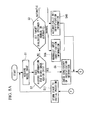
Fig. 3A is a flowchart showing a biological-specimen observation procedure performed by the biological observation apparatus ofFig. 1 . -
Fig. 3B is a flowchart showing a biological-specimen observation procedure performed by the biological observation apparatus ofFig. 1 . -
Fig. 4A is a diagram showing a macro image acquired in a previous round. -
Fig. 4B is a diagram showing a macro image acquired in a current round. -
Fig. 4C is a diagram showing an acquisition range of a micro image, which has changed in accordance with the movement of a biological specimen. -
Fig. 5A is a diagram showing acquisition ranges of a macro image and a micro image before movement of the biological specimen. -
Fig. 5B is a diagram showing acquisition ranges of a macro image and a micro image after movement of the biological specimen. -
Fig. 6A is a diagram showing acquisition ranges of a macro image and a micro image before cell division of a biological specimen. -
Fig. 6B is a diagram showing acquisition ranges of a macro image and a micro image after cell division of the biological specimen. -
Fig. 7A is a flowchart showing an observation procedure for the biological observation apparatus ofFig. 1 , in a case in which a biological specimen has undergone cell division. -
Fig. 7B is a flowchart showing an observation procedure for the biological observation apparatus ofFig. 1 , in a case in which a biological specimen has undergone cell division. -
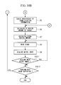
Fig. 8A is a flowchart showing a procedure for performing observation with the biological observation apparatus ofFig. 1 while controlling a stage. -
Fig. 8B is a flowchart showing a procedure for performing observation with the biological observation apparatus ofFig. 1 while controlling a stage. -
Fig. 9A is a diagram showing an assembled macro image. -
Fig. 9B is a diagram showing an assembled macro image from a current round. -
Fig. 9C is a diagram showing a micro-image acquisition range which is changed in accordance with the movement of a biological specimen.
Fig. 10A is a flowchart showing a procedure for performing observation with the biological observation apparatus ofFig. 1 by assembling macro images of adjacent observation regions.
Fig. 10B is a flowchart showing a procedure for performing observation with the biological observation apparatus ofFig. 1 by assembling macro images of adjacent observation regions.
Fig. 11 is a diagram showing a case in which a biological specimen has moved into a space between macro images.
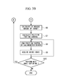
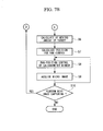
Fig. 12A is a flowchart showing an observation procedure for a biological observation apparatus according to a first modification of an embodiment of the present invention.
Fig. 12B is a flowchart showing an observation procedure for a biological observation apparatus according to a first modification of an embodiment of the present invention.
Fig. 13A is a flowchart showing an observation procedure for a biological observation apparatus according to a second modification of an embodiment of the present invention.
Fig. 13B is a flowchart showing an observation procedure for a biological observation apparatus according to a second modification of an embodiment of the present invention.
Fig. 14A is a diagram showing a three-dimensional macro image.
Fig. 14B is a diagram showing, in the three-dimensional macro image ofFig. 14A , a two-dimensional macro image in which a biological specimen exists.
Fig. 15A is a flowchart showing an observation procedure for a biological observation apparatus according to a third modification of an embodiment of the present invention. -
Fig. 15B is a flowchart showing an observation procedure for a biological observation apparatus according to a third modification of an embodiment of the present invention. -
Fig. 16 is a diagram showing the field of view of a high-magnification objective lens for a macro image. - A biological observation apparatus according to an embodiment of the present invention will be described below, with reference to the drawings.
- As shown in
Fig. 1 , abiological observation apparatus 100 according to this embodiment is for performing detailed observation of abiological specimen 1, such as a cell, a microorganism, and the like. Thebiological observation apparatus 100 is provided with astage 11 on which thebiological specimen 1 is mounted; anoptical system 20 that radiates irradiation light toward thebiological specimen 1 on thestage 11 and that detects light (observation light) from thebiological specimen 1 irradiated with the illumination light and a surrounding region (hereinafter referred to as "observation region") 2 that includes thebiological specimen 1; a controller (control unit) 13 that controls the position of thestage 11 and the position irradiated by the irradiation light and that constructs images on the basis of fluorescence detected by theoptical system 20; and amonitor 12 that displays images, etc. constructed by thecontroller 13. - The
stage 11 is provided with a moving mechanism (not shown) and is arranged to be movable in a direction that intersects an optical axis of the irradiation light that is radiated onto thebiological specimen 1 and theobservation region 2 from theoptical system 20. Thestage 11 is configured such that one or a plurality of thebiological specimens 1 are disposed in theobservation region 2. - The
optical system 20 is provided with a macro-imagelight source 22 that radiates illumination light, serving as the irradiation light, toward theobservation region 2; a micro-imagelight source 24, such as a laser light source, etc., that radiates excitation light toward thebiological specimen 1; galvanometer mirrors (scanners) 26A and 26B that scan the excitation light emitted from the micro-imagelight source 24 over thebiological specimen 1; anobjective lens 28 that collects light (transmitted light) that has passed through theobservation region 2, among the illumination light radiated from the macro-imagelight source 22, and fluorescence generated at a position in thebiological specimen 1 irradiated by the excitation light radiated from the micro-imagelight source 24 via the galvanometer mirrors 26A and 26B; a two-dimensional image acquisition device (a macro-image acquisition unit, hereinafter described with a "CCD" as an example) 32, such as a CCD, that acquires amacro image 4 of theobservation region 2 by capturing the transmitted light collected by theobjective lens 28; and a PMT (photomultiplier tube) 34 that detects fluorescence collected by theobjective lens 28. - This
optical system 20 is provided with amirror 36 that transmits the transmitted light collected by theobjective lens 28 and that reflects fluorescence; anoptical filter 38 that eliminates an unnecessary wavelength band from the transmitted light that is incident on theCCD 32 upon passing through themirror 36; an excitation DM (dichroic mirror) 42 that transmits the excitation light emitted from the micro-imagelight source 24 and that reflects fluorescence returning from thebiological specimen 1; and apin hole 44 where the fluorescence, which enters thePMT 34 reflected by theexcitation DM 42, passes through. - So long as emitted illumination light includes wavelengths that pass through the
observation region 2, any light source may be employed as the macro-imagelight source 22, including, for example, a halogen lamp, a light-emitting diode, a laser, or the like. Instead of a laser light source, for example, a xenon lamp, a mercury lamp, and the like may be employed As the micro-imagelight source 24, so long as the emitted excitation light has a wavelength that excites fluorescent materials, etc. contained in thebiological specimen 1. - The
CCD 32 is configured to have a large viewing range so as to capture themacro image 4 in which theobservation region 2, having a large area, is captured. Because the large-area observation region 2 appears in themacro image 4, the movingbiological specimen 1 can be kept within the viewing range. In addition, a region of the micro image 3(micro image region) that is for capturing an image of thebiological specimen 1 to be observed is displayed in themacro image 4. A highly sensitive EMCCD (electron Multiplying CCD) may be employed as theCCD 32. - The galvanometer mirrors 26A and 26B are an
X-galvanometer mirror 26A and a Y-galvanometer mirror 26B that scan the excitation light emitted from the micro-imagelight source 24 and passing through theexcitation DM 42 in the x-axis direction or the y-axis direction on thebiological specimen 1 on thestage 11, and that are respectively disposed in the optical path of the excitation light in a manner that allows changing of a swing-angle range (swing-range position and scanning-amplitude for the excitation light). - The
PMT 34 is configured so as to detect fluorescence generated at thebiological specimen 1 irradiated with the illumination light and to output the detected signal (fluorescence brightness) for each pixel to thecontroller 13. - The galvanometer mirrors 26A and 26B and the
PMT 34, together with thecontroller 13, constitute amicro-image acquisition unit 35 that acquires themicro image 3 of thebiological specimen 1. It is preferable that themicro-image acquisition unit 35 be a laser-scanning microscope (LSM). - With this
micro-image acquisition unit 35, thePMT 34 detects the detected signal in synchronization with the timing of scanning of the excitation light by the galvanometer mirrors 26A and 26B, and thecontroller 13 constructs a two-dimensional image on the basis of the detected signal input from thePMT 34 for each pixel, thereby acquiring themicro image 3 of thebiological specimen 1. - The
micro-image acquisition unit 35 constituted in this way is configured to be able to adjust the field of view and pixel resolution by means of a galvano-zoom function, more specifically, by changing the scanning amplitude (maximum angle of scanning) of the galvanometer mirrors 26A and 26B while keeping the number of pixels constant. - For example, as shown in
Fig. 2 , the resolution increases and the viewing range decreases in the order zoom Z1, zoom Z2, and zoom Z3, and an image having an image-acquisition range and resolution substantially equivalent to themacro image 4 of theobservation region 2 taken with theCCD 32 is acquired withzoom 1. In addition, themicro image 3 in which thebiological specimen 1 is displayed in detail with a smaller image-acquisition range and at a higher resolution than themacro image 4 of theobservation region 2 taken with theCCD 32 is acquired with zoom Z2 or zoom Z3. - The
objective lens 28 irradiates thebiological specimen 1 with the excitation light that has been scanned by the galvanometer mirrors 26A and 26B reflected at themirror 36, and, on the other hand, collects fluorescence generated at thebiological specimen 1 due to irradiation with the excitation light and transmitted light that has passed through theobservation region 2 due to irradiation with the illumination light. In addition, theobjective lens 28 is provided in arevolver 29 together with a plurality of otherobjective lenses 28 having different magnifications, which are disposed therein in an exchangeable manner. - The
controller 13 is provided with an identification-information storing unit 15 that stores identification information for identifying thebiological specimen 1, a biological-specimen specifying unit 17 that specifies thebiological specimen 1 for acquisition of themicro image 3, and a pan controller (adjuster, moving means) 19 for adjusting the swing-angle range (swing-range position) of the galvanometer mirrors 26A and 26B (hereinafter referred to as "pan control"). - The
controller 13 serves as an image-constructing unit that constructs themicro image 3 described above and also performs storing processing for the identification-information storing unit 15, specifying processing for the biological-specimen specifying unit 17, and pan control for thepan controller 19. - As the identification information to be stored in the identification-
information storing unit 15, any information may be used so long as it allows identification of thebiological specimen 1 by performing image processing on themacro image 4 of theobservation region 2 acquired by theCCD 32, examples of which include the position of the center of gravity, shape, size, brightness, etc. of thebiological specimen 1. - The biological-
specimen specifying unit 17 reads out themacro image 4 acquired by theCCD 32 and applies image processing thereto, thereby extracting the identification information of thebiological specimen 1 included in themacro image 4. In addition, the biological-specimen specifying unit 17 is configured so as to specify as a target thebiological specimen 1, for which the extracted identification information corresponds to the identification information stored in the identification-information storing unit 15. - The
pan controller 19 scans the excitation light radiated onto thebiological specimen 1 by performing pan control of theX-galvanometer mirror 26A and the Y-galvanometer mirror 26B such that thebiological specimen 1 specified by the biological-specimen specifying unit 17 is included in the viewing range of themicro image 3. By doing so, thepan controller 19 moves the capturing range of themicro-image acquisition unit 35 in this manner. Note that, thecontroller 13 may control the movement of thestage 11 in the direction that intersects the optical axis of theobjective lens 28. - The operation of the thus-configured
biological observation apparatus 100 according to this embodiment will be described with reference to the flowchart ofFig. 3A and3B . - When observing, for example, cultured cells, using the
biological observation apparatus 100 according to this embodiment, a petri dish (not shown) in which a plurality of cells (biological specimens) are cultured is mounted on thestage 11, and the illumination light is radiated from the macro-imagelight source 22 toward theobservation region 2 that includes thebiological specimens 1 to be observed. - Then, the transmitted light that has passed through the
observation region 2 is collected by theobjective lens 28 and is incident on theCCD 32 upon passing through themirror 36 and theoptical filter 38. Accordingly, the transmitted light is captured in theCCD 32, and thus, themacro image 4 of theobservation region 2 is acquired and is displayed on the monitor 12 (Step S1). - In the
controller 13, it is judged whether history information of a micro-image region exists in themacro image 4, that is to say, whether the identification information for thebiological specimen 1 to be observed is stored in the identification-information storing unit 15 (Step S2). If history information of the micro-image region does not exist ("NO" in Step S2), it is selected whether to manually set or automatically set thebiological specimen 1 to be observed as a target (Step S3). - When the target is to be manually set ("manual" in Step S3), the desired
biological specimens 1 that exist in themacro image 4 on themonitor 12 are individually selected by an observer. Accordingly, the identification information (position of center of gravity, shape, size, brightness, etc.) of the selectedbiological specimens 1 is input to the identification-information storing unit 15 and is stored therein as parameters (Step S4A). - On the other hand, when the
biological specimens 1 to be observed are to be automatically set ("automatic" in Step S3), regions in a predetermined brightness value or greater, are identified by the identification-information storing unit 15 as thebiological specimens 1 to be observed, and the identification information thereof is stored as parameters (Step S4B). - In this way, the manually-set
biological specimens 1 or the automatically-setbiological specimens 1 are specified in thecontroller 13 as targets for micro observation with themicro image 3. - In Step S2, in the case in which the
macro image 4 as shown inFig. 4A has been acquired in the past (previous round), and history information for the micro-image region thereof exists ("YES" in Step S2), the biological-specimen specifying unit 17 applies image processing to themacro image 4, as shown inFig. 4B , that has been acquired in the current round, thereby extracting identification information for respectivebiological specimens macro image 4 of the current round. - Then, consistency is checked between the extracted identification information and the identification information in the
macro image 4 acquired in the previous round, which is stored in the identification-information storing unit 15, and thebiological specimens - Next, the
controller 13 calculates the amount of movement in the X-axis direction and the Y-axis direction, respectively, from the positions of the centers of gravity, etc. of the targetbiological specimens biological specimens biological specimens biological specimens controller 13 calculates pan positions of the galvanometer mirrors 26A and 26B for the respectivebiological specimens - Next, in the case where micro observation of the
biological specimen 1A is performed, on the basis of the pan positions of the galvanometer mirrors 26A and 26B calculated in Step S7, thepan controller 19 adjusts the pan positions (swing-angle ranges) of theX-galvanometer mirror 26A and the Y-galvanometer mirror 26B such that thebiological specimen 1A is included in the viewing range of themicro image 3A (Step S8). In addition, depending on the magnification required for the micro observation, the galvano-zoom magnification can also be set. - In this state, the excitation light emitted from the micro-image
light source 24 passes through theexcitation DM 42, is reflected at theX-galvanometer mirror 26A and the Y-galvanometer mirror 26B, and is radiated onto thebiological specimen 1A by theobjective lens 28, via themirror 36. - When fluorescence is generated at the position in the
biological specimen 1A irradiated by the excitation light scanned by theX-galvanometer mirror 26A and the Y-galvanometer mirror 26B, the fluorescence is collected by theobjective lens 28 and is reflected at themirror 36, the Y-galvanometer mirror 26B, and theX-galvanometer mirror 26A. Then, the fluorescence is reflected at theexcitation DM 42, is detected by thePMT 34 upon passing through thepin hole 44, and is input to thecontroller 13 as the detected signal. - A two-dimensional image is constructed in the
controller 13 on the basis of the detected signals for individual pixels input from thePMT 34. Accordingly, themicro image 3A of thebiological specimen 1A is acquired and is displayed on the monitor 12 (Step S9). - Next, in the case where micro observation of the
biological specimen 1B is performed, thepan controller 19 adjusts the pan positions of the galvanometer mirrors 26A and 26B such that thebiological specimen 1B is contained in the viewing range of themicro image 3B (Step S8). Then, thebiological specimen 1B is irradiated with the excitation light, the generated fluorescence is detected by thePMT 34, and a two-dimensional image is constructed by thecontroller 13. Accordingly, themicro image 3B of thebiological specimen 1B is acquired and is displayed on the monitor 12 (Step S9). Step S8 and Step S9 are repeated in this way for a plurality of thebiological specimens - In this case, by scanning the excitation light in accordance with the swing-angle ranges of the X-galvanometer mirror and the Y-galvanometer mirror for which pan control is performed by the
pan controller 19 so as to contain the specifiedbiological specimens micro images Fig. 4C , it is possible to track the respectivemicro images biological specimens - For example, when the respective
biological specimens micro images macro image 4 move as shown inFig. 5A , it is possible to track the respectivemicro images biological specimens Fig. 5B . - The
CCD 32 can perform observation using themacro image 4 at a faster rate in comparison with themicro-image acquisition unit 35 and, even in the case in which the movement speed of thebiological specimens micro images biological specimens macro image 4 of theobservation region 2. - Once
micro images biological specimens micro-image acquisition unit 35, the process returns to Step S1 if next micro observation is to be subsequently performed, and the operation from Step S1 to Step S9 is repeated until observation is completed (Step S10). - As described above, with the
biological observation apparatus 100 according to this embodiment, themacro image 4 is initially acquired; the targetbiological specimens specimen specifying unit 17 by performing image processing on themacro image 4 of theobservation region 2; and the excitation light is scanned by performing pan control of the galvanometer mirrors 26A and 26B with thepan controller 19 such that the specifiedbiological specimens micro images micro images biological specimens - That is, by also making use of macro observation of the
biological specimen 1 in coping with the movement of thebiological specimens 1, etc., it becomes possible to perform detailed micro observation for an extended period of time without losing thebiological specimens - Although the case of observing two
biological specimens biological specimen 1 may be observed or three or morebiological specimens 1 may be observed. In addition, in this embodiment, the PMT may be disposed on a transmission side of thebiological specimen 1, and the transmitted light from thebiological specimen 1 may be detected by this PMT. - In this embodiment, when, for example, the identification information of the
biological specimen 1 extracted from themacro image 4 changes, the biological-specimen specifying unit 17 may rewrite the identification information of thebiological specimen 1 stored in the identification-information storing unit 15 with the updated position of the center of gravity, shape, size, brightness, etc. By doing so, even when the identification information for the targetbiological specimen 1 changes during observation, observation of themicro image 3 can be performed without losing thebiological specimen 1 whose identification information has changed. - In this embodiment, when, for example, the
biological specimen 1 undergoes cell division, the biological-specimen specifying unit 17 may store identification information of the newbiological specimens 1 formed by the cell division in the identification-information storing unit 15 and may assign mutually-linked identifiers to the respective newbiological specimens 1 formed from the samebiological specimen 1 by cell division. - For example, as shown in the flowcharts of
Fig. 6A, 6B , and7 , the consistency of the identification information of thebiological specimen 1 is checked in Step S5-1, and once two sets of identification information for biological specimens 1-1 and 1-2 are extracted from themacro image 4, the biological-specimen specifying unit 17 determines that thebiological specimen 1 has divided into the two biological specimens 1-1 and 1-2 ("YES" in Step 5-2). - Then the identification information of the new biological specimens 1-1 and 1-2 formed by cell division is stored in the identification-
information storing unit 15, and micro image regions of the biological specimens 1-1 and 1-2 are added thereto (Step S5-3). In addition, mutually-linked identifiers are assigned to the new biological specimens 1-1 and 1-2, respectively. Next, thecontroller 13 repeats Step S6 to Step S9 for each of the biological specimens 1-1 and 1-2 to acquire themicro images - By doing so, even when the
biological specimen 1 undergoes cell division during observation, the newly formed biological specimen 1-2 is additionally specified, and the new biological specimens 1-1 and 1-2 can be tracked with themicro images biological specimen 1 may be re-specified by the biological-specimen specifying unit 17, not only when cell division occurs, but also when thebiological specimens 1 combine, disappear, etc. - Although the
biological specimens biological specimens stage 11 with thecontroller 13 in the two-dimensional directions (X-axis direction and Y-axis direction) that intersect the optical axis. - For example, as shown in the flowchart of
Fig. 8A and8B , once the amount of movement in the X-axis/Y-axis directions is calculated for the respectivebiological specimens controller 13 calculates the amounts of stage movement for moving thestage 11 to the respective positions of thebiological specimens biological specimens micro images - In this case, the amount of movement of the
stage 11 to each observation position should be individually calculated with thecontroller 13 by individually specifying the observation positions using themicro images biological specimens - Next, on the basis of the amount of movement of the
stage 11 calculated for each of thebiological specimens stage 11 is moved so that thebiological specimen 1A is contained in the viewing range of themicro image 3A (Step S8'), and themicro image 3A is acquired (Step S9'). Similarly, thestage 11 is moved so that thebiological specimen 1B is contained in the viewing range of themicro image 3B (Step S8'), and themicro image 3B is acquired (Step S9). - When the next micro observation is to be performed subsequently ("YES" in Step 10), the
stage 11 is returned to the initial position for macro observation (Step 11), and the process returns to Step S1. On the other hand, when observation is not to be performed, the process is terminated ("NO" in Step S10). - Although observation is performed with a single
macro image 4 in this embodiment, for example, as shown inFigs. 9A, 9B, and 9C , observation may be performed by assembling a plurality ofmacro images 4 whoseobservation regions 2 are adjacent to each other. For example, as shown in the flowchart ofFig. 10A and10B , to additionally acquire a macro image 4-2 of the observation region 2 ("YES" in Step S1-2), after acquiring a macro image 4-1 of the observation region 2 (Step S1-1) adjacent thereto, thestage 11 is moved to the adjacent observation region 2 (Step S1-3), and the macro image 4-2 is acquired (Step S1-1). - In addition, for example, once four macro images 4-1, 4-2, 4-3, and 4-4 of the four
adjacent observation regions 2 are acquired ("NO" in Step S1-2), as shown inFig. 9A , the acquired macro images 4-1, 4-2, 4-3, and 4-4 are assembled (Step S1-4). - Next, Step S2 to Step S9 are repeated within the range of all macro images 4-1, 4-2, 4-3, and 4-4 assembled as shown in
Fig. 9B . In this case, consistency of the identification information is checked for each of thebiological specimens - In addition, the amount of movement for individual
biological specimens biological specimens biological specimens macro images Fig. 9C . - Once micro observation of the desired
biological specimens stage 11 is returned to the initial position for macro observation (Step S11), and the process returns to Step S1. On the other hand, when observation is not to be performed, the process is terminated ("NO" in Step S10). By doing so, micro observation can be performed while tracking the movement of thebiological specimen 1, etc., over a large area. - With this modification, for example, micro observation may be performed by using pan control of the galvanometer mirrors 26A and 26B together with moving the
stage 11 in the X-axis/Y-axis directions. In this case, for example, thestage 11 should be moved to a position where a plurality of micro-image acquisition ranges are contained in the viewing range for the galvano-zoom magnification of 1.0, and micro-observation positions should be individually adjusted by pan control of the galvanometer mirrors 26A and 26B. - In addition, as shown in
Fig. 11 , when thebiological specimen 1 exists at a position bridging the assembled macro images 4-2 and 4-3, to acquire themicro image 3B of thebiological specimen 1B, thestage 11 may be moved such that the position of the center of gravity of thebiological specimen 1B is located at the center of the macro image 4-2. - This embodiment can be modified as follows.
- For example, in this embodiment, the
macro image 4 of thebiological specimen 1 is acquired using the macro-imagelight source 22 and theCCD 32; however, as a first modification, themacro image 4 may be acquired using the galvano-zoom function of themicro-image acquisition unit 35. - In this case, as shown in the flowchart of
Fig. 12A and12B , in Step S1-h1, for example, the galvano-zoom magnification of the galvanometer mirrors 26A and 26B is set to 1.0 (the maximum field of view of the galvanometer mirrors 26A and 26B) for macro observation(for example, see zoom Z1 shown inFig. 2 ). - Then, the excitation light is emitted from the micro-image
light source 24 to scan over thebiological specimen 1 with the galvanometer mirrors 26A and 26B, and themacro image 4 is acquired with thecontroller 13 by detecting fluorescence generated at thebiological specimen 1 with thePMT 34. Step S2 to Step S8 are the same as in the embodiment described above. - In addition, in Step S9-h1, the
micro image 3 is acquired by setting the galvano-zoom magnification of the galvanometer mirrors 26A and 26B for micro observation (for example, see zoom Z2 or zoom Z3 shown inFig. 2 ). - As described above, according to this modification, by performing macro observation and micro observation with the
micro-image acquisition unit 35, it is possible to track and to observe even thebiological specimen 1 that cannot be determined unless themicro-image acquisition unit 35 is used. In this modification, particularly for macro observation, a PMT may be disposed on the transmission side of thebiological specimen 1, and the transmitted light from thebiological specimen 1 may be detected with this PMT. - As a second modification, in the case in which the
micro-image acquisition unit 35 is a laser-scanning microscope, optical slice images can be acquired. Here, for example, when acquiring themacro image 4 with themicro-image acquisition unit 35 by using the galvano-zoom function, a three-dimensionalmacro image 4 may be acquired by changing the relative positions of theobjective lens 28 and thebiological specimen 1 in the optical axis direction (Z-axis direction) with thecontroller 13. - For example, the three-dimensional image should be acquired by performing two-dimensional scanning on the
biological specimen 1 in the X-axis/Y-axis directions with the galvanometer mirrors 26A and 26B, while moving thestage 11 in the Z-axis direction, and by stacking two-dimensional images of thebiological specimen 1 at each relative position of theobjective lens 28 and thebiological specimen 1. - In this case, as shown in the flowchart of
Fig. 13A and13B , the galvano-zoom magnification of the galvanometer mirrors 26A and 26B is set for macro observation, and, as shown inFig. 14A , the three-dimensionalmacro image 4 is acquired by stacking the two-dimensional images of the X-axis/Y-axis directions of the biological specimen 1 (Step S1-h2). Then, after performing Step S2 to Step S5, thecontroller 13 calculates the amounts of movement from the position of the center of gravity of the targetbiological specimen 1 in the X-axis, Y-axis, and Z-axis directions, respectively (Step S6-h2). - In addition, the Z-axis position of the
biological specimen 1 is determined (Step S7) by calculating control positions of the galvanometer mirrors 26A and 26B relative to thebiological specimen 1 and by judging which two-dimensional image among the two-dimensional images stacked in the Z-axis direction, i.e. the three-dimensionalmacro image 4 shown inFig. 14B , contains thebiological specimen 1. Then, thestage 11 is moved in the Z-axis direction to adjust the relative positions of theobjective lens 28 and the biological specimen 1 (Step S7-h2). Thereafter, Steps S8 to S10 are the same as in the first modification. - As a third modification, for example, the
macro image 4 andmicro image 3 may be acquired using theCCD 32 by switching theobjective lens 28 to an objective lens of different magnification. In addition, when there are a plurality of targets for micro observation, thestage 11 should be moved relative to the individualbiological specimens 1, and themicro images 3 should be individually acquired with theCCD 32. - In addition, magnification information of the
objective lens 28 that acquires themicro image 3 may be used when extracting identification information of thebiological specimen 1 contained in themacro image 4. By doing so, the identification information of the biological specimen in themacro image 4 and the identification information of thebiological specimen 1 in themicro image 3 can be easily matched, and thebiological specimen 1 for micro observation can be readily specified. - For example, as shown in the flowchart of
Fig. 15A and15B , once the amount of movement of thebiological specimen 1 in the X-axis/Y-axis directions is calculated in Step S6, the low-magnification objective lens 28 for macro observation is switched to the high-magnification objective lens 28 for micro observation (Step S7-h3). Then, thestage 11 is moved to a position such that thebiological specimen 1 is contained in the viewing range of the high-magnification objective lens 28 (Step S8-h3), and, as shown inFig. 16 , themicro image 3 of thebiological specimen 1 is acquired with theCCD 32. Step S8-h3 and Step S9 are performed in this way for eachbiological specimen 1 for which micro observation is to be performed. - When the next micro observation is to be performed subsequently, the
stage 11 is returned to the initial position for the macro-image acquisition (Step S11), the high-magnification objective lens 28 is switched to the low-magnification objective lens 28 for macro observation (Step S12 ), and the process returns to Step S1 ("YES" in Step S10). - According to this modification, the high-definition
micro image 3 can be acquired while tracking thebiological specimen 1 with the high-magnification objective lens 28. When two or more targetbiological specimens 1 are included in the viewing range of the high-magnification objective lens 28, themicro image 3 may be acquired by moving thestage 11 to a position such that thesebiological specimens 1 are simultaneously kept within the viewing range of the high-magnification objective lens 28. - In this modification, the case in which the
micro image 3 and the micro image are both acquired by theCCD 32 has been described; however, for example, as shown in the above-described embodiment, even when themacro image 3 is acquired by theCCD 32 and themicro image 4 is acquired by themicro-image acquisition unit 35, observation may also be performed similarly by switching between theobjective lenses 28 each having different magnifications. - In this case, when adjusting the micro-observation position in the viewing range of the
micro image 3, pan control of the galvanometer mirrors 26A and 26B may be used together therewith. For example, thestage 11 is moved to a position where a plurality of targetbiological specimens 1 are kept within the viewing range that can be supplemented by the galvano-zoom function of the high-magnification objective lens 28, and eachmicro image 3 of the individualbiological specimens 1 should be acquired by pan control of the galvanometer mirrors 26A and 26B. - In addition, for example, when the
micro image 3 and themacro image 4 are acquired by themicro-image acquisition unit 35, observation may also be similarly performed by switching between theobjective lenses 28 each having different magnifications. - The embodiments of the present invention have been described above with reference to the drawings; however, the specific configuration is not limited to these embodiments, and design alterations, etc. within a range that does not depart from the gist of the present invention are also encompassed.
Claims (17)
- A biological observation apparatus comprising:a macro-image acquisition unit that acquires a macro image of an observation region that includes a biological specimen;a micro-image acquisition unit that acquires a micro image of the biological specimen;an identification-information storing unit that stores identification information of the biological specimen;a biological-specimen specifying unit that extracts identification information of the biological specimen included in the macro image by performing image processing on the macro image acquired by the macro-image acquisition unit and that specifies the biological specimen for which the extracted identification information corresponds to the identification information stored in the identification-information storing unit; andan adjuster that adjusts relative positions of the biological specimen and a viewing range of the micro image such that the biological specimen specified by the biological-specimen specifying unit is included in the viewing range of the micro image.
- A biological observation apparatus according to Claim 1 further comprising:a stage on which the biological specimen is mounted;a scanner that scans irradiation light emitted from a light source; anda controller that controls a swing-angle range of the scanner; whereinthe macro-image acquisition unit acquires the macro image by detecting observation light from the scanning range of the irradiation light scanned in the observation region by the scanner;the micro-image acquisition unit acquires the micro image by detecting observation light from the scanning range of irradiation light scanned in the observation region by the scanner; andthe controller controls the swing-angle range of the scanner such that the scanning amplitude of the irradiation light becomes smaller when acquiring the micro image than when acquiring the macro image.
- A biological observation apparatus according to Claim 2, wherein the macro-image acquisition unit acquires a three-dimensional macro image of the biological specimen.
- A biological observation apparatus according to Claim 1, further comprising:a stage on which the biological specimen is mounted;a scanner that scans irradiation light emitted from a light source; anda controller that controls a swing-angle range of the scanner; whereinthe macro-image acquisition unit acquires the macro image by capturing observation light from an area in the observation region irradiated with the irradiation light emitted from the light source;the micro-image acquisition unit acquires the micro image by detecting observation light from the scanning range of the irradiation light scanned in the observation region by the scanner; andthe controller controls the swing-angle range of the scanner such that the viewing range for the micro image becomes smaller than the viewing range for the macro image.
- A biological observation apparatus according to Claim 2 or 4, wherein the adjuster adjusts the swing-range position of the scanner such that the biological specimen specified by the biological-specimen specifying unit is included in the viewing range of the micro image.
- A biological observation apparatus according to Claim 2 or 4, further comprising:an objective lens that radiates the irradiation light scanned by the scanner onto the biological specimen,wherein the adjuster adjusts relative positions of the objective lens and the stage in the direction that intersects the optical axis such that the biological specimen specified by the biological-specimen specifying unit is included in the viewing range of the micro image.
- A biological observation apparatus according to Claim 1, further comprising:a stage on which the biological specimen is mounted;a plurality of objective lenses of different magnifications that collect observation light from the biological specimen and an observation region that includes the biological specimen; anda revolver that holds the objective lenses and that disposes the objective lenses in an optical path of irradiation light in an exchangeable manner; whereinthe macro-image acquisition unit acquires a macro image of the observation region by capturing observation light coming from the observation region and collected by the objective lens having a low magnification;the micro-image acquisition unit acquires a micro image of the biological specimen by capturing observation light coming from the biological specimen and collected by the objective lens having a high magnification; andthe adjuster adjusts relative positions of the objective lenses and the stage in a direction that intersects the optical axis such that the biological specimen specified by the biological-specimen specifying unit is included in viewing range of the micro image.
- A biological observation apparatus according to Claim 7, wherein the biological-specimen specifying unit extracts identification information of the biological specimen included in the macro image by using magnification information of the objective lens that acquires the micro image.
- A biological observation apparatus according to Claim 1, wherein the adjuster adjusts relative positions of the objective lens and the stage in a direction that intersects the optical axis such that the biological specimen specified by the biological specimen specifying unit is included in the viewing range of the micro image.
- A biological observation apparatus according to Claim 9, wherein the macro-image acquisition unit acquires a plurality of the macro images for which the observation regions are adjacent to each other, and assembles the adjacent macro images.
- A biological observation apparatus according to one of Claims 1 to 10, wherein
the macro-image acquisition unit acquires a macro image of the observation region on the basis of transmitted light or returning light from the observation region caused by irradiation of illumination light emitted from a light source, and
the micro-image acquisition unit acquires a micro image of the biological specimen on the basis of fluorescence excited by illumination light emitted from a light source. - A biological observation apparatus comprising:a macro-image light source that radiates illumination light onto an observation region that includes a biological specimen;a macro-image acquisition unit that acquires a macro image of the observation region by capturing transmitted light or returning light from the observation region caused by radiation of the illumination light emitted from the macro-image light source;a micro-image light source that radiates excitation light onto the biological specimen;a micro-image acquisition unit that acquires a micro image of the biological specimen by detecting fluorescence generated at a position in the biological specimen irradiated by the excitation light emitted from the micro-image light source;an identification-information storing unit that stores identification information of the biological specimen;a biological-specimen specifying unit that extracts identification information of the biological specimen included in the macro image by performing image processing on the macro image and that specifies a biological specimen for which the extracted identification information corresponds to the identification information stored in the identification-information storing unit; andmoving means that moves the capturing range of the micro-image acquisition unit such that the biological specimen specified by the biological-specimen specifying unit is included in a viewing range of the micro image.
- A biological observation apparatus according to Claim 12, wherein
the micro-image acquisition unit includes a scanner that scans the excitation light emitted from the micro-image light source;
a detector that detects the fluorescence generated at the biological specimen; and
an image-constructing unit that constructs the micro image on the basis of the fluorescence detected by the detector; and
the moving means adjusts a swing-angle range of the scanner. - A biological observation apparatus according to Claim 12 or 13, further comprising:an objective lens that irradiates the biological specimen with the excitation light emitted from the micro-image light source, and that also collects the fluorescence generated at a position irradiated by the excitation light, anda stage on which the biological specimen is mounted and that is movable in a direction that intersects an optical axis of the objective lens,
wherein the moving means relatively moves the objective lens and the stage in the direction that intersects the optical axis. - A biological observation apparatus according to one of Claims 1 to 14, wherein, when identification information of the biological specimen extracted from the macro image changes, the biological-specimen specifying unit rewrites the identification information of the biological specimen stored in the identification-information storing unit.
- A biological observation apparatus according to one of Claims 1 to 15, wherein, when the biological specimen undergoes cell division, the biological-specimen specifying unit stores identification information of the biological specimens newly formed by the cell division in the identification-information storing unit and assigns mutually-linked identifiers to each of the new biological specimens formed by cell division from the same biological specimen.
- A biological observation apparatus according to one of Claims 12 to 16, wherein objective lenses, which have different magnifications, are provided in an exchangeable manner, and
the biological-specimen specifying unit extracts identification information of the biological specimen by using magnification information of the objective lenses.
Applications Claiming Priority (1)
| Application Number | Priority Date | Filing Date | Title |
|---|---|---|---|
| JP2009130880 | 2009-05-29 |
Publications (2)
| Publication Number | Publication Date |
|---|---|
| EP2256534A1 true EP2256534A1 (en) | 2010-12-01 |
| EP2256534B1 EP2256534B1 (en) | 2017-03-29 |
Family
ID=42729405
Family Applications (1)
| Application Number | Title | Priority Date | Filing Date |
|---|---|---|---|
| EP10005576.3A Not-in-force EP2256534B1 (en) | 2009-05-29 | 2010-05-28 | In-vivo examination apparatus |
Country Status (3)
| Country | Link |
|---|---|
| US (1) | US9810895B2 (en) |
| EP (1) | EP2256534B1 (en) |
| JP (1) | JP5566188B2 (en) |
Cited By (3)
| Publication number | Priority date | Publication date | Assignee | Title |
|---|---|---|---|---|
| CN102566035A (en) * | 2010-12-03 | 2012-07-11 | 索尼公司 | Image processing method, image processing apparatus, and image processing program |
| CN110178069A (en) * | 2016-11-12 | 2019-08-27 | 纽约市哥伦比亚大学理事会 | Microscope device, method and system |
| WO2020099353A1 (en) * | 2018-11-12 | 2020-05-22 | Leica Microsystems Cms Gmbh | Microscope system and method for examining a sample |
Families Citing this family (22)
| Publication number | Priority date | Publication date | Assignee | Title |
|---|---|---|---|---|
| ES2617664T3 (en) | 2009-03-11 | 2017-06-19 | Sakura Finetek U.S.A., Inc. | Autofocus procedure and autofocus device |
| US10139613B2 (en) * | 2010-08-20 | 2018-11-27 | Sakura Finetek U.S.A., Inc. | Digital microscope and method of sensing an image of a tissue sample |
| JP5887766B2 (en) * | 2011-08-31 | 2016-03-16 | 株式会社ニコン | Microscope control apparatus, image processing apparatus, microscope apparatus, and program |
| JP5761061B2 (en) * | 2012-02-08 | 2015-08-12 | 株式会社島津製作所 | Imaging apparatus, microscope, and program used therefor |
| JP6061614B2 (en) * | 2012-10-25 | 2017-01-18 | オリンパス株式会社 | Microscope system |
| DE102012022603B3 (en) * | 2012-11-19 | 2014-05-08 | Acquifer Ag | Apparatus and method for microscopy of a plurality of samples |
| JP6278601B2 (en) * | 2013-02-15 | 2018-02-14 | オリンパス株式会社 | Microscope system and program |
| JP6455829B2 (en) * | 2013-04-01 | 2019-01-23 | キヤノン株式会社 | Image processing apparatus, image processing method, and program |
| DE102013103971A1 (en) | 2013-04-19 | 2014-11-06 | Sensovation Ag | Method for generating an overall picture of an object composed of several partial images |
| JP6177000B2 (en) * | 2013-05-15 | 2017-08-09 | オリンパス株式会社 | Laser scanning microscope |
| JP6215677B2 (en) * | 2013-12-05 | 2017-10-18 | 株式会社日立ハイテクマニファクチャ&サービス | Micro Raman spectroscopic device and micro Raman spectroscopic system |
| US10007102B2 (en) | 2013-12-23 | 2018-06-26 | Sakura Finetek U.S.A., Inc. | Microscope with slide clamping assembly |
| JP2015127738A (en) * | 2013-12-27 | 2015-07-09 | ソニー株式会社 | Microscope system and control method |
| JP6173950B2 (en) * | 2014-03-04 | 2017-08-02 | 富士フイルム株式会社 | Cell imaging control apparatus and method, and program |
| CN105067520B (en) * | 2015-07-28 | 2018-10-23 | 爱威科技股份有限公司 | A kind of microscopy recognition methods and device |
| CN106023225B (en) * | 2016-05-30 | 2019-03-08 | 武汉沃亿生物有限公司 | Interval method is imaged in the automatic modification of biological sample micro-imaging |
| JP2018000141A (en) * | 2016-07-06 | 2018-01-11 | オリンパス株式会社 | Observation system and observation method |
| US11280803B2 (en) * | 2016-11-22 | 2022-03-22 | Sakura Finetek U.S.A., Inc. | Slide management system |
| JP6410902B2 (en) * | 2017-09-04 | 2018-10-24 | 株式会社日立ハイテクマニファクチャ&サービス | Micro Raman spectroscopic device and micro Raman spectroscopic system |
| US11543639B2 (en) * | 2019-01-29 | 2023-01-03 | Li-Cor, Inc. | Macro-micro telecentric scanning systems and methods |
| WO2021166219A1 (en) * | 2020-02-21 | 2021-08-26 | オリンパス株式会社 | Optical microscope system |
| JP2023161621A (en) * | 2022-04-26 | 2023-11-08 | 株式会社ニコン | microscope |
Citations (7)
| Publication number | Priority date | Publication date | Assignee | Title |
|---|---|---|---|---|
| EP1447699A2 (en) * | 2003-02-05 | 2004-08-18 | Fairfield Imaging Ltd. | Microscope system and method |
| US20050161593A1 (en) * | 2003-11-21 | 2005-07-28 | Olympus Corporation | Confocal laser scanning microscope |
| US20050280818A1 (en) * | 2004-06-21 | 2005-12-22 | Olympus Corporation | Confocal observation system |
| US20070206275A1 (en) * | 2006-02-17 | 2007-09-06 | Paul Hemmer | System for macroscopic and confocal imaging of tissue |
| EP1882967A1 (en) * | 2005-05-16 | 2008-01-30 | Olympus Corporation | Scanning type observing device |
| EP1918751A1 (en) * | 2006-10-31 | 2008-05-07 | Olympus Corporation | Microscope system, observation method and observation program |
| EP1990667A1 (en) * | 2000-05-03 | 2008-11-12 | Dirk Soenksen | Fully automatic rapid microscope slide scanner |
Family Cites Families (16)
| Publication number | Priority date | Publication date | Assignee | Title |
|---|---|---|---|---|
| JPH1096848A (en) | 1996-09-20 | 1998-04-14 | Olympus Optical Co Ltd | Automatic focus detecting device |
| CA2522543A1 (en) * | 2003-04-14 | 2004-10-28 | Surface Logix, Inc. | Devices and assays for monitoring/measuring cellular dynamics to create subject profiles from primary cells |
| WO2005043197A2 (en) * | 2003-10-28 | 2005-05-12 | University Of Maryland, Baltimore | Spatial light modulator apparatus and method |
| JP2006003653A (en) * | 2004-06-17 | 2006-01-05 | Olympus Corp | Biological sample observating system |
| JP4700299B2 (en) | 2004-07-07 | 2011-06-15 | オリンパス株式会社 | Confocal scanning microscope |
| JP2006017489A (en) | 2004-06-30 | 2006-01-19 | Nikon Corp | Cell identification device, cell identification program, cell analysis device, and cell analysis program |
| US8094914B2 (en) * | 2004-09-22 | 2012-01-10 | Nikon Corporation | Microscope system and image processing method used for observation of a specimen |
| JP2006209698A (en) | 2005-01-31 | 2006-08-10 | Olympus Corp | Target tracking device, microscope system and target tracking program |
| US7643209B2 (en) * | 2006-08-02 | 2010-01-05 | Olympus Corporation | Microscope optical system, microscope apparatus, and microscope observation method |
| EP2711681A1 (en) * | 2006-09-21 | 2014-03-26 | Kurashiki Boseki Kabushiki Kaisha | Apparatus and method for preparing sliced specimen |
| JP4474655B2 (en) | 2007-05-09 | 2010-06-09 | 独立行政法人科学技術振興機構 | Microscope equipment |
| WO2008153836A2 (en) | 2007-05-31 | 2008-12-18 | President And Fellows Of Harvard College | Target-locking acquisition with real-time confocal (tarc) microscopy |
| JP5446868B2 (en) * | 2007-10-19 | 2014-03-19 | 株式会社ニコン | Program, computer and culture state analysis method |
| JP5268324B2 (en) * | 2007-10-29 | 2013-08-21 | 株式会社日立ハイテクノロジーズ | Charged particle beam microscope and microscope method |
| JP2009152827A (en) * | 2007-12-20 | 2009-07-09 | Nikon Corp | Time-lapse image processing method, image processing program, and image processing apparatus |
| JP4953092B2 (en) * | 2008-03-04 | 2012-06-13 | 株式会社ニコン | Viable cell discrimination method in cell observation, image processing program for cell observation, and image processing apparatus |
-
2010
- 2010-05-25 US US12/786,750 patent/US9810895B2/en active Active
- 2010-05-28 EP EP10005576.3A patent/EP2256534B1/en not_active Not-in-force
- 2010-05-28 JP JP2010122846A patent/JP5566188B2/en not_active Expired - Fee Related
Patent Citations (7)
| Publication number | Priority date | Publication date | Assignee | Title |
|---|---|---|---|---|
| EP1990667A1 (en) * | 2000-05-03 | 2008-11-12 | Dirk Soenksen | Fully automatic rapid microscope slide scanner |
| EP1447699A2 (en) * | 2003-02-05 | 2004-08-18 | Fairfield Imaging Ltd. | Microscope system and method |
| US20050161593A1 (en) * | 2003-11-21 | 2005-07-28 | Olympus Corporation | Confocal laser scanning microscope |
| US20050280818A1 (en) * | 2004-06-21 | 2005-12-22 | Olympus Corporation | Confocal observation system |
| EP1882967A1 (en) * | 2005-05-16 | 2008-01-30 | Olympus Corporation | Scanning type observing device |
| US20070206275A1 (en) * | 2006-02-17 | 2007-09-06 | Paul Hemmer | System for macroscopic and confocal imaging of tissue |
| EP1918751A1 (en) * | 2006-10-31 | 2008-05-07 | Olympus Corporation | Microscope system, observation method and observation program |
Cited By (6)
| Publication number | Priority date | Publication date | Assignee | Title |
|---|---|---|---|---|
| CN102566035A (en) * | 2010-12-03 | 2012-07-11 | 索尼公司 | Image processing method, image processing apparatus, and image processing program |
| CN110178069A (en) * | 2016-11-12 | 2019-08-27 | 纽约市哥伦比亚大学理事会 | Microscope device, method and system |
| WO2020099353A1 (en) * | 2018-11-12 | 2020-05-22 | Leica Microsystems Cms Gmbh | Microscope system and method for examining a sample |
| CN112969949A (en) * | 2018-11-12 | 2021-06-15 | 莱卡微系统Cms有限责任公司 | Microscope system and method for inspecting a sample |
| CN112969949B (en) * | 2018-11-12 | 2023-09-01 | 莱卡微系统Cms有限责任公司 | Microscope system and method for examining samples |
| US12105272B2 (en) | 2018-11-12 | 2024-10-01 | Leica Microsystems Cms Gmbh | Microscope system and method for examining a sample |
Also Published As
| Publication number | Publication date |
|---|---|
| US20100310139A1 (en) | 2010-12-09 |
| EP2256534B1 (en) | 2017-03-29 |
| JP2011008245A (en) | 2011-01-13 |
| US9810895B2 (en) | 2017-11-07 |
| JP5566188B2 (en) | 2014-08-06 |
Similar Documents
| Publication | Publication Date | Title |
|---|---|---|
| EP2256534B1 (en) | In-vivo examination apparatus | |
| JP6158197B2 (en) | Multifunction autofocus system and method for automated microscope use | |
| US9645378B2 (en) | Microscope and method for SPIM microscopy | |
| KR102523559B1 (en) | A digital scanning apparatus | |
| EP2758825B1 (en) | Slide scanner with a tilted image plane | |
| EP2322969B1 (en) | Microscope device | |
| US20190268573A1 (en) | Digital microscope apparatus for reimaging blurry portion based on edge detection | |
| US20150168706A1 (en) | Microscope and Method for SPIM Microscopy | |
| EP2573607A2 (en) | Image processing apparatus, fluorescence microscope apparatus, and image processing program | |
| JP2014078008A (en) | Method for defining laser microdissection region and associated laser microdissection system | |
| JP6548965B2 (en) | Microscope system and microscopic observation method | |
| EP2407781B1 (en) | Cell observation apparatus and observation method | |
| US20140140595A1 (en) | Microscopy system and method for biological imaging | |
| US20180180867A1 (en) | Microscope and setting support method | |
| WO2014080932A1 (en) | Optical microscope and autofocus device for optical microscope | |
| CN107850766B (en) | System and method for image processing in an optical microscope | |
| JP6161399B2 (en) | Microscope system | |
| US10539774B2 (en) | Microscope system | |
| US8913819B2 (en) | Observation apparatus and observation method | |
| JP6255305B2 (en) | Optical microscope | |
| JP6406008B2 (en) | Optical observation device |
Legal Events
| Date | Code | Title | Description |
|---|---|---|---|
| PUAI | Public reference made under article 153(3) epc to a published international application that has entered the european phase |
Free format text: ORIGINAL CODE: 0009012 |
|
| 17P | Request for examination filed |
Effective date: 20100528 |
|
| AK | Designated contracting states |
Kind code of ref document: A1 Designated state(s): AL AT BE BG CH CY CZ DE DK EE ES FI FR GB GR HR HU IE IS IT LI LT LU LV MC MK MT NL NO PL PT RO SE SI SK SM TR |
|
| AX | Request for extension of the european patent |
Extension state: BA ME RS |
|
| 17Q | First examination report despatched |
Effective date: 20150716 |
|
| RAP1 | Party data changed (applicant data changed or rights of an application transferred) |
Owner name: OLYMPUS CORPORATION |
|
| RAP1 | Party data changed (applicant data changed or rights of an application transferred) |
Owner name: OLYMPUS CORPORATION |
|
| RIN1 | Information on inventor provided before grant (corrected) |
Inventor name: KIMURA, HIROYUKI |
|
| GRAP | Despatch of communication of intention to grant a patent |
Free format text: ORIGINAL CODE: EPIDOSNIGR1 |
|
| STAA | Information on the status of an ep patent application or granted ep patent |
Free format text: STATUS: GRANT OF PATENT IS INTENDED |
|
| INTG | Intention to grant announced |
Effective date: 20161103 |
|
| GRAS | Grant fee paid |
Free format text: ORIGINAL CODE: EPIDOSNIGR3 |
|
| GRAA | (expected) grant |
Free format text: ORIGINAL CODE: 0009210 |
|
| STAA | Information on the status of an ep patent application or granted ep patent |
Free format text: STATUS: THE PATENT HAS BEEN GRANTED |
|
| AK | Designated contracting states |
Kind code of ref document: B1 Designated state(s): AL AT BE BG CH CY CZ DE DK EE ES FI FR GB GR HR HU IE IS IT LI LT LU LV MC MK MT NL NO PL PT RO SE SI SK SM TR |
|
| REG | Reference to a national code |
Ref country code: GB Ref legal event code: FG4D |
|
| REG | Reference to a national code |
Ref country code: CH Ref legal event code: EP |
|
| REG | Reference to a national code |
Ref country code: AT Ref legal event code: REF Ref document number: 880281 Country of ref document: AT Kind code of ref document: T Effective date: 20170415 |
|
| REG | Reference to a national code |
Ref country code: IE Ref legal event code: FG4D |
|
| REG | Reference to a national code |
Ref country code: DE Ref legal event code: R096 Ref document number: 602010041052 Country of ref document: DE |
|
| PG25 | Lapsed in a contracting state [announced via postgrant information from national office to epo] |
Ref country code: NO Free format text: LAPSE BECAUSE OF FAILURE TO SUBMIT A TRANSLATION OF THE DESCRIPTION OR TO PAY THE FEE WITHIN THE PRESCRIBED TIME-LIMIT Effective date: 20170629 Ref country code: LT Free format text: LAPSE BECAUSE OF FAILURE TO SUBMIT A TRANSLATION OF THE DESCRIPTION OR TO PAY THE FEE WITHIN THE PRESCRIBED TIME-LIMIT Effective date: 20170329 Ref country code: FI Free format text: LAPSE BECAUSE OF FAILURE TO SUBMIT A TRANSLATION OF THE DESCRIPTION OR TO PAY THE FEE WITHIN THE PRESCRIBED TIME-LIMIT Effective date: 20170329 Ref country code: GR Free format text: LAPSE BECAUSE OF FAILURE TO SUBMIT A TRANSLATION OF THE DESCRIPTION OR TO PAY THE FEE WITHIN THE PRESCRIBED TIME-LIMIT Effective date: 20170630 Ref country code: HR Free format text: LAPSE BECAUSE OF FAILURE TO SUBMIT A TRANSLATION OF THE DESCRIPTION OR TO PAY THE FEE WITHIN THE PRESCRIBED TIME-LIMIT Effective date: 20170329 |
|
| REG | Reference to a national code |
Ref country code: NL Ref legal event code: MP Effective date: 20170329 |
|
| REG | Reference to a national code |
Ref country code: AT Ref legal event code: MK05 Ref document number: 880281 Country of ref document: AT Kind code of ref document: T Effective date: 20170329 |
|
| PG25 | Lapsed in a contracting state [announced via postgrant information from national office to epo] |
Ref country code: SE Free format text: LAPSE BECAUSE OF FAILURE TO SUBMIT A TRANSLATION OF THE DESCRIPTION OR TO PAY THE FEE WITHIN THE PRESCRIBED TIME-LIMIT Effective date: 20170329 Ref country code: LU Free format text: LAPSE BECAUSE OF NON-PAYMENT OF DUE FEES Effective date: 20170531 Ref country code: LV Free format text: LAPSE BECAUSE OF FAILURE TO SUBMIT A TRANSLATION OF THE DESCRIPTION OR TO PAY THE FEE WITHIN THE PRESCRIBED TIME-LIMIT Effective date: 20170329 Ref country code: BG Free format text: LAPSE BECAUSE OF FAILURE TO SUBMIT A TRANSLATION OF THE DESCRIPTION OR TO PAY THE FEE WITHIN THE PRESCRIBED TIME-LIMIT Effective date: 20170629 |
|
| PG25 | Lapsed in a contracting state [announced via postgrant information from national office to epo] |
Ref country code: NL Free format text: LAPSE BECAUSE OF FAILURE TO SUBMIT A TRANSLATION OF THE DESCRIPTION OR TO PAY THE FEE WITHIN THE PRESCRIBED TIME-LIMIT Effective date: 20170329 |
|
| PG25 | Lapsed in a contracting state [announced via postgrant information from national office to epo] |
Ref country code: RO Free format text: LAPSE BECAUSE OF FAILURE TO SUBMIT A TRANSLATION OF THE DESCRIPTION OR TO PAY THE FEE WITHIN THE PRESCRIBED TIME-LIMIT Effective date: 20170329 Ref country code: CZ Free format text: LAPSE BECAUSE OF FAILURE TO SUBMIT A TRANSLATION OF THE DESCRIPTION OR TO PAY THE FEE WITHIN THE PRESCRIBED TIME-LIMIT Effective date: 20170329 Ref country code: IT Free format text: LAPSE BECAUSE OF FAILURE TO SUBMIT A TRANSLATION OF THE DESCRIPTION OR TO PAY THE FEE WITHIN THE PRESCRIBED TIME-LIMIT Effective date: 20170329 Ref country code: EE Free format text: LAPSE BECAUSE OF FAILURE TO SUBMIT A TRANSLATION OF THE DESCRIPTION OR TO PAY THE FEE WITHIN THE PRESCRIBED TIME-LIMIT Effective date: 20170329 Ref country code: SK Free format text: LAPSE BECAUSE OF FAILURE TO SUBMIT A TRANSLATION OF THE DESCRIPTION OR TO PAY THE FEE WITHIN THE PRESCRIBED TIME-LIMIT Effective date: 20170329 Ref country code: ES Free format text: LAPSE BECAUSE OF FAILURE TO SUBMIT A TRANSLATION OF THE DESCRIPTION OR TO PAY THE FEE WITHIN THE PRESCRIBED TIME-LIMIT Effective date: 20170329 Ref country code: AT Free format text: LAPSE BECAUSE OF FAILURE TO SUBMIT A TRANSLATION OF THE DESCRIPTION OR TO PAY THE FEE WITHIN THE PRESCRIBED TIME-LIMIT Effective date: 20170329 |
|
| PG25 | Lapsed in a contracting state [announced via postgrant information from national office to epo] |
Ref country code: IS Free format text: LAPSE BECAUSE OF FAILURE TO SUBMIT A TRANSLATION OF THE DESCRIPTION OR TO PAY THE FEE WITHIN THE PRESCRIBED TIME-LIMIT Effective date: 20170729 Ref country code: SM Free format text: LAPSE BECAUSE OF FAILURE TO SUBMIT A TRANSLATION OF THE DESCRIPTION OR TO PAY THE FEE WITHIN THE PRESCRIBED TIME-LIMIT Effective date: 20170329 Ref country code: PL Free format text: LAPSE BECAUSE OF FAILURE TO SUBMIT A TRANSLATION OF THE DESCRIPTION OR TO PAY THE FEE WITHIN THE PRESCRIBED TIME-LIMIT Effective date: 20170329 Ref country code: PT Free format text: LAPSE BECAUSE OF FAILURE TO SUBMIT A TRANSLATION OF THE DESCRIPTION OR TO PAY THE FEE WITHIN THE PRESCRIBED TIME-LIMIT Effective date: 20170731 |
|
| REG | Reference to a national code |
Ref country code: CH Ref legal event code: PL |
|
| REG | Reference to a national code |
Ref country code: DE Ref legal event code: R097 Ref document number: 602010041052 Country of ref document: DE |
|
| PG25 | Lapsed in a contracting state [announced via postgrant information from national office to epo] |
Ref country code: DK Free format text: LAPSE BECAUSE OF FAILURE TO SUBMIT A TRANSLATION OF THE DESCRIPTION OR TO PAY THE FEE WITHIN THE PRESCRIBED TIME-LIMIT Effective date: 20170329 Ref country code: MC Free format text: LAPSE BECAUSE OF FAILURE TO SUBMIT A TRANSLATION OF THE DESCRIPTION OR TO PAY THE FEE WITHIN THE PRESCRIBED TIME-LIMIT Effective date: 20170329 |
|
| PLBE | No opposition filed within time limit |
Free format text: ORIGINAL CODE: 0009261 |
|
| STAA | Information on the status of an ep patent application or granted ep patent |
Free format text: STATUS: NO OPPOSITION FILED WITHIN TIME LIMIT |
|
| REG | Reference to a national code |
Ref country code: IE Ref legal event code: MM4A |
|
| GBPC | Gb: european patent ceased through non-payment of renewal fee |
Effective date: 20170629 |
|
| PG25 | Lapsed in a contracting state [announced via postgrant information from national office to epo] |
Ref country code: CH Free format text: LAPSE BECAUSE OF NON-PAYMENT OF DUE FEES Effective date: 20170531 Ref country code: LI Free format text: LAPSE BECAUSE OF NON-PAYMENT OF DUE FEES Effective date: 20170531 |
|
| REG | Reference to a national code |
Ref country code: FR Ref legal event code: ST Effective date: 20180131 |
|
| 26N | No opposition filed |
Effective date: 20180103 |
|
| PG25 | Lapsed in a contracting state [announced via postgrant information from national office to epo] |
Ref country code: LU Free format text: LAPSE BECAUSE OF NON-PAYMENT OF DUE FEES Effective date: 20170528 |
|
| REG | Reference to a national code |
Ref country code: BE Ref legal event code: MM Effective date: 20170531 |
|
| PG25 | Lapsed in a contracting state [announced via postgrant information from national office to epo] |
Ref country code: IE Free format text: LAPSE BECAUSE OF NON-PAYMENT OF DUE FEES Effective date: 20170528 Ref country code: GB Free format text: LAPSE BECAUSE OF NON-PAYMENT OF DUE FEES Effective date: 20170629 |
|
| PG25 | Lapsed in a contracting state [announced via postgrant information from national office to epo] |
Ref country code: FR Free format text: LAPSE BECAUSE OF NON-PAYMENT OF DUE FEES Effective date: 20170531 Ref country code: SI Free format text: LAPSE BECAUSE OF FAILURE TO SUBMIT A TRANSLATION OF THE DESCRIPTION OR TO PAY THE FEE WITHIN THE PRESCRIBED TIME-LIMIT Effective date: 20170329 |
|
| PG25 | Lapsed in a contracting state [announced via postgrant information from national office to epo] |
Ref country code: BE Free format text: LAPSE BECAUSE OF NON-PAYMENT OF DUE FEES Effective date: 20170531 |
|
| PG25 | Lapsed in a contracting state [announced via postgrant information from national office to epo] |
Ref country code: MT Free format text: LAPSE BECAUSE OF NON-PAYMENT OF DUE FEES Effective date: 20170528 |
|
| PG25 | Lapsed in a contracting state [announced via postgrant information from national office to epo] |
Ref country code: HU Free format text: LAPSE BECAUSE OF FAILURE TO SUBMIT A TRANSLATION OF THE DESCRIPTION OR TO PAY THE FEE WITHIN THE PRESCRIBED TIME-LIMIT; INVALID AB INITIO Effective date: 20100528 |
|
| PG25 | Lapsed in a contracting state [announced via postgrant information from national office to epo] |
Ref country code: CY Free format text: LAPSE BECAUSE OF NON-PAYMENT OF DUE FEES Effective date: 20170329 |
|
| PG25 | Lapsed in a contracting state [announced via postgrant information from national office to epo] |
Ref country code: MK Free format text: LAPSE BECAUSE OF FAILURE TO SUBMIT A TRANSLATION OF THE DESCRIPTION OR TO PAY THE FEE WITHIN THE PRESCRIBED TIME-LIMIT Effective date: 20170329 |
|
| PG25 | Lapsed in a contracting state [announced via postgrant information from national office to epo] |
Ref country code: TR Free format text: LAPSE BECAUSE OF FAILURE TO SUBMIT A TRANSLATION OF THE DESCRIPTION OR TO PAY THE FEE WITHIN THE PRESCRIBED TIME-LIMIT Effective date: 20170329 |
|
| PG25 | Lapsed in a contracting state [announced via postgrant information from national office to epo] |
Ref country code: AL Free format text: LAPSE BECAUSE OF FAILURE TO SUBMIT A TRANSLATION OF THE DESCRIPTION OR TO PAY THE FEE WITHIN THE PRESCRIBED TIME-LIMIT Effective date: 20170329 |
|
| PGFP | Annual fee paid to national office [announced via postgrant information from national office to epo] |
Ref country code: DE Payment date: 20210520 Year of fee payment: 12 |
|
| REG | Reference to a national code |
Ref country code: DE Ref legal event code: R119 Ref document number: 602010041052 Country of ref document: DE |
|
| REG | Reference to a national code |
Ref country code: DE Ref legal event code: R081 Ref document number: 602010041052 Country of ref document: DE Owner name: EVIDENT CORPORATION, JP Free format text: FORMER OWNER: OLYMPUS CORPORATION, TOKIO/TOKYO, JP |
|
| PG25 | Lapsed in a contracting state [announced via postgrant information from national office to epo] |
Ref country code: DE Free format text: LAPSE BECAUSE OF NON-PAYMENT OF DUE FEES Effective date: 20221201 |