EP2256358A1 - Gearbox provided with a synchroniser with transition to controlled torque - Google Patents
Gearbox provided with a synchroniser with transition to controlled torque Download PDFInfo
- Publication number
- EP2256358A1 EP2256358A1 EP10164184A EP10164184A EP2256358A1 EP 2256358 A1 EP2256358 A1 EP 2256358A1 EP 10164184 A EP10164184 A EP 10164184A EP 10164184 A EP10164184 A EP 10164184A EP 2256358 A1 EP2256358 A1 EP 2256358A1
- Authority
- EP
- European Patent Office
- Prior art keywords
- hub
- rings
- ring
- shaft
- elastic
- Prior art date
- Legal status (The legal status is an assumption and is not a legal conclusion. Google has not performed a legal analysis and makes no representation as to the accuracy of the status listed.)
- Withdrawn
Links
Images

Classifications
-
- F—MECHANICAL ENGINEERING; LIGHTING; HEATING; WEAPONS; BLASTING
- F16—ENGINEERING ELEMENTS AND UNITS; GENERAL MEASURES FOR PRODUCING AND MAINTAINING EFFECTIVE FUNCTIONING OF MACHINES OR INSTALLATIONS; THERMAL INSULATION IN GENERAL
- F16D—COUPLINGS FOR TRANSMITTING ROTATION; CLUTCHES; BRAKES
- F16D23/00—Details of mechanically-actuated clutches not specific for one distinct type
- F16D23/02—Arrangements for synchronisation, also for power-operated clutches
- F16D23/04—Arrangements for synchronisation, also for power-operated clutches with an additional friction clutch
- F16D23/06—Arrangements for synchronisation, also for power-operated clutches with an additional friction clutch and a blocking mechanism preventing the engagement of the main clutch prior to synchronisation
- F16D2023/0681—Double cone synchromesh clutches
Definitions
- the invention relates to a gearbox equipped with a synchronization device for gearbox also called synchronizer.
- synchronizer is meant a super synchronizer that is to say a synchronizer high energy capacity.
- the object of the invention is to improve the performance of gearboxes controlled under torque.
- the invention finds a particularly advantageous application in the field of mechanical gearboxes for a motor vehicle.
- the invention can also be implemented with motorized two-wheeled vehicles.
- the vehicles comprise a traction chain formed by a propulsion member (formed by a heat engine and / or electric machine), a clutch, and a gearbox which drives the wheels of the vehicle.
- the clutch is connected on the one hand to the propulsion member and on the other hand to the gearbox, itself connected to the wheels of the vehicle.
- a gearbox comprises a primary shaft connected to the clutch and a secondary shaft connected to the wheels of the vehicle, these two shafts being connected to each other by means of gears forming as many gear ratio ratios as gear ratios. .
- Each gear has a hub rotatably connected to one of the shafts, a wheel rotatably connected to the other shaft and a idler gear idler mounted on the shaft on which the hub is mounted.
- the hub and pinion mate.
- the hub and the idler gear are rotated with each other so as to rotate the wheels of the vehicle.
- the secondary shaft (and thus the wheels of the vehicle) is rotated with a speed that depends on the diameter of the wheel biased by this gear.
- the friction rings are formed by at least one stator rotationally connected to the hub and by at least one rotor, connected in rotation to the idler gear.
- Most synchronizers have n stators and n rotors. These rings are arranged inside each other respecting alternating rotors / stators.
- the hub and the idler gear associated with a given gear ratio are independent of each other when said given gear ratio is not biased. In this case, the stators and the rotors do not touch each other.
- the stators are rotatably connected to the hub and are therefore rotated at the same time as the hub.
- the rotors are connected in rotation to the idler gear, the idler gear being rotatably connected to the wheel, the rotors are driven or not rotated by the wheel.
- the rotors are rotated when the vehicle is in motion.
- Rotors are static when the vehicle is stationary with the engine running or not.
- the synchronization device allows the synchronization necessary for the passage of a gear ratio, while transmitting a torque to the idle gear during this passage (passage under torque).
- the sleeve is rotatably connected to the hub but is axially movable to allow attachment with the idler gear.
- the figure 1 represents the torque C exerted between the hub and the idler gear as a function of a rise of a pressure P.
- the pressure P is the rise in effort on the super synchronizer, via the fork and the control piston.
- the oil pressure is delivered by the shift actuator (pressure accumulator 35 to 45 Bars) via a solenoid valve to the control piston.
- the synchronization device As soon as the contact between each ring is established at A, the synchronization device has a significant efficiency. During the whole phase of the beginning of the stacking of the rings and the catching up of the guard to the licking, the increase in pressure is progressive then when the passage of the torque is effective in B, the couple is very high very quickly. By catching the licking guard, it is understood that the operating clearance in the rest position of the supersynchronizer is compensated to avoid any unwanted friction in the rest position.
- a gearbox synchronizer comprising a pinion, a male cone and a synchronizing female cone, a synchronizing ring, a hub and a sleeve.
- An elastic ring is interposed between the synchronizing ring and the hub. This ring has the function of transmitting to the synchronizing ring an axial elastic biasing when moving the sleeve towards the ring, from its rest position to its engagement position.
- the annular spring axially bears against the ring, which in turn presses the female cone on the male cone, these cones then coupling in rotation, gradually and selectively, the pinion and the synchronizing ring.
- the object of the invention is to remedy these problems by making the ascent as progressive as possible while avoiding the drawbacks associated with the use of the elastic rings of the state of the art.
- an inclined surface against which are placed in abutment the friction rings is provided.
- the inclination of the surface is performed in a cone whose smaller diameter section is located near the hub and the larger diameter section is located away from the hub.
- This inclined surface may be peripheral or partially peripheral.
- This surface is inclined relative to a plane which is perpendicular to an axis of elongation of the shaft on which the rings are placed.
- the rings are placed in abutment against this inclined surface so that the rings are located one after the other while being offset along the axis of elongation of the shaft on which the rings are placed.
- the rings slide one after another in a very progressive way.
- the degree of inclination of the bearing surface of the rings is calculated so as to obtain the desired result.
- the rings are placed elastically against the inclined surface.
- a spring blade forming a flat ring and at least one elastic radial tab.
- the ring is placed around the shaft on which the hub is mounted and the lug extends radially from an outer periphery of the ring while being inclined.
- This tab forms the inclined surface against which are placed in abutment the conical rings.
- the rings are offset relative to each other so that the larger diameter ring is further away from the hub relative to the ring which is smaller diameter.
- the invention makes it possible to make the coupling of the hub with the idler gear more progressive compared to the same type of coupling for synchronizers of the state of the art.
- the invention also relates to an elastic device of a previously mentioned gearbox, characterized in that it forms a spring blade formed by a flat ring and by an elastic tab extending radially at an outer periphery of the ring, said tab forming an inclined bearing surface against which are placed in abutment the friction rings.
- the invention finally relates to a synchronization device of a gearbox as mentioned above which comprises the elastic device as previously mentioned.
- the figure 2 illustrates a chain 1 of traction of a motor vehicle formed by a thermal engine 2, a clutch 3, a gearbox 4 (defined by a discontinuous closed line), the output of which is coupled to the wheels 5 of the vehicle.
- the clutch 3 is connected, on the one hand, to the heat engine 2 and, on the other hand, to the input of the gearbox 4.
- the gearbox 4 is formed by a primary shaft 6 and a secondary shaft 7.
- the primary shaft 6 is connected to the engine 2 and the secondary shaft 7 is connected to the wheels 5 of the vehicle.
- a differential 8 provides a connection between the secondary shaft 7 and the wheels of the vehicle 5.
- the primary shaft 6 and the secondary shaft 7 are interconnected by at least one gear 9 forming a gear ratio.
- Each gear 9 each comprises a wheel 10 integral in rotation with a shaft and a idler gear 11 mounted on the other shaft, the wheel 10 and the idler gear 11 meshing with each other.
- the wheel 10 is rotatably mounted on the secondary shaft 7 and the idler gear 11 is idly mounted on the primary shaft 6 and is connected in gear rotation to the wheel 10.
- the gear 9 also comprises a hub 12 fixed mounted rotation on the shaft on which the idle gear is mounted. 11. According to the illustrated example figure 2 , the hub 12 is fixed in rotation on the primary shaft 6.
- Each gear also includes a synchronizing device 13 for synchronizing the speed of rotation of the primary shaft 6 with that of the secondary shaft 7.
- the hub 12 and the idler gear 11 can mate so that the motor via the primary shaft 6 and the hub 12 accelerates or decelerates the speed of the vehicle by increasing or decreasing the speed of rotation of the secondary shaft 7 via the idler gear 11 and the wheel 10.
- the synchronizing device 13 comprises conical friction rings 14 and 15 disposed between the hub 12 and the idle gear 11. These rings 14, 15 are formed by at least one stator 14 connected in rotation with the hub 12 and by at least one Rotor 15 rotatably connected to the idler gear 11.
- the synchronization device 13 comprises as many stators 14 as rotors 15. More precisely, the synchronization device 13 comprises three stators 14 and three rotors 15. In a another example not illustrated, the synchronization device 13 may comprise n stators 14 and n-1 rotors 15.
- the stators 14 and the rotors 15 are arranged concentrically inside each other, respecting a stator / rotor alternation of the hub 12 towards the pinion 11.
- the stators 14 are connected in rotation to the hub 12 by at least one drive member 20 formed by each of the stators 14.
- the rotors 15 are connected in rotation to the idler gear 11 by at least one other drive member 27 formed by each rotors.
- the drive member 20 is housed in an opening 21 formed through a skirt 22 of the hub 12 thus ensuring a rotational retention of the stators 14 relative to the hub 12.
- the skirt 22 is peripheral and flat.
- the skirt 22 extends in a plane that is perpendicular to an axis 23 of elongation of the shaft receiving the synchronizing device 13. There are as many openings 21 as there is a drive member 20 for a given stator 14.
- the other drive member 27 is housed in a slot 28 formed through a flange 29 rotatably connected to the idler gear 11 also ensuring a rotational maintenance of the rotors 15 relative to the idler gear 11.
- the flange 29 is located in a plane that is perpendicular to the axis 23 of elongation. As for stators 14, there is as many slots 28 as there are other drive members 27 for a given rotor 15.
- the synchronization device 13 also comprises a sleeve 16 which is arranged in sliding connection with the hub 12.
- This sleeve 16 makes it possible to exert an axial force on the stator 14 of larger diameter, in order to generate a friction torque of the together stators 14 and rotors 15 rotating the idler gear 11 with the hub 12.
- This sleeve 16 is controlled in a known manner by a fork-type drive mechanism and an actuator, for example hydraulic or electric.
- the sleeve 16 is rotatably connected to the hub 12 but is axially movable to allow the coupling of the hub 12 with the idler gear 11.
- the idler gear 11 couples with the hub 12 by clutch or other attachment mechanism.
- the rotational speed of the secondary shaft 7 is therefore related to the speed of rotation of the primary shaft 6.
- the speed of rotation of the wheels is then related to the speed of rotation of the motor.
- the gearbox 4 also comprises an elastic device 17.
- This elastic device 17 allows a progressive coupling of the stators 14 with the rotors 15.
- the elastic device 17 forms a spring blade 35 which is mounted fixed in rotation on the hub 12, figures 3 , 4 and 5 .
- the spring blade 35 is held in abutment against the hub 12 by means of wedging means 34, such as for example a driving pinion 34, Figures 4 and 5 .
- the leaf spring 35 forms a flat ring 30 and at least one elastic lug 18 inclined in a radial direction, figures 3 , 4 and 5 .
- the ring 30 is placed around the shaft on which the hub 12 is placed against one face of the skirt 22 formed by the hub 12.
- the radial lug 18 forms a first elastic bearing surface 46 which extends radially from an outer periphery 44 of the ring 30 and in a direction opposite to the shaft on which the leaf spring 35 is mounted, figure 3 .
- the outer periphery 44 of the ring 30 is located at a location of the ring 30 furthest from the shaft on which the spring blade 35 is mounted.
- the lug 18 is housed in a through-hole 25 formed through the skirt 22 of the hub 12. It is against this first surface 46 that the rings can be placed directly bearing elastically.
- the leaf spring 35 has a plurality of radial tabs 18 regularly distributed around the ring formed by the elastic device 17. In the particular example of the invention, figure 3 the leaf spring 35 has three radial tabs 18 distributed every 120 °.
- the hub 12 has three through-slots 25 for receiving these radial tabs 18. These slots 25 are located between the openings 21 formed through the hub 12 to receive the driving members 20 of the stators 14. The lights 25 are distributed according to the same scheme as the tabs 18 of the preferred example
- the lights 25 and the openings 21 are located in different places. More particularly, the lights 25 and the openings 21 are formed one after the other respecting an alternation light / aperture.
- the elastic device 17 may also comprise at least one pushing finger 26, figures 3 , 4 and 5 .
- This pushing finger 26 is interposed between the rings 14-15 and the leaf spring 35.
- This pushing finger 26 forms a U in cross section. It is placed inside the light 25 of hub 12.
- the upper ends of the U each form a wing 45, figure 3 .
- the wings 45 of these ends extend in the opposite direction from each other.
- the thrust finger 26 is placed with its wings 45 placed in abutment against a peripheral rim of the opening 25.
- the thrust finger 26 forms a second inclined bearing surface 32 against which is placed in abutment the radial lug 18 of the spring blade 35.
- the thrust finger 26 also forms a third inclined bearing surface 33 against which are placed in direct contact with the stators 14 and the rotors 15. More specifically, the lateral surface of each of the rings is placed in abutment against this third surface 33.
- the rings 14, 15 are placed in abutment against the thrust finger 26 by an opposite face of the skirt 22 of the hub 12.
- the inclination of the third surface 33 relative to a plane perpendicular to the axis 23 of elongation makes it possible to shift the rings relative to each other along the axis 23 of elongation. Such an offset leads to a progressive stacking rings when the gear is requested.
- the second bearing surface 32 is inclined relative to a plane perpendicular to the axis 23.
- the spring blade is embedded in the hub and this to take the least possible space according to the architecture of the gearbox
- the third bearing surface 33 is also inclined relative to the plane perpendicular to the axis 23.
- the second surface 32 and the third surface 33 may each be inclined at an angle which is different from each other.
- the second bearing surface 32 is made in such a way that the radial lug 18 matches the shape of this second surface 32.
- the thrust finger 26 is wedged radially inside the hub 12, in a slot 25 of the hub 12.
- the thrust finger 26 has an inner end 41 and an outer end 42.
- the inner end 41 is close of the axis 23 while the outer end 42 is away from the same axis 23.
- the inner end 41 is of rounded shape and matches a corresponding shape of the hub 12.
- the hub 12 forms at a finger location an outer recess 42 of the thrust finger 26 is placed in abutment against a peripheral rim 43 of the hub 12.
- the rings are placed directly bearing elastically against the tabs such as 18 by the opposite face of the skirt 22 of the hub 12.
- the tabs 18 are inclined at an angle to obtain an offset of the positioning of the stators 14 and rotors 15 one after the other along the axis of elongation 23.
- the inclination of the tabs 18 relative to a plane in which the ring 30 extends depends on the design of the blade spring in the free state then compressed. As an indication, the tabs 18 are inclined at an angle that can vary between 15 and 25 °.
- the outer peripheral surface 36 of a drum 37 is intended to incline an outer peripheral surface 36 of a drum 37 formed by the hub 12 around which are placed the rings.
- the outer peripheral surface 36 forms a cone whose smallest section is located close to the idler gear 11 and whose largest section is located remote from the idler gear 11.
- the outer peripheral surface 36 of the drum 37 is made in such a way that an inner peripheral surface 38 of the smaller diameter ring intended to face said outer surface 36 is inclined parallel to the outer peripheral surface 36 of the barrel 37.
- an inner peripheral surface 39 of the sleeve 16 is inclined while forming a cone whose largest section is placed away from the idler gear 11 in contrast to the smaller section which is located close to the idler gear 11.
- An outer surface 40 of the ring of larger diameter being intended to be placed facing the inner surface 39 of the sleeve 16 is inclined parallel to the inclination of the inner surface 39 of the sleeve 16.
- FIG. 6 is illustrated the torque C 'obtained between the hub 12 and the idler gear 11 as a function of a pressure P' obtained with a gearbox equipped with a synchronization device 13 according to the invention. It can be observed at A 'that the slope formed at the beginning of the stacking of the rings of the synchronization device is always the same compared to that obtained for the synchronization devices of the state of the art ( figure 1 ). It can be seen at B 'that the torque transition zone of the rings of the synchronization device 13 has changed. The increase in torque is much more gradual which is reflected on the graph by a slope lower than that obtained on the graph figure 1 with a gearbox equipped with a synchronization device of the state of the art.
Abstract
Description
L'invention concerne une boîte de vitesses équipée d'un dispositif de synchronisation pour boîte de vitesses appelé également synchroniseur. Par synchroniseur, on entend un super synchroniseur c'est-à-dire un synchroniseur à haute capacité énergétique.The invention relates to a gearbox equipped with a synchronization device for gearbox also called synchronizer. By synchronizer is meant a super synchronizer that is to say a synchronizer high energy capacity.
L'invention a pour but d'améliorer les performances des boîtes de vitesses pilotées à passage de vitesse sous couple.The object of the invention is to improve the performance of gearboxes controlled under torque.
L'invention trouve une application particulièrement avantageuse dans le domaine des boîtes de vitesses mécaniques pilotées pour véhicule automobile. Toutefois, l'invention peut également être mise en oeuvre avec les véhicules à deux roues motorisés.The invention finds a particularly advantageous application in the field of mechanical gearboxes for a motor vehicle. However, the invention can also be implemented with motorized two-wheeled vehicles.
Les véhicules comportent une chaîne de traction formée par un organe de propulsion (formé par un moteur thermique et/ou machine électrique), un embrayage, et une boîte de vitesses qui entraîne les roues du véhicule. L'embrayage est relié d'une part à l'organe de propulsion et d'autre part à la boîte de vitesses, elle-même reliée aux roues du véhicule.The vehicles comprise a traction chain formed by a propulsion member (formed by a heat engine and / or electric machine), a clutch, and a gearbox which drives the wheels of the vehicle. The clutch is connected on the one hand to the propulsion member and on the other hand to the gearbox, itself connected to the wheels of the vehicle.
Une boîte de vitesses comporte un arbre primaire reliée à l'embrayage et un arbre secondaire relié aux roues du véhicule, ces deux arbres étant reliés entre eux par l'intermédiaire d'engrenages formant autant de rapports de démultiplication de vitesses que de rapports de vitesses.A gearbox comprises a primary shaft connected to the clutch and a secondary shaft connected to the wheels of the vehicle, these two shafts being connected to each other by means of gears forming as many gear ratio ratios as gear ratios. .
Chaque engrenage comporte un moyeu lié en rotation à un des arbres, une roue liée en rotation à l'autre arbre et un pignon fou monté fou sur l'arbre sur lequel est monté le moyeu. Lorsque l'engrenage est sollicité, le moyeu et le pignon s'accouplent. Le moyeu et le pignon fou sont entraînés en rotation l'un avec l'autre de façon à entraîner en rotation les roues du véhicule. Suivant le diamètre de la roue, l'arbre secondaire (et donc les roues du véhicule) est entraîné en rotation avec une vitesse qui dépend du diamètre de la roue sollicité par cet engrenage.Each gear has a hub rotatably connected to one of the shafts, a wheel rotatably connected to the other shaft and a idler gear idler mounted on the shaft on which the hub is mounted. When the gear is biased, the hub and pinion mate. The hub and the idler gear are rotated with each other so as to rotate the wheels of the vehicle. Depending on the diameter of the wheel, the secondary shaft (and thus the wheels of the vehicle) is rotated with a speed that depends on the diameter of the wheel biased by this gear.
Pour que l'accouplement du moyeu avec le pignon fou puisse se faire, il faut d'abord obtenir une synchronisation de la vitesse de rotation de l'arbre sur lequel est monté la roue avec la vitesse de rotation de l'autre arbre sur lequel est monté le moyeu. Pour cela, un synchroniseur ou dispositif de synchronisation est interposé entre le moyeu et le pignon fou. Ce dispositif de synchronisation est formé par des bagues de friction coniques qui coopèrent avec le moyeu et avec le pignon fou afin de lier en rotation le moyeu avec le pignon fou. Le pignon fou étant entraîné en rotation par la roue, la liaison en rotation du moyeu avec le pignon fou permet l'entraînement en rotation de la roue par le moyeu.In order for the coupling of the hub with the idler gear to be possible, it is necessary first of all to obtain a synchronization of the speed of rotation of the shaft on which the wheel is mounted with the speed of rotation of the other shaft on which is mounted hub. For this, a synchronizer or synchronization device is interposed between the hub and the idler gear. These measures synchronization is formed by conical friction rings which cooperate with the hub and with the idler gear to link the hub in rotation with the idler gear. The idler gear being rotated by the wheel, the rotational connection of the hub with the idler gear allows the drive in rotation of the wheel by the hub.
Plus précisément, les bagues de friction sont formées par au moins un stator lié en rotation au moyeu et par au moins un rotor, lié en rotation au pignon fou. La plupart des synchroniseurs comporte n stators et n rotors. Ces bagues sont disposées les unes à l'intérieur des autres en respectant une alternance rotors/stators. Le moyeu et le pignon fou associés à un rapport de vitesse donné sont indépendants l'un de l'autre lorsque ledit rapport de vitesse donné n'est pas sollicité. Dans ce cas, les stators et les rotors ne se touchent pas. Les stators sont liés en rotation au moyeu et sont donc entraînés en rotation en même temps que le moyeu. Les rotors sont liés en rotation au pignon fou, le pignon fou étant lié en rotation à la roue, les rotors sont entraînés ou non en rotation par la roue. Les rotors sont entraînés en rotation lorsque le véhicule est en déplacement. Les rotors sont statiques lorsque le véhicule est à l'arrêt, le moteur en marche ou non.More specifically, the friction rings are formed by at least one stator rotationally connected to the hub and by at least one rotor, connected in rotation to the idler gear. Most synchronizers have n stators and n rotors. These rings are arranged inside each other respecting alternating rotors / stators. The hub and the idler gear associated with a given gear ratio are independent of each other when said given gear ratio is not biased. In this case, the stators and the rotors do not touch each other. The stators are rotatably connected to the hub and are therefore rotated at the same time as the hub. The rotors are connected in rotation to the idler gear, the idler gear being rotatably connected to the wheel, the rotors are driven or not rotated by the wheel. The rotors are rotated when the vehicle is in motion. Rotors are static when the vehicle is stationary with the engine running or not.
Il y a synchronisation des vitesses de rotation du moyeu et du pignon fou et couplage du moyeu avec le pignon fou lorsque les différentes bagues se frottent les unes contre les autres jusqu'à elles soient solidarisées les unes avec les autres. Pour que le frottement se produise, un manchon baladeur est déplacé vers les bagues de manière à ce que les bagues glissent les unes à la suite des autres et que des frottements se produisent entraînant la synchronisation progressive du moyeu avec le pignon fou. Le manchon est disposé autour du moyeu et est en liaison glissière avec le moyeu. Ce manchon est commandé de manière connue par un mécanisme d'entraînement de type fourchette et d'un actionneur, par exemple hydraulique ou électrique.There is a synchronization of the rotational speeds of the hub and the idler gear and coupling of the hub with the idler gear when the different rings rub against each other until they are secured to each other. In order for the friction to occur, a sliding sleeve is moved towards the rings so that the rings slide one after the other and that friction occurs causing the progressive synchronization of the hub with the idler gear. The sleeve is disposed around the hub and is slidably connected to the hub. This sleeve is controlled in a known manner by a fork-type drive mechanism and an actuator, for example hydraulic or electric.
Le dispositif de synchronisation permet la synchronisation nécessaire au passage d'un rapport de vitesse, tout en transmettant un couple au pignon fou pendant ce passage (passage sous couple).The synchronization device allows the synchronization necessary for the passage of a gear ratio, while transmitting a torque to the idle gear during this passage (passage under torque).
Le manchon est lié en rotation au moyeu mais est mobile axialement pour permettre l'accrochage avec le pignon fou. On parle de crabotage lorsque le manchon entre en coopération avec le pignon fou de sorte qu'un rapport de vitesse est engagé, et de décrabotage lorsque le manchon se dégage du pignon fou de sorte que le rapport est désengagé.The sleeve is rotatably connected to the hub but is axially movable to allow attachment with the idler gear. We speak of interconnection when the sleeve enters into cooperation with the idler gear so that a gear ratio is engaged, and of declutching when the sleeve is released from the idler gear so that the ratio is disengaged.
La
Dès que le contact entre chaque bague est établi en A, le dispositif de synchronisation présente une efficacité importante. Pendant toute la phase du début de l'empilage des bagues et du rattrapage de la garde au léchage, la montée en pression est progressive puis lorsque le passage du couple est effectif en B, le couple est très élevé très rapidement. Par rattrapage de la garde au léchage, on entend le rattrapage du jeu de fonctionnement en position de repos du supersynchroniseur pour éviter tout frottement intempestif en position reposAs soon as the contact between each ring is established at A, the synchronization device has a significant efficiency. During the whole phase of the beginning of the stacking of the rings and the catching up of the guard to the licking, the increase in pressure is progressive then when the passage of the torque is effective in B, the couple is very high very quickly. By catching the licking guard, it is understood that the operating clearance in the rest position of the supersynchronizer is compensated to avoid any unwanted friction in the rest position.
Mais cette montée en couple, très importante et rapide engendre des difficultés de pilotage, notamment des difficultés de régulation de pression.But this rise in torque, very important and fast causes driving difficulties, including pressure regulation difficulties.
Il est donc nécessaire de prévoir une montée progressive du couple.It is therefore necessary to provide a gradual rise in torque.
Il est connu du document
Il est connu également du document
Le problème posé par ces types d'anneaux élastiques ou de rondelles élastiques est que le matériau plastique utilisé est fragile et qu'au bout d'un certain nombre d'utilisation, il devient défectueux, et peut même se rompre. Il est alors nécessaire de remplacer cet élément élastique.The problem posed by these types of elastic rings or elastic washers is that the plastic material used is fragile and that after a certain number of uses, it becomes defective, and may even break. It is then necessary to replace this elastic element.
L'invention a pour but de remédier à ces problèmes en rendant la montée en couple la plus progressive possible tout en évitant les inconvénients liés à l'utilisation des anneaux élastiques de l'état de la technique.The object of the invention is to remedy these problems by making the ascent as progressive as possible while avoiding the drawbacks associated with the use of the elastic rings of the state of the art.
Dans l'invention, il est prévu de faire fonctionner les bagues de friction les unes après les autres, tout en élargissant la zone de passage de couple, plutôt que de faire fonctionner l'ensemble des bagues comme c'est le cas des synchroniseurs de l'état de la technique. Ceci permet d'apporter une progressivité dans le passage du couple. Au début du fonctionnement, la bague extérieure n°1 entre en contact avec celle juste en dessous ou bague n°2, ce qui permet de transmettre un couple limité avant que cette bague n°2 n'entre en contact avec la bague suivante ou bague n° 3, et ainsi de suite. Ceci permet donc d'établir l'efficacité de façon progressive.In the invention, it is intended to operate the friction rings one after the other, while expanding the torque transition zone, rather than operate all the rings as is the case of the synchronizers of the state of the art. This makes it possible to bring a progressivity in the passage of the couple. At the beginning of the operation, the outer ring n ° 1 comes into contact with that just below or ring n ° 2, which makes it possible to transmit a limited torque before this ring n ° 2 comes into contact with the next ring or ring No. 3, and so on. This makes it possible to establish the efficiency gradually.
Pour ce faire, dans l'invention il est prévu une surface inclinée contre laquelle sont placées en appui les bagues de friction. L'inclinaison de la surface s'effectue selon un cône dont la section de plus petit diamètre est située proche du moyeu et la section de plus grand diamètre est située éloignée du moyeu. Cette surface inclinée peut être périphérique ou partiellement périphérique.To do this, in the invention there is provided an inclined surface against which are placed in abutment the friction rings. The inclination of the surface is performed in a cone whose smaller diameter section is located near the hub and the larger diameter section is located away from the hub. This inclined surface may be peripheral or partially peripheral.
Cette surface est inclinée par rapport à un plan qui est perpendiculaire par rapport à un axe d'allongement de l'arbre sur lequel sont placées les bagues.This surface is inclined relative to a plane which is perpendicular to an axis of elongation of the shaft on which the rings are placed.
Les bagues sont placées en appui contre cette surface inclinée de telle manière que les bagues soient situées les unes à la suite des autres tout en étant décalées le long de l'axe d'allongement de l'arbre sur lequel sont placées les bagues.The rings are placed in abutment against this inclined surface so that the rings are located one after the other while being offset along the axis of elongation of the shaft on which the rings are placed.
De cette façon, les bagues glissent les unes à la suite des autres et ce de façon très progressive. Le degré d'inclinaison de la surface d'appui des bagues est calculé de façon à obtenir le résultat souhaité.In this way, the rings slide one after another in a very progressive way. The degree of inclination of the bearing surface of the rings is calculated so as to obtain the desired result.
Les bagues sont placées en appui élastiquement contre la surface inclinée. On désapparie les angles des bagues des synchroniseurs ou du super synchroniseur (rotos et stators) afin d'obtenir un écartement naturel de ceux-ci au repos.The rings are placed elastically against the inclined surface. The angles of the rings of the synchronizers or super synchronizer (rotos and stators) to obtain a natural spacing of these at rest.
Plus précisément, dans l'invention il est prévu une lame ressort formant un anneau plat et au moins une patte radiale élastique. L'anneau est placé autour de l'arbre sur lequel est monté le moyeu et la patte s'étend radialement à partir d'une périphérie externe de l'anneau tout en étant inclinée.More specifically, in the invention there is provided a spring blade forming a flat ring and at least one elastic radial tab. The ring is placed around the shaft on which the hub is mounted and the lug extends radially from an outer periphery of the ring while being inclined.
Cette patte forme la surface inclinée contre laquelle sont placées en appui les bagues coniques.This tab forms the inclined surface against which are placed in abutment the conical rings.
Ainsi, selon un exemple de l'invention, les bagues sont décalées les unes par rapport aux autres de telle manière que la bague de plus grand diamètre est plus éloignée du moyeu par rapport à la bague qui est de plus faible diamètre.Thus, according to an example of the invention, the rings are offset relative to each other so that the larger diameter ring is further away from the hub relative to the ring which is smaller diameter.
Ainsi, un empilage progressif des bagues est possible de manière à obtenir un passage de couple progressif. Les bagues se frottent les unes contre les autres progressivement en fonction de leur ordre de décalage les unes par rapport aux autres. Plus l'angle d'inclinaison de la patte sera élevé, plus la solidarisation de toutes les bagues entre elles s'effectuera lentement et donc de plus en plus progressivement.Thus, a progressive stacking of the rings is possible so as to obtain a progressive torque transition. The rings rub against each other progressively according to their order of shift relative to each other. The higher the angle of inclination of the leg, the more the joining of all the rings between them will be carried out slowly and therefore more and more gradually.
L'invention permet de rendre le couplage du moyeu avec le pignon fou plus progressif par rapport à un même type de couplage pour les synchroniseurs de l'état de la technique.The invention makes it possible to make the coupling of the hub with the idler gear more progressive compared to the same type of coupling for synchronizers of the state of the art.
L'invention a donc pour objet une boîte de vitesses, comprenant
- un arbre primaire relié à un moteur et un arbre secondaire relié aux roues du véhicule, ces deux arbres étant reliés entre eux par des engrenages formant respectivement des rapports de vitesse, ces engrenages comportant chacun une roue solidaire en rotation d'un des arbres et un pignon fou monté sur l'autre arbre qui engrènent entre eux, et
- un moyeu monté fixe en rotation sur l'arbre sur lequel est monté le pignon fou,
- un dispositif de synchronisation pour synchroniser la vitesse de rotation de l'arbre primaire avec celle de l'arbre secondaire, le dispositif de synchronisation comprenant des bagues de friction coniques disposées entre le moyeu et le pignon fou, lesdites bagues étant formées par un stator lié en rotation au moyeu et par un rotor lié en rotation au pignon fou, le stator et le rotor étant disposés concentriquement l'un à l'intérieur de l'autre, et le dispositif de synchronisation comprenant un manchon en liaison glissière avec le moyeu, ce manchon permettant d'exercer un effort axial sur la bague de plus grand diamètre, afin de générer un couple par friction du stator et du rotor entraînant en rotation le pignon fou avec le moyeu,
- un dispositif élastique permettant un accouplement progressif du stator avec le rotor, caractérisée en ce que
- le dispositif élastique forme une lame ressort, ladite lame ressort étant formée par une anneau plat et par une patte élastique radiale inclinée, ledit anneau étant placé autour de l'arbre sur lequel est placé le moyeu contre une face d'une jupe formée par le moyeu et la patte radiale formant une surface d'appui élastique qui s'étend à partir d'une périphérie de l'anneau tout en étant logée dans une lumière traversante formée au travers de la jupe du moyeu, les bagues étant placées en appui contre cette patte par une face opposée de la jupe du moyeu.
- a primary shaft connected to a motor and a secondary shaft connected to the wheels of the vehicle, these two shafts being interconnected by gears respectively forming gear ratios, these gears each having a wheel integral with one of the shafts and a rotating crazy gear mounted on the other shaft that mesh with each other, and
- a hub mounted to rotate on the shaft on which the idle gear is mounted,
- a synchronizing device for synchronizing the speed of rotation of the primary shaft with that of the secondary shaft, the synchronizing device comprising conical friction rings disposed between the hub and the idler gear, said rings being formed by a linked stator in rotation at the hub and by a rotor connected in rotation to the idle gear, the stator and the rotor being arranged concentrically one inside the other, and the synchronizing device comprising a sleeve in sliding connection with the hub, this sleeve making it possible to exert an axial force on the ring of larger diameter, in order to generating a friction torque of the stator and the rotor driving the idle gear in rotation with the hub,
- an elastic device allowing a progressive coupling of the stator with the rotor, characterized in that
- the elastic device forms a spring blade, said leaf spring being formed by a flat ring and by an inclined radial elastic tab, said ring being placed around the shaft on which the hub is placed against a face of a skirt formed by the hub and the radial lug forming an elastic bearing surface which extends from a periphery of the ring while being housed in a through-hole formed through the skirt of the hub, the rings being placed in abutment against this tab by an opposite face of the skirt of the hub.
L'invention comporte l'une quelconque des caractéristiques suivantes :
- la lame ressort forme plusieurs pattes réparties régulièrement autour d'une périphérie externe de l'anneau.
- la lame ressort comporte trois pattes élastiques coopérant avec les bagues de friction.
- le dispositif élastique comporte également un doigt de poussée situé entre les bagues et la lame ressort, la patte de la lame ressort étant logée en appui dans le doigt de poussée, ledit doigt de poussée formant une autre surface d'appui inclinée contre laquelle sont placées en appui les bagues de friction.
- le dispositif élastique comporte autant de doigts de poussée que de pattes.
- the leaf spring forms several legs regularly distributed around an outer periphery of the ring.
- the leaf spring has three elastic tabs cooperating with the friction rings.
- the elastic device also comprises a thrust pin located between the rings and the spring blade, the leg of the spring blade being housed resting in the thrust finger, said thrust finger forming another inclined bearing surface against which are placed in support of the friction rings.
- the elastic device has as many pushing fingers as legs.
L'invention concerne également un dispositif élastique d'une boîte de vitesses précédemment mentionnée, caractérisé en ce qu'il forme une lame ressort formée par un anneau plat et par une patte élastique s'étendant radialement à une périphérie externe de l'anneau, ladite patte formant une surface d'appui inclinée contre laquelle sont placées en appui les bagues de friction.The invention also relates to an elastic device of a previously mentioned gearbox, characterized in that it forms a spring blade formed by a flat ring and by an elastic tab extending radially at an outer periphery of the ring, said tab forming an inclined bearing surface against which are placed in abutment the friction rings.
L'invention concerne enfin un dispositif de synchronisation d'une boîte de vitesses telle que précédemment mentionnée qui comporte le dispositif élastique tel que précédemment mentionné.The invention finally relates to a synchronization device of a gearbox as mentioned above which comprises the elastic device as previously mentioned.
L'invention sera mieux comprise à la lecture de la description qui suit et à l'examen des figures qui l'accompagnent. Celles-ci ne sont présentées qu'à titre indicative et nullement limitative de l'invention. Les figures montrent :
-
Figure 2 : Une représentation schématique d'une chaîne de traction d'un véhicule, selon l'invention ; -
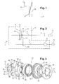
Figure 3 : Une représentation tridimensionnelle schématique en éclatée d'un dispositif de synchronisation, selon l'invention ; -
Figure 4 : Une représentation d'une vue en coupe longitudinale d'un dispositif de synchronisation, selon l'invention ; -
Figure 5 : Une vue en coupe agrandie partielle du dispositif de synchronisation selon lafigure 4 , et -
Figure 6 : Une représentation graphique d'un couple obtenu entre un moyeu et un pignon fou en fonction de la pression exercée, selon l'invention.
-
Figure 2 : A schematic representation of a traction chain of a vehicle, according to the invention; -
Figure 3 : A schematic three-dimensional representation exploded of a synchronization device, according to the invention; -
Figure 4 : A representation of a longitudinal sectional view of a synchronization device, according to the invention; -
Figure 5 : Partial enlarged sectional view of the synchronization device according to thefigure 4 , and -
Figure 6 : A graphical representation of a torque obtained between a hub and an idler gear according to the pressure exerted according to the invention.
La
La boîte de vitesses 4 est formée par un arbre primaire 6 et par un arbre secondaire 7. L'arbre primaire 6 est relié au moteur 2 et l'arbre secondaire 7 est relié aux roues 5 du véhicule. Un différentiel 8 assure une liaison entre l'arbre secondaire 7 et les roues du véhicule 5. L'arbre primaire 6 et l'arbre secondaire 7 sont reliés entre eux par au moins un engrenage 9 formant un rapport de vitesse.The
Chaque engrenage 9 comporte chacun une roue 10 solidaire en rotation d'un arbre et un pignon fou 11 monté sur l'autre arbre, la roue 10 et le pignon fou 11 engrenant entre eux. Dans l'exemple de la
Chaque engrenage comporte également un dispositif de synchronisation 13 pour synchroniser la vitesse de rotation de l'arbre primaire 6 avec celle de l'arbre secondaire 7. Ainsi, le moyeu 12 et le pignon fou 11 peuvent s'accoupler afin que le moteur via l'arbre primaire 6 et le moyeu 12 accélère ou décélère la vitesse du véhicule par augmentation ou diminution de la vitesse de rotation de l'arbre secondaire 7 via le pignon fou 11 et la roue 10.Each gear also includes a synchronizing
Les stators 14 et les rotors 15 sont disposés concentriquement les uns à l'intérieur des autres, en respectant une alternance stator/rotor du moyeu 12 vers le pignon 11.The
Les stators 14 sont liés en rotation au moyeu 12 par au moins un organe d'entraînement 20 formé par chacun des stators 14. Les rotors 15 sont liés en rotation au pignon fou 11 par au moins un autre organe d'entraînement 27 formé par chacun des rotors. L'organe d'entraînement 20 est logé dans une ouverture 21 formée au travers d'une jupe 22 du moyeu 12 assurant ainsi un maintien en rotation des stators 14 par rapport au moyeu 12. La jupe 22 est périphérique et plane. La jupe 22 s'étend dans un plan qui est perpendiculaire à un axe 23 d'allongement de l'arbre recevant le dispositif de synchronisation 13. Il y a autant d'ouvertures 21 qu'il y a d'organe d'entrainement 20 pour un stator 14 donné. L'autre organe d'entrainement 27 est logé dans une fente 28 formée au travers d'un flasque 29 lié en rotation au pignon fou 11 assurant également un maintien en rotation des rotors 15 par rapport au pignon fou 11. Le flasque 29 est situé dans un plan qui est perpendiculaire à l'axe 23 d'allongement. Comme pour les stators 14, il y a autant de fentes 28 qu'il y a d'autres organes d'entraînement 27 pour un rotor 15 donné.The
Lorsque le véhicule est à l'arrêt, moteur arrêté, aucun rapport de vitesse n'est engagé. Le pignon 11 n'est pas accouplé au moyeu 12, le moyeu 12 et les stators 14 d'une part, le pignon 11 et les rotors 15 d'autre part, sont statiques.When the vehicle is stopped with the engine stopped, no gear is engaged. The
Lorsque le véhicule est à l'arrêt, moteur en marche, aucun rapport de vitesse n'est engagé. Le pignon 11 n'est pas accouplé au moyeu 12, le moyeu 12 et les stators 14 tournent alors que le pignon 11 et les rotors 15 sont statiques.When the vehicle is stationary with the engine running, no gear is engaged. The
Lorsque le véhicule est en déplacement, le moteur en marche, un rapport de vitesse est engagé. Les bagues sont amenées au contact les unes par rapport aux autres suivant leur ordre de positionnement les unes par rapport aux autres. Les stators 14 et les rotors 15 sont liés en rotation et tournent à la même vitesse. C'est la synchronisation.When the vehicle is moving with the engine running, a gear is engaged. The rings are brought into contact with each other according to their order of positioning relative to each other. The
Le dispositif de synchronisation 13 comprend également un manchon 16 qui est disposé en liaison glissière avec le moyeu 12. Ce manchon 16 permet d'exercer un effort axial sur le stator 14 de plus grand diamètre, afin de générer un couple par friction de l'ensemble des stators 14 et des rotors 15 entraînant en rotation le pignon fou 11 avec le moyeu 12. Ce manchon 16 est commandé de manière connue par un mécanisme d'entraînement de type fourchette et d'un actionneur, par exemple hydraulique ou électrique. Le manchon 16 est lié en rotation au moyeu 12 mais est mobile axialement pour permettre l'accrochage du moyeu 12 avec le pignon fou 11.The
Lorsque tous les stators 14 et les rotors 15 sont liés les uns avec les autres par friction, le pignon fou 11 s'accouple au moyeu 12 par crabotage ou autre mécanisme d'accrochage. La vitesse de rotation de l'arbre secondaire 7 est donc liée à la vitesse de rotation de l'arbre primaire 6. La vitesse de rotation des roues est alors liée à la vitesse de rotation du moteur. Lorsque le moteur ralenti, la vitesse de rotation des roues est ralentie pour obtenir une décélération du véhicule. Lorsque le moteur accélère, la vitesse de rotation augmente pour obtenir une accélération du véhicule.When all the
La boîte de vitesses 4 comporte également un dispositif élastique 17. Ce dispositif élastique 17 permet un accouplement progressif des stators 14 avec les rotors 15.The
Selon l'invention, le dispositif élastique 17 forme une lame ressort 35 qui est montée fixe en rotation sur le moyeu 12,
La lame ressort 35 forme un anneau plat 30 et au moins une patte 18 élastique inclinée selon une direction radiale,
La patte radiale 18 forme une première surface 46 d'appui élastique qui s'étend radialement à partir d'une périphérie externe 44 de l'anneau 30 et en direction opposée à l'arbre sur lequel est montée la lame ressort 35,
La lame ressort 35 présente plusieurs pattes radiales 18 régulièrement reparties autour de l'anneau formé par le dispositif élastique 17. Dans l'exemple particulier de l'invention,
Les lumières 25 et les ouvertures 21 sont situées à des endroits différents. Plus particulièrement les lumières 25 et les ouvertures 21 sont formées les unes à la suite des autres en respectant une alternance lumière/ouverture.The
Le dispositif élastique 17 peut également comporter au moins un doigt de poussée 26,
La troisième surface d'appui 33 est également inclinée par rapport au plan perpendiculaire à l'axe 23.The
La deuxième surface 32 et la troisième surface 33 peuvent chacune être inclinée d'un angle qui est différent l'un de l'autre. La deuxième surface d'appui 32 est réalisée de telle manière que la patte radiale 18 épouse la forme de cette deuxième surface 32.The
Le doigt de poussée 26 est calé radialement à l'intérieur du moyeu 12, dans une lumière 25 du moyeu 12. En effet, le doigt de poussée 26 présente une extrémité interne 41 et une extrémité externe 42. L'extrémité interne 41 est proche de l'axe 23 tandis que l'extrémité externe 42 est éloignée de ce même axe 23. L'extrémité interne 41 est de forme arrondie et épouse une forme correspondante du moyeu 12. En effet, le moyeu 12 forme à un emplacement du doigt de poussée 26 un renfoncement de forme arrondie en correspondance du doigt de poussée 26. L'extrémité externe 42 du doigt poussée 26 est placée en appui contre un rebord périphérique 43 du moyeu 12.The
Dans un exemple non illustré, les bagues sont placées directement en appui élastiquement contre les pattes telles que 18 par la face opposée de la jupe 22 du moyeu 12. Les pattes 18 sont inclinées d'un angle permettant d'obtenir un décalage du positionnement des stators 14 et des rotors 15 les uns à la suite des autres le long de l'axe d'allongement 23. L'inclinaison des pattes 18 par rapport à un plan dans lequel s'étend l'anneau 30 dépend de la conception de la lame ressort à l'état libre puis comprimée. A titre indicatif, les pattes 18 sont inclinées d'un angle pouvant varier entre 15 et 25°.In an unillustrated example, the rings are placed directly bearing elastically against the tabs such as 18 by the opposite face of the
Il est prévu d'incliner une surface périphérique externe 36 d'un fût 37 formé par le moyeu 12 autour duquel sont placées les bagues. La surface périphérique externe 36 forme un cône dont la section la plus petite est située proche du pignon fou 11 et dont la section la plus grande est située éloignée du pignon fou 11. La surface périphérique externe 36 du fût 37 est réalisée de telle manière qu'une surface périphérique interne 38 de la bague de plus petit diamètre destinée à être en regard de cette surface externe 36 est inclinée parallèlement à la surface périphérique externe 36 du fût 37.It is intended to incline an outer
De même, une surface périphérique interne 39 du manchon 16 est inclinée tout en formant un cône dont la plus grande section est placée éloignée du pignon fou 11 contrairement à la plus faible section qui est située proche du pignon fou 11. Une surface externe 40 de la bague de plus grand diamètre étant destinée à être placée au regard de la surface interne 39 du manchon 16 est inclinée parallèlement à l'inclinaison de la surface interne 39 du manchon 16.Similarly, an inner
Claims (8)
Applications Claiming Priority (1)
| Application Number | Priority Date | Filing Date | Title |
|---|---|---|---|
| FR0953551A FR2946109B1 (en) | 2009-05-29 | 2009-05-29 | TRANSMISSION EQUIPPED WITH A SYNCHRONIZER WITH CONTROLLED COUPLE PASSAGE |
Publications (1)
| Publication Number | Publication Date |
|---|---|
| EP2256358A1 true EP2256358A1 (en) | 2010-12-01 |
Family
ID=41498772
Family Applications (1)
| Application Number | Title | Priority Date | Filing Date |
|---|---|---|---|
| EP10164184A Withdrawn EP2256358A1 (en) | 2009-05-29 | 2010-05-27 | Gearbox provided with a synchroniser with transition to controlled torque |
Country Status (2)
| Country | Link |
|---|---|
| EP (1) | EP2256358A1 (en) |
| FR (1) | FR2946109B1 (en) |
Cited By (2)
| Publication number | Priority date | Publication date | Assignee | Title |
|---|---|---|---|---|
| CN111102303A (en) * | 2019-12-31 | 2020-05-05 | 武汉协和齿环有限公司 | Multi-cone synchronizer ring assembly and synchronizer |
| CN113260799A (en) * | 2019-04-22 | 2021-08-13 | 日立建机株式会社 | Power transmission device |
Citations (3)
| Publication number | Priority date | Publication date | Assignee | Title |
|---|---|---|---|---|
| FR2804187A1 (en) | 2000-01-21 | 2001-07-27 | Renault | FRICTION CONE DEVICE AND COUPLING FOR GEARBOX |
| FR2815682A1 (en) | 2000-10-23 | 2002-04-26 | Peugeot Citroen Automobiles Sa | Gearbox synchroniser has pairs of indexing elements in form of guide teeth and grooves on ring and sleeve |
| EP2055974A1 (en) * | 2007-10-29 | 2009-05-06 | Peugeot Citroen Automobiles SA | Multi-cone synchronisation device designed to be installed on a gearbox shaft |
-
2009
- 2009-05-29 FR FR0953551A patent/FR2946109B1/en not_active Expired - Fee Related
-
2010
- 2010-05-27 EP EP10164184A patent/EP2256358A1/en not_active Withdrawn
Patent Citations (3)
| Publication number | Priority date | Publication date | Assignee | Title |
|---|---|---|---|---|
| FR2804187A1 (en) | 2000-01-21 | 2001-07-27 | Renault | FRICTION CONE DEVICE AND COUPLING FOR GEARBOX |
| FR2815682A1 (en) | 2000-10-23 | 2002-04-26 | Peugeot Citroen Automobiles Sa | Gearbox synchroniser has pairs of indexing elements in form of guide teeth and grooves on ring and sleeve |
| EP2055974A1 (en) * | 2007-10-29 | 2009-05-06 | Peugeot Citroen Automobiles SA | Multi-cone synchronisation device designed to be installed on a gearbox shaft |
Cited By (3)
| Publication number | Priority date | Publication date | Assignee | Title |
|---|---|---|---|---|
| CN113260799A (en) * | 2019-04-22 | 2021-08-13 | 日立建机株式会社 | Power transmission device |
| CN111102303A (en) * | 2019-12-31 | 2020-05-05 | 武汉协和齿环有限公司 | Multi-cone synchronizer ring assembly and synchronizer |
| CN111102303B (en) * | 2019-12-31 | 2021-09-17 | 武汉协和齿环有限公司 | Multi-cone synchronizer ring assembly and synchronizer |
Also Published As
| Publication number | Publication date |
|---|---|
| FR2946109B1 (en) | 2011-05-20 |
| FR2946109A1 (en) | 2010-12-03 |
Similar Documents
| Publication | Publication Date | Title |
|---|---|---|
| FR2625278A1 (en) | ACTUATOR FOR FRICTION SETTING DEVICE | |
| EP1939491B1 (en) | Gear with built-in overtorque protection | |
| EP2055974B1 (en) | Multi-cone synchronisation device designed to be installed on a gearbox shaft | |
| EP2256358A1 (en) | Gearbox provided with a synchroniser with transition to controlled torque | |
| EP1298340A1 (en) | Synchronizer for gearboxes of motor vehicles | |
| EP1118787B1 (en) | Gearbox coupling device with synchro ring | |
| EP2055976A1 (en) | High-capacity friction device for transmitting torque by sliding | |
| FR2803640A1 (en) | Synchronizing assembly for an automotive vehicle transmission includes an arrangement between two synchronizing rings, which has a central part cooperating with a reciprocally shaped part of the synchronizing unit | |
| EP3710298A1 (en) | Transmission device for a hybrid vehicle | |
| EP2159439B1 (en) | Friction device for transmitting torque | |
| EP3513088B1 (en) | System for the rotational decoupling of shafts | |
| EP1411257A1 (en) | Friction cone clutch for gearbox | |
| EP3084249B1 (en) | Stop for a gearbox sleeve comprising indentations for lubricating the synchronisers | |
| WO2018065679A1 (en) | Variable circumference gearing | |
| EP1026417B1 (en) | Synchroniser assembly for a vehicle tranmission | |
| FR2837532A1 (en) | STARTER EQUIPPED WITH A TORQUE ACCUMULATOR LAUNCHER | |
| WO2018114249A1 (en) | Module for a motor vehicle hybrid transmission | |
| WO2010049613A1 (en) | Friction cone coupling device for a gearbox with a lower ring centred on the hub | |
| FR2809784A1 (en) | Gear transmission for motor vehicle has free pinion selectively locked to shaft by sleeve with extendable locking dogs on radial surface | |
| FR2831861A1 (en) | Drive transmission for motor vehicle internal combustion engine, has starter-alternator controlled by clutches for additional power recuperation and drive functions | |
| FR3108699A3 (en) | Gearbox | |
| FR3022857A1 (en) | DEVICE FOR DRIVING TRAINING OF A HYBRID MOTOR VEHICLE AND METHOD USING SUCH A DEVICE. | |
| FR2549920A1 (en) | Disengageable driving device with balls or rollers | |
| FR3072438A3 (en) | VARIABLE CIRCUMFERENCE GEAR | |
| FR3080897A1 (en) | TRANSMISSION DEVICE FOR MOTOR VEHICLE |
Legal Events
| Date | Code | Title | Description |
|---|---|---|---|
| PUAI | Public reference made under article 153(3) epc to a published international application that has entered the european phase |
Free format text: ORIGINAL CODE: 0009012 |
|
| AK | Designated contracting states |
Kind code of ref document: A1 Designated state(s): AL AT BE BG CH CY CZ DE DK EE ES FI FR GB GR HR HU IE IS IT LI LT LU LV MC MK MT NL NO PL PT RO SE SI SK SM TR |
|
| AX | Request for extension of the european patent |
Extension state: BA ME RS |
|
| 17P | Request for examination filed |
Effective date: 20110527 |
|
| STAA | Information on the status of an ep patent application or granted ep patent |
Free format text: STATUS: THE APPLICATION HAS BEEN WITHDRAWN |
|
| 18W | Application withdrawn |
Effective date: 20120601 |