EP2256302B1 - Kanalwand für ein Gebläse eines Gasturbinenmotors - Google Patents
Kanalwand für ein Gebläse eines Gasturbinenmotors Download PDFInfo
- Publication number
- EP2256302B1 EP2256302B1 EP10161135A EP10161135A EP2256302B1 EP 2256302 B1 EP2256302 B1 EP 2256302B1 EP 10161135 A EP10161135 A EP 10161135A EP 10161135 A EP10161135 A EP 10161135A EP 2256302 B1 EP2256302 B1 EP 2256302B1
- Authority
- EP
- European Patent Office
- Prior art keywords
- duct wall
- fan
- intake section
- damper
- segment
- Prior art date
- Legal status (The legal status is an assumption and is not a legal conclusion. Google has not performed a legal analysis and makes no representation as to the accuracy of the status listed.)
- Ceased
Links
- 238000006073 displacement reaction Methods 0.000 claims abstract description 6
- 230000008878 coupling Effects 0.000 claims description 13
- 238000010168 coupling process Methods 0.000 claims description 13
- 238000005859 coupling reaction Methods 0.000 claims description 13
- 238000005192 partition Methods 0.000 claims description 11
- 238000004891 communication Methods 0.000 claims description 2
- 239000012634 fragment Substances 0.000 abstract description 8
- 230000006378 damage Effects 0.000 description 4
- 230000010355 oscillation Effects 0.000 description 4
- 238000010008 shearing Methods 0.000 description 3
- 238000005452 bending Methods 0.000 description 2
- 239000011248 coating agent Substances 0.000 description 2
- 238000000576 coating method Methods 0.000 description 2
- 238000013016 damping Methods 0.000 description 2
- 230000000694 effects Effects 0.000 description 2
- 239000000463 material Substances 0.000 description 2
- 230000005534 acoustic noise Effects 0.000 description 1
- 230000009471 action Effects 0.000 description 1
- 230000008901 benefit Effects 0.000 description 1
- 230000015572 biosynthetic process Effects 0.000 description 1
- 239000000945 filler Substances 0.000 description 1
- 238000012423 maintenance Methods 0.000 description 1
- 230000000116 mitigating effect Effects 0.000 description 1
- 230000000644 propagated effect Effects 0.000 description 1
- 230000008439 repair process Effects 0.000 description 1
- 230000000717 retained effect Effects 0.000 description 1
- 238000000926 separation method Methods 0.000 description 1
- 238000010408 sweeping Methods 0.000 description 1
- 230000007704 transition Effects 0.000 description 1
- XLYOFNOQVPJJNP-UHFFFAOYSA-N water Substances O XLYOFNOQVPJJNP-UHFFFAOYSA-N 0.000 description 1
Images

Classifications
-
- F—MECHANICAL ENGINEERING; LIGHTING; HEATING; WEAPONS; BLASTING
- F01—MACHINES OR ENGINES IN GENERAL; ENGINE PLANTS IN GENERAL; STEAM ENGINES
- F01D—NON-POSITIVE DISPLACEMENT MACHINES OR ENGINES, e.g. STEAM TURBINES
- F01D21/00—Shutting-down of machines or engines, e.g. in emergency; Regulating, controlling, or safety means not otherwise provided for
- F01D21/04—Shutting-down of machines or engines, e.g. in emergency; Regulating, controlling, or safety means not otherwise provided for responsive to undesired position of rotor relative to stator or to breaking-off of a part of the rotor, e.g. indicating such position
- F01D21/045—Shutting-down of machines or engines, e.g. in emergency; Regulating, controlling, or safety means not otherwise provided for responsive to undesired position of rotor relative to stator or to breaking-off of a part of the rotor, e.g. indicating such position special arrangements in stators or in rotors dealing with breaking-off of part of rotor
-
- F—MECHANICAL ENGINEERING; LIGHTING; HEATING; WEAPONS; BLASTING
- F01—MACHINES OR ENGINES IN GENERAL; ENGINE PLANTS IN GENERAL; STEAM ENGINES
- F01D—NON-POSITIVE DISPLACEMENT MACHINES OR ENGINES, e.g. STEAM TURBINES
- F01D25/00—Component parts, details, or accessories, not provided for in, or of interest apart from, other groups
- F01D25/04—Antivibration arrangements
- F01D25/06—Antivibration arrangements for preventing blade vibration
-
- F—MECHANICAL ENGINEERING; LIGHTING; HEATING; WEAPONS; BLASTING
- F01—MACHINES OR ENGINES IN GENERAL; ENGINE PLANTS IN GENERAL; STEAM ENGINES
- F01D—NON-POSITIVE DISPLACEMENT MACHINES OR ENGINES, e.g. STEAM TURBINES
- F01D5/00—Blades; Blade-carrying members; Heating, heat-insulating, cooling or antivibration means on the blades or the members
- F01D5/12—Blades
- F01D5/14—Form or construction
- F01D5/16—Form or construction for counteracting blade vibration
Definitions
- This invention relates to a duct wall for a fan of a gas turbine engine, and is particularly, although not exclusively, concerned with a duct wall structure which minimises damage to the engine in the event of detachment of all or part of a blade of the fan.
- the ducted fan comprises a fan rotor having an array of fan blades which rotate within a duct surrounding the fan rotor, to provide a substantial part of the thrust generated by the engine.
- the duct is defined by a fan casing which has an inner wall which is washed by the gas flow through the fan and an outer wall which is a structural casing.
- the inner wall is a continuation of the inlet annulus and merges into the fan casing annulus at a smooth transition at the front of the fan casing.
- Flutter is a potentially damaging phenomenon in which the aerodynamic forces acting on a fan blade act together with the resilience of the fan blade to set up an oscillation in the blade.
- work done by the fan blades has a damping action on the oscillation, causing the oscillations to decay.
- the oscillations can increase in amplitude and the resulting stresses can be very damaging to the blade.
- GB2090334 describes one such arrangement for mitigating flutter in fan blades of a gas turbine engine. It discloses a duct wall for a fan of a gas turbine engine, the duct wall comprising an intake section and an acoustic flutter damper.
- the acoustic flutter damper of GB2090334 comprises an array of tubes which are embedded in a filler material between a casing of the fan duct and an abradable material over which the fan blades pass.
- the tubes form cavities which are tuned to resonate at a known troublesome flutter frequency, so that, in the event of flutter arising, the resonating air in the tubes creates pressure waves which damp the flutter of the fan blades.
- duct casings are provided with containment means which are intended to absorb the energy of a detached blade or fragment, and to prevent, as far as possible, the ejection of the blade or fragment outside the engine.
- the duct wall defining the gas flow path thus commonly comprises a containment casing provided with containment measures, situated opposite the blade tips, so that the blade tips travel over the surface of the containment casing as the fan rotates.
- An intake section of the duct wall is typically rigidly secured to the containment casing, and extends forwards of the fan casing to provide an intake duct.
- the intake section and the containment casing are typically interconnected by bolts, which extend through abutting flanges on the intake section and the containment casing.
- FBO fan blade off
- the detached blade is thrown into contact with the inner face of the containment casing with considerable energy, and continues to rotate with the fan rotor, so travelling circumferentially around the duct wall.
- a circumferentially travelling deflection wave runs around the containment casing, and this applies substantial stress to the bolts holding the flanges together. This creates the danger that the bolts may shear, allowing the intake section of the duct wall to become detached from the containment casing, possibly enabling it to become entirely detached from the remainder of the engine.
- the containment casing may have a relatively thin wall section adjacent the flange of the containment casing, allowing the containment casing to flex at the reduced wall section, to reduce the stresses imposed on the securing bolts. Nevertheless the connection between the flanges remains rigid and so the possibility of the bolts shearing remains.
- a duct wall for a fan of a gas turbine engine comprising an intake section and a containment casing which are connected together by coupling elements extending between respective faces of the intake section and the containment casing, the faces being spaced apart by an acoustic flutter damper which extends between the faces whereby radial displacement of a region of the containment casing face relative to the opposite region of the intake section face is accommodated by displacement and/or deformation of the acoustic flutter damper.
- the acoustic flutter damper provides an axial separation between the opposed faces of the intake section and the containment casing, enabling these faces to move radially relatively to each other in an FBO event. Since the faces are spaced apart, the coupling elements, such as bolts are able to tilt, reducing the likelihood of them shearing, so enabling the intake section and the containment casing to remain attached to each other.
- the acoustic flutter damper may comprise a circumferential array of damper segments extending at least partially, and more probably entirely, around the circumference of the duct wall.
- Each segment may comprise a skin defining a chamber containing an internal structure which defines radially extending passages which open at a surface of the duct wall, for example through a perforated partition.
- the passages thus provide resonant chambers which give the fan duct wall the correct acoustic properties to avoid flutter of the blades of the fan at certain key operating conditions.
- Each segment may have an external support element adapted to receive a respective one of the coupling elements.
- Each segment may have two of the support elements disposed on opposite circumferential sides of the segment, the support elements on each side being axially offset from each other so that bores of the respective support elements of adjacent segments are aligned to receive a common one of the coupling elements.
- Each segment may have a retaining element cooperating with a formation provided in at least one of the faces of the intake section and the containment casing.
- Each segment may have a flared configuration, as viewed in the axial direction of the fan, so that the segment becomes circumferentially wider in the radially inwards direction.
- each segment may comprise interlocking or edge joined partitions which define the passages.
- the partitions and the skin may have drain means providing communication between the passages and the exterior of the skin.
- the coupling elements may comprise releasable fasteners cooperating with flanges on which the faces are provided.
- the-control elements may be formed integrally with, or otherwise permanently secured to, the intake section or the containment casing.
- the present invention also provides a gas turbine engine comprising a fan assembly having a duct casing including a duct wall as defined above.
- Figure 1 shows part of a duct casing which includes a duct wall 2 comprising an intake section 4 and a containment casing 6.
- the intake section 4 is a twin-walled panel containing an acoustic filling (not shown) having a perforate skin on the gas-washed surface.
- Figure 1 shows part of a nacelle outer cowl surface 8 which extends to the front of the duct casing (to the left in Figure 1 ), and curves smoothly inwards relatively to the fan axis (which is not shown in Figure 1 but is situated below the Figure).
- the cowl surface 8 is braced with respect to the intake section 4 by a sealed bulkhead partition 10 provided with an aperture 12 for passing systems.
- the containment casing 6 carries a honeycomb acoustic structure 14, which is covered by an abradable coating 16 across which fan blades, represented by a leading edge 18, sweep when the engine is operating.
- the intake section 4 is provided with a flange 20, and the containment casing 6 is provided with a flange 22.
- the flanges 20, 22 have oppositely disposed faces 24, 26, and an acoustic flutter damper 28 is positioned between these faces 24, 26.
- the acoustic flutter damper 28 projects into a cavity 32 defined between the intake section 4 and the containment casing 6, the radially inner end 30 itself terminating flush with the gas washed surfaces of the intake section 4 and the containment casing 6.
- the cavity 32 contains an acoustic liner structure.
- the greater part of the radial extent of the acoustic flutter damper 28 projects radially outwardly of the duct wall 2. Because the acoustic flutter damper 28 is situated between the faces 24, 26 of the flanges 20, 22, the intake section 4 and the containment casing 6 are axially spaced apart from each other, rather than being directly connected together at the flanges 20, 22 as in known duct casings.
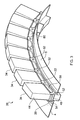
- the acoustic flutter damper 28 is shown in more detail in Figures 2 and 3 . It will be appreciated from Figure 3 that the acoustic flutter damper 28 comprises an array of segments 34. The segments 34 are shown identical to each other, but are separately retained between the flanges 20, 22.
- the number of segments 34 may vary in different embodiments of the invention, according to a number of factors including the size of the gas turbine engine and the sophistication of its design. In large engines, there may be more than fifty of the segments 34. For example, in the embodiment shown in Figure 3 fifty-seven segments are arranged around the whole circumference of the duct casing; Figure 3 therefore shows slightly less than one-seventh of the whole duct casing. In smaller or less sophisticated engines (for example, model engines) there may be far fewer segments, perhaps as few as four in some embodiments.
- FIG. 2 shows one of the segments 34.
- Each segment 34 comprises a skin 36, within which is disposed an internal structure comprising a set of interlocking or edge-joined partitions 38 which define, within the skin 36, a series of rectangular cross-section passages which extend lengthwise of the segment 34 (ie radially with respect to the fan axis).
- each segment is rectangular in a cross-section taken perpendicular to the radial direction, and the skin 36 extends around the rectangular periphery of the segment 34, and over the radially outer end of the segment 34.
- Each passage 40 is therefore closed around its sides and at its radially outer end, and communicates at its radially inner end, through a perforated partition 42, with the interior of the duct at the face 30.
- the partitions 38 and the skin 36 are provided with drain means in the form of small holes 64 which enable any water entering the segments 34 through the perforated panels 42 to drain out of the engine.
- each segment 34 is flared, so that they diverge from each other in the radially inwards direction.
- the effect of this is that, although adjacent segments 34 abut one another at their radially inner ends 30, they are spaced apart from one another at positions away from their ends 30 by a greater distance than they would be if they had a constant cross-sectional area along their length.
- Each segment 34 has, on each of its circumferential side faces 44, a support element 46.
- the support element 46 is situated at a position approximately 20% to 30% (depending on the depth of flutter damping required but typically approximately 25-40 mm radially outboard of the casing line) along the length of the segment 34, from the radially inner end 30.
- Each support element 46 extends, in the axial direction, over only approximately one half of the axial width of the segment 34, and, as will be appreciated from Figure 2 , the support elements 46 on opposite sides of the segment 34 are axially offset from each other so that the one further to the left as seen in Figure 2 is positioned towards the containment casing 6, while the one further to the right in Figure 2 is situated towards the intake section 4.
- Each support element 46 has a bore 48.
- the support elements 46 of adjacent segments 34 fit together one behind the other in the axial direction, so that the bores 48 of the two support elements 46 are aligned.
- the aligned bores 48 receive coupling elements in the form of bolts (identified by centrelines 50 in Figure 1 ) which pass through openings 52 in the flange 22, through the aligned bores 48 and through an opening 54 in the flange 20.
- the bolts 50 thus hold together the flanges 20, 22 and consequently the intake section 4 and the containment casing 6, while passing between adjacent segments 34 of the acoustic flutter damper 28.
- Each segment 34 is also provided on its circumferential side faces 44 with a retaining element 56, which may be formed integrally with the support element 46.
- Each retaining element 56 has a pair of oppositely directed lugs 58 which project axially beyond the periphery of the segment 34. As shown in Figure 3 , the lugs 58 engage grooves formed in the flanges 20, 22, and serve to retain the segments 34 in the radial direction with respect to the intake-section 4 and the containment casing 6.
- the flange 22 is scalloped by means of cut-away regions 60 between the regions of the flange 22 in which the openings 52 are provided. This configuration of the flange 22 is for weight-saving reasons, and a similar configuration may be employed for the flange 20.
- the fan blades 18 rotate within the duct defined by the duct wall 2, with the tips of the fan blades 18 sweeping across the abradable coating 16. Acoustic noise at audible wavelengths generated by the fan is absorbed in the filling of the intake section 4 and the acoustic structure in the cavity 32. If incipient flutter develops, the fluttering blades 18 generate low frequency pressure waves which are propagated forwards, ie to the left in Figure 1 , and enter the segments 34 of the acoustic flutter damper 28 through the perforated partition 42. The pressure waves thus travel up the individual passages 40 which are tuned, by adjustment of their length, in accordance with the expected frequency of the vibration experienced at the blades 18.
- Acoustic flutter dampers of the kind shown in the Figures are referred to as "deep liners" by virtue of the substantial length of the passages 40, by comparison with the shorter passages in the acoustic liner 4 and the cavity 32, which are accommodated in the relatively shallow space between the inner and outer skins of the intake section 4 and the front of the containment casing 6.
- a fan blade 18, or a fragment of such a blade becomes detached from the rotor, it will be impelled outwardly under centrifugal force, and will pass through the abradable lining 16 into the honeycomb acoustic structure 14. Since an ejected blade or fragment will have a significant component of momentum in the circumferential direction, it will travel around the containment casing 6, generating a circumferential deflection wave of significant amplitude. In other words, the containment casing 6 is deflected radially outwardly to a substantial extent, and the flange 22 will be locally deflected relatively to the flange 20.
- the segments 34 in the region of the deflection may be crushed or expanded as well as being tilted. Such deformation of the segments 34 absorbs some of the energy transferred from the dislodged blade 18 or fragment and, again, reduces the possibility of destruction of the bolts 50.
- the torsional stiffness of the segments 34 can be adjusted by appropriate design to provide load transference during deflection of the containment casing 6. Since a detached blade or fragment creates a travelling deflection wave, adjacent bolts 50 will be deflected at different angles from each other, causing the segments 34 between them to be twisted. If the segments 34 are of adequate torsional stiffness, they will thus transfer deflection loads from one bolt 50 to the next so reducing local bolt bending.
- the tolerance and profile between the lugs 58 and the grooves in flanges 22 and 24 can be adjusted to allow the interlocking segments to rotate to some extent around the bolt centreline 50 and therefore allow the individual segments to follow the local deflection wave which passes around the circumference of the flange during an FBO event.
- the individual segments 34 are connected by the bolts 50 passing through the bores 48, 52, 54, like the links in a bicycle chain, so that the travelling wave from the FBO impact raises and lowers the segments individually, causing them to locally roll about the bolt axes, and "ride" the wave.
- the deep liner thus has a low hoop bending stiffness, and does not try to "fight" the FBO wave.
- the gaps shown at the outer radius between the segments 34 open and close as the wave passes, and should be sufficient to avoid the segments "chocking" against each other, at the troughs of the wave.
- the panel 10 meets the intake section 4 at a smooth curve 62 of relatively large radius. This curve enables the intake section 4 to deflect relatively to the skin 8 in a manner which minimises damage to other parts of the duct case under the deflections which occur during an FBO event.
- each passage 40 may be approximately 250 mm and its axial width between the flanges 20, 22 may be approximately 50 mm.
- the flared configuration of the circumferential side faces 44 of each segment 34 means that adequate space is provided between adjacent segments 34 to accommodate relatively larger-diameter bolts 50 at a given radial position than would be the case if the circumferential side faces 44 of each segment 34 were straight and parallel to each other. Also, it is advantageous for the bolts to be situated outside the skin 36, to avoid interference with the pressure waves generated within the passages 40.
- the positioning of the acoustic flutter damper 28 between the flanges 20 and 22 provides the advantage that the inlet to the passages 40, at the perforated partition 42, is positioned relatively close to the blades 18, where the energy to be damped is generated.
- the acoustic flutter damper segments 34 are able to project radially, with little constraint on the radial length of the passages 40, enabling proper tuning of the damper 28 to the frequencies expected during flutter of the blades 18.
- any of the segments 34 are damaged, it is possible to replace them individually, without needing to replace the entire acoustic flutter damper 28. This consequently reduces repair and maintenance costs, as well as transportation costs, since the individual segments 34 can be packed in relatively small containers, whereas a complete acoustic flutter damper has a substantial diameter, and would require specialised handling.
Landscapes
- Engineering & Computer Science (AREA)
- Mechanical Engineering (AREA)
- General Engineering & Computer Science (AREA)
- Structures Of Non-Positive Displacement Pumps (AREA)
- Rigid Pipes And Flexible Pipes (AREA)
Claims (14)
- Kanalwand (2) für ein Gebläse (18) eines Gasturbinentriebwerks, wobei die Kanalwand (2) einen Einlassabschnitt (4) und eine akustische Flatterschwingungs-Dämpfungseinrichtung (28) umfasst, dadurch gekennzeichnet, dass die Kanalwand weiterhin einen Sicherheitsummantelungs-Abschnitt (6) umfasst, wobei der Einlassabschnitt (4) und der Sicherheitsummantelungs-Abschnitt (6) miteinander durch Kupplungselemente (50) verbunden sind, die sich zwischen jeweiligen Stirnflächen (24, 26) des Einlassabschnittes (4) und des Sicherheitsummantelungs-Abschnittes (6) erstrecken, wobei die Stirnflächen (24, 26) durch die akustische Flatterschwingungs-Dämpfungseinrichtung (28) auf Abstand gehalten werden, die sich zwischen den Stirnflächen (24, 26) erstreckt, wobei eine radiale Bewegung eines Bereiches der Stirnfläche (26) des Sicherheitsummantelungs-Abschnitts gegenüber dem gegenüberliegenden Bereich der Einlassabschnitt-Stirnfläche (24) durch eine Bewegung und/oder Verformung der akustischen Flatterschwingungs-Dämpfungseinrichtung (28) aufgenommen wird.
- Kanalwand nach Anspruch 1, dadurch gekennzeichnet, dass die akustische Flatterschwingungs-Dämpfungseinrichtung (28) eine in Umfangsrichtung angeordnete Gruppe von Dämpfungseinrichtungs-Segmenten (34) umfasst.
- Kanalwand nach Anspruch 2, dadurch gekennzeichnet, dass jedes Dämpfungseinrichtungs-Segment (34) eine Aussenhaut (36) aufweist, die eine Kammer bildet, die eine interne Struktur (38) enthält, die sich in Radialrichtung erstreckende Kanäle (40) bildet, die sich an einer Oberfläche der Kanalwand (24) durch eine perforierte Trennwand (42) öffnen.
- Kanalwand nach Anspruch 3, dadurch gekennzeichnet, dass die interne Struktur ineinander verriegelte oder keilverbundene Unterteilungen (38) umfasst, die die Kanäle (40) bilden.
- Kanalwand nach Anspruch 4, dadurch gekennzeichnet, dass Auslasseinrichtungen (64) eine Verbindung zwischen den Kanälen (40) und der Aussenseite der Aussenhaut (36) bilden.
- Kanalwand nach einem der Ansprüche 2 bis 5, dadurch gekennzeichnet, dass jedes Segment ein äußeres Halterungselement (46) zur Aufnahme eines entsprechenden einen der Kupplungselemente (50) aufweist.
- Kanalwand nach Anspruch 6, dadurch gekennzeichnet, dass jedes Halterungselement (46) mit einer Bohrung (48) zur Aufnahme des jeweiligen Kupplungselementes (50) versehen ist wobei entgegengesetzte Umfangsseiten (44) jedes Segmentes (34) jeweilige Halterungselemente (46) aufweisen, die in Axialrichtung voneinander versetzt sind, wodurch Bohrungen (48) der Halterungselemente (46) benachbarter Segmente (34) miteinander ausgerichtet sind, um ein gemeinsames Kupplungselement (50) aufzunehmen.
- Kanalwand nach Anspruch 7, dadurch gekennzeichnet, dass die benachbarten Segmente (34) eine begrenzte Schwenkbewegung bezüglich einander um das jeweilige gemeinsame Kupplungselement (50) ausführen können.
- Kanalwand nach einem der Ansprüche 2 bis 8, dadurch gekennzeichnet, dass jedes Segment (34) ein Halteelement (56) aufweist, das in eine in Umfangsrichtung verlaufende Nut in zumindest einer der Stirnflächen (24, 26) des Einlassabschnittes (4) und des Sicherheitsummantelungs-Abschnittes (6) eingreift.
- Kanalwand nach einem der Ansprüche 2 bis 9, dadurch gekennzeichnet, dass jedes Segment bei Betrachtung in Axialrichtung des Gebläses (18) in einer sich in Radialrichtung nach innen erstreckenden Richtung erweitert ist.
- Kanalwand nach einem der Ansprüche 2 bis 9, dadurch gekennzeichnet, dass zumindest fünfzig der Segmente vorgesehen sind.
- Kanalwand nach einem der vorhergehenden Ansprüche, dadurch gekennzeichnet, dass die Kupplungselemente (50) lösbare Befestigungsmittel umfassen, die mit Flanschen (20, 22) zusammenwirken, auf denen die Stirnflächen (24, 26) vorgesehen sind.
- Kanalwand nach einem der Ansprüche 1 bis 11, dadurch gekennzeichnet, dass die Kupplungselemente (50) dauerhaft an dem Einlassabschnitt (4) oder dem Sicherheitsummantelungs-Abschnitt (6) befestigt sind.
- Gasturbinentriebwerk mit einer Gebläseanordnung, die ein Kanalgehäuse umfasst, das eine Kanalwand (2) nach einem der hergehenden Ansprüche einschließt.
Applications Claiming Priority (1)
| Application Number | Priority Date | Filing Date | Title |
|---|---|---|---|
| GBGB0907580.5A GB0907580D0 (en) | 2009-05-05 | 2009-05-05 | A duct wall for a fan or a gas turbine engine |
Publications (2)
| Publication Number | Publication Date |
|---|---|
| EP2256302A1 EP2256302A1 (de) | 2010-12-01 |
| EP2256302B1 true EP2256302B1 (de) | 2012-03-28 |
Family
ID=40792158
Family Applications (1)
| Application Number | Title | Priority Date | Filing Date |
|---|---|---|---|
| EP10161135A Ceased EP2256302B1 (de) | 2009-05-05 | 2010-04-27 | Kanalwand für ein Gebläse eines Gasturbinenmotors |
Country Status (4)
| Country | Link |
|---|---|
| US (1) | US8506234B2 (de) |
| EP (1) | EP2256302B1 (de) |
| AT (1) | ATE551498T1 (de) |
| GB (1) | GB0907580D0 (de) |
Families Citing this family (15)
| Publication number | Priority date | Publication date | Assignee | Title |
|---|---|---|---|---|
| DE102011005025A1 (de) * | 2011-03-03 | 2012-09-06 | Siemens Aktiengesellschaft | Resonatorschalldämpfer für eine radiale Strömungsmaschine, insbesondere für einen Radialverdichter |
| US9664062B2 (en) * | 2011-12-08 | 2017-05-30 | Siemens Energy, Inc. | Gas turbine engine with multiple component exhaust diffuser operating in conjunction with an outer case ambient external cooling system |
| US9534505B2 (en) | 2012-07-23 | 2017-01-03 | United Technologies Corporation | Integrated nacelle inlet and metallic fan containment case |
| DE102014218350A1 (de) | 2014-09-12 | 2016-03-17 | Rolls-Royce Deutschland Ltd & Co Kg | Schalldämpfende Anordnung für eine Triebwerksgondel und Triebwerksgondel mit einer solchen Anordnung |
| US10422280B2 (en) | 2017-03-07 | 2019-09-24 | United Technologies Corporation | Fan flutter suppression system |
| US10539156B2 (en) | 2017-03-07 | 2020-01-21 | United Technologies Corporation | Variable displacement flutter damper for a turbofan engine |
| US10415506B2 (en) | 2017-03-07 | 2019-09-17 | United Technologies Corporation | Multi degree of freedom flutter damper |
| US10612464B2 (en) | 2017-03-07 | 2020-04-07 | United Technologies Corporation | Flutter inhibiting intake for gas turbine propulsion system |
| US10428765B2 (en) * | 2017-03-07 | 2019-10-01 | United Technologies Corporation | Asymmetric multi degree of freedom flutter damper |
| US10619566B2 (en) | 2017-03-07 | 2020-04-14 | United Technologies Corporation | Flutter damper for a turbofan engine |
| US10941708B2 (en) | 2017-03-07 | 2021-03-09 | Raytheon Technologies Corporation | Acoustically damped gas turbine engine |
| US10428685B2 (en) | 2017-03-07 | 2019-10-01 | United Technologies Corporation | Flutter inhibiting intake for gas turbine propulsion system |
| EP3372813B8 (de) * | 2017-03-07 | 2021-04-07 | Raytheon Technologies Corporation | Flatterdämpfer mit mehreren freiheitsgraden |
| EP3372814B1 (de) * | 2017-03-07 | 2022-05-04 | Raytheon Technologies Corporation | Asymmetrischer flatterdämpfer mit mehreren freiheitsgraden |
| FR3083214A1 (fr) * | 2018-06-28 | 2020-01-03 | Airbus Operations | Nacelle d'un ensemble propulsif d'aeronef comportant une pluralite d'elements amortisseurs entre une partie avant et une partie principale, et ensemble propulsif d'aeronef associe |
Family Cites Families (9)
| Publication number | Priority date | Publication date | Assignee | Title |
|---|---|---|---|---|
| GB2090334B (en) | 1980-12-29 | 1983-11-16 | Rolls Royce | Damping flutter of ducted fans |
| US4484856A (en) * | 1981-12-21 | 1984-11-27 | United Technologies Corporation | Containment structure |
| US4934899A (en) | 1981-12-21 | 1990-06-19 | United Technologies Corporation | Method for containing particles in a rotary machine |
| US6206631B1 (en) | 1999-09-07 | 2001-03-27 | General Electric Company | Turbomachine fan casing with dual-wall blade containment structure |
| GB2365945B (en) | 2000-08-16 | 2004-02-11 | Rolls Royce Plc | A vibration damping system and a method of damping vibrations |
| US6499940B2 (en) | 2001-03-19 | 2002-12-31 | Williams International Co., L.L.C. | Compressor casing for a gas turbine engine |
| GB0410778D0 (en) | 2004-05-13 | 2004-06-16 | Rolls Royce Plc | Blade arrangement |
| FR2903732B1 (fr) | 2006-07-12 | 2008-09-12 | Airbus France Sas | Entree d'air pour turbomoteur d'aeronef. |
| US7721525B2 (en) | 2006-07-19 | 2010-05-25 | Rohr, Inc. | Aircraft engine inlet having zone of deformation |
-
2009
- 2009-05-05 GB GBGB0907580.5A patent/GB0907580D0/en not_active Ceased
-
2010
- 2010-04-27 EP EP10161135A patent/EP2256302B1/de not_active Ceased
- 2010-04-27 AT AT10161135T patent/ATE551498T1/de active
- 2010-04-27 US US12/768,041 patent/US8506234B2/en not_active Expired - Fee Related
Also Published As
| Publication number | Publication date |
|---|---|
| US20100284788A1 (en) | 2010-11-11 |
| US8506234B2 (en) | 2013-08-13 |
| ATE551498T1 (de) | 2012-04-15 |
| GB0907580D0 (en) | 2009-06-10 |
| EP2256302A1 (de) | 2010-12-01 |
Similar Documents
| Publication | Publication Date | Title |
|---|---|---|
| EP2256302B1 (de) | Kanalwand für ein Gebläse eines Gasturbinenmotors | |
| EP2273076B1 (de) | Kanalwand für ein Gebläse eines Gasturbinenmotors | |
| JP5425908B2 (ja) | タービンエンジンのナセルの内壁 | |
| US9359901B2 (en) | Aerofoil assembly | |
| US4531362A (en) | Aerodynamic damping of vibrations in rotor blades | |
| US9097179B2 (en) | Damping assembly | |
| EP2105597B1 (de) | Akustische Verkleidungspanele für ein Bläsertriebwerk | |
| EP2336500B1 (de) | Verfahren zur herstellung einer einlassvorrichtung eines flugzeugtriebwerkes | |
| EP2767676B1 (de) | Rückhaltesystem für Gebläse, zugehörige Gebläseanordnung und Gasturbinentriebwerk | |
| US9683490B2 (en) | Pivoting fan track liner for blade retainment | |
| RU2518719C2 (ru) | Воздушый стартер для турбодвигателя | |
| EP0965731A2 (de) | Berstschutzring für eine Gasturbine | |
| CA2021088A1 (en) | Damper assembly for a strut in a jet propulsion engine | |
| JPH0792002B2 (ja) | ガスタービンエンジン支柱用のダンパアセンブリ | |
| US20110138769A1 (en) | Fan containment case | |
| US8479877B2 (en) | Gas-turbine exhaust cone with three-dimensionally profiled partition wall and plate-type wall element | |
| US7806364B1 (en) | Containment system for a gas turbine engine | |
| US7445421B2 (en) | Fan duct blade containment assembly | |
| EP1722069A1 (de) | Gasturbine | |
| CN110654554A (zh) | 短舱以及包括短舱的飞行器推进组件 | |
| EP3901413B1 (de) | Schaufeln mit spitzentaschen | |
| EP3957825B1 (de) | Turbinenschaufel mit reibungs- und prallschwingungsdämpfungselementen | |
| EP4644666A1 (de) | Berstschutzring für gasturbinenmotor | |
| US20080063522A1 (en) | Array of components | |
| CA3271810A1 (en) | Containment ring for gas turbine engine |
Legal Events
| Date | Code | Title | Description |
|---|---|---|---|
| PUAI | Public reference made under article 153(3) epc to a published international application that has entered the european phase |
Free format text: ORIGINAL CODE: 0009012 |
|
| AK | Designated contracting states |
Kind code of ref document: A1 Designated state(s): AT BE BG CH CY CZ DE DK EE ES FI FR GB GR HR HU IE IS IT LI LT LU LV MC MK MT NL NO PL PT RO SE SI SK SM TR |
|
| AX | Request for extension of the european patent |
Extension state: AL BA ME RS |
|
| 17P | Request for examination filed |
Effective date: 20110310 |
|
| GRAP | Despatch of communication of intention to grant a patent |
Free format text: ORIGINAL CODE: EPIDOSNIGR1 |
|
| RIC1 | Information provided on ipc code assigned before grant |
Ipc: F01D 5/16 20060101ALI20111031BHEP Ipc: F01D 25/06 20060101ALI20111031BHEP Ipc: F01D 21/04 20060101AFI20111031BHEP |
|
| GRAS | Grant fee paid |
Free format text: ORIGINAL CODE: EPIDOSNIGR3 |
|
| GRAA | (expected) grant |
Free format text: ORIGINAL CODE: 0009210 |
|
| AK | Designated contracting states |
Kind code of ref document: B1 Designated state(s): AT BE BG CH CY CZ DE DK EE ES FI FR GB GR HR HU IE IS IT LI LT LU LV MC MK MT NL NO PL PT RO SE SI SK SM TR |
|
| REG | Reference to a national code |
Ref country code: GB Ref legal event code: FG4D |
|
| REG | Reference to a national code |
Ref country code: CH Ref legal event code: EP |
|
| REG | Reference to a national code |
Ref country code: AT Ref legal event code: REF Ref document number: 551498 Country of ref document: AT Kind code of ref document: T Effective date: 20120415 |
|
| REG | Reference to a national code |
Ref country code: IE Ref legal event code: FG4D |
|
| REG | Reference to a national code |
Ref country code: DE Ref legal event code: R096 Ref document number: 602010001175 Country of ref document: DE Effective date: 20120524 |
|
| REG | Reference to a national code |
Ref country code: NL Ref legal event code: VDEP Effective date: 20120328 |
|
| PG25 | Lapsed in a contracting state [announced via postgrant information from national office to epo] |
Ref country code: NO Free format text: LAPSE BECAUSE OF FAILURE TO SUBMIT A TRANSLATION OF THE DESCRIPTION OR TO PAY THE FEE WITHIN THE PRESCRIBED TIME-LIMIT Effective date: 20120628 Ref country code: HR Free format text: LAPSE BECAUSE OF FAILURE TO SUBMIT A TRANSLATION OF THE DESCRIPTION OR TO PAY THE FEE WITHIN THE PRESCRIBED TIME-LIMIT Effective date: 20120328 Ref country code: LT Free format text: LAPSE BECAUSE OF FAILURE TO SUBMIT A TRANSLATION OF THE DESCRIPTION OR TO PAY THE FEE WITHIN THE PRESCRIBED TIME-LIMIT Effective date: 20120328 |
|
| LTIE | Lt: invalidation of european patent or patent extension |
Effective date: 20120328 |
|
| PG25 | Lapsed in a contracting state [announced via postgrant information from national office to epo] |
Ref country code: GR Free format text: LAPSE BECAUSE OF FAILURE TO SUBMIT A TRANSLATION OF THE DESCRIPTION OR TO PAY THE FEE WITHIN THE PRESCRIBED TIME-LIMIT Effective date: 20120629 Ref country code: LV Free format text: LAPSE BECAUSE OF FAILURE TO SUBMIT A TRANSLATION OF THE DESCRIPTION OR TO PAY THE FEE WITHIN THE PRESCRIBED TIME-LIMIT Effective date: 20120328 Ref country code: FI Free format text: LAPSE BECAUSE OF FAILURE TO SUBMIT A TRANSLATION OF THE DESCRIPTION OR TO PAY THE FEE WITHIN THE PRESCRIBED TIME-LIMIT Effective date: 20120328 |
|
| REG | Reference to a national code |
Ref country code: AT Ref legal event code: MK05 Ref document number: 551498 Country of ref document: AT Kind code of ref document: T Effective date: 20120328 |
|
| PG25 | Lapsed in a contracting state [announced via postgrant information from national office to epo] |
Ref country code: CY Free format text: LAPSE BECAUSE OF FAILURE TO SUBMIT A TRANSLATION OF THE DESCRIPTION OR TO PAY THE FEE WITHIN THE PRESCRIBED TIME-LIMIT Effective date: 20120328 |
|
| PG25 | Lapsed in a contracting state [announced via postgrant information from national office to epo] |
Ref country code: PL Free format text: LAPSE BECAUSE OF FAILURE TO SUBMIT A TRANSLATION OF THE DESCRIPTION OR TO PAY THE FEE WITHIN THE PRESCRIBED TIME-LIMIT Effective date: 20120328 Ref country code: BE Free format text: LAPSE BECAUSE OF FAILURE TO SUBMIT A TRANSLATION OF THE DESCRIPTION OR TO PAY THE FEE WITHIN THE PRESCRIBED TIME-LIMIT Effective date: 20120328 Ref country code: CZ Free format text: LAPSE BECAUSE OF FAILURE TO SUBMIT A TRANSLATION OF THE DESCRIPTION OR TO PAY THE FEE WITHIN THE PRESCRIBED TIME-LIMIT Effective date: 20120328 Ref country code: EE Free format text: LAPSE BECAUSE OF FAILURE TO SUBMIT A TRANSLATION OF THE DESCRIPTION OR TO PAY THE FEE WITHIN THE PRESCRIBED TIME-LIMIT Effective date: 20120328 Ref country code: SE Free format text: LAPSE BECAUSE OF FAILURE TO SUBMIT A TRANSLATION OF THE DESCRIPTION OR TO PAY THE FEE WITHIN THE PRESCRIBED TIME-LIMIT Effective date: 20120328 Ref country code: RO Free format text: LAPSE BECAUSE OF FAILURE TO SUBMIT A TRANSLATION OF THE DESCRIPTION OR TO PAY THE FEE WITHIN THE PRESCRIBED TIME-LIMIT Effective date: 20120328 Ref country code: IS Free format text: LAPSE BECAUSE OF FAILURE TO SUBMIT A TRANSLATION OF THE DESCRIPTION OR TO PAY THE FEE WITHIN THE PRESCRIBED TIME-LIMIT Effective date: 20120728 Ref country code: SI Free format text: LAPSE BECAUSE OF FAILURE TO SUBMIT A TRANSLATION OF THE DESCRIPTION OR TO PAY THE FEE WITHIN THE PRESCRIBED TIME-LIMIT Effective date: 20120328 |
|
| PG25 | Lapsed in a contracting state [announced via postgrant information from national office to epo] |
Ref country code: PT Free format text: LAPSE BECAUSE OF FAILURE TO SUBMIT A TRANSLATION OF THE DESCRIPTION OR TO PAY THE FEE WITHIN THE PRESCRIBED TIME-LIMIT Effective date: 20120730 Ref country code: MC Free format text: LAPSE BECAUSE OF NON-PAYMENT OF DUE FEES Effective date: 20120430 Ref country code: SK Free format text: LAPSE BECAUSE OF FAILURE TO SUBMIT A TRANSLATION OF THE DESCRIPTION OR TO PAY THE FEE WITHIN THE PRESCRIBED TIME-LIMIT Effective date: 20120328 |
|
| PG25 | Lapsed in a contracting state [announced via postgrant information from national office to epo] |
Ref country code: AT Free format text: LAPSE BECAUSE OF FAILURE TO SUBMIT A TRANSLATION OF THE DESCRIPTION OR TO PAY THE FEE WITHIN THE PRESCRIBED TIME-LIMIT Effective date: 20120328 Ref country code: DK Free format text: LAPSE BECAUSE OF FAILURE TO SUBMIT A TRANSLATION OF THE DESCRIPTION OR TO PAY THE FEE WITHIN THE PRESCRIBED TIME-LIMIT Effective date: 20120328 Ref country code: NL Free format text: LAPSE BECAUSE OF FAILURE TO SUBMIT A TRANSLATION OF THE DESCRIPTION OR TO PAY THE FEE WITHIN THE PRESCRIBED TIME-LIMIT Effective date: 20120328 |
|
| PLBE | No opposition filed within time limit |
Free format text: ORIGINAL CODE: 0009261 |
|
| STAA | Information on the status of an ep patent application or granted ep patent |
Free format text: STATUS: NO OPPOSITION FILED WITHIN TIME LIMIT |
|
| PG25 | Lapsed in a contracting state [announced via postgrant information from national office to epo] |
Ref country code: IT Free format text: LAPSE BECAUSE OF FAILURE TO SUBMIT A TRANSLATION OF THE DESCRIPTION OR TO PAY THE FEE WITHIN THE PRESCRIBED TIME-LIMIT Effective date: 20120328 Ref country code: MK Free format text: LAPSE BECAUSE OF FAILURE TO SUBMIT A TRANSLATION OF THE DESCRIPTION OR TO PAY THE FEE WITHIN THE PRESCRIBED TIME-LIMIT Effective date: 20120328 |
|
| 26N | No opposition filed |
Effective date: 20130103 |
|
| REG | Reference to a national code |
Ref country code: DE Ref legal event code: R097 Ref document number: 602010001175 Country of ref document: DE Effective date: 20130103 |
|
| PG25 | Lapsed in a contracting state [announced via postgrant information from national office to epo] |
Ref country code: IE Free format text: LAPSE BECAUSE OF NON-PAYMENT OF DUE FEES Effective date: 20120427 Ref country code: ES Free format text: LAPSE BECAUSE OF FAILURE TO SUBMIT A TRANSLATION OF THE DESCRIPTION OR TO PAY THE FEE WITHIN THE PRESCRIBED TIME-LIMIT Effective date: 20120709 |
|
| PG25 | Lapsed in a contracting state [announced via postgrant information from national office to epo] |
Ref country code: BG Free format text: LAPSE BECAUSE OF FAILURE TO SUBMIT A TRANSLATION OF THE DESCRIPTION OR TO PAY THE FEE WITHIN THE PRESCRIBED TIME-LIMIT Effective date: 20120628 Ref country code: MT Free format text: LAPSE BECAUSE OF FAILURE TO SUBMIT A TRANSLATION OF THE DESCRIPTION OR TO PAY THE FEE WITHIN THE PRESCRIBED TIME-LIMIT Effective date: 20120328 |
|
| PG25 | Lapsed in a contracting state [announced via postgrant information from national office to epo] |
Ref country code: TR Free format text: LAPSE BECAUSE OF FAILURE TO SUBMIT A TRANSLATION OF THE DESCRIPTION OR TO PAY THE FEE WITHIN THE PRESCRIBED TIME-LIMIT Effective date: 20120328 |
|
| PG25 | Lapsed in a contracting state [announced via postgrant information from national office to epo] |
Ref country code: SM Free format text: LAPSE BECAUSE OF FAILURE TO SUBMIT A TRANSLATION OF THE DESCRIPTION OR TO PAY THE FEE WITHIN THE PRESCRIBED TIME-LIMIT Effective date: 20120328 Ref country code: LU Free format text: LAPSE BECAUSE OF NON-PAYMENT OF DUE FEES Effective date: 20120427 |
|
| PG25 | Lapsed in a contracting state [announced via postgrant information from national office to epo] |
Ref country code: HU Free format text: LAPSE BECAUSE OF FAILURE TO SUBMIT A TRANSLATION OF THE DESCRIPTION OR TO PAY THE FEE WITHIN THE PRESCRIBED TIME-LIMIT Effective date: 20100427 |
|
| REG | Reference to a national code |
Ref country code: CH Ref legal event code: PL |
|
| PG25 | Lapsed in a contracting state [announced via postgrant information from national office to epo] |
Ref country code: LI Free format text: LAPSE BECAUSE OF NON-PAYMENT OF DUE FEES Effective date: 20140430 Ref country code: CH Free format text: LAPSE BECAUSE OF NON-PAYMENT OF DUE FEES Effective date: 20140430 |
|
| REG | Reference to a national code |
Ref country code: FR Ref legal event code: PLFP Year of fee payment: 7 |
|
| REG | Reference to a national code |
Ref country code: FR Ref legal event code: PLFP Year of fee payment: 8 |
|
| REG | Reference to a national code |
Ref country code: FR Ref legal event code: PLFP Year of fee payment: 9 |
|
| PGFP | Annual fee paid to national office [announced via postgrant information from national office to epo] |
Ref country code: DE Payment date: 20190429 Year of fee payment: 10 |
|
| PGFP | Annual fee paid to national office [announced via postgrant information from national office to epo] |
Ref country code: FR Payment date: 20190425 Year of fee payment: 10 |
|
| PGFP | Annual fee paid to national office [announced via postgrant information from national office to epo] |
Ref country code: GB Payment date: 20190429 Year of fee payment: 10 |
|
| REG | Reference to a national code |
Ref country code: DE Ref legal event code: R119 Ref document number: 602010001175 Country of ref document: DE |
|
| PG25 | Lapsed in a contracting state [announced via postgrant information from national office to epo] |
Ref country code: FR Free format text: LAPSE BECAUSE OF NON-PAYMENT OF DUE FEES Effective date: 20200430 Ref country code: DE Free format text: LAPSE BECAUSE OF NON-PAYMENT OF DUE FEES Effective date: 20201103 |
|
| GBPC | Gb: european patent ceased through non-payment of renewal fee |
Effective date: 20200427 |
|
| PG25 | Lapsed in a contracting state [announced via postgrant information from national office to epo] |
Ref country code: GB Free format text: LAPSE BECAUSE OF NON-PAYMENT OF DUE FEES Effective date: 20200427 |