EP2255720A1 - Bending instrument for an endoscope and method of producing same - Google Patents
Bending instrument for an endoscope and method of producing same Download PDFInfo
- Publication number
- EP2255720A1 EP2255720A1 EP10004638A EP10004638A EP2255720A1 EP 2255720 A1 EP2255720 A1 EP 2255720A1 EP 10004638 A EP10004638 A EP 10004638A EP 10004638 A EP10004638 A EP 10004638A EP 2255720 A1 EP2255720 A1 EP 2255720A1
- Authority
- EP
- European Patent Office
- Prior art keywords
- endoscope
- fixed part
- bending instrument
- tip end
- linking
- Prior art date
- Legal status (The legal status is an assumption and is not a legal conclusion. Google has not performed a legal analysis and makes no representation as to the accuracy of the status listed.)
- Granted
Links
Images


Classifications
-
- A—HUMAN NECESSITIES
- A61—MEDICAL OR VETERINARY SCIENCE; HYGIENE
- A61B—DIAGNOSIS; SURGERY; IDENTIFICATION
- A61B1/00—Instruments for performing medical examinations of the interior of cavities or tubes of the body by visual or photographical inspection, e.g. endoscopes; Illuminating arrangements therefor
- A61B1/005—Flexible endoscopes
- A61B1/01—Guiding arrangements therefore
-
- A—HUMAN NECESSITIES
- A61—MEDICAL OR VETERINARY SCIENCE; HYGIENE
- A61B—DIAGNOSIS; SURGERY; IDENTIFICATION
- A61B1/00—Instruments for performing medical examinations of the interior of cavities or tubes of the body by visual or photographical inspection, e.g. endoscopes; Illuminating arrangements therefor
- A61B1/00147—Holding or positioning arrangements
- A61B1/00154—Holding or positioning arrangements using guiding arrangements for insertion
-
- A—HUMAN NECESSITIES
- A61—MEDICAL OR VETERINARY SCIENCE; HYGIENE
- A61B—DIAGNOSIS; SURGERY; IDENTIFICATION
- A61B1/00—Instruments for performing medical examinations of the interior of cavities or tubes of the body by visual or photographical inspection, e.g. endoscopes; Illuminating arrangements therefor
- A61B1/313—Instruments for performing medical examinations of the interior of cavities or tubes of the body by visual or photographical inspection, e.g. endoscopes; Illuminating arrangements therefor for introducing through surgical openings, e.g. laparoscopes
- A61B1/3132—Instruments for performing medical examinations of the interior of cavities or tubes of the body by visual or photographical inspection, e.g. endoscopes; Illuminating arrangements therefor for introducing through surgical openings, e.g. laparoscopes for laparoscopy
-
- B—PERFORMING OPERATIONS; TRANSPORTING
- B29—WORKING OF PLASTICS; WORKING OF SUBSTANCES IN A PLASTIC STATE IN GENERAL
- B29C—SHAPING OR JOINING OF PLASTICS; SHAPING OF MATERIAL IN A PLASTIC STATE, NOT OTHERWISE PROVIDED FOR; AFTER-TREATMENT OF THE SHAPED PRODUCTS, e.g. REPAIRING
- B29C55/00—Shaping by stretching, e.g. drawing through a die; Apparatus therefor
- B29C55/02—Shaping by stretching, e.g. drawing through a die; Apparatus therefor of plates or sheets
- B29C55/04—Shaping by stretching, e.g. drawing through a die; Apparatus therefor of plates or sheets uniaxial, e.g. oblique
-
- B—PERFORMING OPERATIONS; TRANSPORTING
- B29—WORKING OF PLASTICS; WORKING OF SUBSTANCES IN A PLASTIC STATE IN GENERAL
- B29L—INDEXING SCHEME ASSOCIATED WITH SUBCLASS B29C, RELATING TO PARTICULAR ARTICLES
- B29L2031/00—Other particular articles
- B29L2031/753—Medical equipment; Accessories therefor
- B29L2031/7542—Catheters
Definitions
- the present invention relates to a bending instrument for an endoscope which is used for attachment to an endoscope in order to bend the tip end section of the endoscope, and to a method of producing the same.
- This bending sheath for a probe (bending instrument for an endoscope) has a configuration in which a helical cutaway part is provided towards the tip end of the sheath, and this section acts as an extension for detachably linking the main body portion of the sheath and the tip end holding part provided at the tip end thereof.
- a probe (endoscope) to which this bending sheath for a probe is fitted consists of an ultrasonic probe which is provided with an ultrasonic oscillator at the tip end, and said ultrasonic probe is connected to a device which can produce images of regions deep inside bodily cavities on an ultrasonic monitor by sending and receiving ultrasonic waves to and from the patient via the ultrasonic oscillator.
- the ultrasonic probe is inserted into the sheath and the tip end thereof runs into the inner wall of the tip end holding part, after which, with continued insertion of the ultrasonic probe, the portion at the tip end of the ultrasonic probe starts to bend so as to move away from the axial direction of the sheath.
- the tip end of the ultrasonic probe can be oriented in the required direction, making it possible to display images of regions deep inside bodily cavities.
- the extension is formed by providing the helical cutaway part on the sheath, and therefore there are problems in terms of the work involved in producing the extension and in producing the cutaway part accurately. Furthermore, the extension can extend elastically, and therefore there are problems in that it is difficult to set the length of the extension appropriately. Moreover, consideration has been given to joining the main body portion of the sheath and the tip end holding part using a thread, but this leads to strength problems in that stress is concentrated on the linking part, which makes it likely to break, and problems with the difficulty of manufacture.
- the present invention has been devised in order to resolve the problems described above, and it aims to provide a bending instrument for an endoscope with which an extended linking part for joining a fixed part and a sliding part can be easily formed, while the length thereof can be freely set, and a method of producing the same.
- the structural features of the bending instrument for an endoscope lie in the fact that it is a bending instrument for an endoscope which is used for attachment to the endoscope in order to bend the tip end section of the endoscope, in which a fixed part which is attached to the outer periphery of the tip end of the endoscope, a sliding part which is slidably attached further towards the base end of the endoscope than the portion where the fixed part is attached, and a linking part for joining specific opposing portions of the fixed part and the sliding part are moulded as a single piece, after which a flexible extended linking part is formed by extending the linking part to a specific length by drawing, and the gap between the fixed part and the sliding part can be restricted by the extended linking part so that it does not exceed the specific length.
- the fixed part, sliding part and linking part which joins the fixed part and the sliding part are first of all moulded as a single piece, after which the bending instrument for an endoscope is formed by extending the linking part to a specific length by drawing.
- the extended linking part in this case may be formed as various shapes, including a flexible cord-like shape, thread-like shape, rod-like shape, or a narrow sheet-like shape.
- the linking part is formed into a shape which is simple to mould, such as a cylindrical column, a square column or an elongate sheet; after the moulding, an extended linking part of any diameter, width and shape etc. can be formed by drawing the linking part.
- the length of the extended linking part can also be freely set.
- the length of the extended linking part after drawing is substantially constant. This means that the gap between the fixed part and the sliding part can be restricted so that it does not exceed a specific length.
- the method of producing the bending instrument for an endoscope is simplified, and cost savings can be envisaged.
- the fixed part and the sliding part are formed to be annular or cylindrical, and specific portions on opposing end faces of the fixed part and the sliding part are joined by the extended linking part. In this case, it is possible to obtain a bending instrument for an endoscope which has a simple structure and good operability by making the fixed part and the sliding part annular or cylindrical.
- both end portions of the extended linking part in the longitudinal direction are thicker or wider than the central portion thereof. This means that the strength at the boundary sections of the extended linking part with the fixed part and the sliding part is increased, and therefore stress is not concentrated at the two ends of the extended linking part and so there is no breakage, thereby improving stability.
- the two end portions of the linking part in the longitudinal direction prior to the drawing are preferably also thicker or wider than the central portion. This means that stress is not concentrated at the two ends of the linking part and there is no breakage when the linking part undergoes drawing. It should be noted that the thickness and width of the linking part prior to drawing are substantially the same overall, and during the drawing the two end portions of the linking part in the longitudinal direction can be made thicker or wider than the central portion.
- the bending instrument for an endoscope lies in the fact that it is used for the insertion of the endoscope into a gastrostomy catheter which is provided with a tubular part formed with an internal through-hole, and a stomach-internal fixed part which is linked to the tip end of the tubular part with the tip end of the through-hole of the tubular part remaining open and which is provided with an engaging part in the region of the tip end of the through-hole;
- the tubular part is positioned in a gastric fistula formed between the surface of a patient's skin and the inner surface of the stomach wall, and the gastrostomy catheter is made indwelling in the gastric fistula with the stomach-internal fixed part positioned inside the stomach; and the fixed part can pass through the inside of the gastrostomy catheter together with the endoscope, and the sliding part can pass through the through-hole of the gastrostomy catheter but engages with the engaging part of the stomach-internal fixed part in such a way that it cannot pass through the stomach
- the fixed part has a structure enabling it to pass through the inside of the gastrostomy catheter
- the sliding part has a structure enabling it to pass through the through-hole of the gastrostomy catheter, but it engages with the engaging part of the stomach-internal fixed part in such a way that it cannot pass through the stomach-internal fixed part.
- the portion of the endoscope further towards the base end than the tip end is pushed outwards at the tip end of the gastrostomy catheter, and therefore the tip end section of the endoscope projects outwards at the tip end of the gastrostomy catheter while bending. That is to say, this kind of operation is possible because corresponding parts of the fixed part and sliding part are joined by the extended linking part.
- the endoscope can rotate about an axis, and the insertion length of the endoscope can be adjusted, so that the tip end of the endoscope can be oriented in any direction.
- the fixed part is attached to the outer periphery of the tip end of the endoscope, and therefore there is no impediment to observation of the stomach wall etc. by the endoscope. This means that the direction of observation by the endoscope can be changed using a simple operation, and the state of the stomach wall and the indwelling position of the gastrostomy catheter can be more reliably confirmed.
- the bending instrument for an endoscope lies in the fact that the endoscope is covered by a sheath, and the bending instrument for an endoscope is attached to the endoscope with the sheath interposed.
- the sheath may consist of a member which is able to cover at least the whole of the section of the endoscope which is inserted into the body.
- the tip end of the sheath comprises a light-transmissive window part or similar, and the observational accuracy of the stomach wall or the like by the endoscope is not reduced by the sheath.
- a moulding step in which a fixed part which is attached to the outer periphery of the tip end of the endoscope, a sliding part which is slidably attached further towards the base end of the endoscope than the portion where the fixed part is attached, and a linking part for joining specific opposing portions of the fixed part and the sliding part are moulded as a single piece by injection moulding; and a drawing step in which the linking part of the moulded body moulded in the moulding step is formed into a flexible extended linking part for restricting the gap between the fixed part and the sliding part so that it does not exceed the specific length, by extending the linking part to a specific length by drawing.
- the endoscope is covered by a sheath when it is used, and the moulded body moulded in the moulding step is moulded from the same material as the material constituting the sheath, and a welding step may be carried out after the drawing step, in order to weld the fixed part of the bending instrument for an endoscope to the outer periphery of the tip end of the sheath.
- a welding step may be carried out after the drawing step, in order to weld the fixed part of the bending instrument for an endoscope to the outer periphery of the tip end of the sheath.
- FIGS 1 and 2 show a bending instrument 10 for an endoscope according to this mode of embodiment.
- This bending instrument 10 for an endoscope comprises a cylindrical fixed part 11, a stepped cylindrical sliding part 12 which is longer in the axial direction than the fixed part 11, and an extended linking part 13 for joining the fixed part 11 and sliding part 12.
- the side of the fixed part 11 of the bending instrument 10 for an endoscope shall be referred to as the lower side/bottom, and the side of the sliding part 12 shall be referred to as the upper side/top.
- the fixed part 11 which is positioned at the lower side of the bending instrument 10 for an endoscope comprises a cylindrical body.
- the sliding part 12 comprises a sliding part main body 12a which is positioned at the bottom, and a latch part 12b which is positioned at the top.
- the sliding part main body 12a comprises a cylindrical body the diameter of which is set to be substantially the same as the diameter of the upper end of the fixed part 11, and the length of which is greater than that of the fixed part 11.
- the latch part 12b comprises a cylindrical body having a larger diameter than the sliding part main body 12a.
- a step 12c is then formed at the lower end of the latch part 12b.
- the extended linking part 13 joins opposing portions at the top end edge of the fixed part 11 and the bottom end edge of the sliding part main body 12a, and it is flexible. Expanded-width parts 13a, 13b which are wider than the central portion of the extended linking part 13 are then formed at the two ends of the extended linking part 13.
- the expanded-width part 13a is formed by providing concave curves which grow steadily greater in width from the centre of the extended linking part 13 towards the fixed part 11 on both sides of the extended linking part 13 in the width direction (the peripheral direction of the fixed part 11) at the boundary between the fixed part 11 and the extended linking part 13.
- the expanded-width part 13b is formed by providing concave curves which grow steadily greater in width from the centre of the extended linking part 13 towards the sliding part main body 12a on both sides of the extended linking part 13 in the width direction (the peripheral direction of the sliding part main body 12a) at the boundary between the sliding part main body 12a and the extended linking part 13.
- This bending instrument 10 for an endoscope is produced in the following manner.
- an injection moulding apparatus (not depicted) provided with a die formed with a moulding cavity in the shape of the moulded body 10a shown in Figure 3 is used to produce the moulded body 10a by injection moulding a moulding material comprising polypropylene or polyethylene or similar under conditions of temperature 200 - 250°C and injection moulding pressure 25 - 40 MPa.
- This moulded body 10a has a linking part 13c for joining the fixed part 11 and sliding part 12 in a pre-drawn state, and the linking part 13c is thicker and shorter than the extended linking part 13 of the bending instrument 10 for an endoscope.
- the lengths of the sections of the moulded body 10a in the axial direction are set at 3 mm for the fixed part 11, 4 mm for the linking part 13c, 13 mm for the sliding part main body 12a, and 10 mm for the latch part 12b, and the overall length is 30 mm, for example. Furthermore, r (radii) of the concave curves of the expanded-width parts 13a, 13b are set at 0.5 mm.
- the fixed part 11 has an outer diameter of 2.53 mm and an inner diameter of 2.03 mm, and the width of the linking part 13c is 0.4 mm.
- the sliding part 12 has an inner diameter of 2.08 mm, and the outer diameter of the sliding part main body 12a is set at around 2.77 mm, while the outer diameter of the latch part 12b is set at around 3.8 mm. These dimensions are suitably set to fit the dimensions of the endoscope 15 and sheath 14 which will be described later.
- the linking part 13c of this moulded body 10a is drawn using a specific drawing apparatus (not depicted).
- This drawing apparatus is provided with two fixed parts which can advance and retract with respect to each other.
- two fixed parts it is possible to use a system in which a fixed static plate-like fixed part and a mobile plate-like fixed part which can advance and retract with respect to the static plate-like fixed part are arranged facing each other, and a recess allowing the linking part 13c to pass through is formed in the respective upper edges thereof.
- the opposing end faces of the fixed part 11 and the sliding part 12 are brought into contact with the outside faces of the static plate-like fixed part and the mobile plate-like fixed part, respectively.
- the fixed part 11 and the sliding part 12 are then fixed to the two fixed parts, and the two fixed parts are steadily moved apart to draw the linking part 13c to a specific length, 13 mm, for example.
- the rate at which the two fixed parts are moved apart in this instance is set to around 1 mm/sec. Furthermore, the deformation of the linking part 13c when it is drawn is achieved through plastic deformation and elastic deformation. That is to say, the linking part 13c slightly contracts from immediately after the end of drawing to become the extended linking part 13, after which the length thereof is maintained. For this reason, the drawing is carried out for a slightly longer time than the 9 seconds required in order to draw a linking part 13c of length 4 mm to 13 mm, for example approximately 10 - 13 seconds.
- the bending instrument 10 for an endoscope obtained by drawing is sterilized. This sterilization is carried out by placing the bending instrument 10 for an endoscope in ethylene oxide gas at 40 - 50°C for around 20 hours.
- the bending instrument 10 for an endoscope obtained in this manner is attached to the endoscope 15 with the sheath 14 interposed, as shown in Figure 4 . That is to say, the sheath 14 covers the fibrescope shaft 16 (see Figure 5 ) of the endoscope 15, which will be described later, in order to prevent soiling of the fibrescope shaft 16; the bending instrument 10 for an endoscope is used to make the tip end section of the fibrescope shaft 16 bend so that the direction of observation by the endoscope 15 can be changed.
- the endoscope 15 has a configuration in which a lens 16a is attached to the tip end of the fibrescope shaft 16, and a connector 17 is attached to the rear end, as shown in Figure 5 .
- the fibrescope shaft 16 is flexible and it consists of a bundle of fibres comprising a light guide for illuminating light, and an image guide for transmitting reflected light via the lens 16a.
- the connector 17 is joined to wiring 18a which connects the image guide to an image display device (not depicted), and wiring 18b which connects the light guide to a light source device (not depicted).
- the tip end of the sheath 14 is closed off by the light-transmissive window part (not depicted), and the base end 14a thereof at the open side comprises a tube of somewhat larger diameter than the other sections; the sheath is also flexible.
- the sheath 14 is attached to the fibrescope shaft 16 by pushing the tip-end narrow-diameter part 17a of the connector 17 into the base end 14a.
- the sheath 14 is prevented from being removed from the fibrescope shaft 16 using a member such as a clamp, binding or clasp.
- the lens 16a is designed to come into contact with the inner surface of the window part.
- the sheath 14 is made of the same material as the material which constitutes the bending instrument 10 for an endoscope, and the sheath is inserted from the top opening of the bending instrument 10 for an endoscope; the sheath is made integral with the bending instrument 10 for an endoscope by welding the tip end at the outer periphery of the sheath to the inner peripheral surface of the fixed part 11.
- the welding in this case is preferably heat welding.
- an insertion aid 20 is attached to the top part of the bending instrument 10 for an endoscope at the outer periphery of the sheath 14.
- the insertion aid 20 is an instrument which is fitted to the gastrostomy catheter 25 (to be described later) in order to smooth the operation to insert the endoscope 15 etc. into the gastrostomy catheter 25, and also to supply air into the stomach S (see Figures 8 to 10 ) so as to expand the stomach S, and it comprises a cylindrical main body 21, a valve restraining member 22, a disc-shaped sealing member with a hole (not depicted), and a branch pipe 23 which branches off from the cylindrical main body 21.
- the cylindrical main body 21 is formed as a cylinder in which is formed a through-hole which allows the passage of the fibrescope shaft 16 together with the sheath 14. Furthermore, a connector 21a is formed at the lower end of the cylindrical main body 21, and an insertion opening 21b is formed at the upper end of the cylindrical main body 21.
- the connector 21a has a configuration in which a large-diameter section of substantially the same diameter as the central section of the cylindrical main body 21 is formed in substantially the centre in the axial direction of a narrow-diameter section which is narrower in diameter than the central section of the cylindrical main body 21.
- the insertion opening 21b is formed with a larger diameter than the central section of the cylindrical main body 21. Furthermore, the top part of the insertion opening 21b is narrower in diameter than the bottom part thereof, and an engaging part with which the valve restraining member 22 engages is formed on the outer peripheral surface thereof, although this is not shown in the figures.
- the valve restraining member 22 comprises a cap-like body formed with a ceiling part and a hole part, and a sealing member is housed therein.
- the sealing member comprises a deformable annular elastomer, for example natural rubber, synthetic rubber, silicone or the like, and the inner diameter thereof is somewhat smaller than the inner diameter of the through-hole of the cylindrical main body 21, and the outer diameter thereof is substantially the same as the outer diameter of the upper end face of the insertion opening 21b.
- the branch pipe 23 is formed as a cylinder which extends obliquely upwards from the upper side of the connector 21a on the cylindrical main body 21, at an inclination of approximately 45° with respect to the cylindrical main body 21, and it is narrower in diameter than the cylindrical main body 21.
- An air supply device (not depicted) is connected to the tip end of this branch pipe 23, and air which is supplied by the air supply device passes through the branch pipe 23 and is fed into the cylindrical main body 21.
- the gastrostomy catheter 25 comprises an external fixed part 26, a tubular part 27 which is linked to the centre of the lower end surface of the external fixed part 26, and a stomach-internal fixed part 28 which is attached to the lower end of the tubular part 27, all these components being made of a soft plastic material such as polyurethane or silicone.
- the external fixed part 26 comprises an insertion opening 26a which is formed as a thick ring, and projecting pieces 26b, 26c which project at both sides from the lower end of both side parts of the insertion opening 26a.
- a valve body 26e which is formed with a central slit is then provided on the inner peripheral surface of an insertion hole 26d which is formed in the centre of the insertion opening 26a, passing through vertically.
- a cover part 29 for closing off the insertion hole 26d of the insertion opening 26a is joined to the tip end of the projecting piece 26b.
- the cover part 29 comprises an elongate strip-shaped linking part 29a which is linked to the projecting piece 26b, a broad part 29b which is short and wide, and is formed at the tip end of the strip-shaped linking part 29a, and a stopper part 29c shaped like a round column which is short in the axial direction and is provided on the broad part 29b.
- the stopper part 29c is provided on the broad part 29b, so as to face the insertion hole 26d when the strip-shaped linking part 29a is bent to position the broad part 29b above the insertion opening 26a.
- the tubular part 27 comprises an elongate cylindrical body inside which is formed a through-hole 27a (see Figure 7 ) for allowing the passage of fluids such as nutrients and food in fluid form, and the upper end of the through-hole 27a communicates with the insertion hole 26d of the external fixed part 26.
- the stomach-internal fixed part 28 is connected to the tubular part 27 by way of a connector 27b which is fixed to the lower end of the tubular part 27.
- This stomach-internal fixed part 28 comprises four strip-shaped linking parts 28a which extend in four directions from the edge of a lower end opening of the connector 27b, four linking film parts 28b which are provided between the upper parts of each of the linking parts 28a and form a stomach wall contact part with the four linking parts 28a, and a converging part 28c where the tip ends of all of the linking parts 28a converge.
- the four linking parts 28a comprise strip-shaped members which are bent into substantially semi-circular shapes which split into four directions from the lower end of the connector 27b, respectively extending downwards from the horizontal, after which they converge below the central axis of the tubular part 27, linking to form the converging part 28c.
- each of the linking parts 28a and each of the linking film parts 28b is made of a flexible soft elastic material, and the overall shape thereof is normally maintained as a flat and substantially spherical shape, as shown in Figure 6(b) , but they can be extended into a straight elongate shape by pulling the converging part 28c downwards.
- the lower end of the insertion hole 27a in the tubular part 27 opens between the upper ends of the linking parts 28a.
- the space formed between the bottom parts of the linking parts 28a forms a channel for the passage of fluids such as nutrients and food in fluid form delivered from the through-hole 27a in the tubular part 27, into the stomach S.
- a further through-hole 28d is formed in the centre of the converging part 28c, and a cylindrical engaging part 28e (see Figure 7 ) which can engage with the step 12c of the bending instrument 10 for an endoscope is formed at the top part of the through-hole 28d (converging part 28c). That is to say, the through-hole 28d is constituted by the inner peripheral surface of the cylindrical engaging part 28e, and the diameter thereof is smaller than the diameter of the insertion hole 26d in the external fixed part 26 and the diameter of the through-hole 27a in the tubular part 27.
- the outer diameters of the fixed part 11 and the sliding part main body 12a of the bending instrument 10 for an endoscope are smaller than the diameter of the through-hole 28d of the stomach-internal fixed part 28.
- the outer diameter of the step 12c is smaller than the diameters of the through-hole 26d of the external fixed part 26 and the through-hole 27a of the tubular part 27, but greater than the diameter of the through-hole 28d of the stomach-internal fixed part 28.
- the fixed part 11 and the sliding part main body 12a can then pass through the inside of the gastrostomy catheter 25 from the insertion hole 26d towards the through-hole 28d, but when the step 12c of the sliding part 12 reaches the cylindrical engaging part 28e, the step 12c comes into contact with the cylindrical engaging part 28e, and the latch part 12b cannot pass through the through-hole 28d. If the endoscope 15 and other members are inserted further in this state, the tip end section of the endoscope 15 bends, as shown in Figure 7 , and the orientation of the tip end of the endoscope 15 is changed.
- the extended linking part 13 is positioned at the inner periphery of the fibrescope shaft 16 and other members when they are bent, and the distance between the upper end edge of the fixed part 11 (the lower end in Figure 7 ) and the lower end edge of the sliding part 12 remains substantially constant.
- the connector 21a of the insertion aid 20 is designed to be able to be connected to the insertion hole 26d of the gastrostomy catheter 25 in an airtight and liquid-tight manner. Furthermore, the connector 21a pushes the slit of the valve body 26e formed in the insertion hole 26d outwards at this point so that the outer peripheral surface of the connector 21a and the peripheral edge of the slit are in very close contact. In addition, when the insertion aid 20 is attached to the fibrescope shaft 16 which is covered by the sheath 14, the area between the sealing member and the sheath 14 is in airtight and liquid tight contact.
- Figure 8 shows a state in which the gastrostomy catheter 25 is indwelling in a gastric fistula provided in the patients' abdominal wall AW and stomach wall SW, and in the state shown in Figure 8 , the stopper part 29c of the gastrostomy catheter 25 is removed from the insertion hole 26d so that the top end of the insertion hole 26d is open. Furthermore, the endoscope 15 to which the bending instrument 10 for an endoscope, sheath 14 and insertion aid 20 have been attached is positioned above the gastrostomy catheter 25.
- the endoscope 15 and other members which are in this state are moved downwards as shown by the arrow in the figure so that the fibrescope shaft 16 protruding from the lower end of the insertion aid 20 is inserted into the insertion hole 26d of the gastrostomy catheter 25 together with the sheath 14 and bending instrument 10 for an endoscope.
- the connector 21a of the insertion aid 20 engages with the insertion hole 26d of the gastrostomy catheter 25, as shown in Figure 9 .
- endoscope 15 and other members are then inserted further towards the lower side of the gastrostomy catheter 25, and the lower section of the fibrescope shaft 16, sheath 14 and bending instrument 10 for an endoscope are made to project downwards from the through-hole 28d of the gastrostomy catheter 25.
- the fixed part 11 of the bending instrument 10 for an endoscope and the sliding part main body 12a of the sliding part 12 pass through the through-hole 28d of the stomach-internal fixed part 28, as shown in Figure 7 , and enter the stomach S, but the engaging part 12b of the sliding part 12 comes into contact with the cylindrical engaging part 28e and is held inside the stomach-internal fixed part 28. Consequently, the fixed part 11 moves so as to describe an arc with the extended linking part 13 as the radius thereof, and the tip end sections of the fibrescope shaft 16 and sheath 14 protrude inside the stomach S while bending to follow the movement of the fixed part 11.
- the range shown by the two-dot chain line a in Figure 10 shows the range of illumination of the light from the light guide.
- the reflected light from the stomach wall SW which is illuminated by the light guide is then focused by the lens 16a, after which it is sent to the image display device via the image guide of the fibrescope shaft 16 and the wiring 18a.
- the images which have been sent to the image display device are enlarged and displayed on the display part of the image display device, which makes it possible to confirm from these images displayed on the image display part whether or not the stomach-internal fixed part 28 of the gastrostomy catheter 25 is correctly arranged inside the stomach S, and to confirm the state of the stomach S. If it can be confirmed that the gastrostomy catheter 25 is indwelling in the correct state and the state of the stomach S can be confirmed, the endoscope 15 and other members are withdrawn.
- This withdrawal operation involves pulling the endoscope 15 and other members slightly upwards, and once the state in Figure 9 has been reached, the engagement between the insertion aid 20 and gastrostomy catheter 25 is released. The endoscope 15 and other members are then pulled upwards to remove them from the gastrostomy catheter 25. The insertion aid 20 is then removed from the sheath 14, after which the fibrescope shaft 16 is withdrawn from the sheath 14. The bending instrument 10 for an endoscope and the sheath 14 are then discarded, and the endoscope 15 can be used on another occasion. Furthermore, when the endoscope 15 is reused, a sheath 14 to which a new bending instrument 10 for an endoscope is attached is employed.
- a connector of a tube extending from a container housing the nutrients is connected to the insertion hole 26d of the gastrostomy catheter 25, and the nutrients are supplied to the patient through the tube and the gastrostomy catheter 25. Furthermore, the tube of the container housing the nutrients is removed from the insertion hole 26d of the gastrostomy catheter 25 after use, and the insertion hole 26d is closed with the stopper part 29c.
- the bending instrument 10 for an endoscope is obtained by first of all injection moulding the moulded body 10a which comprises the fixed part 11, sliding part 12 and linking part 13c for joining the fixed part 11 and sliding part 12, after which the linking part 13c of the moulded body 10a is drawn to a specific length by drawing to form the extended linking part 13.
- the moulded body 10a having the short and thick linking part 13c is moulded as a provisional moulding, rather than the bending instrument 10 for an endoscope with the elongate extended linking part 13 which is difficult to injection mould being injection moulded from the outset, and therefore the moulded body 10a can be easily moulded.
- the linking part 13c can be easily drawn, and the length of the resulting extended linking part 13 can be freely set. Cost savings can also be envisaged.
- the two end sections of the linking part 13c of the moulded body 10a in the longitudinal direction comprise the expanded-width parts 13a, 13b which are wider than the other sections, and therefore the strength at the boundary sections of the linking part 13c with the fixed part 11 and the sliding part 12 is increased, and the linking part 13 can be easily drawn.
- the endoscope 15 to which the bending instrument 10 for an endoscope has been attached is inserted into the gastrostomy catheter 25, and the engaging part 12b of the sliding part 12 engages with the cylindrical engaging part 28e; if the endoscope 15 is then pushed further into the gastrostomy catheter 25, the progression of the tip end of the endoscope 15 in the direction of insertion is restricted by the fixed part 11, and it can only move together with the fixed part 11 in the direction of an arc with the length of the extended linking part 13 as the radius.
- the section of the endoscope 15 further towards the base end than the tip end is then pushed outwards at the tip end of the gastrostomy catheter 25, and therefore the endoscope 15 protrudes outwards at the tip end of the gastrostomy catheter 25 while bending. Consequently, the endoscope 15 can rotate about an axis, and the insertion length of the endoscope 15 can be adjusted, so that the tip end of the endoscope 15 can be oriented in any direction.
- the fixed part 11 is attached to the outer periphery of the tip end of the endoscope 15, and therefore there is no impediment to observation of the stomach wall SW etc. by the endoscope.
- the direction of observation by the endoscope 15 can be changed using a simple operation, and the state of the stomach wall SW and the indwelling position of the gastrostomy catheter 25 can be more reliably confirmed.
- the bending instrument 10 for an endoscope according to this mode of embodiment is fixed to the tip end of the sheath 14, and then attached to the endoscope 15 together with the sheath 14, and therefore there is virtually no need to sterilize or clean the endoscope 15 after it has been used, and costs involved in cleaning and sterilization are largely unnecessary, and it is possible to extend the lifespan of the endoscope 15.
- the bending instrument for an endoscope is not limited to the mode of embodiment described above, and suitable modifications may be made within the technical scope of the present invention.
- the bending instrument 10 for an endoscope is fixed to the sheath 14 by welding, but it may be fixed by bonding or the like rather than by welding, or the bending instrument 10 for an endoscope may be detachable from the sheath 14.
- the sheath 14 may be omitted, and the bending instrument 10 for an endoscope may be attached directly to the endoscope 15.
- the extended linking part 13 may have various shapes such as a cord-like shape, thread-like shape, rod-like shape or a narrow sheet-like shape.
- the length of the extended linking part 13 may be freely set, and if the length of the linking part 13c is set at 4 mm, as in the mode of embodiment described above, the length of the extended linking part 13 may be 4 - 13 mm.
- the shapes of the other components which make up the bending instrument 10 for an endoscope may be suitably modified.
- the drawing of the linking part 13c may involve hot drawing at a specific temperature.
- 10...bending instrument for an endoscope 10a...moulded body; 11...fixed part; 12...sliding part; 12b...latch part; 12c...step; 13...extended linking part; 13a, 13b...expanded-width parts; 13c...linking part; 14...sheath; 15...endoscope; 25...gastrostomy catheter; 27...tubular part; 27a...through-hole; 28...stomach-internal fixed part; 28d...through-hole; 28e...cylindrical engaging part; AW...abdominal wall; S...stomach; SW...stomach wall.
Abstract
Description
- The present invention relates to a bending instrument for an endoscope which is used for attachment to an endoscope in order to bend the tip end section of the endoscope, and to a method of producing the same.
- Internal organs such as the stomach wall are conventionally observed by inserting an endoscope nasally or orally into the stomach of a patient, but this method can cause discomfort to the patient. Consequently, it has become recent practice to make a gastrostomy catheter indwelling in a gastric fistula formed in the patient's body and to observe the inside of the stomach by passing an endoscope inside said gastrostomy catheter so as to confirm the indwelling position of the gastrostomy catheter. In such cases it is necessary to be able to change the orientation of the tip end of the endoscope for observation in various directions in order to accurately check the state inside the stomach and confirm the indwelling position of the gastrostomy catheter. Consequently, a bending instrument for an endoscope in which the direction of orientation of the tip end of the endoscope can be changed is used (see Patent Document 1, for example).
- This bending sheath for a probe (bending instrument for an endoscope) has a configuration in which a helical cutaway part is provided towards the tip end of the sheath, and this section acts as an extension for detachably linking the main body portion of the sheath and the tip end holding part provided at the tip end thereof. A probe (endoscope) to which this bending sheath for a probe is fitted consists of an ultrasonic probe which is provided with an ultrasonic oscillator at the tip end, and said ultrasonic probe is connected to a device which can produce images of regions deep inside bodily cavities on an ultrasonic monitor by sending and receiving ultrasonic waves to and from the patient via the ultrasonic oscillator.
- Consequently, the ultrasonic probe is inserted into the sheath and the tip end thereof runs into the inner wall of the tip end holding part, after which, with continued insertion of the ultrasonic probe, the portion at the tip end of the ultrasonic probe starts to bend so as to move away from the axial direction of the sheath. By means of this, the tip end of the ultrasonic probe can be oriented in the required direction, making it possible to display images of regions deep inside bodily cavities.
-
- [Patent Document 1] Japanese Unexamined Patent Application Publication
2001-120496 - However, with the bending sheath for a probe described above, the extension is formed by providing the helical cutaway part on the sheath, and therefore there are problems in terms of the work involved in producing the extension and in producing the cutaway part accurately. Furthermore, the extension can extend elastically, and therefore there are problems in that it is difficult to set the length of the extension appropriately. Moreover, consideration has been given to joining the main body portion of the sheath and the tip end holding part using a thread, but this leads to strength problems in that stress is concentrated on the linking part, which makes it likely to break, and problems with the difficulty of manufacture.
- The present invention has been devised in order to resolve the problems described above, and it aims to provide a bending instrument for an endoscope with which an extended linking part for joining a fixed part and a sliding part can be easily formed, while the length thereof can be freely set, and a method of producing the same.
- In order to achieve the aim described above, the structural features of the bending instrument for an endoscope lie in the fact that it is a bending instrument for an endoscope which is used for attachment to the endoscope in order to bend the tip end section of the endoscope, in which a fixed part which is attached to the outer periphery of the tip end of the endoscope, a sliding part which is slidably attached further towards the base end of the endoscope than the portion where the fixed part is attached, and a linking part for joining specific opposing portions of the fixed part and the sliding part are moulded as a single piece, after which a flexible extended linking part is formed by extending the linking part to a specific length by drawing, and the gap between the fixed part and the sliding part can be restricted by the extended linking part so that it does not exceed the specific length.
- With the bending instrument for an endoscope according to the present invention, the fixed part, sliding part and linking part which joins the fixed part and the sliding part are first of all moulded as a single piece, after which the bending instrument for an endoscope is formed by extending the linking part to a specific length by drawing. The extended linking part in this case may be formed as various shapes, including a flexible cord-like shape, thread-like shape, rod-like shape, or a narrow sheet-like shape. For this reason, when the integral moulding is carried out, the linking part is formed into a shape which is simple to mould, such as a cylindrical column, a square column or an elongate sheet; after the moulding, an extended linking part of any diameter, width and shape etc. can be formed by drawing the linking part. The length of the extended linking part can also be freely set. In addition, the length of the extended linking part after drawing is substantially constant. This means that the gap between the fixed part and the sliding part can be restricted so that it does not exceed a specific length. Furthermore, in accordance with the present invention, the method of producing the bending instrument for an endoscope is simplified, and cost savings can be envisaged.
- Further structural features of the bending instrument for an endoscope lie in the fact that the fixed part and the sliding part are formed to be annular or cylindrical, and specific portions on opposing end faces of the fixed part and the sliding part are joined by the extended linking part. In this case, it is possible to obtain a bending instrument for an endoscope which has a simple structure and good operability by making the fixed part and the sliding part annular or cylindrical.
- Further structural features of the bending instrument for an endoscope lie in the fact that both end portions of the extended linking part in the longitudinal direction are thicker or wider than the central portion thereof. This means that the strength at the boundary sections of the extended linking part with the fixed part and the sliding part is increased, and therefore stress is not concentrated at the two ends of the extended linking part and so there is no breakage, thereby improving stability. Furthermore, the two end portions of the linking part in the longitudinal direction prior to the drawing are preferably also thicker or wider than the central portion. This means that stress is not concentrated at the two ends of the linking part and there is no breakage when the linking part undergoes drawing. It should be noted that the thickness and width of the linking part prior to drawing are substantially the same overall, and during the drawing the two end portions of the linking part in the longitudinal direction can be made thicker or wider than the central portion.
- Further structural features of the bending instrument for an endoscope lie in the fact that it is used for the insertion of the endoscope into a gastrostomy catheter which is provided with a tubular part formed with an internal through-hole, and a stomach-internal fixed part which is linked to the tip end of the tubular part with the tip end of the through-hole of the tubular part remaining open and which is provided with an engaging part in the region of the tip end of the through-hole; the tubular part is positioned in a gastric fistula formed between the surface of a patient's skin and the inner surface of the stomach wall, and the gastrostomy catheter is made indwelling in the gastric fistula with the stomach-internal fixed part positioned inside the stomach; and the fixed part can pass through the inside of the gastrostomy catheter together with the endoscope, and the sliding part can pass through the through-hole of the gastrostomy catheter but engages with the engaging part of the stomach-internal fixed part in such a way that it cannot pass through the stomach-internal fixed part.
- According to the present invention, the fixed part has a structure enabling it to pass through the inside of the gastrostomy catheter, and the sliding part has a structure enabling it to pass through the through-hole of the gastrostomy catheter, but it engages with the engaging part of the stomach-internal fixed part in such a way that it cannot pass through the stomach-internal fixed part. Accordingly, the endoscope to which the bending instrument for an endoscope has been attached is inserted into the gastrostomy catheter, and when the sliding part of the bending instrument for an endoscope reaches the engaging part of the stomach-internal fixed part, the sliding part engages with the engaging part. After this, when the endoscope is pushed further into the gastrostomy catheter, progression of the tip end of the endoscope in the direction of insertion is restricted by the fixed part, and it can only move together with the fixed part in the direction of an arc with the length of the extended linking part as the radius.
- Furthermore, the portion of the endoscope further towards the base end than the tip end is pushed outwards at the tip end of the gastrostomy catheter, and therefore the tip end section of the endoscope projects outwards at the tip end of the gastrostomy catheter while bending. That is to say, this kind of operation is possible because corresponding parts of the fixed part and sliding part are joined by the extended linking part. In this case, the endoscope can rotate about an axis, and the insertion length of the endoscope can be adjusted, so that the tip end of the endoscope can be oriented in any direction. Furthermore, the fixed part is attached to the outer periphery of the tip end of the endoscope, and therefore there is no impediment to observation of the stomach wall etc. by the endoscope. This means that the direction of observation by the endoscope can be changed using a simple operation, and the state of the stomach wall and the indwelling position of the gastrostomy catheter can be more reliably confirmed.
- Further structural features of the bending instrument for an endoscope lie in the fact that the endoscope is covered by a sheath, and the bending instrument for an endoscope is attached to the endoscope with the sheath interposed. In this case, the sheath may consist of a member which is able to cover at least the whole of the section of the endoscope which is inserted into the body. Furthermore, the tip end of the sheath comprises a light-transmissive window part or similar, and the observational accuracy of the stomach wall or the like by the endoscope is not reduced by the sheath. There is virtually no need to sterilize or clean the endoscope after it has been used because the sheath is employed, and costs involved in cleaning and sterilization are largely unnecessary, and it is possible to extend the lifespan of the endoscope.
- Features of the method of producing a bending instrument for an endoscope lie in the fact that it is a method of producing a bending instrument for an endoscope which is used for attachment to an endoscope in order to bend the tip end section of the endoscope, said method including: a moulding step in which a fixed part which is attached to the outer periphery of the tip end of the endoscope, a sliding part which is slidably attached further towards the base end of the endoscope than the portion where the fixed part is attached, and a linking part for joining specific opposing portions of the fixed part and the sliding part are moulded as a single piece by injection moulding; and a drawing step in which the linking part of the moulded body moulded in the moulding step is formed into a flexible extended linking part for restricting the gap between the fixed part and the sliding part so that it does not exceed the specific length, by extending the linking part to a specific length by drawing.
- According to the present invention, it is possible to simply form a bending instrument for an endoscope provided with an extended linking part of suitable length. Furthermore, in this case, the endoscope is covered by a sheath when it is used, and the moulded body moulded in the moulding step is moulded from the same material as the material constituting the sheath, and a welding step may be carried out after the drawing step, in order to weld the fixed part of the bending instrument for an endoscope to the outer periphery of the tip end of the sheath. This means that the process for fixing the bending instrument for an endoscope to the sheath is simplified.
-
- [
Figure 1 ] is an oblique view showing the bending instrument for an endoscope according to a mode of embodiment of the present invention; - [
Figure 2 ] shows the bending instrument for an endoscope, where (a) is a reverse view, and (b) is a view in cross section along 2-2 in (a); - [
Figure 3 ] shows the moulded body prior to drawing, where (a) is a reverse view, and (b) is a view in cross section along 3-3 in (a); - [
Figure 4 ] is a front view showing a state in which the bending instrument for an endoscope and an insertion aid are attached to the endoscope; - [
Figure 5 ] is a front view showing the endoscope; [Figure 6 ] shows the gastrostomy catheter, where (a) is a plan view, (b) is a front view, and (c) is a bottom view; - [
Figure 7 ] is an enlarged partial view in cross section showing a state in which the bending instrument for an endoscope has engaged with the cylindrical engaging part of the stomach-internal fixed part; - [
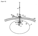
Figure 8 ] is a partial cutaway in cross section showing a state in which the endoscope to which the bending instrument for an endoscope has been attached is positioned above the gastrostomy catheter which has been made indwelling in the body of a patient; - [
Figure 9 ] is a partial cutaway in cross section showing a state in which the endoscope to which the bending instrument for an endoscope has been attached is inserted into the gastrostomy catheter which has been made indwelling in the body of the patient; and - [
Figure 10 ] is a partial cutaway in cross section showing a state in which the indwelling position of the gastrostomy catheter is confirmed by the endoscope. - A mode of embodiment of the present invention will be described below with the aid of the figures.
Figures 1 and 2 show abending instrument 10 for an endoscope according to this mode of embodiment. Thisbending instrument 10 for an endoscope comprises a cylindricalfixed part 11, a stepped cylindricalsliding part 12 which is longer in the axial direction than thefixed part 11, and an extended linkingpart 13 for joining thefixed part 11 and slidingpart 12. Hereinbelow, the side of thefixed part 11 of thebending instrument 10 for an endoscope shall be referred to as the lower side/bottom, and the side of thesliding part 12 shall be referred to as the upper side/top. Thefixed part 11 which is positioned at the lower side of the bendinginstrument 10 for an endoscope comprises a cylindrical body. - The sliding
part 12 comprises a sliding partmain body 12a which is positioned at the bottom, and alatch part 12b which is positioned at the top. The sliding partmain body 12a comprises a cylindrical body the diameter of which is set to be substantially the same as the diameter of the upper end of the fixedpart 11, and the length of which is greater than that of the fixedpart 11. Furthermore, thelatch part 12b comprises a cylindrical body having a larger diameter than the sliding partmain body 12a. Astep 12c is then formed at the lower end of thelatch part 12b. Furthermore, the extended linkingpart 13 joins opposing portions at the top end edge of the fixedpart 11 and the bottom end edge of the sliding partmain body 12a, and it is flexible. Expanded-width parts part 13 are then formed at the two ends of the extended linkingpart 13. - The expanded-
width part 13a is formed by providing concave curves which grow steadily greater in width from the centre of the extended linkingpart 13 towards the fixedpart 11 on both sides of the extended linkingpart 13 in the width direction (the peripheral direction of the fixed part 11) at the boundary between thefixed part 11 and the extended linkingpart 13. Likewise, the expanded-width part 13b is formed by providing concave curves which grow steadily greater in width from the centre of the extended linkingpart 13 towards the sliding partmain body 12a on both sides of the extended linkingpart 13 in the width direction (the peripheral direction of the sliding partmain body 12a) at the boundary between the sliding partmain body 12a and the extended linkingpart 13. - This bending
instrument 10 for an endoscope is produced in the following manner. First of all, an injection moulding apparatus (not depicted) provided with a die formed with a moulding cavity in the shape of the mouldedbody 10a shown inFigure 3 is used to produce themoulded body 10a by injection moulding a moulding material comprising polypropylene or polyethylene or similar under conditions of temperature 200 - 250°C and injection moulding pressure 25 - 40 MPa. Thismoulded body 10a has a linkingpart 13c for joining the fixedpart 11 and slidingpart 12 in a pre-drawn state, and the linkingpart 13c is thicker and shorter than the extended linkingpart 13 of the bendinginstrument 10 for an endoscope. - The lengths of the sections of the moulded
body 10a in the axial direction are set at 3 mm for the fixedpart 11, 4 mm for the linkingpart main body latch part 12b, and the overall length is 30 mm, for example. Furthermore, r (radii) of the concave curves of the expanded-width parts part 11 has an outer diameter of 2.53 mm and an inner diameter of 2.03 mm, and the width of the linkingpart 13c is 0.4 mm. Furthermore, the slidingpart 12 has an inner diameter of 2.08 mm, and the outer diameter of the sliding partmain body 12a is set at around 2.77 mm, while the outer diameter of thelatch part 12b is set at around 3.8 mm. These dimensions are suitably set to fit the dimensions of theendoscope 15 andsheath 14 which will be described later. - Next, the linking
part 13c of this mouldedbody 10a is drawn using a specific drawing apparatus (not depicted). This drawing apparatus is provided with two fixed parts which can advance and retract with respect to each other. For these two fixed parts, it is possible to use a system in which a fixed static plate-like fixed part and a mobile plate-like fixed part which can advance and retract with respect to the static plate-like fixed part are arranged facing each other, and a recess allowing the linkingpart 13c to pass through is formed in the respective upper edges thereof. In this case, the opposing end faces of the fixedpart 11 and the slidingpart 12 are brought into contact with the outside faces of the static plate-like fixed part and the mobile plate-like fixed part, respectively. Thefixed part 11 and the slidingpart 12 are then fixed to the two fixed parts, and the two fixed parts are steadily moved apart to draw the linkingpart 13c to a specific length, 13 mm, for example. - The rate at which the two fixed parts are moved apart in this instance is set to around 1 mm/sec. Furthermore, the deformation of the linking
part 13c when it is drawn is achieved through plastic deformation and elastic deformation. That is to say, the linkingpart 13c slightly contracts from immediately after the end of drawing to become theextended linking part 13, after which the length thereof is maintained. For this reason, the drawing is carried out for a slightly longer time than the 9 seconds required in order to draw a linkingpart 13c of length 4 mm to 13 mm, for example approximately 10 - 13 seconds. Next, the bendinginstrument 10 for an endoscope obtained by drawing is sterilized. This sterilization is carried out by placing the bendinginstrument 10 for an endoscope in ethylene oxide gas at 40 - 50°C for around 20 hours. - The bending
instrument 10 for an endoscope obtained in this manner is attached to theendoscope 15 with thesheath 14 interposed, as shown inFigure 4 . That is to say, thesheath 14 covers the fibrescope shaft 16 (seeFigure 5 ) of theendoscope 15, which will be described later, in order to prevent soiling of thefibrescope shaft 16; the bendinginstrument 10 for an endoscope is used to make the tip end section of thefibrescope shaft 16 bend so that the direction of observation by theendoscope 15 can be changed. Theendoscope 15 has a configuration in which alens 16a is attached to the tip end of thefibrescope shaft 16, and aconnector 17 is attached to the rear end, as shown inFigure 5 . - The
fibrescope shaft 16 is flexible and it consists of a bundle of fibres comprising a light guide for illuminating light, and an image guide for transmitting reflected light via thelens 16a. Theconnector 17 is joined towiring 18a which connects the image guide to an image display device (not depicted), andwiring 18b which connects the light guide to a light source device (not depicted). The tip end of thesheath 14 is closed off by the light-transmissive window part (not depicted), and thebase end 14a thereof at the open side comprises a tube of somewhat larger diameter than the other sections; the sheath is also flexible. - The
sheath 14 is attached to thefibrescope shaft 16 by pushing the tip-end narrow-diameter part 17a of theconnector 17 into thebase end 14a. In this case, thesheath 14 is prevented from being removed from thefibrescope shaft 16 using a member such as a clamp, binding or clasp. In this state, thelens 16a is designed to come into contact with the inner surface of the window part. Thesheath 14 is made of the same material as the material which constitutes the bendinginstrument 10 for an endoscope, and the sheath is inserted from the top opening of the bendinginstrument 10 for an endoscope; the sheath is made integral with the bendinginstrument 10 for an endoscope by welding the tip end at the outer periphery of the sheath to the inner peripheral surface of the fixedpart 11. The welding in this case is preferably heat welding. - Furthermore, an
insertion aid 20 is attached to the top part of the bendinginstrument 10 for an endoscope at the outer periphery of thesheath 14. Theinsertion aid 20 is an instrument which is fitted to the gastrostomy catheter 25 (to be described later) in order to smooth the operation to insert theendoscope 15 etc. into thegastrostomy catheter 25, and also to supply air into the stomach S (seeFigures 8 to 10 ) so as to expand the stomach S, and it comprises a cylindricalmain body 21, avalve restraining member 22, a disc-shaped sealing member with a hole (not depicted), and abranch pipe 23 which branches off from the cylindricalmain body 21. The cylindricalmain body 21 is formed as a cylinder in which is formed a through-hole which allows the passage of thefibrescope shaft 16 together with thesheath 14. Furthermore, aconnector 21a is formed at the lower end of the cylindricalmain body 21, and aninsertion opening 21b is formed at the upper end of the cylindricalmain body 21. - The
connector 21a has a configuration in which a large-diameter section of substantially the same diameter as the central section of the cylindricalmain body 21 is formed in substantially the centre in the axial direction of a narrow-diameter section which is narrower in diameter than the central section of the cylindricalmain body 21. Theinsertion opening 21b is formed with a larger diameter than the central section of the cylindricalmain body 21. Furthermore, the top part of theinsertion opening 21b is narrower in diameter than the bottom part thereof, and an engaging part with which thevalve restraining member 22 engages is formed on the outer peripheral surface thereof, although this is not shown in the figures. Thevalve restraining member 22 comprises a cap-like body formed with a ceiling part and a hole part, and a sealing member is housed therein. - The sealing member comprises a deformable annular elastomer, for example natural rubber, synthetic rubber, silicone or the like, and the inner diameter thereof is somewhat smaller than the inner diameter of the through-hole of the cylindrical
main body 21, and the outer diameter thereof is substantially the same as the outer diameter of the upper end face of theinsertion opening 21b. Furthermore, thebranch pipe 23 is formed as a cylinder which extends obliquely upwards from the upper side of theconnector 21a on the cylindricalmain body 21, at an inclination of approximately 45° with respect to the cylindricalmain body 21, and it is narrower in diameter than the cylindricalmain body 21. An air supply device (not depicted) is connected to the tip end of thisbranch pipe 23, and air which is supplied by the air supply device passes through thebranch pipe 23 and is fed into the cylindricalmain body 21. - As shown in
Figure 6 , thegastrostomy catheter 25 comprises an externalfixed part 26, atubular part 27 which is linked to the centre of the lower end surface of the external fixedpart 26, and a stomach-internalfixed part 28 which is attached to the lower end of thetubular part 27, all these components being made of a soft plastic material such as polyurethane or silicone. The external fixedpart 26 comprises aninsertion opening 26a which is formed as a thick ring, and projectingpieces insertion opening 26a. Avalve body 26e which is formed with a central slit is then provided on the inner peripheral surface of aninsertion hole 26d which is formed in the centre of theinsertion opening 26a, passing through vertically. - Furthermore, a
cover part 29 for closing off theinsertion hole 26d of theinsertion opening 26a is joined to the tip end of the projectingpiece 26b. Thecover part 29 comprises an elongate strip-shaped linkingpart 29a which is linked to the projectingpiece 26b, abroad part 29b which is short and wide, and is formed at the tip end of the strip-shaped linkingpart 29a, and astopper part 29c shaped like a round column which is short in the axial direction and is provided on thebroad part 29b. Thestopper part 29c is provided on thebroad part 29b, so as to face theinsertion hole 26d when the strip-shaped linkingpart 29a is bent to position thebroad part 29b above theinsertion opening 26a. - The
tubular part 27 comprises an elongate cylindrical body inside which is formed a through-hole 27a (seeFigure 7 ) for allowing the passage of fluids such as nutrients and food in fluid form, and the upper end of the through-hole 27a communicates with theinsertion hole 26d of the external fixedpart 26. The stomach-internalfixed part 28 is connected to thetubular part 27 by way of aconnector 27b which is fixed to the lower end of thetubular part 27. This stomach-internalfixed part 28 comprises four strip-shaped linkingparts 28a which extend in four directions from the edge of a lower end opening of theconnector 27b, four linkingfilm parts 28b which are provided between the upper parts of each of the linkingparts 28a and form a stomach wall contact part with the four linkingparts 28a, and a convergingpart 28c where the tip ends of all of the linkingparts 28a converge. - The four linking
parts 28a comprise strip-shaped members which are bent into substantially semi-circular shapes which split into four directions from the lower end of theconnector 27b, respectively extending downwards from the horizontal, after which they converge below the central axis of thetubular part 27, linking to form the convergingpart 28c. Furthermore, each of the linkingparts 28a and each of the linkingfilm parts 28b is made of a flexible soft elastic material, and the overall shape thereof is normally maintained as a flat and substantially spherical shape, as shown inFigure 6(b) , but they can be extended into a straight elongate shape by pulling the convergingpart 28c downwards. Furthermore, the lower end of theinsertion hole 27a in thetubular part 27 opens between the upper ends of the linkingparts 28a. - The space formed between the bottom parts of the linking
parts 28a forms a channel for the passage of fluids such as nutrients and food in fluid form delivered from the through-hole 27a in thetubular part 27, into the stomach S. A further through-hole 28d is formed in the centre of the convergingpart 28c, and a cylindricalengaging part 28e (seeFigure 7 ) which can engage with thestep 12c of the bendinginstrument 10 for an endoscope is formed at the top part of the through-hole 28d (convergingpart 28c). That is to say, the through-hole 28d is constituted by the inner peripheral surface of the cylindricalengaging part 28e, and the diameter thereof is smaller than the diameter of theinsertion hole 26d in the external fixedpart 26 and the diameter of the through-hole 27a in thetubular part 27. - Moreover, the outer diameters of the fixed
part 11 and the sliding partmain body 12a of the bendinginstrument 10 for an endoscope are smaller than the diameter of the through-hole 28d of the stomach-internalfixed part 28. Furthermore, the outer diameter of thestep 12c is smaller than the diameters of the through-hole 26d of the external fixedpart 26 and the through-hole 27a of thetubular part 27, but greater than the diameter of the through-hole 28d of the stomach-internalfixed part 28. Consequently, when theendoscope 15 to which thesheath 14 and bendinginstrument 10 for an endoscope have been attached is inserted into thegastrostomy catheter 25 from theinsertion hole 26d towards the through-hole 28d, the bendinginstrument 10 for an endoscope passes through theinsertion hole 26d of the external fixedpart 26 and the through-hole 27a of thetubular part 27. - The
fixed part 11 and the sliding partmain body 12a can then pass through the inside of thegastrostomy catheter 25 from theinsertion hole 26d towards the through-hole 28d, but when thestep 12c of the slidingpart 12 reaches the cylindricalengaging part 28e, thestep 12c comes into contact with the cylindricalengaging part 28e, and thelatch part 12b cannot pass through the through-hole 28d. If theendoscope 15 and other members are inserted further in this state, the tip end section of theendoscope 15 bends, as shown inFigure 7 , and the orientation of the tip end of theendoscope 15 is changed. In this case, the extended linkingpart 13 is positioned at the inner periphery of thefibrescope shaft 16 and other members when they are bent, and the distance between the upper end edge of the fixed part 11 (the lower end inFigure 7 ) and the lower end edge of the slidingpart 12 remains substantially constant. - Furthermore, the
connector 21a of theinsertion aid 20 is designed to be able to be connected to theinsertion hole 26d of thegastrostomy catheter 25 in an airtight and liquid-tight manner. Furthermore, theconnector 21a pushes the slit of thevalve body 26e formed in theinsertion hole 26d outwards at this point so that the outer peripheral surface of theconnector 21a and the peripheral edge of the slit are in very close contact. In addition, when theinsertion aid 20 is attached to thefibrescope shaft 16 which is covered by thesheath 14, the area between the sealing member and thesheath 14 is in airtight and liquid tight contact. - A description will be given next of the method of confirming the indwelling position of the
gastrostomy catheter 25 and the state of the inside of the stomach S by using theendoscope 15 to which the bendinginstrument 10 for an endoscope,sheath 14 andinsertion aid 20 have been attached, with the aid ofFigures 8 to 10 .Figure 8 shows a state in which thegastrostomy catheter 25 is indwelling in a gastric fistula provided in the patients' abdominal wall AW and stomach wall SW, and in the state shown inFigure 8 , thestopper part 29c of thegastrostomy catheter 25 is removed from theinsertion hole 26d so that the top end of theinsertion hole 26d is open. Furthermore, theendoscope 15 to which the bendinginstrument 10 for an endoscope,sheath 14 andinsertion aid 20 have been attached is positioned above thegastrostomy catheter 25. - The
endoscope 15 and other members which are in this state are moved downwards as shown by the arrow in the figure so that thefibrescope shaft 16 protruding from the lower end of theinsertion aid 20 is inserted into theinsertion hole 26d of thegastrostomy catheter 25 together with thesheath 14 and bendinginstrument 10 for an endoscope. By means of this, theconnector 21a of theinsertion aid 20 engages with theinsertion hole 26d of thegastrostomy catheter 25, as shown inFigure 9 . Theendoscope 15 and other members are then inserted further towards the lower side of thegastrostomy catheter 25, and the lower section of thefibrescope shaft 16,sheath 14 and bendinginstrument 10 for an endoscope are made to project downwards from the through-hole 28d of thegastrostomy catheter 25. - Next, air is supplied from the air supply device to the
branch pipe 23, and this air is fed into the stomach S from theconnector 21a through thetubular part 27 of thegastrostomy catheter 25. By means of this, the stomach S expands, as shown inFigure 10 . In this state, light is produced by the light source device, whereby the light passes through thewiring 18b and the light guide of thefibrescope shaft 16, shining light towards the stomach wall SW. Furthermore, as shown inFigure 10 , the lower section of thefibrescope shaft 16 may, in this case, be bent to change the position of illumination of the stomach wall SW by the light guide, by pushing theendoscope 15 and other members further into the body, if this is required. - That is to say, if the
fibrescope shaft 16 is pushed further in with respect to the bendinginstrument 10 for an endoscope from the state shown inFigure 9 , the fixedpart 11 of the bendinginstrument 10 for an endoscope and the sliding partmain body 12a of the slidingpart 12 pass through the through-hole 28d of the stomach-internalfixed part 28, as shown inFigure 7 , and enter the stomach S, but theengaging part 12b of the slidingpart 12 comes into contact with the cylindricalengaging part 28e and is held inside the stomach-internalfixed part 28. Consequently, the fixedpart 11 moves so as to describe an arc with the extended linkingpart 13 as the radius thereof, and the tip end sections of thefibrescope shaft 16 andsheath 14 protrude inside the stomach S while bending to follow the movement of the fixedpart 11. - The range shown by the two-dot chain line a in
Figure 10 shows the range of illumination of the light from the light guide. The reflected light from the stomach wall SW which is illuminated by the light guide is then focused by thelens 16a, after which it is sent to the image display device via the image guide of thefibrescope shaft 16 and thewiring 18a. The images which have been sent to the image display device are enlarged and displayed on the display part of the image display device, which makes it possible to confirm from these images displayed on the image display part whether or not the stomach-internalfixed part 28 of thegastrostomy catheter 25 is correctly arranged inside the stomach S, and to confirm the state of the stomach S. If it can be confirmed that thegastrostomy catheter 25 is indwelling in the correct state and the state of the stomach S can be confirmed, theendoscope 15 and other members are withdrawn. - This withdrawal operation involves pulling the
endoscope 15 and other members slightly upwards, and once the state inFigure 9 has been reached, the engagement between theinsertion aid 20 andgastrostomy catheter 25 is released. Theendoscope 15 and other members are then pulled upwards to remove them from thegastrostomy catheter 25. Theinsertion aid 20 is then removed from thesheath 14, after which thefibrescope shaft 16 is withdrawn from thesheath 14. The bendinginstrument 10 for an endoscope and thesheath 14 are then discarded, and theendoscope 15 can be used on another occasion. Furthermore, when theendoscope 15 is reused, asheath 14 to which anew bending instrument 10 for an endoscope is attached is employed. - Furthermore, when liquid nutrients, for example, are supplied to the patient's stomach S through the
gastrostomy catheter 25 which has been made indwelling in the patient's body, a connector of a tube extending from a container housing the nutrients is connected to theinsertion hole 26d of thegastrostomy catheter 25, and the nutrients are supplied to the patient through the tube and thegastrostomy catheter 25. Furthermore, the tube of the container housing the nutrients is removed from theinsertion hole 26d of thegastrostomy catheter 25 after use, and theinsertion hole 26d is closed with thestopper part 29c. - In this way, the bending
instrument 10 for an endoscope according to this mode of embodiment is obtained by first of all injection moulding the mouldedbody 10a which comprises the fixedpart 11, slidingpart 12 and linkingpart 13c for joining the fixedpart 11 and slidingpart 12, after which the linkingpart 13c of the mouldedbody 10a is drawn to a specific length by drawing to form the extended linkingpart 13. In this way, the mouldedbody 10a having the short andthick linking part 13c is moulded as a provisional moulding, rather than the bendinginstrument 10 for an endoscope with the elongate extended linkingpart 13 which is difficult to injection mould being injection moulded from the outset, and therefore themoulded body 10a can be easily moulded. Furthermore, the linkingpart 13c can be easily drawn, and the length of the resulting extended linkingpart 13 can be freely set. Cost savings can also be envisaged. - Furthermore, the two end sections of the linking
part 13c of the mouldedbody 10a in the longitudinal direction comprise the expanded-width parts part 13c with the fixedpart 11 and the slidingpart 12 is increased, and the linkingpart 13 can be easily drawn. In addition, when the assembly is used, theendoscope 15 to which the bendinginstrument 10 for an endoscope has been attached is inserted into thegastrostomy catheter 25, and theengaging part 12b of the slidingpart 12 engages with the cylindricalengaging part 28e; if theendoscope 15 is then pushed further into thegastrostomy catheter 25, the progression of the tip end of theendoscope 15 in the direction of insertion is restricted by the fixedpart 11, and it can only move together with the fixedpart 11 in the direction of an arc with the length of the extended linkingpart 13 as the radius. - The section of the
endoscope 15 further towards the base end than the tip end is then pushed outwards at the tip end of thegastrostomy catheter 25, and therefore theendoscope 15 protrudes outwards at the tip end of thegastrostomy catheter 25 while bending. Consequently, theendoscope 15 can rotate about an axis, and the insertion length of theendoscope 15 can be adjusted, so that the tip end of theendoscope 15 can be oriented in any direction. Furthermore, the fixedpart 11 is attached to the outer periphery of the tip end of theendoscope 15, and therefore there is no impediment to observation of the stomach wall SW etc. by the endoscope. - This means that the direction of observation by the
endoscope 15 can be changed using a simple operation, and the state of the stomach wall SW and the indwelling position of thegastrostomy catheter 25 can be more reliably confirmed. Furthermore, the bendinginstrument 10 for an endoscope according to this mode of embodiment is fixed to the tip end of thesheath 14, and then attached to theendoscope 15 together with thesheath 14, and therefore there is virtually no need to sterilize or clean theendoscope 15 after it has been used, and costs involved in cleaning and sterilization are largely unnecessary, and it is possible to extend the lifespan of theendoscope 15. - Furthermore, the bending instrument for an endoscope according to this mode of embodiment is not limited to the mode of embodiment described above, and suitable modifications may be made within the technical scope of the present invention. For example, in the mode of embodiment described above, the bending
instrument 10 for an endoscope is fixed to thesheath 14 by welding, but it may be fixed by bonding or the like rather than by welding, or the bendinginstrument 10 for an endoscope may be detachable from thesheath 14. Furthermore, thesheath 14 may be omitted, and the bendinginstrument 10 for an endoscope may be attached directly to theendoscope 15. - In addition, the extended linking
part 13 may have various shapes such as a cord-like shape, thread-like shape, rod-like shape or a narrow sheet-like shape. Furthermore, the length of the extended linkingpart 13 may be freely set, and if the length of the linkingpart 13c is set at 4 mm, as in the mode of embodiment described above, the length of the extended linkingpart 13 may be 4 - 13 mm. In addition, the shapes of the other components which make up the bendinginstrument 10 for an endoscope may be suitably modified. Furthermore, the drawing of the linkingpart 13c may involve hot drawing at a specific temperature. - 10...bending instrument for an endoscope; 10a...moulded body; 11...fixed part; 12...sliding part; 12b...latch part; 12c...step; 13...extended linking part; 13a, 13b...expanded-width parts; 13c...linking part; 14...sheath; 15...endoscope; 25...gastrostomy catheter; 27...tubular part; 27a...through-hole; 28...stomach-internal fixed part; 28d...through-hole; 28e...cylindrical engaging part; AW...abdominal wall; S...stomach; SW...stomach wall.
Claims (7)
- Bending instrument for an endoscope which is used for attachment to the endoscope in order to bend the tip end section of the endoscope,
said bending instrument for an endoscope being characterized in that a fixed part which is attached to the outer periphery of the tip end of the endoscope, a sliding part which is slidably attached further towards the base end of the endoscope than the portion where the fixed part is attached, and a linking part for joining specific opposing portions of the fixed part and the sliding part are moulded as a single piece,
after which a flexible extended linking part is formed by extending the linking part to a specific length by drawing, and the gap between the fixed part and the sliding part can be restricted by the extended linking part so that it does not exceed the specific length. - Bending instrument for an endoscope according to Claim 1, in which the fixed part and the sliding part are formed to be annular or cylindrical, and specific portions on opposing end faces of the fixed part and
the sliding part are joined by the extended linking part. - Bending instrument for an endoscope according to Claim 1 or 2, in which both end portions of the extended linking part in the longitudinal direction are thicker or wider than the central portion thereof.
- Bending instrument for an endoscope according to any one of Claims 1 to 3, which is used for the insertion of the endoscope into a gastrostomy catheter which is provided with a tubular part formed with an internal through-hole, and a stomach-internal fixed part which is linked to the tip end of the tubular part with the tip end of the through-hole of the tubular part remaining open and which is provided with an engaging part in the region of the tip end of the through-hole;
the tubular part is positioned in a gastric fistula formed between the surface of a patient's skin and the inner surface of the stomach wall, and the gastrostomy catheter is made indwelling in the gastric fistula with the stomach-internal fixed part positioned inside the stomach; and
the fixed part can pass through the inside of the gastrostomy catheter together with the endoscope, and
the sliding part can pass through the through-hole of the gastrostomy catheter but engages with the engaging part of the stomach-internal fixed part in such a way that it cannot pass through the stomach-internal fixed part. - Bending instrument for an endoscope according to any one of Claims 1 to 4, in which the endoscope is covered by a sheath, and the bending instrument for an endoscope is attached to the endoscope with the sheath interposed.
- Method of producing a bending instrument for an endoscope which is used for attachment to an endoscope in order to bend the tip end section of the endoscope, said method of producing a bending instrument for an endoscope being characterized in that it includes:a moulding step in which a fixed part which is attached to the outer periphery of the tip end of the endoscope,a sliding part which is slidably attached further towards the base end of the endoscope than the portion where the fixed part is attached, and a linking part for joining specific opposing portions of the fixed part and the sliding part are moulded as a single piece by injection moulding; anda drawing step in which the linking part of the moulded body moulded in the moulding step is formed into a flexible extended linking part for restricting the gap between the fixed part and the sliding part so that it does not exceed the specific length, by extending the linking part to a specific length by drawing.
- Method of producing a bending instrument for an endoscope according to Claim 6, in which the endoscope is covered by a sheath when it is used, and the moulded body moulded in the moulding step is moulded from the same material as the material constituting the sheath, and a welding step is carried out after the drawing step, in order to weld the fixed part of the bending instrument for an endoscope to the outer periphery of the tip end of the sheath.
Applications Claiming Priority (1)
| Application Number | Priority Date | Filing Date | Title |
|---|---|---|---|
| JP2009127211A JP5340811B2 (en) | 2009-05-27 | 2009-05-27 | Method of manufacturing a bending tool for an endoscope |
Publications (2)
| Publication Number | Publication Date |
|---|---|
| EP2255720A1 true EP2255720A1 (en) | 2010-12-01 |
| EP2255720B1 EP2255720B1 (en) | 2013-12-18 |
Family
ID=42334495
Family Applications (1)
| Application Number | Title | Priority Date | Filing Date |
|---|---|---|---|
| EP10004638.2A Active EP2255720B1 (en) | 2009-05-27 | 2010-05-03 | Bending instrument for an endoscope and method of producing same |
Country Status (2)
| Country | Link |
|---|---|
| EP (1) | EP2255720B1 (en) |
| JP (1) | JP5340811B2 (en) |
Citations (5)
| Publication number | Priority date | Publication date | Assignee | Title |
|---|---|---|---|---|
| GB1198617A (en) * | 1966-10-21 | 1970-07-15 | Itw Ltd | Elongated Plastics Members. |
| US5306245A (en) * | 1993-02-23 | 1994-04-26 | Advanced Surgical Inc. | Articulating device |
| WO1998026724A1 (en) * | 1996-12-19 | 1998-06-25 | Ep Technologies, Inc. | Branched structures for supporting multiple electrode elements |
| JP2001120496A (en) | 1999-10-28 | 2001-05-08 | Olympus Optical Co Ltd | Wound sheath for probe |
| EP2074931A1 (en) * | 2007-12-27 | 2009-07-01 | Covidien AG | Bending instrument for an endoscope and endoscope set |
Family Cites Families (4)
| Publication number | Priority date | Publication date | Assignee | Title |
|---|---|---|---|---|
| JP3543027B2 (en) * | 1995-04-10 | 2004-07-14 | オリンパス株式会社 | Curved sheath for probe |
| JP2003204920A (en) * | 2002-01-11 | 2003-07-22 | Olympus Optical Co Ltd | Insertion assisting tool |
| JP5226197B2 (en) * | 2006-08-25 | 2013-07-03 | オリンパス株式会社 | Endoscope guide tube and endoscope apparatus |
| JP2007296382A (en) * | 2007-07-30 | 2007-11-15 | Olympus Corp | Insertion assisting tool |
-
2009
- 2009-05-27 JP JP2009127211A patent/JP5340811B2/en not_active Expired - Fee Related
-
2010
- 2010-05-03 EP EP10004638.2A patent/EP2255720B1/en active Active
Patent Citations (5)
| Publication number | Priority date | Publication date | Assignee | Title |
|---|---|---|---|---|
| GB1198617A (en) * | 1966-10-21 | 1970-07-15 | Itw Ltd | Elongated Plastics Members. |
| US5306245A (en) * | 1993-02-23 | 1994-04-26 | Advanced Surgical Inc. | Articulating device |
| WO1998026724A1 (en) * | 1996-12-19 | 1998-06-25 | Ep Technologies, Inc. | Branched structures for supporting multiple electrode elements |
| JP2001120496A (en) | 1999-10-28 | 2001-05-08 | Olympus Optical Co Ltd | Wound sheath for probe |
| EP2074931A1 (en) * | 2007-12-27 | 2009-07-01 | Covidien AG | Bending instrument for an endoscope and endoscope set |
Also Published As
| Publication number | Publication date |
|---|---|
| JP5340811B2 (en) | 2013-11-13 |
| JP2010273749A (en) | 2010-12-09 |
| EP2255720B1 (en) | 2013-12-18 |
Similar Documents
| Publication | Publication Date | Title |
|---|---|---|
| US7771396B2 (en) | Intubation device for enteral feeding | |
| US8679002B2 (en) | Endoscope system for gastrostomy catheter placement | |
| JP5383980B2 (en) | Intubation system for use with an endoscope | |
| US20090062606A1 (en) | Endoscope guiding tube device | |
| JP5682206B2 (en) | Introduction aid and fistula catheter kit | |
| US20070239171A1 (en) | Medical snaring device | |
| JP4119904B2 (en) | Medical catheter fixture | |
| JP2009153764A (en) | Insertion assisting tool for endoscope | |
| JP2007296363A (en) | Quick mounting implement for catheter | |
| US20070239137A1 (en) | Intubation device for colonic decompression | |
| US8246535B2 (en) | Bending instrument for an endoscope and endoscope set | |
| EP2255720B1 (en) | Bending instrument for an endoscope and method of producing same | |
| US20060084838A1 (en) | Instrument for re-insertion of a gastrostoma tube | |
| EP2095839A1 (en) | Device and medical instrument for preventing excessive insertion of a rod-like member | |
| EP2233063B1 (en) | Bending instrument for an endoscope and endoscope set | |
| CN213282824U (en) | Endoscopic examination apparatus | |
| JP2009061187A (en) | Catheter replacement auxiliary implement and catheter replacement kit | |
| CN112638231A (en) | Outer sleeve | |
| KR101429360B1 (en) | Paracentesis needle guide |
Legal Events
| Date | Code | Title | Description |
|---|---|---|---|
| PUAI | Public reference made under article 153(3) epc to a published international application that has entered the european phase |
Free format text: ORIGINAL CODE: 0009012 |
|
| AK | Designated contracting states |
Kind code of ref document: A1 Designated state(s): AL AT BE BG CH CY CZ DE DK EE ES FI FR GB GR HR HU IE IS IT LI LT LU LV MC MK MT NL NO PL PT RO SE SI SK SM TR |
|
| AX | Request for extension of the european patent |
Extension state: BA ME RS |
|
| 17P | Request for examination filed |
Effective date: 20110302 |
|
| 17Q | First examination report despatched |
Effective date: 20120530 |
|
| RAP1 | Party data changed (applicant data changed or rights of an application transferred) |
Owner name: COVIDIEN LP |
|
| GRAP | Despatch of communication of intention to grant a patent |
Free format text: ORIGINAL CODE: EPIDOSNIGR1 |
|
| INTG | Intention to grant announced |
Effective date: 20130730 |
|
| RIN1 | Information on inventor provided before grant (corrected) |
Inventor name: ABE, KAZUHIRO |
|
| GRAS | Grant fee paid |
Free format text: ORIGINAL CODE: EPIDOSNIGR3 |
|
| GRAA | (expected) grant |
Free format text: ORIGINAL CODE: 0009210 |
|
| AK | Designated contracting states |
Kind code of ref document: B1 Designated state(s): AL AT BE BG CH CY CZ DE DK EE ES FI FR GB GR HR HU IE IS IT LI LT LU LV MC MK MT NL NO PL PT RO SE SI SK SM TR |
|
| REG | Reference to a national code |
Ref country code: GB Ref legal event code: FG4D |
|
| REG | Reference to a national code |
Ref country code: CH Ref legal event code: EP |
|
| REG | Reference to a national code |
Ref country code: AT Ref legal event code: REF Ref document number: 645193 Country of ref document: AT Kind code of ref document: T Effective date: 20140115 |
|
| REG | Reference to a national code |
Ref country code: IE Ref legal event code: FG4D |
|
| REG | Reference to a national code |
Ref country code: DE Ref legal event code: R096 Ref document number: 602010012462 Country of ref document: DE Effective date: 20140213 |
|
| REG | Reference to a national code |
Ref country code: NL Ref legal event code: VDEP Effective date: 20131218 |
|
| PG25 | Lapsed in a contracting state [announced via postgrant information from national office to epo] |
Ref country code: HR Free format text: LAPSE BECAUSE OF FAILURE TO SUBMIT A TRANSLATION OF THE DESCRIPTION OR TO PAY THE FEE WITHIN THE PRESCRIBED TIME-LIMIT Effective date: 20131218 Ref country code: LT Free format text: LAPSE BECAUSE OF FAILURE TO SUBMIT A TRANSLATION OF THE DESCRIPTION OR TO PAY THE FEE WITHIN THE PRESCRIBED TIME-LIMIT Effective date: 20131218 Ref country code: SE Free format text: LAPSE BECAUSE OF FAILURE TO SUBMIT A TRANSLATION OF THE DESCRIPTION OR TO PAY THE FEE WITHIN THE PRESCRIBED TIME-LIMIT Effective date: 20131218 Ref country code: NO Free format text: LAPSE BECAUSE OF FAILURE TO SUBMIT A TRANSLATION OF THE DESCRIPTION OR TO PAY THE FEE WITHIN THE PRESCRIBED TIME-LIMIT Effective date: 20140318 Ref country code: FI Free format text: LAPSE BECAUSE OF FAILURE TO SUBMIT A TRANSLATION OF THE DESCRIPTION OR TO PAY THE FEE WITHIN THE PRESCRIBED TIME-LIMIT Effective date: 20131218 |
|
| REG | Reference to a national code |
Ref country code: AT Ref legal event code: MK05 Ref document number: 645193 Country of ref document: AT Kind code of ref document: T Effective date: 20131218 |
|
| REG | Reference to a national code |
Ref country code: LT Ref legal event code: MG4D |
|
| PG25 | Lapsed in a contracting state [announced via postgrant information from national office to epo] |
Ref country code: LV Free format text: LAPSE BECAUSE OF FAILURE TO SUBMIT A TRANSLATION OF THE DESCRIPTION OR TO PAY THE FEE WITHIN THE PRESCRIBED TIME-LIMIT Effective date: 20131218 |
|
| PG25 | Lapsed in a contracting state [announced via postgrant information from national office to epo] |
Ref country code: IS Free format text: LAPSE BECAUSE OF FAILURE TO SUBMIT A TRANSLATION OF THE DESCRIPTION OR TO PAY THE FEE WITHIN THE PRESCRIBED TIME-LIMIT Effective date: 20140418 Ref country code: EE Free format text: LAPSE BECAUSE OF FAILURE TO SUBMIT A TRANSLATION OF THE DESCRIPTION OR TO PAY THE FEE WITHIN THE PRESCRIBED TIME-LIMIT Effective date: 20131218 Ref country code: BE Free format text: LAPSE BECAUSE OF FAILURE TO SUBMIT A TRANSLATION OF THE DESCRIPTION OR TO PAY THE FEE WITHIN THE PRESCRIBED TIME-LIMIT Effective date: 20131218 |
|
| PG25 | Lapsed in a contracting state [announced via postgrant information from national office to epo] |
Ref country code: PT Free format text: LAPSE BECAUSE OF FAILURE TO SUBMIT A TRANSLATION OF THE DESCRIPTION OR TO PAY THE FEE WITHIN THE PRESCRIBED TIME-LIMIT Effective date: 20140418 Ref country code: CY Free format text: LAPSE BECAUSE OF FAILURE TO SUBMIT A TRANSLATION OF THE DESCRIPTION OR TO PAY THE FEE WITHIN THE PRESCRIBED TIME-LIMIT Effective date: 20131218 Ref country code: AT Free format text: LAPSE BECAUSE OF FAILURE TO SUBMIT A TRANSLATION OF THE DESCRIPTION OR TO PAY THE FEE WITHIN THE PRESCRIBED TIME-LIMIT Effective date: 20131218 Ref country code: SK Free format text: LAPSE BECAUSE OF FAILURE TO SUBMIT A TRANSLATION OF THE DESCRIPTION OR TO PAY THE FEE WITHIN THE PRESCRIBED TIME-LIMIT Effective date: 20131218 Ref country code: CZ Free format text: LAPSE BECAUSE OF FAILURE TO SUBMIT A TRANSLATION OF THE DESCRIPTION OR TO PAY THE FEE WITHIN THE PRESCRIBED TIME-LIMIT Effective date: 20131218 Ref country code: ES Free format text: LAPSE BECAUSE OF FAILURE TO SUBMIT A TRANSLATION OF THE DESCRIPTION OR TO PAY THE FEE WITHIN THE PRESCRIBED TIME-LIMIT Effective date: 20131218 Ref country code: NL Free format text: LAPSE BECAUSE OF FAILURE TO SUBMIT A TRANSLATION OF THE DESCRIPTION OR TO PAY THE FEE WITHIN THE PRESCRIBED TIME-LIMIT Effective date: 20131218 Ref country code: RO Free format text: LAPSE BECAUSE OF FAILURE TO SUBMIT A TRANSLATION OF THE DESCRIPTION OR TO PAY THE FEE WITHIN THE PRESCRIBED TIME-LIMIT Effective date: 20131218 Ref country code: PL Free format text: LAPSE BECAUSE OF FAILURE TO SUBMIT A TRANSLATION OF THE DESCRIPTION OR TO PAY THE FEE WITHIN THE PRESCRIBED TIME-LIMIT Effective date: 20131218 |
|
| REG | Reference to a national code |
Ref country code: DE Ref legal event code: R097 Ref document number: 602010012462 Country of ref document: DE |
|
| PLBE | No opposition filed within time limit |
Free format text: ORIGINAL CODE: 0009261 |
|
| STAA | Information on the status of an ep patent application or granted ep patent |
Free format text: STATUS: NO OPPOSITION FILED WITHIN TIME LIMIT |
|
| PG25 | Lapsed in a contracting state [announced via postgrant information from national office to epo] |
Ref country code: DK Free format text: LAPSE BECAUSE OF FAILURE TO SUBMIT A TRANSLATION OF THE DESCRIPTION OR TO PAY THE FEE WITHIN THE PRESCRIBED TIME-LIMIT Effective date: 20131218 |
|
| 26N | No opposition filed |
Effective date: 20140919 |
|
| PG25 | Lapsed in a contracting state [announced via postgrant information from national office to epo] |
Ref country code: LU Free format text: LAPSE BECAUSE OF FAILURE TO SUBMIT A TRANSLATION OF THE DESCRIPTION OR TO PAY THE FEE WITHIN THE PRESCRIBED TIME-LIMIT Effective date: 20140503 |
|
| REG | Reference to a national code |
Ref country code: CH Ref legal event code: PL Ref country code: DE Ref legal event code: R097 Ref document number: 602010012462 Country of ref document: DE Effective date: 20140919 |
|
| PG25 | Lapsed in a contracting state [announced via postgrant information from national office to epo] |
Ref country code: CH Free format text: LAPSE BECAUSE OF NON-PAYMENT OF DUE FEES Effective date: 20140531 Ref country code: LI Free format text: LAPSE BECAUSE OF NON-PAYMENT OF DUE FEES Effective date: 20140531 Ref country code: MC Free format text: LAPSE BECAUSE OF FAILURE TO SUBMIT A TRANSLATION OF THE DESCRIPTION OR TO PAY THE FEE WITHIN THE PRESCRIBED TIME-LIMIT Effective date: 20131218 |
|
| REG | Reference to a national code |
Ref country code: IE Ref legal event code: MM4A |
|
| PG25 | Lapsed in a contracting state [announced via postgrant information from national office to epo] |
Ref country code: IE Free format text: LAPSE BECAUSE OF NON-PAYMENT OF DUE FEES Effective date: 20140503 |
|
| PG25 | Lapsed in a contracting state [announced via postgrant information from national office to epo] |
Ref country code: SI Free format text: LAPSE BECAUSE OF FAILURE TO SUBMIT A TRANSLATION OF THE DESCRIPTION OR TO PAY THE FEE WITHIN THE PRESCRIBED TIME-LIMIT Effective date: 20131218 |
|
| PG25 | Lapsed in a contracting state [announced via postgrant information from national office to epo] |
Ref country code: MT Free format text: LAPSE BECAUSE OF FAILURE TO SUBMIT A TRANSLATION OF THE DESCRIPTION OR TO PAY THE FEE WITHIN THE PRESCRIBED TIME-LIMIT Effective date: 20131218 |
|
| REG | Reference to a national code |
Ref country code: FR Ref legal event code: PLFP Year of fee payment: 7 |
|
| PG25 | Lapsed in a contracting state [announced via postgrant information from national office to epo] |
Ref country code: SM Free format text: LAPSE BECAUSE OF FAILURE TO SUBMIT A TRANSLATION OF THE DESCRIPTION OR TO PAY THE FEE WITHIN THE PRESCRIBED TIME-LIMIT Effective date: 20131218 |
|
| PG25 | Lapsed in a contracting state [announced via postgrant information from national office to epo] |
Ref country code: GR Free format text: LAPSE BECAUSE OF FAILURE TO SUBMIT A TRANSLATION OF THE DESCRIPTION OR TO PAY THE FEE WITHIN THE PRESCRIBED TIME-LIMIT Effective date: 20140319 Ref country code: BG Free format text: LAPSE BECAUSE OF FAILURE TO SUBMIT A TRANSLATION OF THE DESCRIPTION OR TO PAY THE FEE WITHIN THE PRESCRIBED TIME-LIMIT Effective date: 20131218 Ref country code: IT Free format text: LAPSE BECAUSE OF FAILURE TO SUBMIT A TRANSLATION OF THE DESCRIPTION OR TO PAY THE FEE WITHIN THE PRESCRIBED TIME-LIMIT Effective date: 20131218 |
|
| PG25 | Lapsed in a contracting state [announced via postgrant information from national office to epo] |
Ref country code: TR Free format text: LAPSE BECAUSE OF FAILURE TO SUBMIT A TRANSLATION OF THE DESCRIPTION OR TO PAY THE FEE WITHIN THE PRESCRIBED TIME-LIMIT Effective date: 20131218 Ref country code: HU Free format text: LAPSE BECAUSE OF FAILURE TO SUBMIT A TRANSLATION OF THE DESCRIPTION OR TO PAY THE FEE WITHIN THE PRESCRIBED TIME-LIMIT; INVALID AB INITIO Effective date: 20100503 |
|
| REG | Reference to a national code |
Ref country code: FR Ref legal event code: PLFP Year of fee payment: 8 |
|
| REG | Reference to a national code |
Ref country code: GB Ref legal event code: 732E Free format text: REGISTERED BETWEEN 20180208 AND 20180214 |
|
| REG | Reference to a national code |
Ref country code: FR Ref legal event code: PLFP Year of fee payment: 9 |
|
| PG25 | Lapsed in a contracting state [announced via postgrant information from national office to epo] |
Ref country code: MK Free format text: LAPSE BECAUSE OF FAILURE TO SUBMIT A TRANSLATION OF THE DESCRIPTION OR TO PAY THE FEE WITHIN THE PRESCRIBED TIME-LIMIT Effective date: 20131218 |
|
| PG25 | Lapsed in a contracting state [announced via postgrant information from national office to epo] |
Ref country code: AL Free format text: LAPSE BECAUSE OF FAILURE TO SUBMIT A TRANSLATION OF THE DESCRIPTION OR TO PAY THE FEE WITHIN THE PRESCRIBED TIME-LIMIT Effective date: 20131218 |
|
| PGFP | Annual fee paid to national office [announced via postgrant information from national office to epo] |
Ref country code: FR Payment date: 20230526 Year of fee payment: 14 Ref country code: DE Payment date: 20230530 Year of fee payment: 14 |
|
| PGFP | Annual fee paid to national office [announced via postgrant information from national office to epo] |
Ref country code: GB Payment date: 20230529 Year of fee payment: 14 |